

Fujifilm Sonosite X-porte User Manual
USER GUIDE

Manufacturer
FUJIFILM SonoSite, Inc.
21919 30th Drive SE
Bothell, WA 98021 USA
T: 1-888-482-9449 or 1-425-951-1200
EC Authorized Representative
Emergo Europe
Molenstraat 15
2513 BH, The Hague
The Netherlands
Australia Sponsor
FUJIFILM SonoSite Australasia Pty Ltd
114 Old Pittwater Road
BROOKVALE, NSW, 2100
Australia
F: 1-425-951-1201
Caution Federal (United States) law restricts this device to sale by or on the order of a
physician.
SonoMB, SonoSite, Steep Needle Profiling, X-Porte, and the SonoSite logo are registered and unregistered trademarks of FUJIFILM
SonoSite, Inc. in various jurisdictions. Value from Innovation is a trademark of FUJIFILM Holdings America Corporation.
DICOM is a registered trademark of the National Electrical Manufacturers Association.
All other trademarks are the property of their respective owners.
Patents: US 9,451,933; US 9,420,998; US 9,162,255; US 9,151,832; US 8,956,296; US 8,876,719; US 8,861,822; US 8,858,436; US
8,834,372; US 8,805,047; US 8,500,647; US 8,439,840; US 8,355,554; US 8,216,146; US 8,213,467; US 8,147,408; US 8,137,278;
US 8,088,071; US 8,066,642; US 7,804,970; US 7,740,586; US 7,604,596; US 7,591,786; US 7,588,541; US 7,534,211; US
7,449,640; US 7,169,108; US 6,962,566; US 6,648,826; US 6,471,651; US 6,416,475; US 6,383,139; US 6,364,839; US 6,203,498;
US 6,135,961; US 5,893,363; US 5,817,024; US 5,782,769; US 5,722,412; US D712540; US D712539; US D712038; US D712037;
AU: 730822; AU: 727381; CA: 2,372,152; CA: 2,371,711; CN: 98108973.9;CN: 98106133.8; CN: 97113678.5; CN: 103237499; CN:
102753104; CN: 101231457; DE: 69831698.3; DE: 69830539.6; DE: 69730563.5; DE: 60034670.6; DE: 60029777.2; DE:
602004027882.3; DE: 602004023816.3; EP: 1552792; EP: 1589878; EP: 1180971; EP 1180970; EP 0881492; EP: 0875203; EP:
0815793;ES: 2229318; ES: 159878; ES: 1552792; ES: 0881492; FR: 158978; FR: 1552792; FR: 1180970; FR: 0881492; FR: 0875203;
FR: 0815793; GB: 158978; GB: 1552792; GB: 1180971; GB: 1180970; GB: 0881492; GB: 0875203; GB: 0815793; IT: 0881492; IT:
0815793; IT: 1552792; IT: 1589878; JP: 5973349; JP: 5972258; JP: 5782428; JP: 4696150; JP: 1512755; JP: 1512754; JP: 1512753;
JP: 1512752; KR: 532359; KR: 528102; NO: 326814 and NO: 326202.
Part Number: P14645-04
Publication Date: January 2017
Copyright © 2017 FUJIFILM SonoSite, Inc. All Rights reserved.

1. Introduction
About the SonoSite X-Porte User Guide .................................................................................................. 1-1
Changes in version 1.2 ............................................................................................................................. 1-1
Document conventions ............................................................................................................................. 1-1
Getting help .................................................................................................................................................... 1-2
2. Getting started
About the system .................................................................................................................................................. 2-1
Accessories and peripherals .................................................................................................................. 2-3
Preparing the system .......................................................................................................................................... 2-3
Turning on the system .............................................................................................................................. 2-3
Adjusting the height and angle ............................................................................................................ 2-4
USB devices .................................................................................................................................................... 2-5
General interaction ................................................................................................................................................ 2-6
Clinical monitor .............................................................................................................................................. 2-6
VGA or digital video output .................................................................................................................... 2-8
Touch panel ..................................................................................................................................................... 2-8
Onscreen keyboard ...................................................................................................................................2-10
Preparing transducers .......................................................................................................................................2-11
Connecting transducers ..........................................................................................................................2-11
Selecting a transducer and exam type ..........................................................................................2-14
Gel ......................................................................................................................................................................2-19
Sheaths ...........................................................................................................................................................2-20
Ports ............................................................................................................................................................................2-20
Battery charge indicator ...................................................................................................................................2-22
Transporting the system ..................................................................................................................................2-22
Visual Guide videos ............................................................................................................................................2-23
Intended uses .......................................................................................................................................................2-24
3. Setting up the system
Administration settings ....................................................................................................................................... 3-1
CONTENTS
About security settings ............................................................................................................................. 3-2
Managing the Administrator account ................................................................................................ 3-2
Protecting patient information .............................................................................................................. 3-3
Adding and managing user accounts ................................................................................................ 3-3
Logging in ........................................................................................................................................................ 3-5
iii

Audio settings ..........................................................................................................................................................3-6
Calculations settings ............................................................................................................................................. 3-6
Cardiac calculations settings ................................................................................................................... 3-7
Obstetrics calculations settings .............................................................................................................3-7
CDA Report settings ..........................................................................................................................................3-10
Connectivity settings .........................................................................................................................................3-11
Importing and exporting connectivity settings .......................................................................... 3-12
DICOM ...................................................................................................................................................................... 3-13
Configuring the system for DICOM transfer ............................................................................... 3-14
Connecting to the network .................................................................................................................. 3-14
DICOM configuration pages ................................................................................................................ 3-16
Associating devices with locations .................................................................................................. 3-23
Date and Time settings .................................................................................................................................... 3-25
Display Information settings ..........................................................................................................................3-26
Logs ............................................................................................................................................................................3-26
Network Status settings ..................................................................................................................................3-27
Power and Battery settings ........................................................................................................................... 3-28
Presets settings ....................................................................................................................................................3-28
General preferences ................................................................................................................................3-29
Brightness ..................................................................................................................................................... 3-29
Labels .............................................................................................................................................................. 3-30
Exam types .................................................................................................................................................. 3-30
User profile settings ................................................................................................................................. 3-32
Importing and exporting ........................................................................................................................ 3-33
Routing selections .............................................................................................................................................. 3-34
Associating routing selections with exams .................................................................................3-34
Specifying educational DICOM archivers .....................................................................................3-35
System Information settings ......................................................................................................................... 3-36
USB settings ..........................................................................................................................................................3-36
Limitations of JPEG format ................................................................................................................... 3-37
eFilm Lite image-viewer ....................................................................................................................... 3-38
4. Imaging
Imaging modes .......................................................................................................................................................4-1
2D .........................................................................................................................................................................4-2
M Mode ............................................................................................................................................................. 4-2
Color ....................................................................................................................................................................4-3
Doppler .............................................................................................................................................................. 4-4
Dual .....................................................................................................................................................................4-5
Imaging controls .....................................................................................................................................................4-6
Controls in 2D ................................................................................................................................................ 4-8
Controls in Color ........................................................................................................................................4-12
Controls in M Mode .................................................................................................................................4-14
Controls in Doppler .................................................................................................................................. 4-16
Adjusting depth and gain ...............................................................................................................................4-20
Depth ............................................................................................................................................................... 4-20
iv

Gain .................................................................................................................................................................. 4-21
Freezing, viewing frames, and zooming .................................................................................................4-22
Freezing the image .................................................................................................................................. 4-22
Viewing the cine buffer .......................................................................................................................... 4-22
Zooming in on the image ..................................................................................................................... 4-23
Visualizing needles ............................................................................................................................................. 4-24
Needle size and angle ............................................................................................................................4-27
Additional recommendations .............................................................................................................. 4-27
Labeling images ...................................................................................................................................................4-28
Adding text labels ..................................................................................................................................... 4-28
Adding arrows ............................................................................................................................................4-29
Adding pictographs .................................................................................................................................. 4-29
Setting the home position .................................................................................................................... 4-30
Labeling during review ........................................................................................................................... 4-30
Entering patient information ......................................................................................................................... 4-31
Editing patient information ................................................................................................................... 4-31
Entering patient information manually ........................................................................................... 4-32
Entering patient information from the worklist .........................................................................4-32
Ending the exam .......................................................................................................................................4-35
Patient form fields .....................................................................................................................................4-35
Images and clips ..................................................................................................................................................4-38
Reviewing .....................................................................................................................................................4-38
Printing images ........................................................................................................................................... 4-41
Archiving and exporting ........................................................................................................................ 4-41
Saving images and video clips ........................................................................................................... 4-44
DVR recording .......................................................................................................................................................4-47
Image Gallery ........................................................................................................................................................ 4-48
ECG ............................................................................................................................................................................ 4-49
5. Measurements and calculations
Measuring .................................................................................................................................................................. 5-1
Calipers .............................................................................................................................................................. 5-1
Viewing and deleting measurement results ..................................................................................5-2
Basic measurements in 2D ..................................................................................................................... 5-2
Basic measurements in M Mode ......................................................................................................... 5-3
Basic measurements in Doppler ..........................................................................................................5-4
Assigning measurements to calculations ........................................................................................ 5-8
About calculations ................................................................................................................................................5-8
Overview ..........................................................................................................................................................5-9
Percent reduction calculations ............................................................................................................5-11
Volume calculation .................................................................................................................................... 5-12
Volume flow calculation ......................................................................................................................... 5-12
Exam-based calculations ................................................................................................................................5-13
Abdominal calculations .......................................................................................................................... 5-13
Arterial calculations ..................................................................................................................................5-14
Cardiac calculations .................................................................................................................................. 5-18
v

Gynecological calculations ................................................................................................................... 5-35
Obstetrics calculations ..........................................................................................................................5-38
Small Parts and MSK calculations ..................................................................................................... 5-44
Acute Care calculations .......................................................................................................................... 5-45
Transcranial Doppler and Orbital calculations ............................................................................ 5-49
Worksheets and reports .................................................................................................................................. 5-52
Report preview ...........................................................................................................................................5-53
Acute Care and MSK worksheets ....................................................................................................5-54
Printing reports and worksheets ....................................................................................................... 5-56
Displaying reports after the exam has ended ............................................................................ 5-56
Customizing worksheets ....................................................................................................................... 5-56
Measuring during review ...................................................................................................................... 5-57
6. Measurement references
Measurement accuracy ......................................................................................................................................6-1
Sources of measurement errors ...........................................................................................................6-3
Measurement publications and terminology ...........................................................................................6-4
Cardiac references .......................................................................................................................................6-4
Obstetrical references ............................................................................................................................. 6-14
General references ................................................................................................................................... 6-20
7. Troubleshooting and maintenance
Troubleshooting ...................................................................................................................................................... 7-1
Software licensing ................................................................................................................................................. 7-2
Maintenance ............................................................................................................................................................. 7-5
System backups ............................................................................................................................................7-5
Servicing ........................................................................................................................................................... 7-6
8. Cleaning and disinfecting
Before getting started .........................................................................................................................................8-1
Determining the required cleaning and disinfecting level ................................................................8-2
Spaulding classifications ...........................................................................................................................8-2
Clean and disinfect system and transducer to a high level (semi-critical uses) ......... 8-3
Clean and disinfect system and transducer to a low level (non-critical uses) ............ 8-8
Storing the transducer ..................................................................................................................................... 8-11
Transporting the transducer .......................................................................................................................... 8-11
Accessories ............................................................................................................................................................ 8-13
Cleaning and disinfecting accessories ............................................................................................ 8-13
Cleaning and disinfecting the stand or Triple Transducer Connect (TTC) .................. 8-14
Cleaning the footswitch ....................................................................................................................... 8-14
Cleaning and disinfecting the ECG cable and slave cable ...................................................8-15
vi

9. Safety
Ergonomic safety ................................................................................................................................................... 9-1
Position the system ....................................................................................................................................9-2
Position yourself ...........................................................................................................................................9-2
Take breaks, exercise, and vary activities .......................................................................................9-3
Electrical safety ....................................................................................................................................................... 9-3
Electrical safety classification .................................................................................................................9-5
Isolating the SonoSite SonoSite X-Porte ultrasound system from power .................... 9-6
Equipment safety ................................................................................................................................................... 9-6
Clinical Safety ...........................................................................................................................................................9-8
Electromagnetic compatibility ......................................................................................................................... 9-9
Wireless transmission ............................................................................................................................. 9-10
Electrostatic discharge ............................................................................................................................ 9-11
Separation distance .................................................................................................................................. 9-12
Compatible accessories and peripherals ....................................................................................... 9-12
Manufacturer’s declaration ................................................................................................................... 9-15
Labeling Symbols ................................................................................................................................................ 9-19
Specifications ........................................................................................................................................................ 9-23
Dimensions ...................................................................................................................................................9-23
Environmental limits ................................................................................................................................9-24
Electrical ......................................................................................................................................................... 9-25
Imaging modes ........................................................................................................................................... 9-25
Image and video clip storage capacity ..........................................................................................9-25
Standards ................................................................................................................................................................ 9-25
Electromechanical safety standards ................................................................................................9-25
EMC standards classification ............................................................................................................... 9-26
DICOM standard ........................................................................................................................................9-26
HIPAA standard .......................................................................................................................................... 9-26
10. Acoustic output
ALARA principle .................................................................................................................................................. 10-1
Applying the ALARA principle ........................................................................................................... 10-1
Direct, indirect, and receiver controls ............................................................................................. 10-2
Acoustic artifacts ................................................................................................................................................. 10-3
Guidelines for reducing MI and TI .............................................................................................................. 10-3
Output display ......................................................................................................................................................10-7
MI and TI output display accuracy ................................................................................................... 10-8
Factors that contribute to display uncertainty ...........................................................................10-9
Related guidance documents ............................................................................................................. 10-9
Transducer surface temperature rise ..................................................................................................... 10-10
Acoustic output measurement ................................................................................................................. 10-10
Tissue models and equipment survey ........................................................................................10-12
Acoustic output tables .................................................................................................................................. 10-13
Acoustic measurement precision and uncertainty ............................................................... 10-69
Terminology in acoustic output tables ........................................................................................ 10-70
vii

11. IT Network
Functions .................................................................................................................................................................11-1
Network for connecting the device ........................................................................................................... 11-1
Specifications for the connection ...............................................................................................................11-1
Hardware specification ........................................................................................................................... 11-1
Security .......................................................................................................................................................... 11-1
Data flow .......................................................................................................................................................11-2
IT network failure recovery measures .....................................................................................................11-3
Glossary
Terms ............................................................................................................................................................................A-1
Abbreviations ...........................................................................................................................................................A-2
Index .....................................................................................................................................B-1
viii

Introduction
About the SonoSite X-Porte User Guide
The SonoSite X-Porte User Guide provides information on preparing and using the
SonoSite X-Porte ultrasound system and on cleaning and disinfecting the system and
transducers. It also provides system specification, and safety and acoustic output
information.
Note We highly recommend you read the entire user guide before
using the system.
The user guide is intended for a user familiar with ultrasound. It does not provide training
in sonography, ultrasound, and clinical practices. Before using the SonoSite X-Porte
ultrasound system, you must complete such training.
Refer to the applicable FUJIFILM SonoSite accessory user guide for information on using
accessories and peripherals. Refer to the manufacturer’s instructions for specific
information about peripherals.
Changes in version 1.2
Feature Description
Hardware updates New clinical monitor, stand, control panel, dock, and
mobile printer.
Document conventions
A WA RN ING describes precautions necessary to prevent injury or loss of life.
A
Caution describes precautions necessary to protect the products.
CHAPTER 1
A
Note provides supplemental information.
Numbered and lettered steps must be performed in a specific order.
Bulleted lists present information in list format but do not imply a sequence.
Introduction 1-1

Symbols and terms used on the system and transducer are explained in “Labeling Symbols” on page 9-19
and the “Glossary” on page A-1.
Getting help
In addition to the SonoSite X-Porte User Guide, the following are available:
Visual Guide videos. See “Visual Guide videos” on page 2-23.
On-system Help: tap MORE, and then tap Help.
SonoSite X-Porte
Service manual.
FUJIFILM SonoSite Technical Support
Phone (U.S. or Canada) (877) 657-8118
Phone (Outside U.S. or
Canada)
Fax (425) 951-6700
E-mail ffss-service@fujifilm.com
Web www.sonosite.com
Europe Service Center Main: +31 20 751 2020
Asia Service Center +65 6380-5589
Getting Started Guide.
(425) 951-1330, or call your local
representative
English support: +44 14 6234 1151
French support: +33 1 8288 0702
German support: +49 69 8088 4030
Italian support: +39 02 9475 3655
Spanish support: +34 91 123 8451
1-2 Introduction

Getting started
WARNI N G Do not use the system if it exhibits erratic or inconsistent
behavior. Such behavior could indicate a hardware failure.
Contact FUJIFILM SonoSite Technical Support.
About the system
The SonoSite X-Porte is a portable device that acquires and displays high-resolution,
real-time ultrasound images. Features available depend on your system configuration,
transducer, and exam type.
Figure 2-1 and Figure 2-2 display the SonoSite X-Porte in kiosk mode. The ultrasound
core can be detached from the kiosk to provide a desktop configuration.
CHAPTER 2
Getting started 2-1
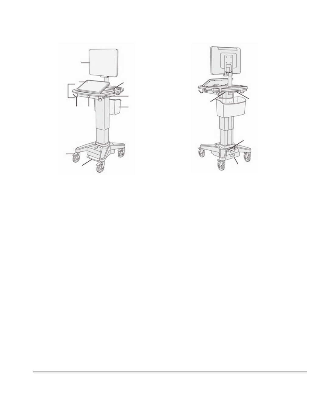
Figure 2-1 X-Porte front view Figure 2-2 X-Porte rear view
1
2
3
4
5
6
7
8
9
10
1
2
3
4
1. Clinical monitor, 2. Touch panel, 3. Platform,
4. Hook (4), 5. Transducer connector, 6. Locking
wheel (4), 7. Height-adjustment pedal,
1. Ports on dock, 2. Power cord
connector, 3. Battery charge
indicator, 4. Ports on dock
8. Basket, 9. USB ports (3),10. Power button
A license key is required to activate the software. See “Software licensing” on page 7-2.
Basic operating steps
1 Connect a transducer. See “Connecting transducers” on page 2-11.
2 Turn on the system. See “Turning on the system” on page 2-3.
3 Select the transducer and exam type (or use the default selections). See “Selecting a transducer and
exam type” on page 2-14.
4 (Optional) Enter patient information. See “Entering patient information” on page 4-31.
5 Scan. See “Imaging modes” on page 4-1.
2-2 Getting started

Accessories and peripherals
The system supports various accessories and peripherals. See “Compatible accessories and peripherals”
on page 9-12.
Preparing the system
Turning on the system
WAR NI NG S Verify that the hospital supply voltage corresponds to the power supply voltage
range.
Plug the system only into a grounded hospital-grade outlet.
Use only power cords provided by FUJIFILM SonoSite with the system.
Cautions Do not use the system if an error message appears on the clinical monitor. Note
the error code and turn off the system. Call FUJIFILM SonoSite or your local
representative.
When using AC power, position the system to allow easy access to disconnect it.
To turn on the system
The system can be powered by the internal battery or by AC power.
1 If you are operating the system using AC power, connect the AC power cord to the stand, and then
connect the AC power cord to a hospital-grade outlet.
2 Press the power button.
The power button turns green when the system is ready for scanning.
If the system does not maintain expected battery charge, or if the battery icon on the clinical monitor does
not display the battery charge status, disconnect and reconnect the system to AC power.
Connect the system to AC power to maintain battery charge, especially if the system will not be used for
several days.
To connect the system to AC power (battery charge maintenance)
1 Turn off the system.
2 Disconnect the system from AC power.
Getting started 2-3

3 Check the battery switches; ensure that all three switches are depressed to the ʘ symbol, which is the
ON position.
Note The system will not charge and maintain the batteries if the battery switches are
depressed to the ·O symbol, which is the OFF position.
4 Reconnect the system to AC power.
The battery charge indicator at the base of the stand blinks green, and the battery icon on the clinical
monitor displays the battery charging state.
To turn off the system
Note If the system appears unresponsive, wait several minutes before restarting it.
Restarting the system while it is performing data-intensive background
activities, such as transferring patient files, can result in loss of patient data. To
power down an unresponsive system, press and hold the power button until the
system shuts down. This procedure may take 5 seconds or longer.
Press the power button.
The system will power down when your data is safe. Any in-progress transfers will complete when power
is restored.
Adjusting the height and angle
WA RN IN G S Lock the wheels whenever the system is unattended or stationary.
To avoid possible injury from an unexpected clinical monitor collapse during
system transport, collapse the clinical monitor before system transport (see “To
collapse the clinical monitor” on page 2-5).
To raise or lower the platform
While pressing down the height-adjustment pedal, grasp both sides of the platform and push down or
pull up to the desired height.
To lock a wheel
Press down the lever on the wheel.
To unlock the wheel, press up on the bottom of the lever.
To adjust the clinical monitor angle
Grasping the clinical monitor on both sides, tilt or rotate it.
2-4 Getting started
To adjust the touch-panel angle
Grasping the sides of the touch panel, pull it forward or push it backward to the desired angle.
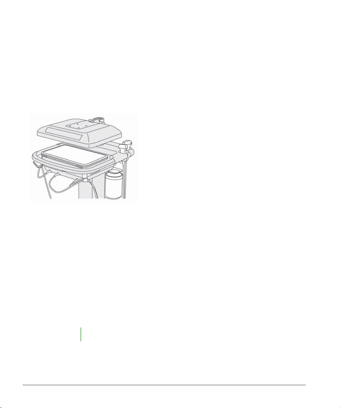
To collapse the clinical monitor
Always collapse the clinical monitor before system transport.
1 Adjust the touch panel angle to the lowest position.
2 Grasping the clinical monitor on both sides, align it squarely above the touch panel.
3 Fold the clinical monitor downward over the touch panel. Refer to Figure 2-3 on page 2-5.
Figure 2-3 Clinical monitor collapsed for system transport
USB devices
You can use the USB ports on the system for connecting devices such as a USB printer or a USB memory
stick. For a list of supported devices, see “Compatible accessories and peripherals” on page 9-12.
One of the USB ports at the back of the system is for DVR recording only. See “Ports” on page 2-20 and
“DVR recording” on page 4-47.
USB memory sticks
You can use a USB memory stick to export patient exams, import and export logs and setup configurations,
and to import custom obstetric calculation tables.
Note The system does not support software-encrypted USB memory sticks.
Getting started 2-5

Cautions To avoid damaging the USB memory stick and losing patient data from it, observe
the following:
Do not remove the USB memory stick or turn off the ultrasound system
while the system is exporting.
Do not bump o r otherwise apply pre ssure to the USB memory stick while it is
in a USB port on the ultrasound system. The connector could break.
If the USB icon does not appear in the system status area on the clinical
monitor, the USB memory stick may be defective or software-encrypted.
Replace the USB memory stick.
To connect a USB memory stick for importing or exporting
Insert the USB memory stick into a USB port (see “About the system” on page 2-1).
The USB memory stick is ready when the USB icon appears onscreen.
To view information about the device, see “USB settings” on page 3-36.
To disconnect a USB memory stick
Disconnecting the USB memory stick while the system is exporting to it may cause the exported files to be
corrupted or incomplete.
1 If exporting, wait at least five seconds after the USB animation icon stops.
2 Remove the USB memory stick from the port.
General interaction
Clinical monitor
WA RN I NG S FUJIFILM SonoSite does not recommend using a monitor other than the clinical
monitor provided by FUJIFILM SonoSite. Only the images presented on the
clinical monitor are validated for the intended use of the device.
Do not use a monitor connected through the external VGA or digital video out
for medical diagnosis.
2-6 Getting started
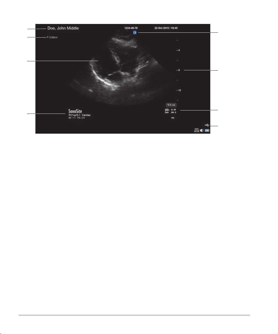
The clinical monitor displays the ultrasound image as well as details about the exam and system status.
1
2
8
4
5
6
3
7
Figure 2-4 Clinical monitor layout
1
Patient header 5 System status area
2
Measurement and calculation area 6 Imaging mode or modes, controls selected
3
Ultrasound image 7 Depth scale
4
Selected transducer, exam type, and MI
8 Orientation marker
and TI values
Getting started 2-7

VGA or digital video output
WA RN I NG S To avoid possible electrical shock or electromagnetic interference, verify proper
operation and compliance with relevant safety standards for all equipment
before clinical use. Connecting additional equipment to the ultrasound system
constitutes configuring a medical system. FUJIFILM SonoSite recommends
verifying that the system, all combinations of equipment, and accessories
connected to the ultrasound system comply with relevant installation
requirements and safety standards.
For safety, FUJIFILM SonoSite recommends isolating auxiliary video connections
with external devices; for example, optical or wireless interface adapters. Check
the electrical safety of your system with a trained biomedical engineer prior to
use.
WA RN I NG S FUJIFILM SonoSite does not recommend using a monitor other than the clinical
monitor provided by FUJIFILM SonoSite. Only the images presented on the
clinical monitor are validated for the intended use of the device.
Do not use a monitor connected through the external VGA or digital video out
for medical diagnosis.
Resolution
VGA video output resolution is 1280 x 800 at 60 Hz (non-interlaced), Reduced Blanking.
Digital video output resolution is 1920 x 1080 at 60 Hz.
Note Digital video output is only available on the second monitor configuration. See
“Clinical monitor” on page 9-24.
Touch panel
The touch panel is where you adjust settings; select the exam type, transducer, and imaging mode; enter
patient information; and more. As you adjust the image settings or controls, the results appear on the clinical
monitor. When an image is frozen, the touch panel displays an outline of the image.
You interact with the touch panel the same as with many other touchscreen devices:
Swipe: Move your finger quickly across the panel. Faster than dragging.
Drag: Move one or two fingers across the panel, usually to move an object from one location to another.
Ta p: Quickly touch the panel once; for example, to activate a control.
Double-tap: Quickly touch the panel twice with one or more fingers.
Pinch or spread: Slide two fingers together or apart on the panel.
2-8 Getting started

Use these gestures to perform these actions:
Table 2-1: Gestures and actions
Gesture Action
Swipe Steer D-line (linear transducers only)
Steer color box (linear transducers only)
Scroll through pages in forms, such as the patient form,
worksheets, and thumbnails in Review
Select previous or next images in full-screen Review
Drag Adjust depth or gain
Move color or zoom box
Move calipers
Move D-line or M-line
Move Doppler baseline
With two or more fingers, drag anywhere on the touch panel to
move or resize the active object, such as the Color box or the
Doppler gate
Move depth marker in biopsy guide
Change the D-line angle selection
Move labels, pictograms, and transducer marker
Move through frames in the cine buffer
Move controls to the Controls bar
Pan a frozen zoomed 2D image (panning is disabled if
measurements or labels exist on the frozen zoomed image)
Unfreeze a frozen image by dragging the Slide to Unfreeze
slider
Getting started 2-9
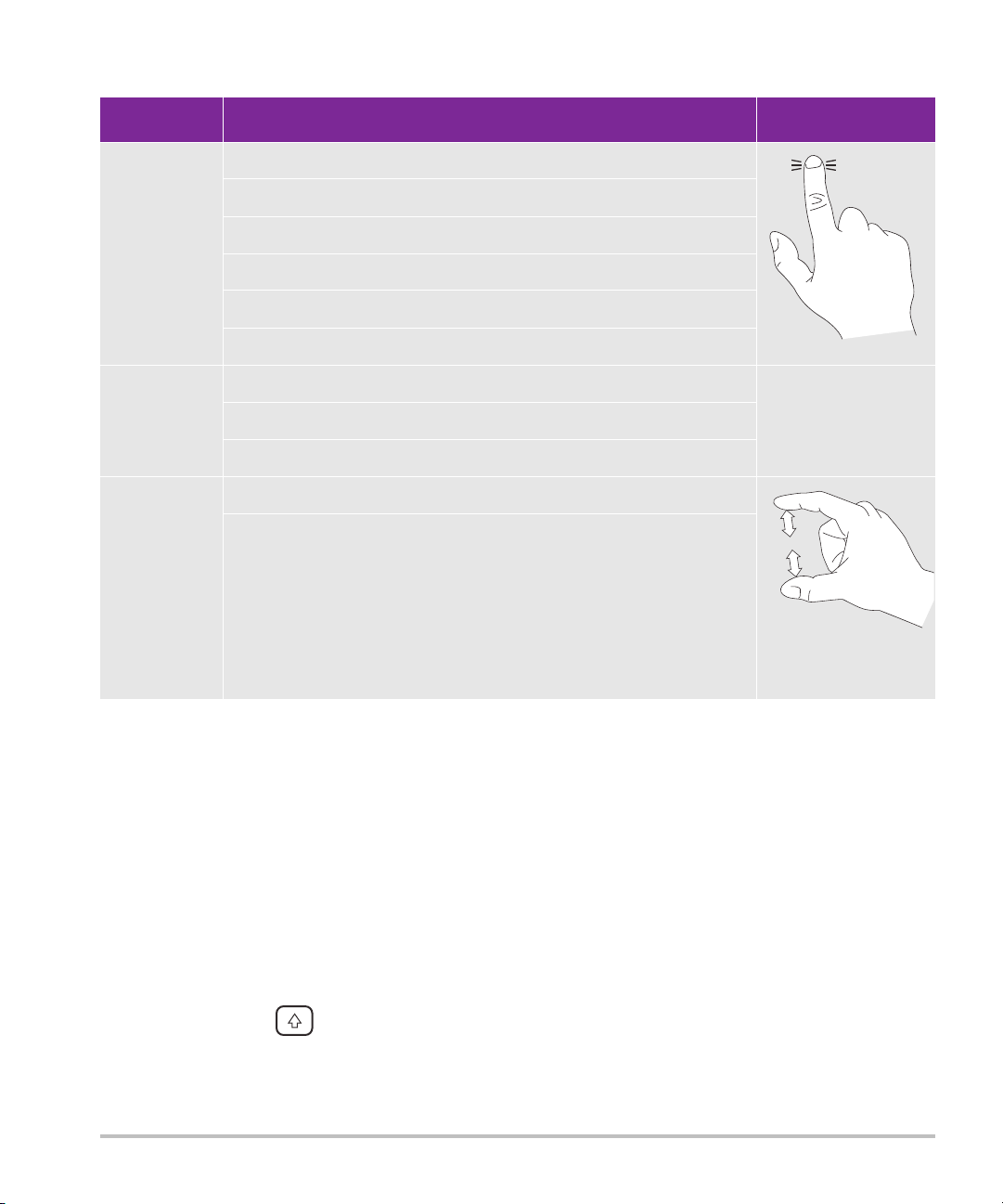
Table 2-1: Gestures and actions (continued)
Gesture Action
Ta p Freeze
Adjust depth
Select calipers
Select image in dual
Select mode in split screen (2D, D-line, or Doppler trace)
Select control
Double-tap With two or more fingers, double-tap to freeze or unfreeze
Double-tap with one finger in the zoom box to zoom
Double-tap with one finger on a live zoomed image to unzoom
Pinch or
spread
Sample volume size
Resize color or zoom box
Onscreen keyboard
You can enter text into text boxes (for example, on the patient form) using the onscreen keyboard.
To enter text using the onscreen keyboard
1 Tap a text box (for example, in the patient form).
The onscreen keyboard appears.
2 Tap keys as needed.
Tap and hold the alpha keys to reveal options for selecting accented versions of the characters
Tap the shift key to change alphabet keys to uppercase characters
Ta p Previous to jump to previous text box
2-10 Getting started

Ta p Next to advance to next text box
123#?
123#?
X
Tap to display keys for numbers, symbols, and special characters
Note
Tap to close the keyboard
Tap to start a new line or advance to next text box
Tap to delete a character on the left side of pointer
To display international characters on the keyboard, tap , and then tap the
shift key.
Preparing transducers
WA RN I N G S Some transducer sheaths contain natural rubber latex and talc, which can cause
allergic reactions in some individuals. FUJIFILM SonoSite recommends that you
identify your latex and talc-sensitive patients and be prepared to treat allergic
reactions promptly.
Some gels and sterilants can cause an allergic reaction on some individuals.
Cautions To avoid damage to the transducer, use only gels recommended by FUJIFILM
SonoSite. Using other gels can damage the transducer and void the warranty. If
you have questions about gel compatibility, contact FUJIFILM SonoSite or your
local representative.
Clean transducers after each use (see “Determining the required cleaning
and disinfecting level” on page 8-2).
Connecting transducers
This section provides instructions to connect a transducer, with or without the Triple Transducer Connect
(TTC), as well as instructions to remove a transducer.
To connect a transducer to the TTC
The TTC is a three-transducer module that lets you simultaneously connect up to three transducers to the
ultrasound system. The TTC is standard with the system.
1 Pull the transducer latch handle up, and rotate it clockwise.
Getting started 2-11
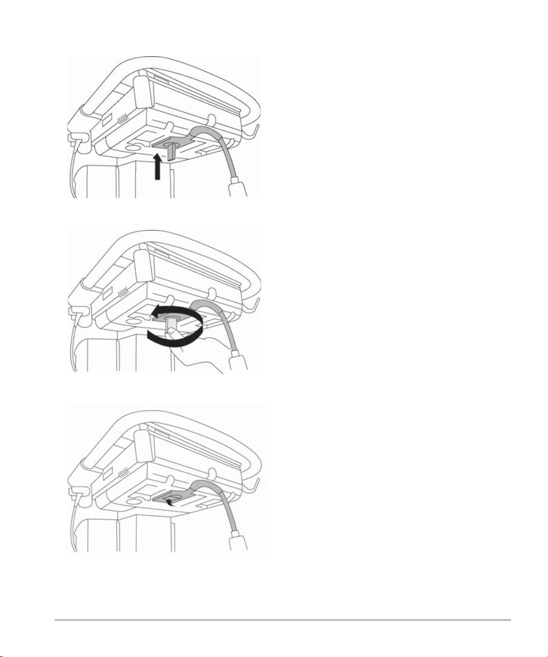
2 Insert the transducer connector into one of the three TTC connector ports on the bottom of the TTC.
3 Make sure that the connector is firmly seated, and then turn the latch handle counterclockwise.
4 Press the latch handle up, securing the transducer connector to the TTC.
2-12 Getting started
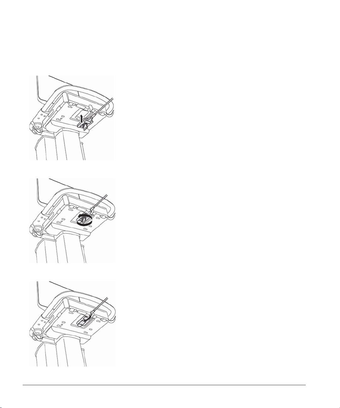
To connect a transducer to the system (without a TTC)
If the TTC is not installed on your system, you can connect one transducer directly to the system.
1 Pull the transducer latch up, and rotate it clockwise.
2 Insert the transducer connector into the transducer port underneath the stand platform.
3 Make sure that the connector is firmly seated, and then turn the latch handle counterclockwise.
4 Press the latch up, securing the transducer connector to the system.
Getting started 2-13

To remove a transducer
Caution To avoid equipment damage that could lead to image quality degradation, do not
disconnect a transducer while it is in use. Either freeze the image or switch to
another transducer before disconnecting.
1 Pull the transducer latch up, and rotate it clockwise.
2 Pull the transducer connector away from the system.
Selecting a transducer and exam type
WARN I N G To prevent misdiagnosis or harm to the patient, use the correct transducer for
the application. The diagnostic capability differs for each transducer, exam type,
and imaging mode. Transducers are developed to specific criteria depending on
their physical application. These criteria include biocompatibility requirements.
Understand the system's capabilities prior to use.
Before scanning, select a transducer and exam type.
To select a transducer and exam type
1 Do one of the following:
On the start select screen, tap SELECT if present. To set up the start select screen, see “User profile
settings” on page 3-32.
Ta p TRANSDUCERS & EXAMS at the top of the touch panel.
Cards for the available transducers appear (see “Connecting transducers” on page 2-11).
2 On the card for the appropriate transducer, do one of the following:
Double-tap the exam type.
Tap the exam type, and then tap SCAN, or tap Cancel to cancel.
Scrolling the list of exam types displays any hidden items.
You can also select the exam type on the patient form (see “Entering patient information” on
page 4-31).
Related topics
Intended uses ........................................................................................................................................................... 2-24
2-14 Getting started
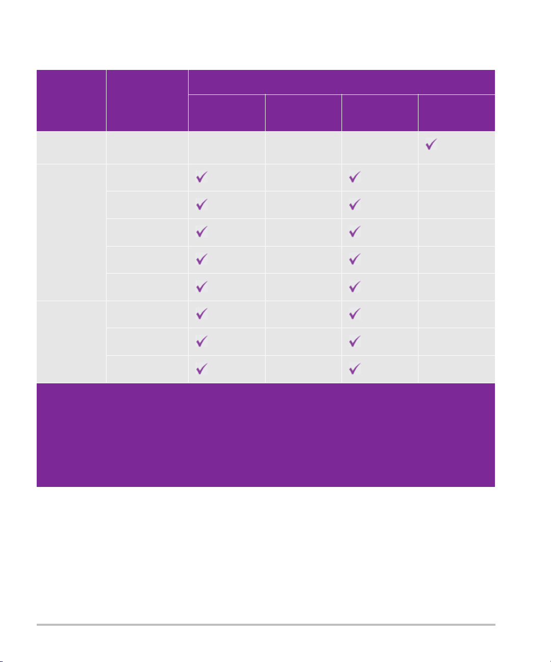
Table 2-2: Imaging modes and exam types on transducers
Imaging mode
Transducer Exam type
D2xp
c
Cardiac — — —
2D
M Mode
Color
a
PW Doppler
b
CW Doppler
C11xp Abdomen CVD, CPD —
Arterial CVD, CPD —
Neonatal CVD, CPD —
Nerve CVD, CPD —
Venous CVD, CPD —
C35xp
d
Abdomen CVD, CPD —
Musculoskeletal CVD, CPD —
Nerve CVD, CPD —
a
Color Doppler Variance (Var) is available in the cardiac exam only. Color Power Doppler (CPD) is available in all
exams except the cardiac exam type. Color Velocity Doppler (CVD) is supported on all transducers except for
D2xp.
b
For the cardiac exam type, PW TDI is also available.
c
Make sure you unscrew the D2xp stabilization handle before moving the transducer from its parked position.
d
Needle guide-capable. For more information, refer to Using CIVCO Products with FUJIFILM SonoSite Systems.
e
For more information refer to the TEExp Transducer User Guide, included with the TEExp transducer.
Getting started 2-15

Table 2-2: Imaging modes and exam types on transducers (continued)
Imaging mode
Transducer Exam type
C60xp
d
Abdomen CVD, CPD —
Gynecology CVD, CPD —
Musculoskeletal CVD, CPD —
Nerve CVD, CPD —
Obstetrics CVD, CPD —
d
HFL38xp
Arterial CVD, CPD —
Breast CVD, CPD —
Lung CVD, CPD —
Musculoskeletal CVD, CPD —
Nerve CVD, CPD —
2D
M Mode
Color
a
PW Doppler
b
CW Doppler
Small Parts CVD, CPD —
Venous CVD, CPD —
a
Color Doppler Variance (Var) is available in the cardiac exam only. Color Power Doppler (CPD) is available in all
exams except the cardiac exam type. Color Velocity Doppler (CVD) is supported on all transducers except for
D2xp.
b
For the cardiac exam type, PW TDI is also available.
c
Make sure you unscrew the D2xp stabilization handle before moving the transducer from its parked position.
d
Needle guide-capable. For more information, refer to Using CIVCO Products with FUJIFILM SonoSite Systems.
e
For more information refer to the TEExp Transducer User Guide, included with the TEExp transducer.
2-16 Getting started
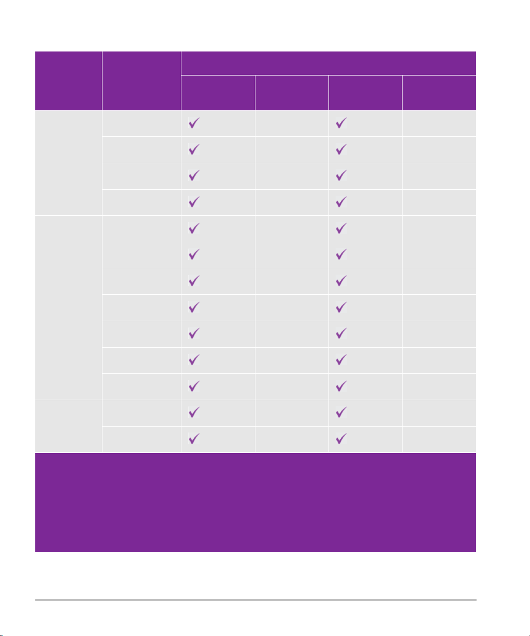
Table 2-2: Imaging modes and exam types on transducers (continued)
Imaging mode
Transducer Exam type
d
HFL50xp
Breast CVD, CPD —
2D
M Mode
Color
a
PW Doppler
b
CW Doppler
Musculoskeletal CVD, CPD —
Nerve CVD, CPD —
Small Parts CVD, CPD —
HSL25xp Arterial CVD, CPD —
Lung CVD, CPD —
Musculoskeletal CVD, CPD —
Nerve CVD, CPD —
Ophthalmic CVD, CPD
Superficial CVD, CPD —
Venous CVD, CPD —
ICTxp
d
Gynecology CVD, CPD —
Obstetrics CVD, CPD —
a
Color Doppler Variance (Var) is available in the cardiac exam only. Color Power Doppler (CPD) is available in all
exams except the cardiac exam type. Color Velocity Doppler (CVD) is supported on all transducers except for
D2xp.
b
For the cardiac exam type, PW TDI is also available.
c
Make sure you unscrew the D2xp stabilization handle before moving the transducer from its parked position.
d
Needle guide-capable. For more information, refer to Using CIVCO Products with FUJIFILM SonoSite Systems.
e
For more information refer to the TEExp Transducer User Guide, included with the TEExp transducer.
Getting started 2-17
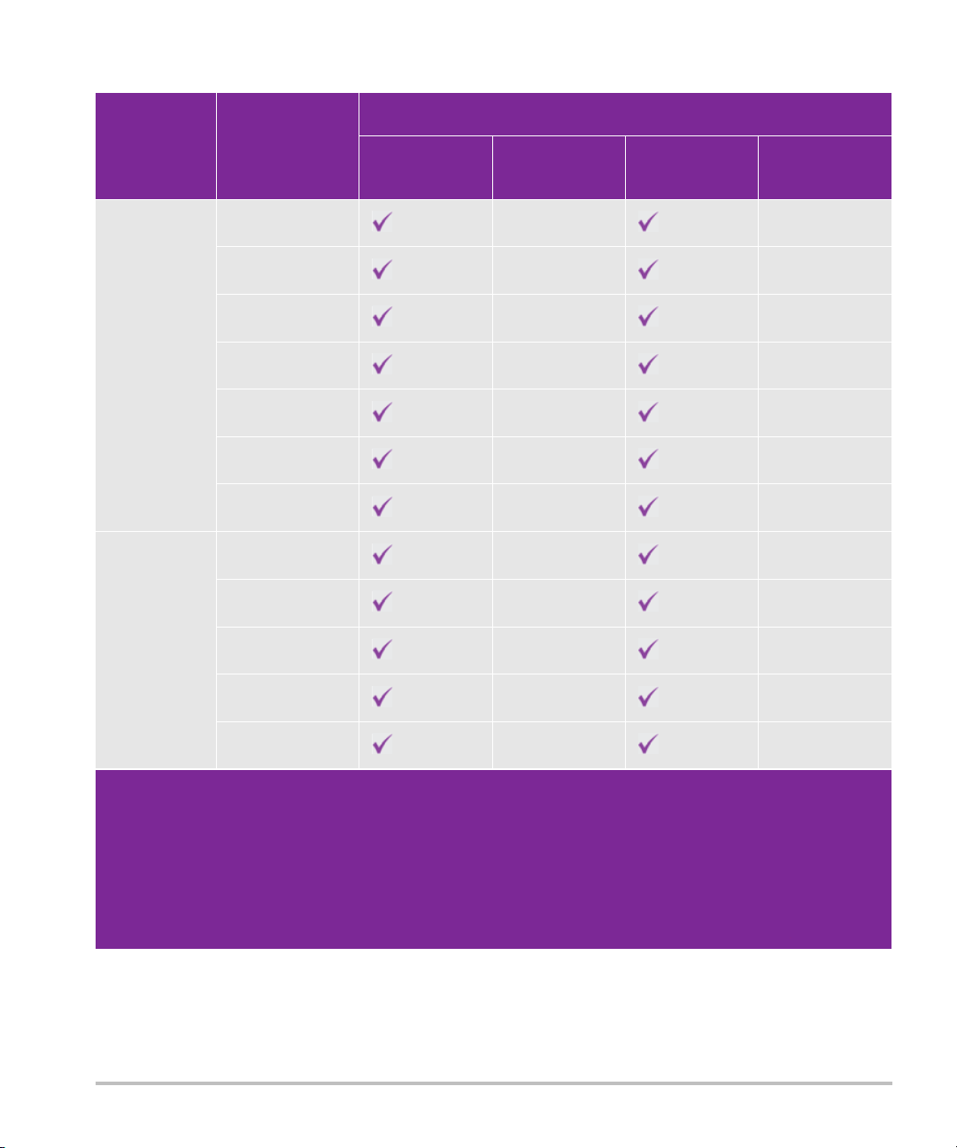
Table 2-2: Imaging modes and exam types on transducers (continued)
Imaging mode
Transducer Exam type
L25xp
d
Arterial CVD, CPD —
Lung CVD, CPD —
Musculoskeletal CVD, CPD —
Nerve CVD, CPD —
Ophthalmic CVD, CPD —
Superficial CVD, CPD —
Venous CVD, CPD —
L38xp
d
Arterial CVD, CPD —
Lung CVD, CPD —
Nerve CVD, CPD —
2D
M Mode
Color
a
PW Doppler
b
CW Doppler
Small Parts CVD, CPD —
Venous CVD, CPD —
a
Color Doppler Variance (Var) is available in the cardiac exam only. Color Power Doppler (CPD) is available in all
exams except the cardiac exam type. Color Velocity Doppler (CVD) is supported on all transducers except for
D2xp.
b
For the cardiac exam type, PW TDI is also available.
c
Make sure you unscrew the D2xp stabilization handle before moving the transducer from its parked position.
d
Needle guide-capable. For more information, refer to Using CIVCO Products with FUJIFILM SonoSite Systems.
e
For more information refer to the TEExp Transducer User Guide, included with the TEExp transducer.
2-18 Getting started

Table 2-2: Imaging modes and exam types on transducers (continued)
Imaging mode
Transducer Exam type
P10xp
d
Abdomen CVD, CPD —
Cardiac CVD, Var
Neonatal CVD, CPD —
P21xp
d
Abdomen CVD, CPD —
Cardiac CVD, Var
Lung CVD, CPD —
Obstetrics CVD, CPD —
Orbital CVD, CPD —
Transcranial CVD, CPD —
TEExp
e
Cardiac CVD, Var
2D
M Mode
Color
a
PW Doppler
b
CW Doppler
a
Color Doppler Variance (Var) is available in the cardiac exam only. Color Power Doppler (CPD) is available in all
exams except the cardiac exam type. Color Velocity Doppler (CVD) is supported on all transducers except for
D2xp.
b
For the cardiac exam type, PW TDI is also available.
c
Make sure you unscrew the D2xp stabilization handle before moving the transducer from its parked position.
d
Needle guide-capable. For more information, refer to Using CIVCO Products with FUJIFILM SonoSite Systems.
e
For more information refer to the TEExp Transducer User Guide, included with the TEExp transducer.
Gel
Use acoustic coupling gel on the transducer during exams. Although most gels provide suitable acoustic
coupling, some gels are incompatible with some transducer materials. FUJIFILM SonoSite recommends
Aquasonic gel and provides a sample with the system.
Getting started 2-19
For general use, apply a liberal amount of gel between the transducer and the body. For interventional use,
1
2
34 7
8
5
6
apply a transducer sheath.
Sheaths
WARN I N G Use market-cleared, sterile transducer sheaths and sterile coupling gel for
transrectal, transvaginal, or guided-needle procedures. Do not apply the
transducer sheath and coupling gel until you are ready to perform the
procedure. After use, remove and discard the single-use sheath, and clean and
disinfect the transducer using a FUJIFILM SonoSite-recommended disinfectant.
See the cleaners and disinfection document available at www.sonosite.com for
a complete list of the most current cleaners and disinfectants.
To apply a transducer sheath
1 Place gel inside the sheath. Make sure that the gel is at the end of the sheath.
2 Insert the transducer into the sheath.
3 Pull the sheath over the transducer and cable until the sheath is fully extended.
4 Secure the sheath using the bands supplied with the sheath.
5 Check for and eliminate air bubbles between the face of the transducer and the sheath.
Air bubbles between the face of the transducer and the sheath may affect the ultrasound image.
6 Inspect the sheath to ensure that there are no holes or tears.
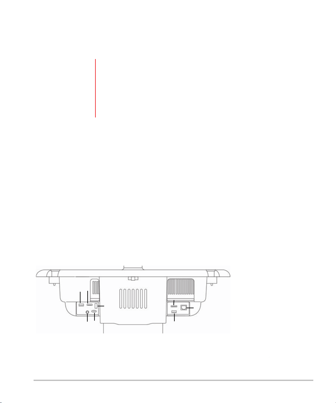
Ports
Two dock configurations are now available. The dock provides ports for various applications (see Figure 2-5
on page 2-20 and Figure 2-6 on page 2-21).
Figure 2-5 Back of system with first dock configuration: 1. USB 2. Digital video in 3. Audio in 4. MicroSD -
DVR software upgrade 5. USB storage - DVR 6. E-SATA (unsupported) 7. USB 8. Ethernet
2-20 Getting started
 Loading...