

FujiFilm SonoSite S Series User Manual Supplement

S Series Ultrasound System
User Guide Supplement P13895-06


User Guide Supplement P13895-06
Ergänzung zum Benutzerhandbuch P13895-06
Suplemento del Manual para el usuario P13895-06
Supplément au guide d’utilisation P13895-06
English Deutsch Español Français Italiano PortuguêsFrançais
Supplemento al Manuale dell’utente P13895-06
Suplemento do Manual do Usuário P13895-06
Supplement bij gebruikershandleiding P13895-06
Nederlands


Tillæg til brugervejledning P13895-06
Vedlegg til brukerveiledning P13895-06
Tillägg till användarhandbok P13895-06
Συμπλήρωμα στον οδηγό χρήσης P13895-06
Dansk Norsk Svenska Ελληνικά Русский Türkçe
Дополнение к руководству пользователя
P13895-06
Kullanıcı Kılavuzu Eki P13895-06
用户指南补充说明 P13895-06
使用者手冊補充說明 P13895-06
简体中文 繁體中文

Manufacturer
FUJIFILM SonoSite, Inc.
21919 30th Drive SE
Bothell, WA 98021 USA
T: 1-888-482-9449 or 1-425-951-1200
F: 1-425-951-1201
EC Authorized Representative
FUJIFILM SonoSite B.V.
Joop Geesinkweg 140
1114 AB Amsterdam,
The Netherlands
Australia Sponsor
FUJIFILM SonoSite Australasia Pty Ltd
114 Old Pittwater Road
BROOKVALE, NSW, 2100
Australia
Caution:
S Series, SonoMBe, SonoSite, and the SonoSite logo are registered and unregistered trademarks of FUJIFILM SonoSite, Inc. in various
jurisdictions. FUJIFILM is a registered trademark of FUJIFILM Corporation. Value from Innovation is a trademark of FUJIFILM Holdings
America Corporation.
All other trademarks are the property of their respective owners.
Patents: US 8,376,103; US 8,216,146; US 8,213,467; US 8,137,278; US 8,066,642; US 7,978,461; US 7,804,970; US 7,740,586; US 7,686,766; US
7,591,786; US 7,588,541; US 7,534,211; US 7,449,640; US 7,169,108; US 6,962,566; US 6,648,826; US 6,569,101; US 6,471,651; US 6,416,475;
US 6,383,139; US 6,371,918; US 6,364,839; US 6,135,961; US 5,893,363; US 5,817,024; US 5,782,769; US 5,722,412; USD592,750; USD591,423;
AU 727381; AU 730822; CA 2,371,711; CA 2,372,152; CA 2,373,065; CN 97113678.5; CN 98106133.8; CN 200830007734.8; EP 0875203; EP
0881492; EP 1175713; EP 1180970; EP 1180971; EP 1552792; EP 1589878; JP 4696150; KR 528102; and KR 532359.
United States federal law restricts this device to sale by or on the order of a physician.
P13895-06 06/2019
Copyright 2019 by SonoSite, Inc.
All rights reserved. Printed in the USA.
ii

S Series Ultrasound System
User Guide Supplement P13895-06
Introduction .............................................................................................................................1
Imaging .....................................................................................................................................1
Safety .........................................................................................................................................4
Introduction
This user guide supplement does the following:
• Updates acoustic output information for the S Series™ ultrasound system
English Deutsch Español Français Italiano Português
• Describes SonoMBe
transducers:
• C60x/5-2 MHz
• HFL38x/13-6 MHz
• HFL50x/15-6 MHz
• L25x/13-6 MHz
• L38xi/10-5 MHz
Imaging
2D imaging
WARNING:
™ multi-beam imaging, enhanced (MBe), available on the following
To avoid incorrect needle placement when MBe is on:
• Using movement and fluid injection, verify the needle-tip location and trajectory.
MBe enhances linear structures within a selected angle range on the ultrasound
plane. Linear structures outside the selected angle range or the ultrasound
plane
—such as a bent needle—may be less apparent.
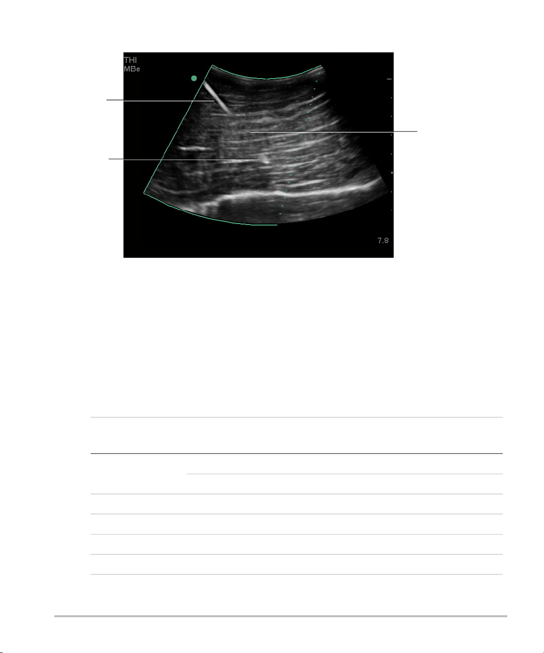
• Note that linear structures are enhanced only in an outlined portion of the image.
The area outside the outline remains unchanged. (See Figure 2.)
• Note that the beam divergence of a curved array transducer may prevent a
segment of the needle shaft from showing in the image. (See Figure 3.) The needle
tip may not show.
Nederlands
1

2D controls
MBe Turns on SonoMBe imaging, which enhances linear structures within a selected angle
range and can facilitate needle guidance during catheter placement and nerve-block
procedures. A three- or four-sided outline indicates the affected area. (See Figure 2.)
For curved array transducers, MBe can help identify the direction of the needle,
although only segments of the needle shaft may show in the image. (See Figure 3.)
Use movement and fluid injection to help verify the needle-tip location.
Use a 17-gauge to 25-gauge needle (recommended). Enhancement results can
depend on the type and brand of needle used. For more information, consult the
medical literature on needle visibility in ultrasound-guided procedures.
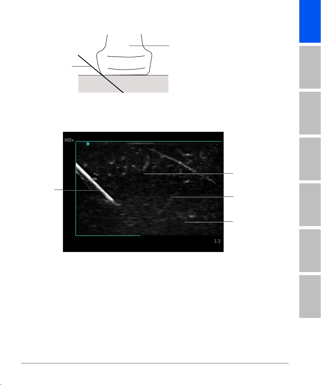
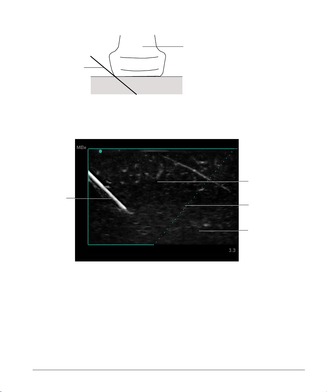
You can angle the needle up to 50° from the transducer surface. (See Figure 1.) Beyond
50°, the needle may be less enhanced. (MBe has little or no benefit to out-of-plane
procedures. MBe is intended for in-plane procedures only.)
Avoid setting the gain too high, as unnecessarily high gain can cause artifacts in the
image. Also, respiratory and cardiac movement in the image may cause bright
pulsating artifacts.
When MBe is on, additional controls are available:
• L/R Flip flips the affected area (the outline) horizontally on the image.
For reorienting the entire image, use the orientation control .
• Shallow, Medium, or Steep sets the outline’s sloped edge, which is indicated by a
dotted line.
• Linear transducer: Use whichever setting provides best perpendicularity to the
dotted line. Within the affected area, the more perpendicular that a linear
structure is to the dotted line, the more it is enhanced. Similarly, the less
perpendicular (and more parallel) that a linear structure is to the dotted line, the
less it is enhanced.
• Curved array transducer: For a linear structure angled 30° or less from the
transducer surface, use Shallow for best enhancement. For a linear structure
angled 30-40°, use Medium. For a linear structure angled 40° or greater, use
Steep.
The control key of the current selection is outlined.
• Off turns off MBe. Temporarily turning off MBe can help you identify artifacts and
other structures not of interest.
• Back returns to the previous screen. If MBe is on, MBe is highlighted green and MBe
appears in the mode data area. Pressing MBe again redisplays the MBe controls.
Available in Breast, Musculoskeletal, Nerve, Small Parts, Vascular (L25x only), and
Venous (L25x only) exams and in full-screen imaging only. If MBe is on, the MB control
is unavailable.
2
0 - 50°
2
1
Figure 1:For best results, angle the needle only up to 50° from the transducer surface:
1 Needle 2 Transducer
2
English Deutsch Español Français Italiano Português
1
Figure 2:Image with MBe on (linear transducer)
1 Needle
2 Outlined area affected by MBe
3 Dotted line
4 Unenhanced area
3
4
Nederlands
3
1
2
Safety
Output display
3
Figure 3:With a curved array transducer, only segments of the needle shaft may show:
1 Upper needle shaft
2 Needle tip
3 Unshown segment of needle shaft
(unshown segment or segments depend
on specific image)
Table 1: TI or MI 1.0
Transducer Model Index
2D/
M Mode
CPD/
Color
PW
Doppler
CW
Doppler
HFL38x MI Yes Yes Yes —
TIC, TIB, or TIS No Yes Yes —
HFL50x MI Yes Yes Yes —
TIC, TIB, or TIS No No Yes —
L25x MI Yes No No —
TIC, TIB, or TIS No No Yes —
4

Acoustic output tables
Table 2: Transducer Model: HFL38x/13-6 Operating Mode: 2D
TIS TIB
English Deutsch Español Français Italiano Português
A
aprt
Non-scan
1 A
aprt
Non-scan
TIC
>1
Index Label MI
Scan
Global Maximum Index Value 1.1 (a) — — — (b)
p
r.3
W
0
min of [W
z
1
z
bp
z
sp
z@PII
Parameter
Associated Acoustic
.3max
deq(zsp) (cm) —
f
c
Dim of A
.3(z1
aprt
),I
TA.3(z1
)] (mW) —
(MPa) 2.56
(mW) # — — #
(cm) —
(cm) —
(cm) —
1.2
(MHz) 5.33 # — — — #
X (cm) # — — — #
Y (cm) # — — — #
PD (µsec) 0.525
PRF (Hz) 2450
pr@PII
max
deq@Pll
Other
Focal Length FLx (cm) # — — #
max
Information
I
@MI
PA.3
max
Control 1: Exam Type Nrv/Bre/
(MPa) 3.19
(cm) —
FL
(cm) # — — #
y
(W/cm2)
325.3
— — — — —
SmP/Msk
Control 2: Optimization Any — — — — —
Control 3: Depth 3.3 cm — — — — —
Control
Operating
Conditions
Control 4: MBe On — — — — —
Nederlands
(a) This index is not required for this operating mode; value is <1.
(b) This transducer is not intended for transcranial or neonatal cephalic uses.
# No data are reported for this operating condition since the global maximum index value is not reported
for the reason listed. (Reference Global Maximum Index Value line.)
— Data are not applicable for this transducer/mode.
5

Table 3: Transducer Model: HFL38x Operating Mode: CPD/Color
TIS TIB
A
aprt
Non-scan
1 A
aprt
>1
Non-
scan
TIC
Index Label MI
Scan
Global Maximum Index Value 1.1 1.0 — — — (b)
p
r.3
W
0
min of [W
z
1
z
bp
z
sp
Parameter
deq(zsp) (cm) —
Associated Acoustic
f
c
Dim of A
.3(z1
aprt
),I
TA.3(z1
)] (mW) —
(MPa) 2.556
(mW) 37.69 — — #
(cm) —
(cm) —
(cm) 1.2 —
(MHz) 5.328 5.324 — — — #
X (cm) 0.44 — — — #
Y (cm) 0.4 — — — #
PD (µsec) 0.525
PRF (Hz) 2597
pr@PII
max
deq@Pll
Other
Focal Length FLx (cm) 1.32 — — #
max
Information
I
@MI
PA.3
max
(MPa) 3.187
(cm) —
FL
(cm) 2.5 — — #
y
(W/cm2)
325.5
Control 1: Mode Color Color — — — —
Control 2: Exam Type Any Ven — — — —
Control 3: Optimization/Depth/PRF Low/
3.3 cm/
Control
Operating
Conditions
Control 4: Color Box Position/Size Any Top/
Any
Med/
2.7 cm/
2841
— — — —
— — — —
Short
(a) This index is not required for this operating mode; value is <1.
(b) This transducer is not intended for transcranial or neonatal cephalic uses.
# No data are reported for this operating condition since the global maximum index value is not reported
for the reason listed. (Reference Global Maximum Index Value line.)
— Data are not applicable for this transducer/mode.
6

Table 4: Transducer Model: HFL38x Operating Mode: PW Doppler
TIS TIB
English Deutsch Español Français Italiano Português
A
aprt
Non-scan
1 A
aprt
Non-scan
TIC
>1
Index Label MI
Scan
Global Maximum Index Value 1.0 — 1.1 — 2.0 (b)
p
r.3
W
0
min of [W
z
1
z
bp
z
sp
Parameter
deq(zsp) (cm) 0.33
Associated Acoustic
f
c
Dim of A
.3(z1
aprt
),I
TA.3(z1
)] (mW) —
(MPa) 2.37
(mW) — 43.01 43.01 #
(cm) —
(cm) —
(cm) 0.9 1.1
(MHz) 5.32 — 5.30 — 5.30 #
X (cm) — 1.04 — 1.04 #
Y (cm) — 0.4 — 0.4 #
PD (µsec) 1.29
PRF (Hz) 1008
pr@PII
max
deq@Pll
Other
Focal Length FLx (cm) — 3.72 — #
max
Information
I
@MI
PA.3
max
Control 1: Exam Type Bre/Vas
(MPa) 2.404
(cm) 0.21
FL
(cm) — 2.5 — #
y
(W/cm2)
323.35
Any Any
SmP/IMT
Control 2: Sample Volume 1 mm 1 mm 1 mm
Control 3: PRF 1008 6250 6250
Control
Operating
Conditions
Control 4: Sample Volume Position Zone 2 Zone 7 Zone 7
(a) This index is not required for this operating mode; value is <1.
(b) This transducer is not intended for transcranial or neonatal cephalic uses.
# No data are reported for this operating condition since the global maximum index value is not reported
for the reason listed. (Reference Global Maximum Index Value line.)
— Data are not applicable for this transducer/mode.
7
Nederlands

Table 5: Transducer Model: HFL50x Operating Mode: 2D
TIS TIB
A
aprt
Non-scan
1 A
aprt
Non-scan
TIC
>1
Index Label MI
Scan
Global Maximum Index Value 1.3 (a) — — — (b)
p
r.3
W
0
min of [W
z
1
z
bp
z
sp
z@PII
Parameter
Associated Acoustic
.3max
deq(zsp) (cm) —
f
c
Dim of A
.3(z1
aprt
),I
TA.3(z1
)] (mW) —
(MPa) 3.051
(mW) # — — #
(cm) —
(cm) —
(cm) —
1.2
(MHz) 5.36 # — — — #
X (cm) # — — — #
Y (cm) # — — — #
PD (µsec) 0.521
PRF (Hz) 2733
pr@PII
max
deq@Pll
Other
Focal Length FLx (cm) # — — #
max
Information
I
@MI
PA.3
max
(MPa) 3.81
(cm) —
FL
(cm) # — — #
y
(W/cm2)
493
Control 1: Exam Type Any — — — — —
Control 2: Optimization Any — — — — —
Control 3: Depth 3.3 — — — — —
Control
Operating
Conditions
Control 4: MBe On — — — — —
(a) This index is not required for this operating mode; value is <1.
(b) This transducer is not intended for transcranial or neonatal cephalic uses.
# No data are reported for this operating condition since the global maximum index value is not reported
for the reason listed. (Reference Global Maximum Index Value line.)
— Data are not applicable for this transducer/mode.
8
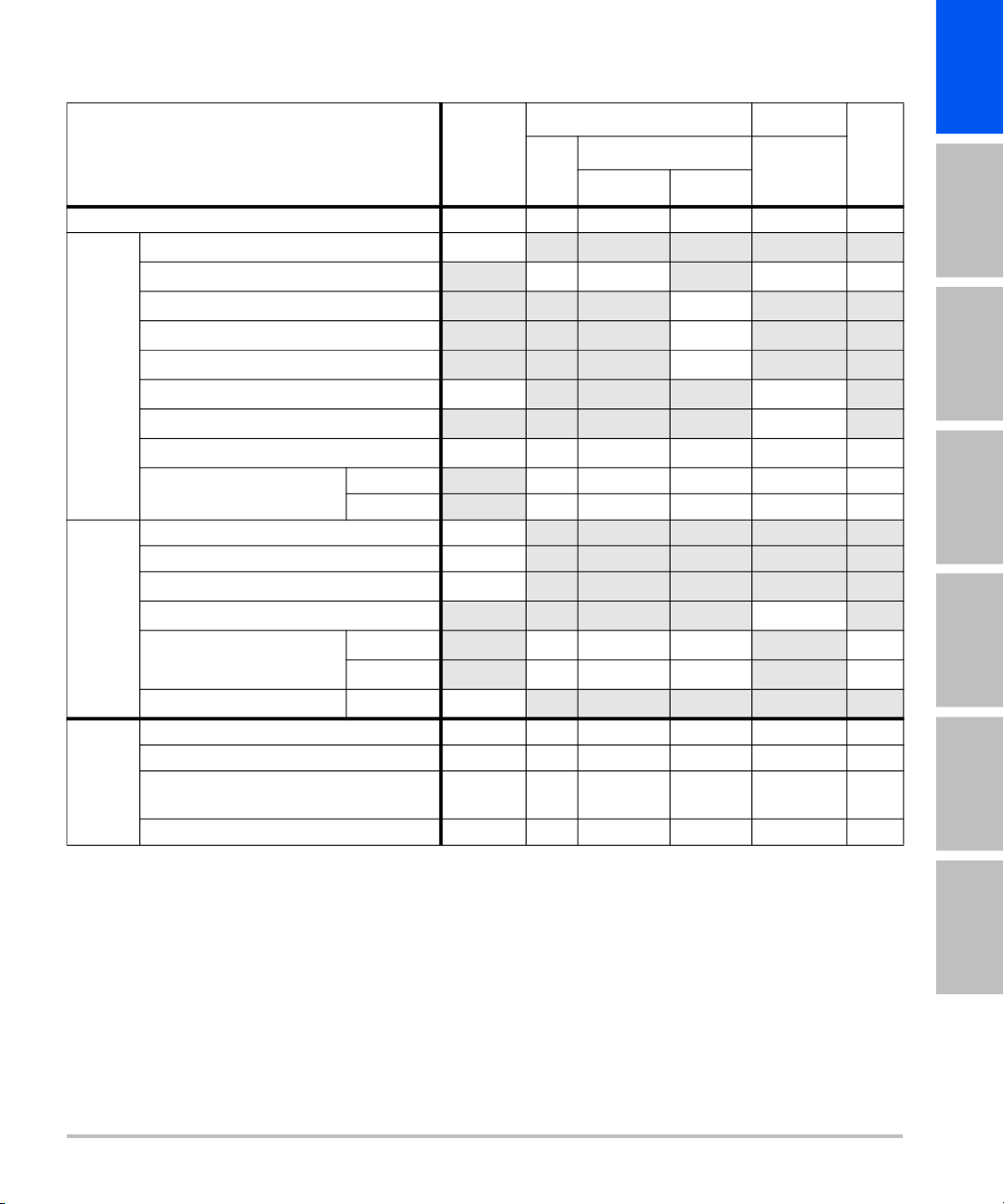
Table 6: Transducer Model: HFL50x Operating Mode: PW Doppler
TIS TIB
English Deutsch Español Français Italiano Português
A
aprt
Non-scan
1 A
aprt
Non-scan
TIC
>1
Index Label MI
Scan
Global Maximum Index Value 1.2 — 1.1 — 1.9 (b)
p
r.3
W
0
min of [W
z
1
z
bp
z
sp
Parameter
deq(zsp) (cm) 0.33
Associated Acoustic
f
c
Dim of A
.3(z1
aprt
),I
TA.3(z1
)] (mW) —
(MPa) 2.69
(mW) — 42.6 42.6 #
(cm) —
(cm) —
(cm) 1.0 1.1
(MHz) 5.34 — 5.34 — 5.34 #
X (cm) — 1.08 — 1.08 #
Y (cm) — 0.40 — 0.40 #
PD (µsec) 1.29
PRF (Hz) 1008
pr@PII
max
deq@Pll
Other
Focal Length FLx (cm) — 3.72 — #
max
Information
I
@MI
PA.3
max
(MPa) 3.23
(cm) 0.22
FL
(cm) — 2.44 — #
y
(W/cm2)
308
Control 1: Exam Type Any — Any — Any —
Control 2: Sample Volume 1 mm — 1 mm — 1 mm —
Control 3: PRF 1008 — 1563 -
Control
Operating
Conditions
Control 4: Sample Volume Position Zone 4 — Zone 8 — Zone 8 —
3125
— 1563 -
3125
—
(a) This index is not required for this operating mode; value is <1.
(b) This transducer is not intended for transcranial or neonatal cephalic uses.
# No data are reported for this operating condition since the global maximum index value is not reported
for the reason listed. (Reference Global Maximum Index Value line.)
— Data are not applicable for this transducer/mode.
9
Nederlands
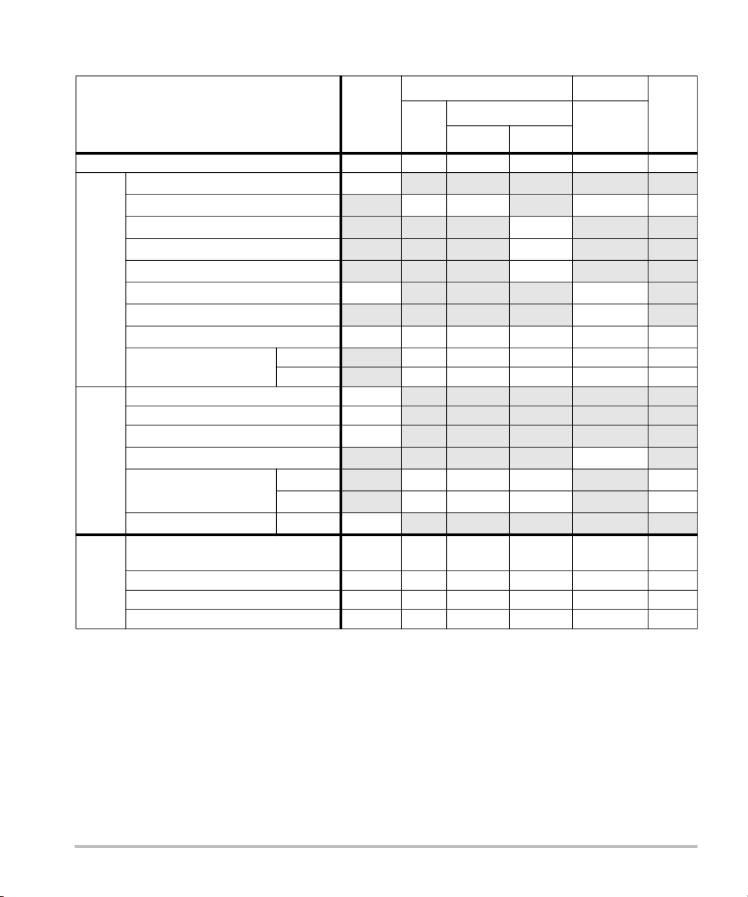
Table 7: Transducer Model: L25x Operating Mode: 2D
TIS TIB
A
aprt
Non-scan
1 A
aprt
Non-scan
TIC
>1
Index Label M.I.
Scan
Global Maximum Index Value 1.2 (a) — — — (b)
p
r.3
W
0
min of [W
z
1
z
bp
z
sp
Parameter
deq(zsp) (cm) —
Associated Acoustic
f
c
Dim of A
.3(z1
aprt
),I
TA.3(z1
)] (mW) —
(MPa) 2.87
(mW) # — — #
(cm) —
(cm) —
(cm) 0.8 —
(MHz) 6.11 # — — — #
X (cm) # — — — #
Y (cm)
# — — — #
PD (µsec) 0.630
PRF (Hz) 1061
pr@PII
max
deq@Pll
Other
Focal Length FLx (cm) # — — #
max
Information
I
@MI
PA.3
max
Control 1: Exam Type Nrv/Msk/
(MPa) 3.39
(cm) —
FL
(cm) # — — #
y
(W/cm2)
478
— — — — —
Ven/Vas
Control 2: Optimization Any — — — — —
Control 3: Depth 1.9 - 2.2 — — — — —
Control
Operating
Conditions
Control 4: MBe On — — — — —
(a) This index is not required for this operating mode; value is <1.
(b) This transducer is not intended for transcranial or neonatal cephalic uses.
# No data are reported for this operating condition since the global maximum index value is not reported
for the reason listed. (Reference Global Maximum Index Value line.)
— Data are not applicable for this transducer/mode.
10

Table 8: Transducer Model: L25x Operating Mode: PW Doppler
TIS TIB
English Deutsch Español Français Italiano Português
A
aprt
Non-scan
1 A
aprt
Non-scan
TIC
>1
Index Label M.I.
Scan
Global Maximum Index Value (a) — (a) — 1.7 (b)
p
r.3
W
0
min of [W
z
1
z
bp
z
sp
Parameter
deq(zsp) (cm) 0.30
Associated Acoustic
f
c
Dim of A
.3(z1
aprt
),I
TA.3(z1
)] (mW) —
(MPa) #
(mW) — # 32.1 #
(cm) —
(cm) —
(cm) # 0.75
(MHz) # — # — 6.00 #
X (cm) — # — 0.76 #
Y (cm)
— # — 0.30 #
PD (µsec) #
PRF (Hz) #
pr@PII
max
deq@Pll
Other
Focal Length FLx (cm) — # — #
max
Information
I
@MI
PA.3
max
Control 1: Exam Type — — — — Vas/Ven/
(MPa) #
(cm) 0.21
FL
(cm) — # — #
y
(W/cm2)
#
—
Nrv
Control 2: Sample Volume — — — — 8 mm —
Control 3: PRF — — — — 1953 —
Control
Operating
Conditions
Control 4: Sample Volume Position — — — — Zone 7 —
(a) This index is not required for this operating mode; value is <1.
(b) This transducer is not intended for transcranial or neonatal cephalic uses.
# No data are reported for this operating condition since the global maximum index value is not reported
for the reason listed. (Reference Global Maximum Index Value line.)
— Data are not applicable for this transducer/mode.
11
Nederlands

12

S-Series-Ultraschallsystem
Ergänzung zum Benutzerhandbuch P13895-06
Einführung .............................................................................................................................13
Bildgebung .............................................................................................................................14
Sicherheit ................................................................................................................................18
Einführung
Diese Ergänzung zum Benutzerhandbuch dient folgendem Zweck:
• Aktualisierung der Informationen zur Schallausgangsleistung für das
S Series™-Ultraschallsystem
English Deutsch Español Français Italiano Português
• Beschreibung der erweiterten SonoMBe
folgenden Schallköpfen verfügbar ist:
• C60x/5-2 MHz
• HFL38x/13-6 MHz
• HFL50x/15-6 MHz
• L25x/13-6 MHz
• L38xi/10-5 MHz
™ Multi-Beam-Bildgebung (MBe), die auf den
Nederlands
13

Bildgebung
2D-Bildgebung
WARNUNG:
So lässt sich eine falsche Platzierung der Nadel bei eingeschalteter MBe-Funktion
vermeiden:
• Mithilfe von Bewegungen und Flüssigkeitsinjektion Position und Wegführung der
Nadel überprüfen. MBe verbessert die Abbildung linearer Strukturen innerhalb
eines ausgewählten Winkelbereichs in der Ultraschallebene. Lineare Strukturen
außerhalb des ausgewählten Winkelbereichs oder der Ultraschallebene
beispielsweise eine gebogene Nadel – können weniger deutlich dargestellt sein.
• Bitte beachten Sie, dass lineare Strukturen nur in dem Teil des Bilds verbessert
dargestellt werden, der durch einen Umriss gekennzeichnet ist. Der Bereich
außerhalb des Umrisses bleibt unverändert (siehe Abbildung 2).
• Bitte beachten Sie, dass die Strahldivergenz bei einem Schallkopf mit gekrümmter
Anordnung dazu führen kann, dass ein Segment des Nadelschafts nicht im Bild
angezeigt wird (siehe Abbildung 3). Die Nadelspitze ist möglicherweise nicht zu
sehen.
– wie
2D-Bedienelemente
MBe Schaltet die SonoMBe-Bildgebung ein, die eine verbesserte Darstellung linearer
Strukturen innerhalb eines ausgewählten Winkelbereichs ermöglicht und die
Nadelführung bei der Positionierung von Kathetern und Nervenblockaden
vereinfacht. Der betroffene Bereich wird durch einen Umriss mit drei oder vier
Seiten gekennzeichnet (siehe Abbildung 2).
Bei Schallköpfen mit gekrümmter Anordnung kann MBe dabei helfen, die Richtung
der Nadel festzustellen, obwohl möglicherweise nur Segmente des Nadelschafts im
Bild angezeigt werden (siehe Abbildung 3). Mithilfe von Bewegung und
Flüssigkeitsinjektion kann die Position der Nadelspitze bestimmt werden.
Verwenden Sie eine 17er- bis 25er-Nadel (empfohlen). Verbesserungen an den
Ergebnissen können von der Art und der Marke der verwendeten Nadel abhängen.
Weitere Informationen über die Nadelsichtbarkeit in ultraschallgeführten Verfahren
finden Sie in der medizinischen Literatur.
Sie können die Nadel bis zu 50° von der Schallkopfoberfläche abwinkeln (siehe
Abbildung 1). Bei mehr als 50° wird die Nadel möglicherweise weniger gut dargestellt.
(MBe hat nur wenig oder keinen Nutzen bei der Nadelführung in der kurzen Achse.
MBe ist nur für die Nadelführung in der langen Achse bestimmt.)
14

Stellen Sie die Verstärkung nicht zu hoch ein, da eine unnötig hohe Verstärkung
Artefakte im Bild verursachen kann. Außerdem können Atem- und Herzbewegungen
helle pulsierende Artefakte im Bild verursachen.
Wenn MBe eingeschaltet ist, stehen zusätzliche Bedienelemente zur Verfügung:
• L/R-Drhg dreht den betroffenen Bereich (den Umriss) horizontal auf dem Bild.
Zur Neuausrichtung des gesamten Bildes die Bedienelemente zur Ausrichtung
verwenden .
• Flach, Mittel oder Steil definiert die Neigung des Umrisses, der durch eine
gepunktete Linie angezeigt wird.
• Linearer Schallkopf: Jeweils die Einstellung wählen, welche die beste senkrechte
Neigung zur gepunkteten Linie bietet. Innerhalb dieses Bereichs gilt, dass eine
lineare Struktur umso besser dargestellt wird, je senkrechter sie sich zur
gepunkteten Linie befindet. Entsprechend gilt auch, dass sie umso weniger gut
dargestellt wird, je weniger senkrecht (und stattdessen paralleler) sie sich zur
gepunkteten Linie befindet.
• Schallkopf mit gekrümmter Anordnung („curved array“): Bei einer linearen
Struktur mit einem Winkel von höchstens 30° von der Schallkopfoberfläche für
eine optimale Darstellung „Flach“ wählen. Bei einer linearen Struktur mit einem
Winkel zwischen 30-40° „Mittel“ wählen. Bei einer linearen Struktur von mehr als
40° „Steil“ wählen.
English Deutsch Español Français Italiano Português
Die Steuertaste der aktuellen Auswahl wird hervorgehoben.
• Aus schaltet MBe aus. Ein vorübergehendes Ausschalten der MBe-Funktion kann
dabei helfen, Bildfehler und andere Strukturen zu identifizieren, die nicht von
Interesse sind.
• Zurück schaltet zum vorherigen Bildschirm zurück. Wenn MBe eingeschaltet ist,
wird MBe grün hervorgehoben, und im Bereich mit Daten der Modi wird MBe
angezeigt. Durch erneutes Drücken auf MBe werden die MBe-Bedienelemente
wieder angezeigt.
Steht nur für Untersuchungen von Brust, Muskel-Skelett, Nerven und Kleinteilen sowie
in der Vollbildgebung und bei vaskulären (nur L25x) und venösen (nur L25x)
Untersuchungen zur Verfügung Wenn MBe eingeschaltet ist, steht die Option MB
nicht zur Verfügung.
Nederlands
15
0 - 50°
2
1
Abbildung 1 Zur Erzielung optimaler Ergebnisse die Nadel bis zu 50°
von der Schallkopfoberfläche abwinkeln:
1 Nadel 2 Schallkopf
1
2
3
4
Abbildung 2 Bild mit eingeschalteter MBe-Funktion (linearer Schallkopf)
1 Nadel
2 Umrissener Bereich mit MBe-Darstellung
16
3 Gepunktete Linie
4 Bereich ohne verbesserte Darstellung

1
2
Abbildung 3 Bei einem Schallkopf mit gekrümmter Anordnung werden
möglicherweise nur Segmente des Nadelschafts angezeigt:
1 Oberer Nadelschaft
2 Nadelspitze
3 Nicht angezeigtes Segment des Nadelschafts
(welches Segment bzw. welche Segmente nicht
angezeigt werden, hängt von dem jeweiligen Bild ab)
English Deutsch Español Français Italiano Português
3
17
Nederlands

Sicherheit
Ausgangsleistungsanzeige
Tabelle 1: TI oder MI 1,0
Schallkopfmodell Index
HFL38x MI Ja Ja Ja —
TIC, TIK oder
TIW
HFL50x MI Ja Ja Ja —
TIC, TIK oder
TIW
L25x MI Ja Nein Nein —
TIC, TIK oder
TIW
2D/
M Mode
Nein Ja Ja —
Nein Nein Ja —
Nein Nein Ja —
CPD/
Farbe
PW-
Doppler
CW-
Doppler
18

Schallausgangsleistung-Tabellen
Tabelle 2: Schallkopfmodell: HFL38x/13-6 Betriebsmodus: 2D
TIW TIK
English Deutsch Español Français Italiano Português
A
aprt
Non-scan
1 A
aprt
Non-scan
TIC
>1
Index-Bezeichnung MI
Scan
Globaler maximaler Indexwert 1,1 (a) — — — (b)
p
r.3
W
0
Min von [W
z
1
z
bp
z
sp
z@PII
Assoziierter
Akustikparameter
.3max
deq(zsp) (cm) —
f
c
Dim von A
.3(z1
aprt
),I
TA.3(z1
)] (mW) —
(MPa) 2,56
(mW) # — — #
(cm) —
(cm) —
(cm) —
1,2
(MHz) 5,33 # — — — #
X (cm) # — — — #
Y (cm) # — — — #
PD (µs) 0,525
PRF (Hz) 2450
pr@PII
max
deq@Pll
Fokuslänge FLx (cm) # — — #
Weitere
max
Informationen
I
@MI
PA.3
max
Regelung 1: Untersuchungstyp Nrv/Bru/
(MPa) 3,19
(cm) —
FL
(cm) # — — #
y
(W/cm2)
325,3
— — — — —
SmP/Mus
Regelung 2: Optimierung Beliebig — — — — —
Regelung 3: Tiefe 3,3 cm — — — — —
Betriebs-
regelungs-
bedingungen
Regelung 4: MBe Ein — — — — —
Nederlands
(a) Dieser Index ist für diesen Betriebsmodus nicht erforderlich. Der Wert ist <1.
(b) Dieser Schallkopf ist nicht für den transkraniellen Einsatz und für Schädeluntersuchungen bei
Neugeborenen vorgesehen.
# Für diese Betriebsbedingung liegen keine Daten vor, da aus dem angegebenen Grund kein globaler
Maximalindexwert vorliegt. (Siehe Zeile „Globaler maximaler Indexwert“.)
— Daten für diesen Schallkopf/Betriebsmodus nicht zutreffend.
19
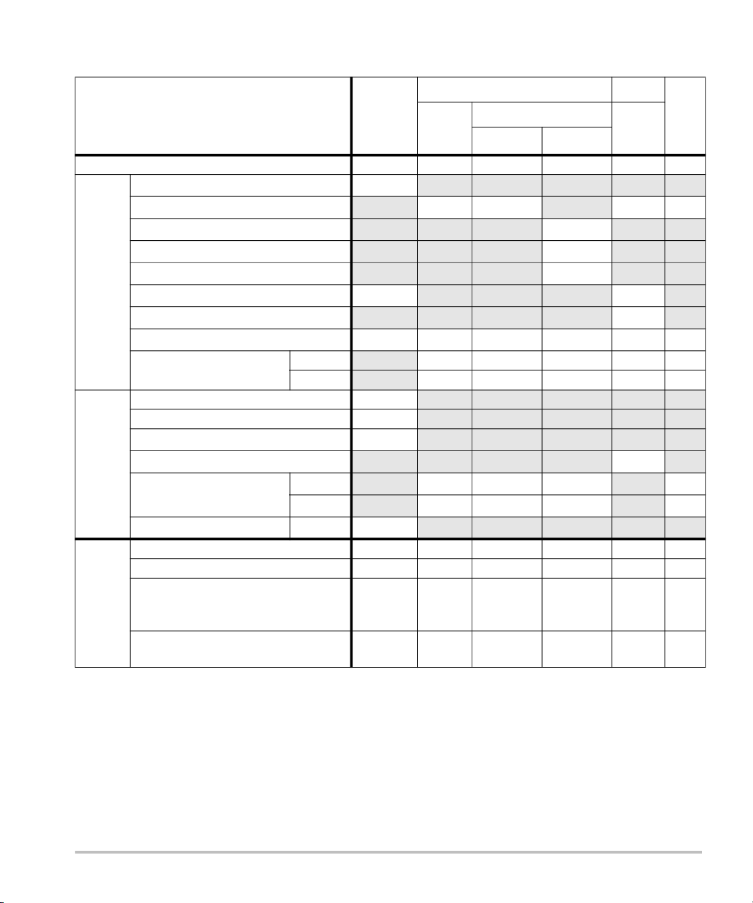
Tabelle 3: Schallkopfmodell: HFL38x Betriebsmodus: CPD/Farbe
TIW TIK
A
aprt
Non-scan
1 A
aprt
>1
Non-
scan
TIC
Index-Bezeichnung MI
Scan
Globaler maximaler Indexwert 1,1 1,0 — — — (b)
p
r.3
W
0
Min von [W
z
1
z
bp
z
sp
Assoziierter
deq(zsp) (cm) —
Akustikparameter
f
c
Dim von A
.3(z1
aprt
),I
TA.3(z1
)] (mW) —
(MPa) 2,556
(mW) 37,69 — — #
(cm) —
(cm) —
(cm) 1,2 —
(MHz) 5,328 5,324 — — — #
X (cm) 0,44 — — — #
Y (cm) 0,4 — — — #
PD (µs) 0,525
PRF (Hz) 2597
pr@PII
max
deq@Pll
Fokuslänge FLx (cm) 1,32 — — #
Weitere
max
Informationen
I
@MI
PA.3
max
(MPa) 3,187
(cm) —
FL
(cm) 2,5 — — #
y
(W/cm2)
325,5
Regelung 1: Modus Farbe Farbe — — — —
Regelung 2: Untersuchungstyp Beliebig Ven — — — —
Regelung 3: Optimierung/Tiefe/PRF Niedrig/
3,3 cm/
Betriebs-
regelungs-
bedingungen
Regelung 4: Position/Größe des
Beliebig
Beliebig Oben/
Farbbereichs
Mittel/
2,7 cm/
2841
Kurz
— — — —
— — — —
(a) Dieser Index ist für diesen Betriebsmodus nicht erforderlich. Der Wert ist <1.
(b) Dieser Schallkopf ist nicht für den transkraniellen Einsatz und für Schädeluntersuchungen bei
Neugeborenen vorgesehen.
# Für diese Betriebsbedingung liegen keine Daten vor, da aus dem angegebenen Grund kein globaler
Maximalindexwert vorliegt. (Siehe Zeile „Globaler maximaler Indexwert“.)
— Daten für diesen Schallkopf/Betriebsmodus nicht zutreffend.
20
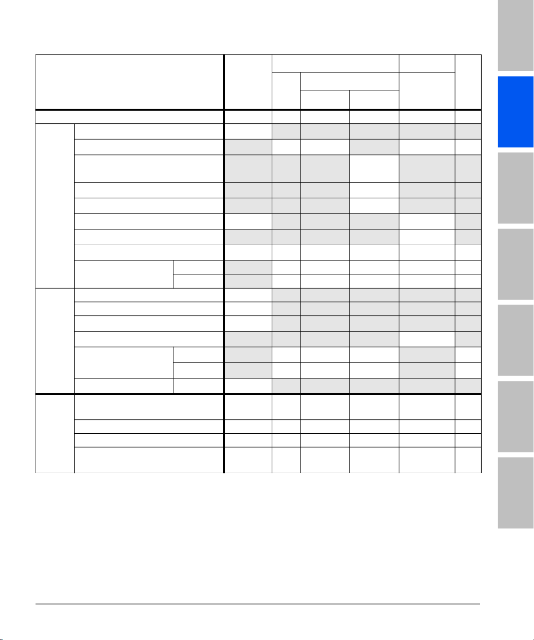
Tabelle 4: Schallkopfmodell: HFL38x Betriebsmodus: PW-Doppler
TIW TIK
English Deutsch Español Français Italiano Português
A
aprt
Non-scan
1 A
aprt
Non-scan
TIC
>1
Index-Bezeichnung MI
Scan
Globaler maximaler Indexwert 1,0 — 1,1 — 2,0 (b)
p
r.3
W
0
Min von
[W
),I
.3(z1
z
1
z
bp
z
Assoziierter
sp
deq(zsp) (cm) 0,33
Akustikparameter
f
c
Dim von A
TA.3(z1
aprt
)]
(MPa) 2,37
(mW) — 43,01 43,01 #
(mW)
—
(cm) —
(cm) —
(cm) 0,9 1,1
(MHz) 5,32 — 5,30 — 5,30 #
X (cm) — 1,04 — 1,04 #
Y (cm)
— 0,4 — 0,4 #
PD (µs) 1,29
PRF (Hz) 1008
pr@PII
max
deq@Pll
Fokuslänge FLx (cm) — 3,72 — #
Weitere
max
Informationen
I
@MI
PA.3
max
Regelung 1: Untersuchungstyp Bru/Vas/
(MPa) 2,404
(cm) 0,21
FL
(cm) — 2,5 — #
y
(W/cm2)
323,35
Beliebig Beliebig
SmP/IMT
Regelung 2: Probengröße 1 mm 1 mm 1 mm
Regelung 3: PRF 1008 6250 6250
Betriebs-
regelungs-
Regelung 4: Position der
bedingungen
Probengröße
Zone 2 Zone 7 Zone 7
Nederlands
(a) Dieser Index ist für diesen Betriebsmodus nicht erforderlich. Der Wert ist <1.
(b) Dieser Schallkopf ist nicht für den transkraniellen Einsatz und für Schädeluntersuchungen bei
Neugeborenen vorgesehen.
# Für diese Betriebsbedingung liegen keine Daten vor, da aus dem angegebenen Grund kein globaler
Maximalindexwert vorliegt. (Siehe Zeile „Globaler maximaler Indexwert“.)
— Daten für diesen Schallkopf/Betriebsmodus nicht zutreffend.
21
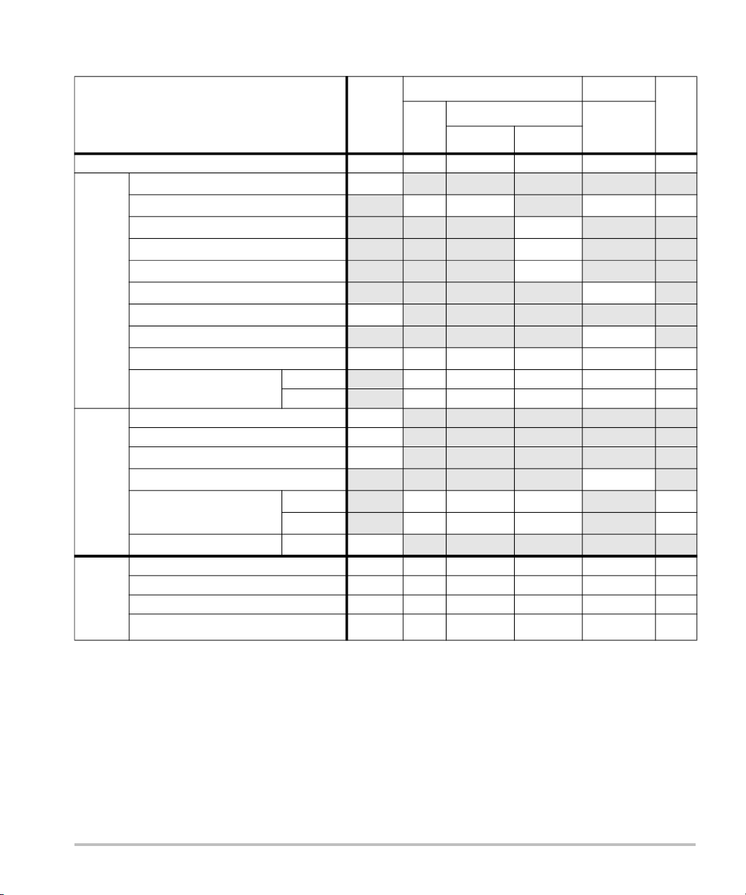
Tabelle 5: Schallkopfmodell: HFL50x Betriebsmodus: 2D
TIW TIK
A
aprt
Non-scan
1 A
aprt
Non-scan
TIC
>1
Index-Bezeichnung MI
Scan
Globaler maximaler Indexwert 1,3 (a) — — — (b)
p
r.3
W
0
Min von [W
z
1
z
bp
z
sp
z@PII
Assoziierter
Akustikparameter
.3max
deq(zsp) (cm) —
f
c
Dim von A
.3(z1
aprt
),I
TA.3(z1
)] (mW) —
(MPa) 3,051
(mW) # — — #
(cm) —
(cm) —
(cm) —
1,2
(MHz) 5,36 # — — — #
X (cm) # — — — #
Y (cm) # — — — #
PD (µs) 0,521
PRF (Hz) 2733
pr@PII
max
deq@Pll
Fokuslänge FLx (cm) # — — #
Weitere
max
Informationen
I
@MI
PA.3
max
(MPa) 3,81
(cm) —
FL
(cm) # — — #
y
(W/cm2)
493
Regelung 1: Untersuchungstyp Beliebig — — — — —
Regelung 2: Optimierung Beliebig — — — — —
Regelung 3: Tiefe 3,3 — — — — —
Betriebs-
Regelung 4: MBe Ein — — — — —
regelungs-
bedingungen
(a) Dieser Index ist für diesen Betriebsmodus nicht erforderlich. Der Wert ist <1.
(b) Dieser Schallkopf ist nicht für den transkraniellen Einsatz und für Schädeluntersuchungen bei
Neugeborenen vorgesehen.
# Für diese Betriebsbedingung liegen keine Daten vor, da aus dem angegebenen Grund kein globaler
Maximalindexwert vorliegt. (Siehe Zeile „Globaler maximaler Indexwert“.)
— Daten für diesen Schallkopf/Betriebsmodus nicht zutreffend.
22

Tabelle 6: Schallkopfmodell: HFL50x Betriebsmodus: PW-Doppler
TIW TIK
English Deutsch Español Français Italiano Português
A
aprt
Non-scan
1 A
aprt
Non-scan
TIC
>1
Index-Bezeichnung MI
Scan
Globaler maximaler Indexwert 1,2 — 1,1 — 1,9 (b)
p
r.3
W
0
Min von [W
z
1
z
bp
z
sp
Assoziierter
deq(zsp) (cm) 0,33
Akustikparameter
f
c
Dim von A
.3(z1
aprt
),I
TA.3(z1
)] (mW) —
(MPa) 2,69
(mW) — 42,6 42,6 #
(cm) —
(cm) —
(cm) 1,0 1,1
(MHz) 5,34 — 5,34 — 5,34 #
X (cm) — 1,08 — 1,08 #
Y (cm) — 0,40 — 0,40 #
PD (µs) 1,29
PRF (Hz) 1008
pr@PII
max
deq@Pll
Fokuslänge FLx (cm) — 3,72 — #
Weitere
max
Informationen
I
@MI
PA.3
max
(MPa) 3,23
(cm) 0,22
FL
(cm) — 2,44 — #
y
(W/cm2)
308
Regelung 1: Untersuchungstyp Beliebig — Beliebig — Beliebig —
Regelung 2: Probengröße 1 mm — 1 mm — 1 mm —
Regelung 3: PRF 1008 — 1563 -
Betriebs-
regelungs-
bedingungen
Regelung 4: Position der Probengröße Zone 4 — Zone 8 — Zone 8 —
3125
— 1563 -
3125
—
(a) Dieser Index ist für diesen Betriebsmodus nicht erforderlich. Der Wert ist <1.
(b) Dieser Schallkopf ist nicht für den transkraniellen Einsatz und für Schädeluntersuchungen bei
Neugeborenen vorgesehen.
# Für diese Betriebsbedingung liegen keine Daten vor, da aus dem angegebenen Grund kein globaler
Maximalindexwert vorliegt. (Siehe Zeile „Globaler maximaler Indexwert“.)
— Daten für diesen Schallkopf/Betriebsmodus nicht zutreffend.
23
Nederlands

Tabelle 7: Schallkopfmodell: L25x Betriebsmodus: 2D
TIW TIK
A
aprt
Non-scan
1 A
aprt
Non-scan
TIC
>1
Index-Bezeichnung MI
Scan
Globaler maximaler Indexwert 1,2 (a) — — — (b)
p
r.3
W
0
Min von [W
z
1
z
bp
z
sp
Assoziierter
deq(zsp) (cm) —
Akustikparameter
f
c
Dim von A
.3(z1
aprt
),I
TA.3(z1
(MPa) 2,87
(mW) # — — #
)] (mW) —
(cm) —
(cm) —
(cm) 0,8 —
(MHz) 6,11 # — — — #
X (cm) # — — — #
Y (cm)
# — — — #
PD (µs) 0,630
PRF (Hz) 1061
pr@PII
max
deq@Pll
Fokuslänge FLx (cm) # — — #
Weitere
max
Informationen
I
@MI
PA.3
max
Regelung 1: Untersuchungstyp Nrv/Mus
(MPa) 3,39
(cm) —
FL
(cm) # — — #
y
(W/cm2)
478
— — — — —
Ven/Vas
Regelung 2: Optimierung Beliebig — — — — —
Regelung 3: Tiefe 1,9 - 2,2 — — — — —
Betriebs-
regelungs-
bedingungen
Regelung 4: MBe Ein — — — — —
(a) Dieser Index ist für diesen Betriebsmodus nicht erforderlich. Der Wert ist <1.
(b) Dieser Schallkopf ist nicht für den transkraniellen Einsatz und für Schädeluntersuchungen bei
Neugeborenen vorgesehen.
# Für diese Betriebsbedingung liegen keine Daten vor, da aus dem angegebenen Grund kein globaler
Maximalindexwert vorliegt. (Siehe Zeile „Globaler maximaler Indexwert“.)
— Daten für diesen Schallkopf/Betriebsmodus nicht zutreffend.
24
 Loading...