

Page 1

USER GUIDE
Page 2

Manufacturer
FUJIFILM SonoSite, Inc.
21919 30th Drive SE
Bothell, WA 98021 USA
T: 1-888-482-9449 or 1-425-951-1200
F: 1-425-951-1201
EC Authorized Representative
FUJIFILM SonoSite B.V.
Joop Geesinkweg 140
1114 AB Amsterdam,
The Netherlands
Australia Sponsor
FUJIFILM SonoSite Australasia Pty Ltd
114 Old Pittwater Road
BROOKVALE, NSW, 2100
Australia
Caution
SonoSite SII, SonoHD2, SonoMB, SonoSite and the SONOSITE logo are registered and unregistered trademarks of FUJIFILM SonoSite, Inc.
in various jurisdictions.
DICOM is a registered trademark of the National Electrical Manufacturers Association.
FUJIFILM is a registered and unregistered trademark of FUJIFILM Corporation in various jurisdictions.
Patents: US 8,956,296; US 8,861,822; US 8,858,436; US 8,834,372; US 8,805,047; US 8,527,033; US 8,500,647;US 8,376,103; US 8,216,146; US
8,213,467; US 8,137,278; US 8,066,642; US 7,978,461; US 7,804,970; US 7,740,586; US 7,686,766; US 7,591,786; US 7,588,541; US 7,534,211;
US 7,449,640; US 7,169,108; US 6,962,566; US 6,648,826; US 6,569,101; US 6,471,651; US 6,416,475; US 6,383,139; US 6,371,918; US
6,364,839; US 6,135,961; US 5,893,363; US 5,817,024; US 5,782,769; US 5,722,412; US 8,805,047; US 8,527,033; US 8,858,436; US 8,861,822;
US 8,956,296; AU 727381; AU 730822; CA 2,371,711; CA 2,372,152; CA 2,373,065; CN103237499; CN101231457; CN 97113678.5; CN
98106133.8; CN 200830007734.8; EP 0875203; EP 0881492; EP 1175713; EP P22783-01; EP 1180971; EP 1552792; EP 1589878; JP 5782428;
JP 4696150; KR 528102; and KR 532359.
Part number: P20536-04
Publication date: November 2017
Copyright © 2017 FUJIFILM SonoSite, Inc. All rights reserved.
Federal (United States) law restricts this device to sale by or on the order of a
physician.
ii
Page 3

1. Introduction
Document conventions ...................................................................................................................................... 1-1
Getting help .............................................................................................................................................................. 1-2
2. Getting Started
About the system .................................................................................................................................................. 2-1
License Key .............................................................................................................................................................. 2-1
Preparing the system .......................................................................................................................................... 2-2
Components and connectors ................................................................................................................ 2-2
Installing or removing the battery ....................................................................................................... 2-3
Using AC power and charging the battery .................................................................................... 2-4
Turning the system on or off ................................................................................................................. 2-5
Connecting transducers ............................................................................................................................ 2-6
Inserting and removing USB storage devices .............................................................................. 2-7
System controls ...................................................................................................................................................... 2-9
Screen layout ........................................................................................................................................................... 2-9
General interaction ..............................................................................................................................................2-11
Touchpad ........................................................................................................................................................2-11
Touch screen ................................................................................................................................................2-12
Control buttons and knobs ...................................................................................................................2-12
Entering text .................................................................................................................................................2-12
Preparing transducers .......................................................................................................................................2-14
Acoustic coupling gel ...............................................................................................................................2-14
Intended uses ........................................................................................................................................................2-15
3. System Setup
Displaying the Settings pages ........................................................................................................................ 3-1
Administration setup ............................................................................................................................................ 3-2
Security settings ........................................................................................................................................... 3-2
Administering users .................................................................................................................................... 3-3
CONTENTS
Exporting and clearing the Event log ................................................................................................ 3-5
Logging in as user ................................................................................................................................................. 3-5
Choosing a secure password ................................................................................................................. 3-5
System setup ........................................................................................................................................................... 3-6
Annotations settings .................................................................................................................................. 3-6
Audio, Battery settings ............................................................................................................................. 3-7
iii
Page 4

Connectivity settings ................................................................................................................................. 3-8
Date and Time settings ............................................................................................................................. 3-9
Display Information settings .................................................................................................................3-10
Footswitch settings ...................................................................................................................................3-10
Network Status settings .........................................................................................................................3-10
OB Calculations settings .........................................................................................................................3-11
Presets settings ...........................................................................................................................................3-11
System Information settings ................................................................................................................3-12
USB Devices settings ...............................................................................................................................3-12
Limitations of JPEG format ...................................................................................................................3-13
4. Imaging
Imaging modes ....................................................................................................................................................... 4-1
2D imaging ...................................................................................................................................................... 4-1
M Mode imaging .......................................................................................................................................... 4-3
CPD and Color imaging ............................................................................................................................. 4-4
Adjusting depth and gain .................................................................................................................................. 4-5
Freezing, viewing frames, and zooming ................................................................................................... 4-6
Needle visualization ............................................................................................................................................. 4-7
About Steep Needle Profiling technology ...................................................................................... 4-7
Needle size and angle ............................................................................................................................... 4-9
Additional recommendations ...............................................................................................................4-10
Centerline .................................................................................................................................................................4-10
Imaging modes and exams available by transducer ........................................................................4-11
Annotating images ..............................................................................................................................................4-15
Patient information form ..................................................................................................................................4-16
Patient information form fields ............................................................................................................4-18
Images and clips ...................................................................................................................................................4-19
Saving images and clips .........................................................................................................................4-19
Reviewing patient exams ......................................................................................................................4-20
Printing, exporting, and deleting images and clips ..................................................................4-22
5. Measurements and Calculations
CONTENTS
Measurements ........................................................................................................................................................ 5-1
Working with calipers ................................................................................................................................ 5-1
Saving measurements ............................................................................................................................... 5-3
2D measurements ....................................................................................................................................... 5-4
M-Mode measurements .......................................................................................................................... 5-5
iv
Page 5

Calculations ............................................................................................................................................................... 5-7
Calculations menu ....................................................................................................................................... 5-7
Performing and saving measurements in calculations ............................................................. 5-8
Displaying and deleting saved measurements in calculations ............................................. 5-8
General calculations .................................................................................................................................... 5-8
Cardiac calculations ...................................................................................................................................5-10
MSK calculations ........................................................................................................................................5-15
Gynecology (Gyn) calculations ..........................................................................................................5-16
OB calculations ............................................................................................................................................5-17
Patient report .........................................................................................................................................................5-20
MSK worksheets ..................................................................................................................................................5-21
6. References
Measurement accuracy ...................................................................................................................................... 6-1
Sources of measurement errors .................................................................................................................... 6-2
Measurement publications and terminology .......................................................................................... 6-2
Cardiac references ....................................................................................................................................... 6-3
Obstetrical references ................................................................................................................................ 6-8
Gestational age tables ............................................................................................................................... 6-9
Ratio calculations ........................................................................................................................................6-12
General references ....................................................................................................................................6-12
7. Troubleshooting and Maintenance
Troubleshooting ...................................................................................................................................................... 7-1
Software licensing ................................................................................................................................................. 7-2
Maintenance ............................................................................................................................................................. 7-3
Cleaning and disinfecting ......................................................................................................................... 7-4
8. Cleaning and disinfecting
Before getting started ......................................................................................................................................... 8-1
CONTENTS
Determining the required cleaning and disinfecting level ................................................................ 8-2
Spaulding classifications ........................................................................................................................... 8-3
Clean and disinfect system and transducer to a high level (semi-critical uses) .................. 8-3
......................Clean and disinfect system and transducer to a low level (non-critical uses) 8-9
Storing the transducer ......................................................................................................................................8-12
Transporting the transducer ...........................................................................................................................8-12
v
Page 6

Cleaning the stand ..............................................................................................................................................8-14
Cleaning accessories ..........................................................................................................................................8-14
Air dry or towel dry with a clean cloth. .........................................................................................8-14
.............................................................................................................................................................................8-14
9. Safety
Ergonomic safety ................................................................................................................................................... 9-1
Position the system .................................................................................................................................... 9-2
Position yourself ........................................................................................................................................... 9-2
Take breaks, exercise, and vary activities ....................................................................................... 9-3
Electrical safety classification ........................................................................................................................... 9-4
Electrical safety ....................................................................................................................................................... 9-4
Equipment safety .................................................................................................................................................. 9-6
Battery safety .......................................................................................................................................................... 9-7
Clinical safety ........................................................................................................................................................... 9-8
Hazardous materials ............................................................................................................................................. 9-8
Electromagnetic compatibility ......................................................................................................................... 9-9
Wireless transmission ..............................................................................................................................9-10
Electrostatic discharge .............................................................................................................................9-11
Separation distance ..................................................................................................................................9-12
Compatible accessories and peripherals .......................................................................................9-12
Manufacturer’s declaration ...................................................................................................................9-14
Labeling symbols .................................................................................................................................................9-18
Specifications .........................................................................................................................................................9-22
System .............................................................................................................................................................9-22
Supported transducers ...........................................................................................................................9-23
Imaging modes ...........................................................................................................................................9-23
Images and clips storage .......................................................................................................................9-23
Accessories ...................................................................................................................................................9-24
Peripherals .....................................................................................................................................................9-24
Environmental limits .................................................................................................................................9-24
Electrical specifications ...........................................................................................................................9-25
Battery specifications ...............................................................................................................................9-25
Standards .................................................................................................................................................................9-25
CONTENTS
Electromechanical safety standards .................................................................................................9-25
EMC standards classification ................................................................................................................9-26
Biocompatibility standards ....................................................................................................................9-26
Airborne equipment standards ...........................................................................................................9-26
DICOM standard .........................................................................................................................................9-27
HIPAA standard ...........................................................................................................................................9-27
vi
Page 7

10. Acoustic Output
ALARA principle ...................................................................................................................................................10-1
Applying the ALARA principle ............................................................................................................10-1
Direct controls ..............................................................................................................................................10-2
Indirect controls ..........................................................................................................................................10-2
Receiver controls ........................................................................................................................................10-3
Acoustic artifacts ..................................................................................................................................................10-3
Guidelines for reducing MI and TI ...............................................................................................................10-3
Output display .......................................................................................................................................................10-6
MI and TI output display accuracy ....................................................................................................10-8
Factors that contribute to display uncertainty ............................................................................10-8
Related guidance documents ..............................................................................................................10-8
Transducer surface temperature rise ........................................................................................................10-9
Acoustic output measurement ..................................................................................................................10-10
In Situ, derated, and water value intensities ............................................................................10-10
Tissue models and equipment survey .........................................................................................10-11
Acoustic output tables ...................................................................................................................................10-12
Terms used in the acoustic output tables ..................................................................................10-47
Acoustic measurement precision and uncertainty ................................................................10-48
11. IT Network
Functions ..................................................................................................................................................................11-1
Network for connecting the device ...........................................................................................................11-1
Specifications for the connection ................................................................................................................11-1
Hardware specification ............................................................................................................................11-1
Software Specifications ..........................................................................................................................11-1
Security ...........................................................................................................................................................11-2
Data flow ........................................................................................................................................................11-2
A. Glossary
Terms ...........................................................................................................................................................................A-1
CONTENTS
Abbreviations ...........................................................................................................................................................A-3
Index ..................................................................................................................................... B-1
vii
Page 8

viii
Page 9

Introduction
This SonoSite SII Ultrasound System User Guide provides information on preparing and
using the SonoSite SII ultrasound system and on cleaning and disinfecting the system and
transducers. It also provides system specifications, and safety and acoustic output
information.
The user guide is for a reader familiar with ultrasound techniques. It does not provide
training in sonography or clinical practices. Before using the system, you must have
ultrasound training.
Refer to the applicable FUJIFILM SonoSite accessory user guide for information on using
accessories and peripherals. Refer to the manufacturer’s instructions for specific
information about peripherals.
Features Description
rP19x needle guide; HFL38xi
and L25x armored transducers;
Footswitch; new USB export
option
Needle guide enabled for the rP19x transducer.
HFL38xi and L25x armored transducers, and
footswitch now available. Option to disable USB
export.
Document conventions
The user guide follows these conventions:
A
WARN ING describes precautions necessary to prevent injury or loss of life.
A
Caution describes precautions necessary to protect the products.
A
Note provides supplemental information.
Numbered and lettered steps must be performed in a specific order.
Chapter 1
Bulleted lists present information in list format but do not imply a sequence.
Single-step procedures begin with
Symbols and terms used on the system and transducer are explained in “Labeling
symbols” on page 9-18 and the “Glossary” on page A-1.
Introduction 1-1
.
Page 10

Getting help
In addition to this user guide, the following resources are available:
Instructional videos available on-line.
FUJIFILM SonoSite Technical Support:
Phone
(U.S. or Canada)
Phone
(outside U.S. or
Canada)
Fax 425-951-6700
Email ffss-service@sonosite.com
Web www.sonosite.com
Europe Service Center Main: +31 20 751 2020
Asia Service Center +65 6380-5581
877-657-8118
425-951-1330, or call your local representative
English support: +44 14 6234 1151
French support: +33 1 8288 0702
German support: +49 69 8088 4030
Italian support: +39 02 9475 3655
Spanish support: +34 91 123 8451
1-2 Introduction
Page 11

Getting Started
About the system
The SonoSite SII ultrasound system is a portable, software-controlled device using
all-digital architecture. The SonoSite SII includes the following configurations:
S-Total
S-Vascular
S-Vet
The system has multiple configurations and feature sets used to acquire and display
high-resolution, real-time ultrasound images. Features available on your system depend on
system configuration, transducer, and exam type.
License Key
A license key is required to activate the software. Refer to “Software licensing” on
page 7-2. On occasion, a software upgrade may be required. FUJIFILM SonoSite provides
a USB device containing the software. One USB device can upgrade multiple systems.
Basic steps
1 Turn the system on. For power switch location, refer to Figure 2-1 on page 2-2.
2 Attach a transducer.
3 Ta p Patient, and then tap Information.
4 Complete the patient information form.
Chapter 2
Getting Started 2-1
If all imaging modes are licensed, press Mode, and select an imaging mode.
Note By default, the system is in 2D imaging.
Page 12
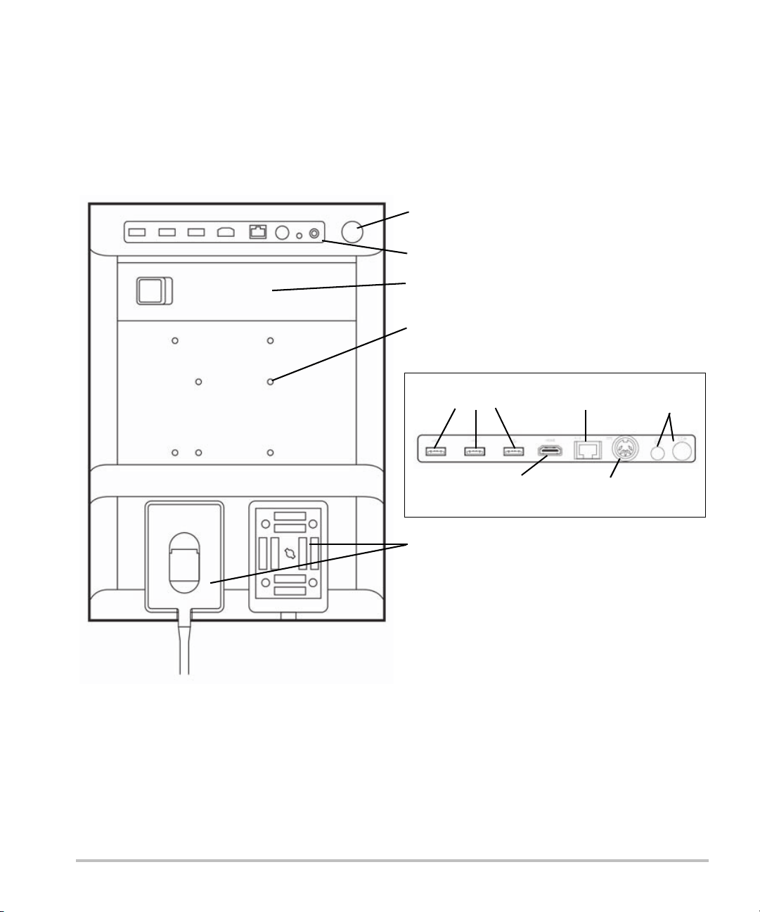
Preparing the system
Connector block (see detail below)
Battery
Transducer connector ports
USB ports
RJ45
Network port
HDMI out
DC
power in
Printer
output
Mounting holes
Power switch
Connector block detail
Components and connectors
The back of the system has compartments for the battery and two transducers as well as connectors for
USB devices, power cord, network cable, and more. Refer to Figure 2-1.
Figure 2-1 System Back
2-2 Getting Started
Page 13

Each connector has a symbol that describes its use.
USB
DC input
Composite video out
Print control
Ethernet
HDMI HDMI video out
Installing or removing the battery
WA RN I N GS To avoid injury to the operator and to prevent damage to the ultrasound system,
inspect the battery for leaks prior to installing.
To avoid data loss and to conduct a safe system shutdown, always keep a battery
in the system.
To install the battery
1 Ensure the ultrasound system is turned off.
2 Disconnect the power supply.
3 At the back of the system, slide the four prongs on the end of the battery into the slots on the right side
of the battery compartment.
Getting Started 2-3
Page 14

4 Push the battery into the battery compartment and press until the latch engages.
To remove the battery
1 Ensure the ultrasound system is turned off.
2 Disconnect the power supply.
3 Slide the locking lever on the left side of the battery, and lift the battery up.
Using AC power and charging the battery
The battery charges when the system is connected to the AC power supply. A fully discharged battery
recharges in less than five hours.
When the system is connected to AC power, the system can operate and charge the battery at the same
time.
Depending on the imaging mode and the display brightness, the system can run on battery power for up to
two hours. When running on battery power, the system may not restart if the battery charge is low. If the
system will not start due to a low battery condition, connect the system to AC power.
WA RN I N GS Verify that the hospital supply voltage corresponds to the power supply voltage
range. Refer to “Electrical specifications” on page 9-25.
Plug the system only into a grounded hospital-grade outlet.
Use only power cords provided by FUJIFILM SonoSite with the system.
2-4 Getting Started
Page 15

To operate the system using AC power
Caution Be sure to keep the battery inserted in the system even if the system is connected
to the AC power supply.
1 Connect the DC power cable from the power supply to the power connector on the system. Refer to
Figure 2-1 on page 2-2.
2 Connect the AC power cord to the power supply, and then plug it in to a hospital-grade electrical outlet.
To separate the system (and any connected equipment) from a supply mains
Cautions The equipment is not provided with an AC mains po wer switch. To disconnect the
equipment from mains, use the appliance coupler or mains plug on the power
supply cord.
Install the ultrasound system in a place where you can easily connect or
disconnect the AC power cord.
Disconnecting only the DC power cable from the system does not separate the
system from the supply mains.
Disconnect the AC power cord from the stand base.
Turning the system on or off
Caution Do not use the system if an error message appears on the display. Note the error
code and turn off the system. Call FUJIFILM SonoSite or your local representative.
To turn the system on or off
Press the power switch. Refer to Figure 2-1 on page 2-2.
To wake up the system
To conserve battery life while the system is on, the system goes into sleep mode if untouched for a preset
time. To adjust the time for sleep delay, refer to “Audio, Battery settings” on page 3-7.
Press a key, or touch the touchpad.
Getting Started 2-5
Page 16
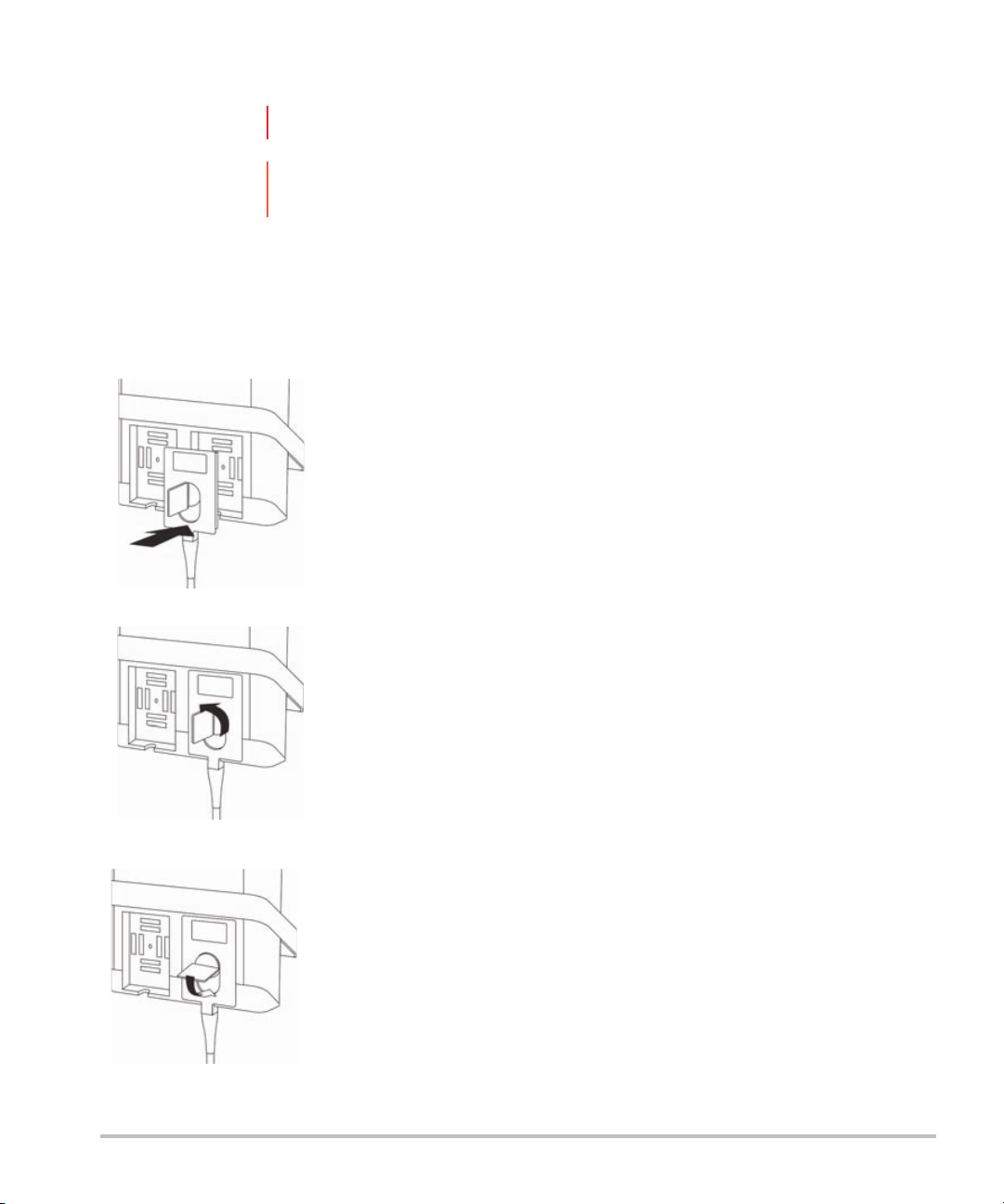
Connecting transducers
WARNIN G To avoid injury to the patient, do not place the connector on the patient.
Caution To avoid damaging the transducer connector, do not allow foreign material in the
connector.
To connect a transducer
1 Pull the transducer latch up, and rotate it clockwise.
2 Align the transducer connector with the connector on the back of the system.
3 Insert the transducer connector into one of the transducer ports on the system.
4 Turn the latch counterclockwise.
5 Press the latch down, securing the transducer connector to the system.
2-6
Page 17

To remove a transducer
1 Pull the transducer latch up, and rotate it clockwise.
2 Pull the transducer connector away from the system.
Inserting and removing USB storage devices
Images and clips are saved to internal storage and are organized in a sortable patient list. You can archive
the images and clips from the ultrasound system to a PC using a USB storage device. Although the images
and clips cannot be viewed from a USB storage device on the ultrasound system, you can remove the USB
storage device and view the images on your PC.
You can also import and export user accounts and the Event log using a USB storage device.
There are three USB ports located on the back of the system near the top. For additional USB ports, you can
connect a USB hub into any USB port.
WA RN I N GS To avoid damaging the USB storage device and losing patient data from it, observe
the following:
Do not remove the USB storage device or turn off the ultrasound system while
the system is exporting.
Do not bump or otherwise apply pressure to the USB storage device while it is
in a USB port on the ultrasound system. The connector could break.
Caution If the USB icon does not appear in the system status area on-screen, the USB
storage device may be defective or software encrypted. Turn the system off and
replace the device.
Note The system does not support password-protected or encrypted USB storage
devices. Make sure that the USB storage device you use does not have password
protection or encryption enabled.
USB storage devices must be in FAT-32 format.
Getting Started 2-7
Page 18

To insert a USB storage device
Insert the USB storage device into a USB port on the system. Refer to Figure 2-1 on page 2-2. The USB
storage device is ready when the USB icon appears.
To remove a USB storage device
Removing the USB storage device while the system is exporting may cause the exported files to be
corrupted or incomplete.
1 Wait at least five seconds after the USB animation stops.
2 Remove the USB storage device from the port.
2-8 Getting Started
Page 19
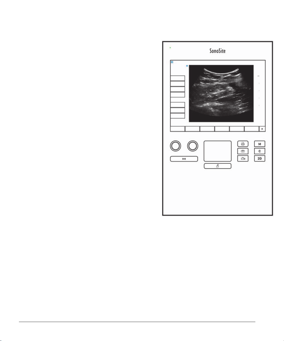
System controls
1
2
4
6
57
8
9
3
9
1 Control
knobs
2 Freeze key Press and hold to freeze or
3 Touchpad Moves the pointer and other
4Touchpad
key
5 Print key Available only when a printer is
6 Save keys Tap one of these keys to save an
7 Image mode Tap one of these keys to change
8 System
controls
Turn to adjust gain, depth, cine
buffer, brightness, and more,
depending on context. Current
functions appear on-screen above
the knobs.
unfreeze the image.
items.
Works in conjunction with the
touchpad. Tap to activate an item
on-screen, or to switch between
color box functions. (active only
when the image is frozen.)
connected to the system. Tap to
print from a live or frozen scan.
image or a clip.
the imaging mode.
Change system settings, switch
transducers, add labels, or see
patient information.
9Image
controls
Use these to adjust the image.
Figure 2-2 Control layout
Screen layout
The layout of the S onoS ite SII syste m scree n and the c ontrols that appear on it chan ge according to imaging
mode or the specific task you are performing, such as measuring or annotating. During scanning, the
following information is available:
Getting Started 2-9
Page 20
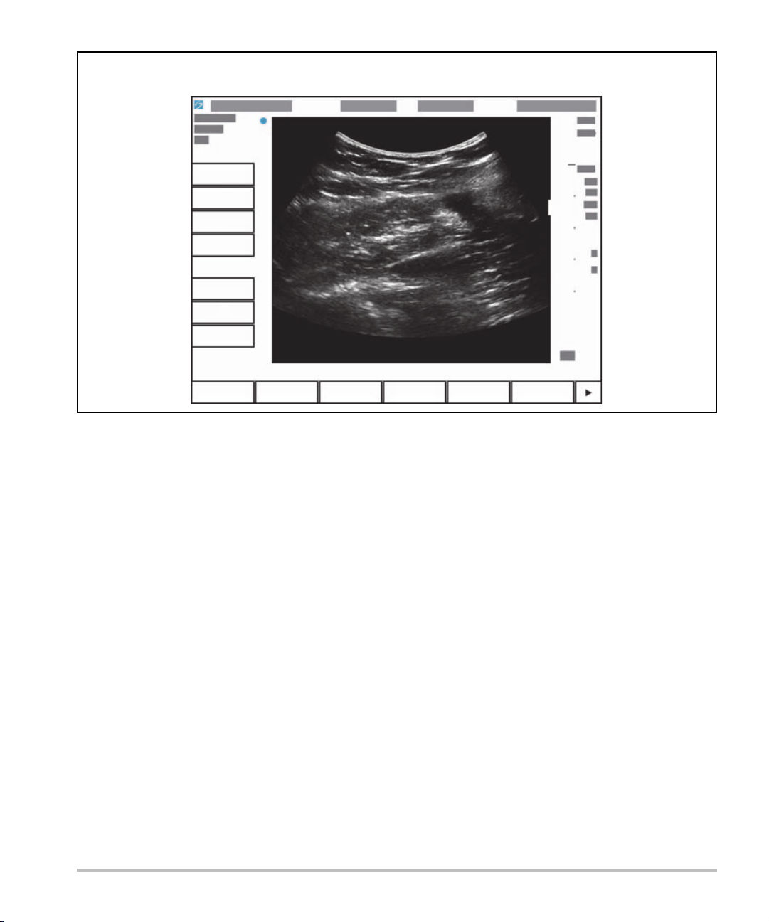
Figure 2-3 Screen layout
Patient name
Exam number
Facility
Date and time
Exam type
Transducer
Mechanical &
thermal indexes
Depth
Image status
System
controls
Image controls
2-10 Getting Started
Page 21

General interaction
Touchpad
The touchpad is an area centered below the screen that you can use as a pointing device. When the
touchpad is active, drag your finger on the surface to move the item on screen.
Figure 2-4 Using the touchpad
You can use the touchpad to do the following:
Place labels
Move calipers
Move and shape region of interest (ROI) boxes
Position the M-line
Point to a text field in a form
Use the Select key below the touchpad to select or set the item after you have moved it.
Getting Started 2-11
Page 22

Touch screen
As an alternative to the touchpad, you can move some items directly by dragging your finger on the screen.
Figure 2-5 Using the touch screen
Control buttons and knobs
There are two types of controls on the SonoSite SII system:
Screen controls
The controls that appear on the touchscreen change dynamically depending on the context. For example,
freezing an image may display the controls for zooming, performing measurements, and reviewing the
cine buffer. Only the controls that are available in the current mode or function will appear. To select a
control on the touchscreen, tap it once.
System controls
The buttons and knobs located below the touchscreen are persistent, but some may be disabled during
certain modes or conditions. Controls are lighted when active and dark when disabled. The label for each
knob appears on the screen just above it. The label and function of the knobs may change depending on
the mode or condition.
Entering text
In forms and annotations, you can enter text in text fields using either the on-screen keyboard or an external
USB keyboard connected to a USB port on the system.
2-12 Getting Started
Page 23

If you are using an external USB keyboard, enter characters by typing. The TA B key navigates among text
fields.
WARNIN G To avoid contamination, do not use the USB keyboard supplied by FUJIFILM
SonoSite in a sterile environment. The USB keyboard is not sterilized and cannot
withstand sterilization.
To enter text in text fields using the on-screen keyboard
1 Using the touchpad or the touchscreen, select a text field.
The on-screen keyboard appears with the text field at the top.
2 On the touchscreen, tap each character you want to enter.
The Äñ key displays and hides international characters.
The Symbols key displays symbols and punctuation.
The Caps Lock key turns capital letters on and off.
The Shift key turns capital letters on or off for the next letter entered.
The Delete key deletes the character right of the pointer.
The backspace key deletes the character to the left of the pointer.
3 To navigate among text fields:
Ta p Next to advance to the next field.
Ta p Prev to return to the previous field.
4 To exit the keyboard, click one of the following:
OK to save changes.
2D to save changes and display 2D imaging.
Getting Started 2-13
Page 24

Preparing transducers
WA RN I N GS Some transducer sheaths contain natural rubber latex and talc, which can cause
allergic reactions in some individuals. Refer to 21 CFR 801.437, User labeling for
devices that contain natural rubber.
Some gels and disinfectants can cause an allergic reaction in some individuals.
Cautions To avoid damage to the transducer, use only gels recommended by FUJIFILM
SonoSite. Using gels other than the one recommended by FUJIFILM SonoSite can
damage the transducer and void the warranty. If you have questions about gel
compatibility, contact FUJIFILM SonoSite or your local representative.
FUJIFILM SonoSite recommends that you clean and disinfect transducers after
each use. Refer to “Cleaning and disinfecting” on page 8-1.
Acoustic coupling gel
Acoustic coupling gel must be used during exams. Although most gels provide suitable acoustic coupling,
some gels are incompatible with some transducer materials. FUJIFILM SonoSite recommends Aquasonic
gel and provides a sample with the system.
For general use, apply a liberal amount of gel between the transducer and the body. For invasive procedures,
apply a transducer sheath.
®
WARNIN G To prevent contamination, the use of sterile transducer sheaths and sterile coupling
gel is recommended for clinical applications of an invasive nature. Do not apply the
transducer sheath and gel until you are ready to perform the procedure.
To apply a transducer sheath
To lessen the risk of contamination, install the sheath only when you are ready to perform the procedure.
1 Place gel inside the sheath.
2 Insert the transducer into the sheath.
3 Pull the sheath over the transducer and cable until the sheath is fully extended.
4 Secure the sheath using the bands supplied with the sheath.
Check for and eliminate bubbles between the face of the transducer and the sheath.
Note Bubbles between the face of the transducer and the sheath may affect the
ultrasound image.
5 Inspect the sheath to ensure that there are no holes or tears.
2-14 Getting Started
Page 25

Intended uses
The SonoSite SII ultrasound system is a general purpose ultrasound system intended for use by qualified
physicians and healthcare professionals for evaluation by ultrasound imaging or fluid flow analysis of the
human body.
The system is used with a transducer attached and is powered either by battery or by AC electrical power.
The clinician is positioned beside the patient and places the transducer onto (or into, for invasive procedures)
the patient’s body where needed to obtain the desired ultrasound image.
For the intended transducer for each exam type, refer to “Imaging modes and exams available by
transducer” on page 4-11.
The system transmits ultrasound energy into the patient’s body to obtain ultrasound images as described
below.
Abdominal imaging applications
You can assess the liver, kidneys, pancreas, spleen, gallbladder, bile ducts, transplanted organs, abdominal
vessels, and surrounding anatomical structures for the presence or absence of pathology transabdominally.
Cardiac imaging applications
You can assess the heart size and function, cardiac valves, great vessels, visualize blood flow through cardiac
valves, and assess for the presence or absence of pathology. In addition, you can identify the presence and
location of fluid around the heart and lungs used to assist in pericardiocentesis and thoracentesis procedures.
You can detect normal lung motion for the presence or absence of pathology. Gynecology and infertility
imaging applications
You can assess the uterus, ovaries, adnexa, and surrounding anatomical structures for the presence or
absence of pathology transabdominally or transvaginally.
Interventional imaging applications
You can use the system to provide ultrasound guidance for biopsy and drainage procedures, vascular line
placement, peripheral nerve blocks, amniocentesis, and other obstetrical procedures.
Obstetrical imaging applications
You can assess the fetal anatomy, viability, estimated fetal weight, gestational age, amniotic fluid, and
surrounding anatomical structures for the presence or absence of pathology transabdominally or
transvaginally. CPD and Color imaging are intended for high-risk pregnant women. High-risk pregnancy
indications include, but are not limited to, fetal hydrops, placental abnormalities, as well as maternal
hypertension, diabetes, and lupus.
Getting Started 2-15
Page 26

WA RN I N GS During the first trimester, you should limit the duration of ultrasound imaging
based on MI/TI. For more information, see “Acoustic Output” on page 10-1.
To prevent injury or misdiagnosis, do not use this system for Percutaneous
Umbilical Blood Sampling (PUBS) or in vitro Fertilization (IVF) The system has not
been validated to be proven effective for these two uses.
CPD or Color images can be used as an adjunctive method, not as a screening tool,
for the detection of structural anomalies of the fetal heart, and as an adjunctive
method, not as a screening tool, for the diagnosis of Intrauterine Growth
Retardation (IUGR)
Pediatric and neonatal imaging applications
You can assess the pediatric and neonatal abdominal, pelvic, and cardiac anatomy, pediatric hips, neonatal
head, and surrounding anatomical structures for the presence or absence of pathology.
Superficial imaging applications
You can assess the breast, thyroid, testicle, lymph nodes, hernias, musculoskeletal structures, soft tissue
structures, ophthalmic structures, and surrounding anatomical structures for the presence or absence of
pathology. You can use the system to provide ultrasound guidance for biopsy and drainage procedures,
vascular line placement, and peripheral nerve blocks.
WARNIN G To avoid injury to the patient, use only an Ophthalmic (Oph) exam type when
performing imaging through the eye. The FDA has established lower acoustic
energy limits for ophthalmic use. The system will not exceed these limits only if the
Oph exam type is selected.
Arterial and venous imaging applications
You can assess the carotid arteries, deep veins and arteries in the arms and legs, superficial veins in the arms
and legs, great vessels in the abdomen, and various small vessels feeding organs for the presence or
absence of pathology.
Contraindications
The SonoSite SII ultrasound system has no known contraindications.
2-16 Getting Started
Page 27

System Setup
Use the Settings pages to customize the system and set preferences. The Settings pages
are organized into the following categories:
Administration - Control access to the system, including user accounts and passwords.
See “Administration setup” on page 3-2
Annotations - Create and customize predefined labels. See “Annotations settings”
on page 3-6
Audio and battery - Set audio alerts and power management settings. See “Audio,
Battery settings” on page 3-7
Connectivity - Manage connections and certificates to information storage services.
See “Connectivity settings” on page 3-8
Date and time - Set the system date and time. See “Date and Time settings” on
page 3-9
Display information - Control the amount of information that appears on-screen during
imaging. See “Display Information settings” on page 3-10
Network - View the st atus of your wireless network connection. See “Network Status
settings” on page 3-10
OB calculations - Select authors for OB gestational calculations. See “OB Calculations
settings” on page 3-11
Presets - Set general preferences. See “Presets settings” on page 3-11
System information - View system hardware and software versions. See “System
Information settings” on page 3-12
USB devices - View information on all connected USB devices. See “USB Devices
settings” on page 3-12
Displaying the Settings pages
Chapter 3
To display a settings page
1 Ta p Settings.
2 Under Settings Pages, select the page you want by tapping it.
System Setup 3-1
Page 28

3 To return to imaging from a setup page, tap Done.
Administration setup
On the Administration settings page, you can configure the system to require users to log in and enter
passwords. Required login helps protect patient data. You can also add and delete users, change passwords,
import and export user accounts, disable USB export, and display the Event log.
To log in as Administrator
1 On the Administration settings page, type Administrator in the Name box. Refer to “Entering
text” on page 2-12.
Note The entries for Name and Password are case-sensitive.
2 Type the administrator password in the Password box.
If you don’t have the administrator password, contact FUJIFILM SonoSite. Refer to “Getting help” on
page 1-2.
WA RN I N G Restoring an administrative password will result in the deletion of data. Back up all
data prior to resetting the administrative password.
3 Ta p Login.
To log out as Administrator
Turn off or restart the system.
Security settings
WARNING Health care providers who maintain or transmit health information are required
by the Health Insurance Portability and Accountability Act (HIPAA) of 1996 and
the European Union Data Protection Directive (95/46/EC) to implement
appropriate procedures: to ensure the integrity and confidentiality of
information; to protect against any reasonably anticipated threats or hazards to
the security or integrity of the information or unauthorized uses or disclosures of
the information.
Security settings on the system allow you to meet the applicable security requirements listed in the HIPAA
standard. Users are ultimately responsible for ensuring the security and protection of all electronic protected
health information collected, stored, reviewed, and transmitted on the system.
3-2 System Setup
Page 29

To require user login
You can set the system to display the User Login screen at startup.
1 Log in as Administrator.
2 In the User Login list, tap On.
On requires a user name and password at startup.
Off allows access to the system without a user name and password.
To change the administrator password or let users change passwords
1 Log in as Administrator.
2 Under User List, tap Administrator.
3 To change the administrator password:
a Under User Information, in the Password box, type the new password.
b In the Confirm box, type the new password again. For more information about passwords, see
“Choosing a secure password” on page 3-5.
4 To let users change their passwords, select the Password changes check box.
5 Ta p Save.
To limit USB export of exam data
1 Log in as Administrator.
2 Select Disable USB Export.
Administering users
These settings enable you to manage user information directly.
To add a new user
1 Log in as Administrator.
2 Ta p New.
3 Under User Information, fill in the Name, Password, and Confirm boxes. For more information about
passwords, see “Choosing a secure password” on page 3-5.
(Optional) In the User box, type the user’s initials to display them in the patient header and the User
box in the patient information form.
(Optional) Select the Administration Access check box to allow access to all administration
privileges.
System Setup 3-3
Page 30

4 Ta p Save.
To modify user information
1 Log in as Administrator.
2 Under User List, tap the user.
3 Under User Information, make changes as desired.
4 Ta p Save. Any change to the user name replaces the previous name.
To delete a user
1 Log in as Administrator.
2 Under User List, tap the user.
3 Ta p Delete.
4 Ta p Ye s.
To change a user password
1 Log in as Administrator.
2 Under User List, tap the user.
3 Type the new password in the Password box and Confirm box.
4 Ta p Save.
Exporting or importing user accounts
The export and import commands let you configure multiple systems and back up user account information.
To export user accounts
1 Insert a USB storage device. For more information, see “Inserting and removing USB storage devices”
on page 2-7.
2 Log in as Administrator.
3 Ta p Export. A list of USB devices appears.
4 Tap the USB storage device, and then tap Export.
All user names and passwords are copied to the USB storage device. Passwords are encrypted.
To import user accounts
1 Insert the USB storage device that contains the accounts. For more information, see “Inserting and
removing USB storage devices” on page 2-7.
3-4 System Setup
Page 31

2 Log in as Administrator.
3 Ta p Import.
4 Tap the USB storage device, and then tap Import.
5 Ta p Restart in the dialog box that appears. The system restarts.
All user names and passwords on the system are replaced with the imported data.
Exporting and clearing the Event log
The Event log collects errors and events and can be exported to a USB storage device and read on a PC.
Logging in as user
If user login is required, the User Login screen appears when you turn on the system. For more information,
see “To require user login” on page 3-3.
To log in as user
1 Turn on the system.
2 In the User Login screen, type your name and password, and tap OK.
To log in as guest
Guests can scan but can’t access system setup and patient information.
1 Turn on the system.
2 In the User Login screen, tap Guest.
To change your password
1 Turn on the system.
2 In the User Login screen, tap Password.
3 Type your old and new passwords, confirm the new password, and then tap OK.
Choosing a secure password
To ensure security, choose a password that contains uppercase characters (A-Z), lowercase characters (a-z),
and numbers (0-9). Passwords are case-sensitive.
System Setup 3-5
Page 32

System setup
Annotations settings
On the Annotations settings page, you can customize predefined labels and set the preference for
managing text when unfreezing images.
For instructions to annotate images, refer to “Annotating images” on page 4-15.
To predefine a label group
You can specify which labels are available for an exam type when annotating an image. Refer to “To place
text on an image” on page 4-15.
1 On the Annotations settings page, in the Exam list, select the exam type that includes the labels you
want to specify.
2 Choose the label group associated with that exam. Next to Group, select A, B, or C. The preset labels for
the selected group appear in the scroll list.
3 To add a custom label to the group:
a Tap <New> in the scroll list.
b Type the label in the Tex t box.
c Ta p Add.
4 To rename a lab el:
a Tap the label
b Type the new name in the Tex t box
c Ta p Rename.
5 To move a label within the group:
a Tap the label
b Tap the up or down arrow.
6 To delete a label from a group, tap the label, and then tap Delete.
Refer to also “Entering text” on page 2-12.
3-6 System Setup
Page 33

To specify text retention when unfreezing
You can specify which text to keep when you unfreeze an image or change the imaging layout.
In the Unfreeze list on the Annotations settings page, select Keep All Text, Keep Home Text, or Clear
All Text.
Note The default setting is Keep All Text. For information on setting the home position,
refer to “To place an arrow on an image” on page 4-15.
To export predefined label groups
1 Insert a USB storage device.
2 On the Annotations settings page, tap Export. A list of USB devices appears.
3 Select the USB storage device, and then tap Export.
A copy of all predefined label groups for all exams saves to the USB storage device.
To import predefined label groups
1 Insert the USB storage device that contains the label groups.
2 On the Annotations settings page, tap Import.
3 Select the USB storage device, and then tap Import.
4 Ta p OK in the dialog box that appears.
All predefined label groups for all exams are replaced with those from the USB storage device.
Audio, Battery settings
On the Audio, Battery settings page, you can select options from the following lists:
Key click
Controls whether the controls make a clicking sound when tapped.
Choose either On or Off.
Beep alert
Controls whether the system beeps when saving, warning, starting, or shutting down.
Choose either On or Off.
Sleep delay
System Setup 3-7
Page 34

Specifies the period of inactivity before the system goes into sleep mode. Set to either five minutes, ten
minutes, or Off. Turning off the sleep delay prevents the system from going into sleep mode.
Choose either Off, 5, or 10.
Power delay
Specifies the period of inactivity before the system automatically turns off. Set to either 15 minutes, 30
minutes, or Off. Turning off the power delay prevents the system from turning itself off.
Choose either Off, 15, or 30.
Connectivity settings
On the Connectivity settings page, select options for using devices and for alerts when internal storage is
full. You also import wireless certificates and specify settings (including Transfer Mode and Location) for
PDAS™ Image Manager and DICOM
documentation.
To configure the system for a printer
1 Set up the printer hardware. Refer to instructions included with the printer or stand.
2 On the Connectivity settings page, choose a printer from the Printer menu.
®
, which are optional features. Refer to the PDAS and DICOM
3 Plug the printer cable into the video output on the system.
To configure the system for a DVD recorder
1 On the Connectivity settings page, in the Video Mode list, choose the video standard: NTSC or PA L.
2 Restart the system.
3 Plug the DVD recorder cable into the video output on the system.
To connect to PDAS
1 On the Connectivity settings page, choose PDAS from the Transfer mode list.
2 Restart the system.
3 On the Connectivity settings page, tap PDAS setup.
4 On the PDAS page, choose the PDAS account you want to use, and then tap Save.
5 To create a new account:
a Tap New.
3-8 System Setup
Page 35

b Enter the network settings for your new PDAS account. Work with your network administrator to obtain
the correct information.
c Ta p Save.
6 To import the PDAS connection information:
a Insert the USB storage device that contains the PDAS connection information.
b On the PDAS page, tap Import.
c Choose the USB storage device, and then tap Import.
7 To export your PDAS connection information:
a Insert a USB storage device.
b On the PDAS page, tap Export.
c Choose the USB storage device, and then tap Export.
8 Ta p Done.
To connect to DICOM
1 On the Connectivity settings page, choose DICOM from the Transfer mode list.
2 Restart the system.
3 On the Connectivity settings page, tap DICOM setup.
4 On the DICOM page, choose a location, and then choose the DICOM server you want to connect to.
5 Ta p Verify and check that communication with the DICOM server is successful.
6 Ta p Done.
To receive storage alerts
On the Connectivity settings page, select Internal Storage Capacity Alert. The system displays a
message if internal storage is near capacity when you end an exam.
Date and Time settings
To set the date and time
1 On the Date and Time settings page, do the following:
a In the Date box, type the current date. Refer to “Entering text” on page 2-12.
b In the Time box, type the current time in 24 hour format (hours and minutes).
System Setup 3-9
Page 36

Display Information settings
On the Display Information settings page, you can specify which details appear on-screen during imaging.
For example, you can help protect patient privacy by not displaying the patient name and ID on the screen.
You can select check boxes in the following sections:
Patient Header
Information from the patient information form. Refer to “Patient information form” on page 4-16.
Mode Data
Imaging information.
System Status
Power, battery, connectivity, and similar information.
Footswitch settings
On the Footswitch setup page, you can program the footswitch to perform common tasks.
Footswitch (L), Footswitch (R). Set the left and right footswitches to: Save Clip, Freeze, Save Image,
or Print.
To connect the footswitch
The FUJIFILM SonoSite footswitch allows hands-free operation with a customizable two-pedal footswitch.
The footswitch is an optional feature.
WA RN I N G To avoid contamination, do not use the footswitch in a sterile environment. The
footswitch is not sterilized.
1 Connect the footswitch USB cable to a USB port on the back of the ultrasound system.
2 On the Footswitch setup page, select a function for the left and right footswitches.
Network Status settings
The Network Status settings page displays information on system IP address, Location, Ethernet MAC
address, and the wireless connection if any.
3-10 System Setup
Page 37

OB Calculations settings
On the OB Calculations settings page, you can select authors for OB gestational calculation tables. Refer
to also “OB calculations” on page 5-17.
To specify gestational age
On the OB Calculations settings page, select the desired OB authors (or select None) in the
measurement lists under Gestational Age. Selecting an author places the associated measurement on
the calculations menu.
Presets settings
The Presets settings page enables you to choose some general preferences. Use the following information
to help you choose the presets that are right for you:
Depth Markers
Type 1
Displays an unnumbered depth scale to the right of the image, with the maximum depth number in the
lower right screen.
Type 2
Displays a numbered depth scale to the right of the image.
Thermal Index
Choose between TIS, TIB, or TIC.
By default, this setting is based on exam type: OB is TIB, and all others are TIS.
Clip Length
Choose the maximum clip length. Clip lengths are in seconds.
Units
Choose the units you want to use for patient height and weight in cardiac exams: in/ft/lbs or cm/m/kg.
Language
You can change the language used in the system interface. Changing the language requires restarting the
system.
Auto save Pat. Form
System Setup 3-11
Page 38

When turned on, automatically saves the patient information form as an image in the patient’s file.
Save Key:
Determines the behavior of the Save key:
Image Only
Saves the image to internal storage.
Image/Calcs
Saves the image to internal storage and saves the current calculation to the patient report.
Duplex
Specifies the screen layout when displaying M Mode trace:
1/3 2D, 2/3 Trace
Divides the screen so that the top 1/3 shows the 2D image, while the bottom 2/3 displays the trace.
1/2 2D, 1/2 Trace
The 2D image and the trace each occupy 1/2 of the screen.
Full 2D, Full Trace
You can switch between the two full-screen views.
System Information settings
The System Information settings page displays system hardware and software versions, patents, and
license information.
To enter a license key, see “To enter a license key” on page 7-3.
To display patents
On the System Information settings page, tap Patents.
USB Devices settings
On the USB Devices settings page, you can view information about connected USB devices, including
space availability. You can also specify a file format for images in patient exams that you export to a USB
storage device.
To help secure sensitive patient information, the USB export feature can be disabled by the administrator.
For more information about disabling USB export, see “To limit USB export of exam data” on page 3-3
3-12 System Setup
Page 39

To specify a file format for exported images
The image format you specify affects only still images. Clips export in H.264 video format saved as MP4 files.
To export images
1 On the USB Devices setup page, tap Export.
2 Under PDAS, select an image format. For JPEG image format, also select a JPEG compression.
Note A high compression has a smaller file size but less detail.
3 Select a sort order under Sort By. The sort order specifies how exported files are organized.
4 To return to the previous screen, click Devices.
To include private tags
1 If you use DICOM export type and a FUJIFILM SonoSite software product, include private tags on the
images.
2 On the USB Devices setup page, select Include private tags.
Note Because the tags may be incompatible with some earlier archivers, keep this check
box unselected unless you use FUJIFILM SonoSite software products. For more
information, refer to the ultrasound system’s DICOM conformance statement.
Limitations of JPEG format
When transferring or exporting images in JPEG format, the system uses lossy compression. Lossy
compression may create images that have less absolute detail than BMP format and that don’t render
identically to the original images.
JPEG settings:
Setting Quality Level
Low 100%; Difference image between compressed and
uncompressed is near 0
Medium 90%; Generally loss only to high frequency content (edges)
High 75%; General loss of detail
System Setup 3-13
Page 40

In some circumstances, lossy-compressed images may be inappropriate for clinical use. For example, if you
®
use images in SonoCalc
IMT software, you should transfer or export them using BMP format. SonoCalc IMT
software uses a sophisticated algorithm to measure images, and lossy-compression may cause errors.
For more information on using lossy-compressed images, consult the industry literature, including the
following references:
“Physics in Medicine and Biology, Quality Assessment of DSA, Ultrasound and CT Digital Images
Compressed with the JPEG Protocol,” D Okkalides et al. 1994 Phys Med Biol 39 1407-1421 doi:
10.1088/0031-9155/39/9/008 www.iop.org/EJ/abstract/0031-9155/39/9/008
“Canadian Association of Radiologists, CAR Standards for Irreversible Compression in Digital Diagnostic
Imaging within Radiology,” Approved: June 2008. www.car.ca/Files/%5CLossy_Compression.pdf
3-14 System Setup
Page 41

Imaging
Imaging modes
The SonoSite SII system has a high-performance liquid crystal display (LCD) and advanced
image-optimization technology that simplifies user controls. Available imaging modes
depend on the transducer and exam type. Refer to “Imaging modes and exams
available by transducer” on page 4-11.
2D imaging
2D is the system's default imaging mode. The system displays echoes in two dimensions
by assigning a brightness level based on the echo signal amplitude. To achieve the best
image quality, properly adjust the gain and depth settings, viewing angle, and exam type.
For more information about presets, see “Presets settings” on page 3-11.
To display the 2D image
1 Do one of the following:
Turn on the system.
From another imaging mode, tap 2D.
2 Adjust controls. For more information, see “2D controls.”
2D controls
Note If the control you want does not appear on the screen, tap the
More Controls arrow to view additional controls.
Chapter 4
Imaging 4-1
Page 42

Refer to also “Adjusting depth and gain” on page 4-5.
Table 4-1: 2D controls
Control Description
Gain Adjusts the image brightness through signal amplification. To change the gain, rotate
the Gain knob.
Depth Adjusts the depth of the image. To change the depth, rotate the Depth knob.
Auto Gain The gain adjusts automatically each time you press the key.
To adjust gain manually, see “Adjusting depth and gain” on page 4-5.
Optimize Settings are as follows:
Res provides the best possible resolution.
Gen provides a balance between resolution and penetration.
Pen provides the best possible penetration.
Some of the parameters optimized to provide the best image include focal zones,
aperture size, frequency (center and bandwidth), and waveform. They cannot be
adjusted by the user.
THI Turns Tissue Harmonic Imaging on and off.
When on, THI appears in the mode data area. This feature depends on transducer and
exam type.
SonoMB
Turns SonoMB® multi-beam imaging on and off. When on, MB appears in the mode
data area. This feature depends on transducer and exam type.
Orientation Select from four image orientations: U/R (Up/Right), U/L (Up/Left), D/L (Down/Left),
D/R (Down/Right).
Guide Turns needle guidelines on. Guidelines can be used for needle guidance, and depend
on transducer type.
If using a variable angle needle guide, tap Guide. To select the angle, tap A, B, or C. To
change the depth, move your finger on the touchscreen or the touchpad. To turn
needle guidelines off, tap A, B, or C until the word Guide appears..
Dual Displays side-by-side 2D images.
Ta p Dual, and then tap Update to display the second screen and to toggle between
the screens.
To return to full-screen 2D imaging, tap Off.
Monitor
Adjusts the screen brightness. Tap the button to show more controls, and then turn
the Monitor knob. The default brightness value is 8, but settings range from 1 to 10.
The screen brightness affects battery life. To conserve battery life, adjust brightness to
a lower setting.
4-2 Imaging
Page 43

M Mode imaging
Motion mode (M Mode) is an extension of 2D. It provides a trace of the 2D image displayed over time. A
single beam of ultrasound is transmitted, and reflected signals are displayed as dots of varying intensities,
which create lines across the screen.
To display the M-line
1 Ta p M.
Note If the M-line does not appear, make sure that the image isn’t frozen.
2 Drag your finger on either the touchpad or the touchscreen to position the M-line where desired.
3 Adjust controls as desired.
4 Ta p M to start the M Mode trace.
M Mode controls
Table 4-2: M Mode controls
Control Description
Gain Adjusts the signal amplification. To change the gain, rotate the Gain knob.
Depth Adjusts the depth of the scan. To change the depth, rotate the Depth knob.
M line
position
Scan speed Controls the speed of the trace. Your options are Fast, Med, and Slow.
To display the M Mode trace
1 Display the M line.
2 Adjust the depth if necessary to show the structure you want to scan. For more information, see
“Adjusting depth and gain” on page 4-5.
3 Using the touchpad or the touchscreen, move the M line to pass through the structures you want to scan.
4 To begin the trace, tap M.
A trace window appears. For information about changing the duplex layout, see “Presets settings” on
page 3-11.
Note The time scale above the trace has small marks at 200 ms intervals and large
Defines the area of interest so that movement can then be traced over time. To change
the position of the M line, drag your finger on the touchpad or the touchscreen.
marks at one-second intervals.
Imaging 4-3
Page 44

5 To change the sweep speed, tap Slow, Med, or Fast to cycle through each sweep speed.When the trace
is frozen, you can change between the M-line and M-mode trace by tapping Update M or Update 2D.
CPD and Color imaging
Color power Doppler (CPD) is used to visualize the presence of detectable blood flow. Color is used to
visualize the presence, velocity, and direction of blood flow in a wide range of flow states.
To display the CPD or Color image
1 Ta p C to enter Color mode.
A ROI box appears in the center of the 2D image. The current selection (Color or CPD) appears in the
mode data area.
Note In Color imaging, the Color indicator bar on the upper left-hand screen displays
velocity in cm/s.
2 To change to CPD, tap CPD.
3 Using the touchpad or the touchscreen, you can change the position or size of the ROI box as needed.
Ta pp in g Position or Size, or tapping , switches between position and size. When resizing, the outline
is a dashed line.
4 Adjust controls as desired. Refer to “CPD and Color controls.”
CPD and Color controls
Table 4-3: CPD and Color controls
Control Description
Flow
Sensitivity
PRF Scale Select the desired PRF (pulse repetition frequency) Scale setting by tapping PRF, and
Invert Switches the displayed direction of flow.
4-4 Imaging
Choose one of the following:
Flow Low optimizes the system for low flow states.
Flow Med optimizes the system for medium flow states.
Flow High optimizes the system for high flow states.
then tapping either the up or down arrow.
The available PRF Scale settings depend on the Flow Sensitivity setting.
Available on select transducers.
Available in Color imaging.
Page 45

Table 4-3: CPD and Color controls
Control Description
Steering If using a linear array transducer, tap the Steering button to change the steering angle
(for example: -15, 0, or +15).
Wall Filter A high wall filter can reduce excessive motion or noise, while a low wall filter displays
more of the raw signal.
Choose one of the following:
WF Low
WF Med
WF High
Varian ce (Cardiac exam only) Turns variance on and off.
Adjusting depth and gain
To adjust depth
You can adjust the depth in all imaging modes except M Mode. The vertical depth scale is marked in 0.5 cm,
1 cm, and 5 cm increments, depending on the depth.
Turn the Depth knob:
Clockwise
Increases the displayed depth.
Counter-clockwise
Decreases the displayed depth.
To change the style of depth markers, see “Presets settings” on page 3-11.
To adjust gain automatically
To adjust gain automatically in 2D, you can tap the Auto Gain button. For more information, see “2D
controls” on page 4-1.
To adjust gain manually
Gain adjusts the overall gain applied to the entire image. In CPD or Color imaging, the Gain knob affects the
color gain applied to the region of interest (ROI) box.
1 Turn the Gain knob:
Imaging 4-5
Page 46

Clockwise
Raises the gain.
Counter-clockwise
Lowers the gain.
2 To switch to near or far gain, tap the Gain button, or press the Gain knob.
Freezing, viewing frames, and zooming
To freeze or unfreeze an image
Press and hold the Freeze button ( ).
When the image is frozen, the button color is blue. When the image is unfrozen, the button color is white.
On a frozen image, the cine icon ( ) and frame number appear above the left knob.
To move forward or backward in the cine buffer
On a frozen image, do one of the following:
Turn the Cine knob.
Drag your finger on the touchscreen.
Drag your finger on the touchpad.
The total number of frames appears next to the cine icon. The number changes to the current frame
number as you move forward or backward.
WARNIN G
To zoom in on an image
You can zoom in 2D or Color imaging. You can freeze or unfreeze the image or change the imaging mode
at any time while zooming.
1 Ta p Zoom. A ROI box appears.
2 Using the touchpad or the touchscreen, position the ROI box as desired.
3 Ta p Zoom. The image in the ROI box is magnified by 100%.
4 (Optional) If the image is frozen, use the touchpad or the touchscreen to pan the image up, down, left,
and right.
5 To exit zoom, tap Zoom Off.
4-6 Imaging
To avoid loss of data, be careful not to touch the Freeze button ( ) while turning
the Cine knob.
Page 47

Needle visualization
WA RN I N GS To avoid incorrect needle placement when Steep Needle Profiling (SNP) is on:
Use only FUJIFILM SonoSite or CIVCO approved needle guides, brackets,
supplies, components, and accessories. Other brands may not properly fit
FUJIFILM SonoSite transducers.
Use only needle guides compatible with the transducers listed in Ta b le 4- 4 ,
“Transducers and exam types available with SNP” on page 4-7.
Using movement and fluid injection, verify the needle-tip location and trajectory.
Steep Needle Profiling technology enhances linear structures within a selected
angle range on the ultrasound plane. Linear structures outside the selected angle
range or the ultrasound plane
Note that linear structures are enhanced only in an outlined portion of the image.
The area outside the outline remains unchanged.
Note that the beam divergence of a curved array transducer may prevent a
segment of the needle shaft from showing in the image. The needle tip may not
show.
About Steep Needle Profiling technology
The SNP control turns on Steep Needle Profiling technology (formerly SonoMBe™ imaging), which enhances
linear structures within a selected angle range and can facilitate needle guidance during catheter placement
and nerve-block procedures. A three- or four-sided outline indicates the enhancement area as shown in
Figure 4-1 on page 4-8.
—such as a bent needle—may be less apparent.
For curved array transducers, Steep Needle Profiling technology can help identify the direction of the needle,
although only segments of the needle shaft may show in the image. See Figure 4-2 on page 4-8. Use
movement and fluid injection to help verify the needle-tip location.
The SNP control is available in 2D full-screen imaging only and on the following:
Table 4-4: Transducers and exam types available with SNP
Transducer Arterial Breast Musculoskeletal Nerve
C35x
rC60xi
standard/
armored
Imaging 4-7
Small
Parts
Ven ous Spine
Page 48

Table 4-4: Transducers and exam types available with SNP
Needle shaft
Outlined area
enhanced by SNP
Dotted line
Unenhanced area
Upper needle shaft
Segment of needle
shaft not shown
(depends on
specific image)
Needle tip
Transducer Arterial Breast Musculoskeletal Nerve
HFL38xi
standard/
armored
HFL50x
HSL25x
L25x
standard/
armored
L38xi
standard/
armored
Small
Parts
Ven ous Spine
Figure 4-1 Image with SNP on (linear transducer)
Figure 4-2 When using a curved-array transducer, only segments of the needle shaft may appear.
4-8 Imaging
Page 49

Needle size and angle
Needle
Transducer
Use a 17-gauge to 25-gauge needle (recommended). Enhancement results can depend on the type and
brand of needle used. For more information, consult the medical literature on needle visibility in
ultrasound-guided procedures.
You can angle the needle up to 50° from the transducer surface as shown in Figure 4-3 on page 4-9.
Beyond 50°, the needle may be less enhanced.
WARNIN G To avoid patient injury when using a multi-angle bracket, make sure that the same
angle is selected (A, B, or C) on both the bracket and the ultrasound system.
Note Steep Needle Profiling technology is intended for in-plane procedures only. Steep
Needle Profiling technology has little or no benefit to out-of-plane procedures.
Figure 4-3 For best results, angle the needle only up to 50° from the transducer surface.
SNP subcontrols
When Steep Needle Profiling technology is on, additional controls are available:
L/R Flip flips the affected area (the outline) horizontally on the image. For reorienting the entire image,
use the orientation control. See “2D controls” on page 4-1.
Shallow, Medium, or Steep sets the outline’s sloped edge, which is indicated by a dotted line. The
current selection is highlighted.
Linear transducer:
line. Within the enhancement area, the more perpendicular that a linear structure is to the dotted line,
the more it is enhanced. Similarly, the less perpendicular (and more parallel) that a linear structure is to
the dotted line, the less it is enhanced.
Curved array transducer:
Shallow for best enhancement. For a linear structure angled 30-40°, use Medium. For a linear
structure angled 40° or greater, use Steep.
Imaging 4-9
Use whichever setting best provides a perpendicular intersection with the dotted
For a linear structure angled 30° or less from the transducer surface, use
Page 50

Off turns off SNP. Temporarily turning off SNP can help you identify artifacts and other structures not of
Ensure orientation
marks on the screen
and transducer are
on the same side
Scan plane
Centerline
Anatomical
feature
interest.
Note If Steep Needle Profiling technology is on, the MB control is unavailable.
Additional recommendations
Avoid setting the gain too high when using Steep Needle Profiling technology, as unnecessarily high gain
can cause artifacts in the image. Also, respiratory and cardiac movement in the image may cause bright
pulsating artifacts.
Centerline
The centerline graphic aligns with the center mark of the transducer and serves as a reference mark for the
center of the displayed image.
When using the Centerline feature as a reference during a freehand procedure, be aware that the centerline
represents only the center of the ultrasound image and is not an accurate predictor of the path the needle
will take.
Figure 4-4 Relationship of the centerline graphic to the transducer and the ultrasound image.
Small tilts or rotations of the transducer can affect the relationship between any external reference points
and the anatomy that appears on the ultrasound image.
4-10 Imaging
Page 51

Figure 4-5 Relationship of the ultrasound image to the transducer angle or tilt.
Imaging modes and exams available by transducer
WA RN I N GS To prevent misdiagnosis or harm to the patient, understand your system’s
capabilities prior to use. The diagnostic capability differs for each transducer,
exam type, and imaging mode. Transducers are developed to specific criteria
depending on their physical application. These criteria include
biocompatability requirements. Understand the system’s capabilities before
using.
To avoid injury to the patient, use only an Oph t h almic (Oph ) e xam type whe n
performing imaging through the eye. The FDA has established lower acoustic
energy limits for ophthalmic use. Only the Oph exam type is designed to not
exceed these limits.
The transducer you use determines which exam types are available. In addition, the exam type you select
determines which imaging modes are available. Depending on the configuration of your system, not all
transducers or exam types may be available.
To select a transducer
1 Ta p Transducer.
The menu showing the current active transducer appears.
2 If another transducer is connected, you can change to that one by tapping Switch.
Imaging 4-11
Page 52

To change the exam type
Do one of the following:
Ta p Transducer, and then choose an exam type from the list of available exams.
Ta p Patient, and then tap Information. Choose an exam type from the Type list in the Exam window.
Refer to “Patient information form” on page 4-16.
Available imaging modes and exams
Table 4-5: Imaging modes and exams available by transducer
Imaging mode
Transducer
Exam type
a
2D
b
CPD
c
Color
c
C8x Pro
C11x Abd
Art
Neo
Nrv
Ven
C35x Abd
Msk
Nrv
OB
Spn
rC60xi standard/
Abd
armored
Gyn
Nrv
Msk
OB
4-12 Imaging
Page 53

Table 4-5: Imaging modes and exams available by transducer
Imaging mode
Transducer
Exam type
a
b
2D
CPD
c
Color
c
HFL38xi standard/
Art
armored
Bre
Lung
Msk
Nrv
Oph
SmP
Ven
HFL50x Bre
Msk
Nrv
SmP
HSL25x Art
Lung
Msk
Nrv
Oph
Sup
Ven
ICTx Gyn
OB
Imaging 4-13
Page 54

Table 4-5: Imaging modes and exams available by transducer
Imaging mode
Transducer
Exam type
a
b
2D
CPD
c
Color
c
L25x standard/
Art
armored
Lung
Msk
Nrv
Oph
Sup
Ven
L38xi standard/
Art
armored
Lung
Nrv
SmP
Ven
P10x Abd
Crd
Neo
P11x
d
Art
Ven
rP19x standard/
Abd
armored
Crd
Lung
OB
4-14 Imaging
Page 55

Annotating images
You can annotate live images as well as frozen images. (You cannot annotate a saved image.) You can
annotate an image using text (including predefined labels), an arrow, or a pictograph. To set preferences for
annotations, refer to “System setup” on page 3-6.
To place text on an image
You can place text manually or add a predefined label.
1 Ta p Label.
2 Ta p Text.
3 Using the touchpad or touchscreen, move the cursor where desired.
4 To enter your own text, tap . The on-screen keyboard appears, and you can type the label you want
to add. For more information, see “Entering text” on page 2-12.
5 To add a preset label, tap the desired label group, A, B, or C, and then tap either the up arrow or
down arrow to choose the label you want to add.
Next to each label group, the first number shows which label in the group is selected. The second number
is the number of labels available. Refer to “System setup” on page 3-6.
6 Repeat steps 3 through 5 for each label you want to add.
7 Ta p Done.
To place an arrow on an image
You can add an arrow graphic to point out a specific part of the image.
1 Ta p Label.
2 Ta p Arrow.
An arrow appears on the image.
3 Using the touchpad or the touchscreen, position the arrow in the desired location, and then tap .
4 Using the touchpad or the touchscreen, rotate the arrow to the desired angle.
5 Ta p Done.
To place a pictograph on an image
The types of pictographs available depend on the transducer and exam type you have selected.
Imaging 4-15
Page 56

1 Ta p Label.
2 Ta p Picto.
A pictograph appears on the image.
3 Ta p X/X to choose the pictograph you want to use.
The first number shows which pictograph in the set is selected. The second number is the number of
pictographs available.
4 Using the touchpad or the touchscreen, position the pictograph marker, and then tap .
5 Using the touchpad or the touchscreen, rotate the pictograph marker to the desired angle.
6 Choose a screen location for the pictograph:
U/L (Up/Left
D/L (Down/Left)
D/R (Down/Right)
U/R (Up/Right)
7 Ta p Done.
Patient information form
The patient information form lets you enter patient identification, exam, and clinical information for the
patient exam. This information automatically appears in the patient report.
Note When you create a new patient information form, all images and other data you save
during the exam are linked to that patient. Refer to “Patient report” on page 5-20.
To create a new patient information form
Creating a new patient information form removes any unsaved patient information, including calculations and
report page.
1 Ta p Patient.
The current patient information form appears.
2 Ta p End.
A new patient information form appears.
3 Fill in the form fields. For more information, see “Patient information form fields” on page 4-18, and
“Entering text” on page 2-12.
4 To return to the scan, tap Done. Refer to also “To append images and clips to a patient exam” on
page 4-21.
4-16 Imaging
Page 57

To enable bar code lookup of patient data
WARNI NG To avoid damage to the eye, do not look directly into the beam on the bar
code scanner.
a You can query the worklist for patient data by scanning a Patient ID bar code with a USB-enabled bar
code scanner. The patient data are then automatically entered into the patient information form.
WARNIN G After using the bar code scanner to retrieve patient records, take a moment to
verify the patient information is correct. If the patient information retrieved using
the bar code scanner is incorrect, enter the information manually.
Plug the USB connector for the bar code scanner into the back of the ultrasound system. For more
information about the bar code scanner, refer to the Bar Code Scanner User Guide.
To edit a patient information form
You can edit patient information if the exam has not been archived or exported; if a clip, image or calculation
has not been saved; and if the information is not from a worklist.
Note If Auto save Pat Form is set to On, an image saves when you start a new patient
information form, preventing editing. Refer to “Presets settings” on page 3-11.
Refer to “To edit patient information from the patient list” on page 4-21.
1 Ta p Patient.
2 Ta p Information
3 Make changes as desired. For more information about filling out forms, see “Entering text” on
page 2-12.
4 Tap one of the following:
Done
Saves your changes and returns to imaging.
Cancel
Discards your changes and returns to imaging.
To end the exam
1 Make sure that you have saved any images and other data you want to keep. Refer to “Images and
clips” on page 4-19.
2 Ta p Patient.
3 Ta p Information.
Imaging 4-17
Page 58

4 Ta p End. A new patient information form appears.
Patient information form fields
Patient
Last, First, Middle
Patient name
ID
Patient identification number
Accession
Enter number, if applicable
Date of birth
Gender
Indications
Enter desired text
User
User initials
Procedure (button)
Worklist (button)
Query (button)
1
Exam
On the Patient Information page, in the Exam window, the following information fields are available:
Type
Exam types available depend on transducer. Refer to “Imaging modes and exams available by
transducer” on page 4-11.
Note For the definition of abbreviations, refer to “Glossary” on page A-1.
BP
Blood Pressure (Cardiac or Vascular exam)
HR
Heart Rate. Enter the beats per minute. Using the system to measure heart rate overwrites this entry.
(Cardiac or Vascular exam)
1. Available if the DICOM Worklist feature is licensed and configured. Refer to the DICOM user guide.
4-18 Imaging
Page 59

Height
The patient height in feet and inches or meters and centimeters. (Cardiac exam)
Weight
The patient weight in pounds or kilos. (Cardiac exam)
BSA (Body Surface Area)
Automatically calculated after you enter height and weight. (Cardiac exam)
LMP, Estab. DD
In an OB exam, select LMP or Estab. DD and then enter either the date of the last menstrual period or
the established due date. In a Gyn exam, enter the date of the last menstrual period. The LMP date must
precede the current system date. (OB or Gyn exam)
Reading Dr.
The name of the physician reading or reporting on the study.
Referring Dr.
The name of the physician who ordered the study.
Institution
The name of the hospital, clinic, or medical facility where the exam is performed.
Department ID
The name of the department where the exam is performed.
Images and clips
Saving images and clips
When you save an image or clip, it saves to internal storage. The system beeps afterward if Beep Alert is
on, and the percentage icon flashes. For more information on audio configuration, see “Audio, Battery
settings” on page 3-7.
To ensure that patient data is not lost, make sure you enter patient information before you take an image or
clip. See “Patient information form” on page 4-16.
The percentage icon shows the percentage of space available in internal storage. For information on
receiving alerts when storage is near capacity, see “To receive storage alerts” on page 3-9.
To access saved images and clips
Open the patient list. For more information, see “Reviewing patient exams” on page 4-20.
Imaging 4-19
Page 60

To save an image
Tap .
To save a clip
Tap .
For more information on setting the default clip length, see “Presets settings” on page 3-11.
Reviewing patient exams
Caution If the internal storage icon does not appear in the system status area, internal
storage may be defective. Contact FUJIFILM SonoSite Technical Support. Refer
to “Getting help” on page 1-2.
The patient list lets you organize saved images and clips from a central location.
To display the patient list
1 Ta p Patient.
2 Ta p Review.
If a patient record appears, tap List to see the patient list.
To sort the patient list
After the system starts, the patient list is arranged by date and time, with the most recent patient exam first.
You can re-sort the patient list as needed.
Click the column heading that you want to sort by. Click it again if sorting in reverse order.
To select patient exams in the patient list
Do one of the following:
Select the check box for one or more patient exams.
Ta p Select All to select all patient exams.
If using a USB keyboard, press the up arrow or down arrow key to highlight the patient exam, and
then press the spacebar.
To deselect patient exams
Do one of the following:
4-20 Imaging
Page 61

Clear checked boxes.
Ta p Clear All.
On the USB keyboard, the spacebar clears checked boxes.
To edit patient information from the patient list
You can edit the patient name and ID from the patient list instead of from the patient information form if the
exam is closed but has not been exported or archived.
1 In the patient list, select the patient exam.
2 Ta p Edit.
3 Fill in the form fields, and then tap Done.
To append images and clips to a patient exam
Although you cannot add images and clips to a patient exam that is ended, exported, or archived, you can
automatically start a new patient exam that has the same patient information. Depending on your archiver,
the two exams appear as one study when exported or archived.
1 In the patient list, select the patient exam.
2 Ta p Append. A new patient information form appears. The form has the same information as the patient
exam you selected.
To review images and clips
Note You can review only one patient exam’s images and clips at a time.
1 In the patient list, select the patient exam whose images and clips you want to review. The patient row is
highlighted.
2 Ta p Review. The icon on the knob changes to two numbers: the file displayed and the total files saved.
3 Turn the left knob to cycle to the image or clip you want to review.
4 To view a clip, tap Play. The clip plays automatically after loading. The load time depends on clip length.
While reviewing a clip, you can do any of the following:
Ta p Pause to freeze the clip. Tap Play again to resume.
Turn the right knob to change the playback speed.
5 Turn the left knob to cycle to the next image or clip you want to view.
6 To return to the patient list, tap List.
7 To return to imaging, tap Done.
Imaging 4-21
Page 62

To review exported images or clips
1 Insert a USB memory stick containing the images and clips you want to view.
2 Ta p Patient, and then tap Review.
3 Ta p List, and then open the Image Gallery tab.
4 Ta p Select USB.
5 Choose the USB memory stick that contains the images and clips you want to view, and then tap Select.
A list of available images and clips appears.
6 Tap the filename of the image or clip you want to view.
Printing, exporting, and deleting images and clips
WA RN IN GS To avoid damaging the USB storage device and losing patient data from it,
observe the following:
Do not remove the USB storage device or turn off the ultrasound system while
the system is exporting.
Do not bump or otherwise apply pressure to the USB storage device while it is
in a USB port on the ultrasound system. The connector could break.
To print an image
1 Verify that a printer is selected. For more information, see “To configure the system for a printer” on
page 3-8.
2 Do one of the following:
When reviewing a patient’s exam images, tap .
In an exam, freeze the image, and then tap .
To print multiple images
1 Verify that a printer is selected. For more information, see “To configure the system for a printer” on
page 3-8.
2 Do one of the following:
To print all images for multiple patient exams, select one or more patient exams in the patient list, and
then tap .
4-22 Imaging
Page 63

To print all images for one patient exam, highlight the patient exam in the patient list, and then tap
. Each image appears briefly on-screen while printing.
To export patient exams to a USB storage device
A USB storage device is for temporary storage of images and clips. Patient exams should be archived
regularly.
Exporting large amounts of data can take as long as a few hours depending on compression, file type, file
size, and number of files. To avoid this issue, export data frequently—for example, after each patient exam
or at the end of each day.
Note You can export patient exams only if they have ended. Refer to “To end the exam”
on page 4-17.
1 Insert the USB storage device. Refer to “Inserting and removing USB storage devices” on page 2-7.
2 In the patient list, select the patient exams you want to export.
3 Ta p Exp. USB. A list of USB devices appears.
4 Choose the USB storage device you want to use.
If you want to hide patient information, clear the Include patient information on images and clips check
box.
Note Only available USB devices are selectable.
5 Ta p Export. The files are finished exporting approximately five seconds after the USB animation stops.
Note Removing the USB storage device or turning off the system while exporting may
cause exported files to be corrupted or incomplete.
6 To stop in-progress exporting, tap Cancel Export.
To delete images and clips
1 Select one or more patient exams in the patient list.
2 Ta p Delete to delete the selected exams. A confirmation screen appears.
To manually archive images and clips
You can send patient exams to a DICOM printer or archiver, or to a PC using SonoPHI. DICOM and SonoPHI
are optional features. For more information about archiving, refer to the SonoPHI and DICOM documentation.
1 Select one or more patient exams in the patient list.
Imaging 4-23
Page 64

2 Ta p Archive.
To display information about a patient exam
1 In the patient list, select the patient exam.
2 Ta p Info.
4-24 Imaging
Page 65

Measurements and Calculations
You can measure for quick reference, or you can measure within a calculation. You can
perform general calculations as well as calculations specific to an exam type.
Measurements are performed on frozen images. For references used, see “References”
on page 6-1
Measurements
You can perform basic measurements in any imaging mode. Options available depend on
your configuration, transducer, and exam type.
You can perform basic measurements in any imaging mode and can save the image with
the measurements displayed. Except for the M Mode HR measurement, the results do not
automatically save to a calculation and the patient report. To save measurements as part of
a calculation, you can first begin a calculation and then measure. For more information, see
“To save a measurement to a calculation and patient report” on page 5-3.
Working with calipers
Most measurements are performed using calipers, often in pairs, that you position by
dragging. In distance and area measurements, results are based on the calipers’ positions
relative to each other, and appear at the bottom of the screen. The results update
automatically as you reposition the calipers. In trace measurements, the results appear after
you complete the trace.
You can use either the touchpad or the touchscreen to move the calipers. You can adjust
the position of the active caliper at any time. The active caliper is highlighted in yellow. On
Chapter 5
the touchpad, you can toggle between the calipers by tapping .
The number and type of calipers that appear on the screen depends on the measurement
type you have chosen. There are three types of calipers available:
Measurements and Calculations 5-1
Page 66

Distance
Measures the straight-line distance between the two calipers. After selecting a distance measurement,
two calipers appear on the screen. Drag the calipers to either side of the structure you want to measure.
Ellipse
Measures the circumference and surface area of an ellipse. After selecting an ellipse measurement, an
ellipse with three calipers appears on the screen. Drag the calipers to define the size, position, and angle
of the ellipse.
Trace
Measures the circumference and surface area of a shape you define. After selecting a trace measurement,
a single caliper appears on the screen. Move the caliper to the start of the trace, lift your finger to set the
location, and then drag the caliper to trace the shape.
You can have multiple sets of calipers and can switch from one set to another, repositioning them as needed.
(The calipers available depend on the number and type of measurements already performed.) Each set
shows the measurement result. A measurement is complete when you finish moving its calipers.
Note For a reliable measurement, accurate placement of calipers is essential.
To create a set of calipers for measurement
1 On a frozen image, tap Calipers
By default, a distance measurement appears.
2 To change to a different measurement, tap one of the following:
Ellipse
Trace
To switch the active calipers
Some measurements use two calipers. Only one caliper can be repositioned at a time. Use this procedure to
toggle between the two calipers. The active caliper is highlighted in yellow.
Do one of the following:
If you are using the touchpad, move the on-screen cursor to the caliper you want to move, and then
tap .
If you are using the touchscreen, tap the caliper you want to move.
To delete or edit a measurement
If a measurement is no longer needed, or if you want to make room for a different measurement, you can
delete it.
5-2 Measurements and Calculations
Page 67

With the measurement active (highlighted), do one of the following:
tap Delete.
Use the touchpad or the touchscreen to reposition one or more of the calipers.
To place calipers more precisely
Use the following techniques to increase the precision of your measurements.
Do any of the following:
Adjust the display for maximum sharpness.
Use leading edges (closest to the transducer) or borders for starting and stopping points.
Maintain a consistent transducer orientation for each type of measurement.
Make sure that the area of interest fills as much of the screen as possible.
Minimize the depth.
Zoom the image.
Saving measurements
After performing a measurement, you can save the image with the measurements displayed. Refer to “To
save an image” on page 4-20. Some measurements can be saved to a calculation and the patient report.
If you prefer to select a measurement name before performing a measurement, start a calculation. Refer to
“Calculations” on page 5-7.
To save a measurement to a calculation and patient report
1 With the measurement active, tap Calcs.
2 From the calculations menu, select a measurement name. Refer to “To select from the calculations
menu” on page 5-7.
Note Only measurement names available for the imaging mode and exam type are
selectable.
3 Save the calculation. Refer to “To save a calculation” on page 5-8.
Measurements and Calculations 5-3
Page 68

Figure 5-1 2D image with one distance and one circumference measurement
2D measurements
You can perform a combination of distance, area, and circumference measurements at one time. The total
number possible depends on their order and type.
To measure distance
Note Distance is measured in cm.
1 On a frozen 2D image, tap Calipers. A pair of calipers appears, connected by a dotted line and labeled A.
2 Using the touchpad or the touchscreen, position the first caliper.
If you are using the touchpad, tap to make the other caliper active.
3 Using the touchpad or the touchscreen, position the other caliper.
The distance measurement appears at the bottom of the screen. You can reposition each caliper as often
as necessary to achieve an accurate measurement.
To measure area and circumference
Area and circumference measurements use an ellipse with calipers. Area is in cm
cm.
1 On a frozen 2D image, tap Calipers.
2 Ta p Ellipse.
5-4 Measurements and Calculations
2
, and Circumference is in
Page 69

3 Using the touchpad or the touchscreen, move the first caliper to the feature you want to measure.
If you are using the touchpad, tap to make the other caliper active.
4 Using the touchpad or the touchscreen, position the other caliper so that the size, shape, and angle of the
ellipse accurately matches the feature.
The circumference and area measurements appear at the bottom of the screen. You can reposition each
caliper as often as necessary to achieve an accurate measurement.
To trace a shape
1 On a frozen 2D image, tap Calipers.
2 Ta p Trace.
3 Using the touchpad or the touchscreen, position the caliper where you want to begin.
4 If you are using the touchscreen, lift your finger from the screen momentarily. If you are using the
touchpad, tap .
The trace feature becomes active.
5 Using the touchpad or the touchscreen, begin tracing the feature you want to measure.
If you want to make a correction, tapping Undo will move the trace backward incrementally. Then you
can resume the trace.
6 When you are done, tap Set. The two ends of the trace are joined automatically.
The circumference and area measurements appear at the bottom of the screen.
M-Mode measurements
The basic measurements that you can perform in M Mode imaging are as follows:
Distance in cm/Time in seconds
Heart Rate (HR) in beats per minute (bpm)
The time scale above the trace has small marks at 200 ms intervals and large marks at one-second intervals.
To measure distance (M Mode)
You can perform up to four distance measurements on an image.
1 On a frozen M Mode trace, tap Calipers.
A single caliper appears.
Measurements and Calculations 5-5
Page 70

2 Using the touchscreen, position the caliper.
If you are using the touchpad, tap . A second caliper appears.
3 Using the touchpad or the touchscreen, position the second caliper.
Refer to “To save a measurement to a calculation and patient report” on page 5-3.
To measure heart rate (M Mode)
1 On a frozen M Mode trace, tap Calipers.
2 Ta p Heart Rate.
A vertical caliper appears.
3 Using the touchscreen, position the vertical caliper at the peak of the heartbeat
If you are using the touchpad, tap to set the position. A second vertical caliper appears.
4 Using the touchpad or the touchscreen, position the second vertical caliper at the peak of the next
heartbeat.
5 (Cardiac exam) If you want to save the measurement to the patient report, tap Save Heart Rate.
Saving the heart rate measurement to the patient report overwrites any heart rate entered on the patient
information form.
Refer to also “To measure fetal heart rate (M Mode)” on page 5-20.
To add calipers (M Mode)
With a measurement active, you can add calipers to perform additional measurements.
Tap one of the following:
Add Caliper
Use to measure distance
The second measurement is labeled B. The third is labeled C, and so on.
Heart Rate
Use to measure heart rate. Other measurements are cleared from the screen.
5-6 Measurements and Calculations
Page 71

Calculations
Within calculations, you can save measurement results to the patient report. You can display and delete
measurements from a calculation. Some measurements can be deleted directly from the patient report
pages. Refer to “Patient report” on page 5-20.
WARNIN G To avoid misdiagnosis or harming the patient outcome, do not use single
calculations as sole diagnostic criteria. Use calculations in conjunction with other
clinical information.
Note Calculation packages depend on exam type.
Calculations menu
The calculations menu contains measurements available for the imaging mode and exam type. After you
perform and save a measurement, the result saves to the patient report. Refer to “Patient report” on
page 5-20. Also, a check mark appears next to the measurement name in the calculations menu. If you
highlight the checked measurement name, the results appear below the menu. If you repeat the
measurement, the results below the menu reflect either the last measurement or the average, depending
on the measurement.
Note Menu items followed by ellipses (. . .) have subentries. Tap the menu item to see
additional options.
To select from the calculations menu
1 On a frozen image, tap Calcs. The calculations menu appears.
The list of calculations or measurements can be too long to fit on a page. To see the next page of
calculations or measurements, tap Next. To see the previous page, tap Previous.
2 To start a calculation, tap the name of the calculation you want to make.
Note Only calculations and measurements that are compatible with the current imaging
mode are shown.
Many calculations include more than one measurement. The measurements for each calculation appear
under the calculation name. You can perform the measurements in any order.
3 To perform a measurement within a calculation, tap the measurement name.
4 To save the completed calculation, tap Save Calc.
5 To close the calculations menu, tap Back.
Ta pp in g Back will not save your calculation.
Measurements and Calculations 5-7
Page 72

Performing and saving measurements in calculations
Calculations usually involve more than one measurement. Instead of tapping Calipers, as you would for a
single measurement, tapping Calcs opens the calculations menu, from which you can choose a calculation
and perform all of the associated measurements.
When performing a measurement within a calculation, select a measurement from the calculations menu,
position the calipers that appear, save the measurement, and then move on to the next measurement. The
type of calipers that appear depends on the measurement. After you are done making all of the
measurements in the calculation, you can save the calculation to the exam by tapping Save.
To save a calculation
When all of the measurements are complete and the final calculation is displayed, tap Save Calc.
Displaying and deleting saved measurements in calculations
To display a saved measurement
Do one of the following:
Highlight the measurement name in the calculations menu. The result appears below the menu.
Open the patient report. Refer to “Patient report” on page 5-20.
To delete a saved measurement
1 Highlight the measurement name in the calculations menu.
2 Ta p Delete. The measurement last saved is deleted from the patient report. If it is the only measurement,
the check mark is deleted from the calculations menu.
Some measurements can be deleted directly from the report pages. Refer to “Patient report” on
page 5-20.
General calculations
Percent reduction calculations
WARNIN G To avoid incorrect calculations, verify that the patient information, date, and time
settings are accurate.
To avoid misdiagnosis or harming the patient outcome, start a new patient form
before starting a new patient exam and performing calculations. Starting a new
patient form clears the previous patient’s data. The previous patient’s data will be
combined with the current patient if the form is not first cleared.
5-8 Measurements and Calculations
Page 73

Percent reduction calculations are available in the following exam types: Abdomen, Arterial, Musculoskeletal,
Vascular, and Small Parts.
To calculate percent area reduction
The percent area reduction calculation involves two manual trace measurements.
1 On a frozen 2D image, tap Calcs.
2 Do the following for A
1
and then for A2:
a From the calculations menu, select the measurement name under Area Red.
b Using the touchpad or the touchscreen, position the caliper where you want to begin the trace.
c If you are using the touchscreen, lift your finger from the screen momentarily to activate the trace. If you
are using the touchpad, tap to activate the trace.
To make a correction, tap Undo, or tap the measurement name to restart the measurement.
d Using the touchpad or the touchscreen, trace the desired area, and then tap Set.
WARNIN G
When using the touchpad to trace a shape, be careful not to touch until
you are finished with the trace. Doing so may complete the trace prematurely,
causing an incorrect measurement and delay of care.
e Ta p Save Calc to save the calculation.
A check mark appears next to the saved measurement.
To calculate percent diameter reduction
1 On a frozen 2D image, tap Calcs.
2 Do the following for D
1
and then for D2:
a From the calculations menu, select the measurement name under Dia Red.
b Using the touchpad or the touchscreen, position the calipers.
c Ta p Save Calc to save the calculation.
A check mark appears next to the saved measurement.
Measurements and Calculations 5-9
Page 74

Cardiac calculations
WARNIN G To avoid incorrect calculations, verify that the patient information, date, and time
settings are accurate.
WARNIN G To avoid misdiagnosis or harming the patient outcome, start a new patient
information form before starting a new patient exam and performing calculations.
Starting a new patient information form clears the previous patient’s data. The
previous patient’s data will be combined with the current patient if the form is not
first cleared. Refer to “To create a new patient information form” on page 4-16.
The following table shows the measurements required to complete different cardiac calculations. For
definitions of acronyms, refer to “Glossary” on page A-1.
Table 5-1: Cardiac Calculations
Menu Heading
LVd RVW (2D)
LVs RVW (2D)
IVC Max D Max D
Atria LA A4C
Cardiac Measurements (Imaging
Mode)
RVD (2D)
IVS (2D)
LVD (2D)
LVP W ( 2D )
RVD (2D)
IVS (2D)
LVD (2D)
LVP W ( 2D )
Min D
LA A2C
RA
Calculation Results
LV ESV
LV EDV
IVSFT
LVD FS
LV PW F T
LV Mass (M Mode)
EF
CO
CI
SV
SI
Min D
% Collapse
LA A4C
LA A2C
LA Biplane
RA
5-10 Measurements and Calculations
Page 75

Table 5-1: Cardiac Calculations
Menu Heading
Cardiac Measurements (Imaging
Mode)
Calculation Results
Ao/LA Ao (2D or M Mode) Ao
LA/Ao
AAo (2D) AAo
LA (2D or
MMode)
LA
LA/Ao
LVOT D (2D) LVOT D
LVOT a re a
MV EF:Slope
EF SLOPE
(M Mode)
EPSS (M Mode) EPSS
Area AV ( 2D ) AV A re a
MV (2D) MV Area
LV m a s s Epi (2D)
Endo (2D)
Apical (2D)
LV M a s s
Epi Area
Endo Area
D Apical
EF LVD d
LVD s
EF
LV ESV
LV EDV
LVD FS
CO
CI
SV
SI
TA PS E TAPS E TA P SE
To measure Ao, LA, AAo, or LVOT D
1 On a frozen 2D image or M Mode trace, tap Calcs.
2 From the calculations menu, tap Ao/LA.
3 From the Ao/LA menu, select the measurement you want to take.
Measurements and Calculations 5-11
Page 76

4 Position the calipers by dragging.
For more information, see “Working with calipers” on page 5-1.
5 Ta p Save Calcs.
6 To save a picture of the finished calculation, tap .
7 Ta p Back to exit the calculation.
To calculate MV or AV area
1 On a frozen 2D image, tap Calcs.
2 In the calculations menu, tap Area.
3 In the Area menu, select MV or AV.
4 If you are using the touchscreen, lift your finger from the screen momentarily to activate the trace. If you
are using the touchpad, tap to set the position.
The trace feature becomes active.
5 Using the touchpad or the touchscreen, trace the desired area.
To make a correction, tap Undo, or tap the measurement name to restart the measurement.
WARNIN G
When using the touchpad to trace a shape, be careful not to touch until
you are finished with the trace. Doing so may complete the trace prematurely,
causing an incorrect measurement and delay of care.
6 When you are done, tap Set. The two ends of the trace are joined automatically.
7 Ta p Save Calc to save the calculation.
For more information, see “To save a calculation” on page 5-8.
8 To save a picture of the finished calculation, tap .
9 Ta p Back to exit the calculation.
To calculate LV mass
1 On a frozen 2D image, tap Calcs.
2 In the calculations menu, tap LV mass .
3 Do the following for these cardiac measurements, EPI and Endo:
a Select the measurement name from the LV ma ss menu.
b Using the touchpad or the touchscreen, position the caliper where you want to begin the trace.
5-12 Measurements and Calculations
Page 77

c If you are using the touchscreen, lift your finger from the screen momentarily to activate the trace. If you
are using the touchpad, tap to activate the trace.
To make a correction, tap Undo, or tap the measurement name to restart the measurement.
d Using the touchpad or the touchscreen, trace the desired area, and then tap Set.
WARNIN G
When using the touchpad to trace a shape, be careful not to touch until
you are finished with the trace. Doing so may complete the trace prematurely,
causing an incorrect measurement and delay of care.
e Ta p Save Calc to save the calculation.
A check mark appears next to the saved measurement.
4 Select Apical from the LV ma ss menu.
5 Positioning the calipers, measure the ventricular length.
For more information, see “Working with calipers” on page 5-1.
6 Ta p Save Calc to save the calculation.
7 To save a picture of the finished calculation, tap .
8 Ta p Back to exit the calculation.
To measure LVd and LVs
1 On a frozen 2D image or M Mode trace, tap Calcs.
2 Ta p LVd or LVs .
3 Repeat the following for each measurement you want to take:
a On the LVd or LVs calculation list, tap the measurement you want to take.
b Position the calipers by dragging.
For more information, see “Working with calipers” on page 5-1.
c Ta p Save Calc to save the calculation.
A check mark appears next to the saved measurement.
4 To save a picture of the finished calculation, tap .
5 Ta p Back to exit the calculation.
To measure Inferior Vena Cava (IVC) Collapse
1 On a frozen 2D image, tap Calcs.
Measurements and Calculations 5-13
Page 78

2 Ta p IVC.
3 Do the following for both Max D and Min D measurements.
a On the IVC calculations list, tap the measurement you want to take
b Position the calipers by dragging.
For more information, see “Working with calipers” on page 5-1.
c Ta p Save Calc to save the calculation.
A check mark appears next to the saved measurement.
4 To save a picture of the finished calculation, tap .
5 Ta p Back to exit the calculation.
To measure Ejection Fraction (EF)
1 On a frozen M Mode trace, tap Calcs.
2 Ta p EF.
3 Do the following for both LV Dd and LV Ds measurements.
a On the EF calculations list, tap the measurement that you want to take.
b Position the calipers by dragging.
For more information, see “Working with calipers” on page 5-1.
c Ta p Save Calc to save the calculation.
A check mark appears next to the saved measurement.
4 To save a picture of the finished calculation, tap .
5 Ta p Back to exit the calculation.
To measure Tricuspid Annular Plane Systolic Excursion (TAPSE)
1 On a frozen M Mode trace, tap Calcs.
2 In the calculations menu, tap TAP SE .
3 Position the calipers by dragging.
4 Ta p Save Calc to save the calculation.
5 To save a picture of the finished calculation, tap .
6 Ta p Back to exit the calculation.
5-14 Measurements and Calculations
Page 79

MSK calculations
WA RN I NG S To avoid incorrect calculations, verify that the patient information, date, and time
settings are accurate.
To avoid misdiagnosis or harming the patient outcome, start a new patient form
before starting a new patient exam and performing calculations. Starting a new
patient form clears the previous patient’s data. The previous patient’s data will
be combined with the current patient if the form is not first cleared.
The MSK calculations include hip angle and hip ratio.
To calculate hip angle
1 On a frozen 2D image, tap Calcs.
2 Do the following under Right and again under Left:
a Under Hip Angle, select Baseline.
A baseline with calipers appears.
b Using the touchpad or the touchscreen, position the baseline.
Line A (alpha line) appears, and Line A is selected in the calculations menu.
c Position Line A, and save the measurement.
Line B (beta line) appears, and Line B is selected in the calculations menu.
d Position Line B, and save the measurement.
To calculate hip ratio
1 On a frozen 2D image, Tap Calcs.
2 Do the following under Right and again under Left:
a Under d:D Ratio, select Fem Hd (femoral head).
An ellipse with calipers appears.
b Using the touchpad or the touchscreen, position and resize the ellipse.
The SELECT key toggles between position and size.
c Press the SET key.
The baseline appears automatically with the left caliper active.
d Position the caliper.
Save the calculation
Measurements and Calculations 5-15
Page 80

Gynecology (Gyn) calculations
Gynecology (Gyn) calculations include Uterus, Ovary, Follicle, and Volume. For instructions to calculate
volume, refer to “Patient report” on page 5-20.
WA RN I N GS To avoid incorrect calculations, verify that the patient information, date, and time
settings are accurate.
To avoid misdiagnosis or harming the patient outcome, start a new patient
information form before starting a new patient exam and performing calculations.
Starting a new patient information form clears the previous patient’s data. The
previous patient’s data will be combined with the current patient if the form is not
first cleared. Refer to “To create a new patient information form” on
page 4-16.
To measure uterus or ovary
1 On a frozen 2D image, tap Calcs.
2 Do the following for each measurement you want to take:
a Select the measurement name from the calculations menu.
b Position the calipers.
For more information, see “Working with calipers” on page 5-1.
c Ta p Save Calc to save the calculation.
A check mark appears next to the saved measurement.
3 To save a picture of the finished calculation, tap .
4 Ta p Back to exit the calculation.
To measure follicles
On each side, you can save up to three distance measurements on a follicle, for up to 10 follicles. If you
measure a follicle twice, the average appears in the report. If you measure a follicle three times, the average
and a volume calculation appear in the report.
1 On a frozen 2D image, tap Calcs.
2 From the calculations menu, select Follicle.
3 Do the following for each follicle you want to measure:
a From the calculations menu, select the measurement name under Right Fol or Left Fol.
b Position the calipers.
For more information, see “Working with calipers” on page 5-1.
5-16 Measurements and Calculations
Page 81

c Ta p Save Calc to save the calculation.
A check mark appears next to the saved measurement.
4 To save a picture of the finished calculation, tap .
5 Ta p Back to exit the calculation.
OB calculations
EFW is calculated only after appropriate measurements are completed. If any one of these parameters results
in an EDD greater than what the OB tables provide, the EFW is not displayed.
WA RN I N GS Make sure that you have selected the OB exam type and the OB calculations
author for the OB table you intend to use. Refer to “System-defined OB
calculations and table authors” on page 5-17.
To avoid incorrect obstetrics calculations, verify with a local clock and calendar that
the system’s date and time settings are correct before each use of the system. The
system does not automatically adjust for daylight savings time changes.
To avoid misdiagnosis or harming the patient outcome, start a new patient
information form before starting a new patient exam and performing calculations.
Starting a new patient information form clears the previous patient’s data. The
previous patient’s data will be combined with the current patient if the form is not
first cleared. Refer to “To create a new patient information form” on
page 4-16.
System-defined OB calculations and table authors
The following table shows the system-defined measurements available for OB calculations by author. For
definition of the acronyms, refer to “Glossary” on page A-1. To select authors, refer to “OB Calculations
settings” on page 3-11.
Measurements and Calculations 5-17
Page 82

If you change the calculation author during the exam, the common measurements are retained.
Table 5-2: OB calculations for system-defined measurements
Calculation Result
Gestational Age
a
Gestational OB
Measurements
Tab le Au th or s
YS —
GS Hansmann, Nyberg, Tokyo U.
CRL Hadlock, Hansmann, Osaka, Tokyo U.
BPD Chitty, Hadlock, Hansmann, Osaka, Tokyo U.
HC Chitty, Hadlock, Hansmann
AC Hadlock, Hansmann, Tokyo U.
FL Chitty, Hadlock, Hansmann, Osaka, Tokyo U.
HL Jeanty
Tibia Jeanty
TCD —
CM —
Lat V —
CxLen —
a
The Gestational Age is automatically calculated and displayed next to the OB measurement you selected.
The average of the results is the AUA.
b
For Tokyo U., APTD and TTD are used only to calculate EFW. No age or growth tables are associated with
these measurements.
c
The Estimated Fetal Weight calculation uses an equation that consists of one or more fetal biometry
measurements. The author for the OB tables, which you choose on a system setup page, determines the
measurements you must perform to obtain an EFW calculation. Refer to “OB Calculations settings” on
page 11.
Individual selections for Hadlock’s EFW equations 1, 2, and 3 are not determined by the user. The selected
equation is determined by the measurements that have been saved to the report with priority given to the
order listed above.
5-18 Measurements and Calculations
Page 83

Table 5-2: OB calculations for system-defined measurements
Calculation Result
Estimated Fetal
Wei ght (E FW)
c
Gestational OB
Measurements
Tab le Au th or s
HC, AC, FL Hadlock 1
BPD, AC, FL Hadlock 2
AC, FL Hadlock 3
BPD Hansmann
BPD, FL Osaka U.
BPD, AC Shepard
BPD, TTD,
Tokyo U.
APTD, FL
Ratios HC/AC Campbell
FL/AC Hadlock
FL/BPD Hohler
FL/HC Hadlock
Amniotic Fluid Index
a
The Gestational Age is automatically calculated and displayed next to the OB measurement you selected.
The average of the results is the AUA.
b
For Tokyo U., APTD and TTD are used only to calculate EFW. No age or growth tables are associated with
these measurements.
c
The Estimated Fetal Weight calculation uses an equation that consists of one or more fetal biometry
measurements. The author for the OB tables, which you choose on a system setup page, determines the
measurements you must perform to obtain an EFW calculation. Refer to “OB Calculations settings” on
page 11.
Individual selections for Hadlock’s EFW equations 1, 2, and 3 are not determined by the user. The selected
equation is determined by the measurements that have been saved to the report with priority given to the
order listed above.
Q1, Q2, Q3, Q
4
Jeng
To measure gestational growth (2D)
For each 2D OB measurement (except CxLen and YS), the system saves up to three individual
measurements and their average. If you take more than three measurements, the earliest measurement is
deleted.
1 In the patient information form, select OB exam type, and enter the LMP or Estab.DD for the patient, if
known.
Measurements and Calculations 5-19
Page 84

2 On a frozen 2D image, tap Calcs.
3 Do the following for each measurement you want to take:
a From the calculations menu, select the measurement name.
Note The caliper tool may change depending on the measurement selected, but the
position remains constant.
b Position the calipers.
For more information, see “Working with calipers” on page 5-1.
c Ta p Save Calc to save the calculation.
A check mark appears next to the saved measurement.
4 To save a picture of the finished calculation, tap .
5 Ta p Back to exit the calculation.
To measure fetal heart rate (M Mode)
1 On a frozen M Mode trace, tap Calcs.
2 Select FHR from the calculations menu. A vertical caliper appears.
3 Position the vertical caliper at the peak of the heartbeat.
If you are using the touchpad, tap . A second vertical caliper appears.
4 Position the second vertical caliper at the peak of the next heartbeat.
If you are using the touchpad, tap .
5 Ta p Save Calc to save the calculation.
6 To save a picture of the finished calculation, tap .
7 Ta p Back to exit the calculation.
Patient report
The patient report contains calculation results and patient information for the exam. For OB and Cardiac
exams, the patient report has additional details and features.
The value for a calculation appears only if the calculation is performed. The pound symbol (###) indicates a
value that is out of range (for example, too large or small). Calculation values that are out of range are not
included in derived calculations (for example, mean).
5-20 Measurements and Calculations
Page 85

You can display the patient report at any time during the exam. For a definition of terms in patient reports,
refer to “Glossary” on page A-1.
To display the patient report
1 After or during the exam, tap Patient, and then tap Report.
2 To display additional pages, tap x/x, or turn the left knob.
3 To exit the patient report and return to imaging, tap Done.
To save a report to a study
In an open patient report, tap Save on each page that you want to save.
To delete an OB measurement
1 In the OB patient report, select the measurements to delete by tapping it.
The selected measurement turns yellow.
2 Ta p Delete.
To delete a cardiac measurement
1 In the Cardiac patient report, tap Details to open the Details page.
2 Select the measurement to delete.
The selected measurement turns yellow.
3 Ta p Delete. Deleting some measurements also deletes related measurements. Deleted measurements are
not included in the summary information.
To adjust the RA pressure
On the Summary page of the cardiac patient report, select from the RA list.
Note Changing the RA pressure from the default 5 affects the RVSP calculation result.
MSK worksheets
To display an MSK worksheet
The MSK worksheets have lists from which you can select and a field for entering comments. Saved MSK
worksheets become part of the patient report.
1 After or during the exam, tap Patient and then tap MSK.
Measurements and Calculations 5-21
Page 86

2 Select a specific body area from the Worksheet list.
3 To display additional pages in the worksheet, tap x/x, or turn the left knob.
Each worksheet has its own Comments field, which remains on-screen even if you display another page
in the worksheet.
4 To save a worksheet page, tap Save.
5 To exit the MSK worksheet, tap Done.
5-22 Measurements and Calculations
Page 87

References
Measurement accuracy
The measurements provided by the system do not define a specific physiological or
anatomical parameter. Rather, the measurements are of a physical property such as
distance for evaluation by the clinician. The accuracy values require that you can place the
calipers over one pixel. The values do not include acoustic anomalies of the body.
The 2D linear distance measurement results are displayed in centimeters with one place
past the decimal point, if the measurement is ten or greater; two places past the decimal
point, if the measurement is less than ten.
The linear distance measurement components have the accuracy and range shown in the
following table.
Chapter 6
References 6-1
Page 88

Table 6-1: Distance measurement range and accuracy
2
2D Measure
Accuracy and
Range
SystemTolerance
a
Accuracy
By
Test
Method
b
Range
(cm)
Axial Distance < ±2% plus 1% of full scale Acquisition Phantom 0-26 cm
Lateral Distance < ±2% plus 1% of full scale Acquisition Phantom 0-35 cm
Diagonal Distance < ±2% plus 1% of full scale Acquisition Phantom 0-44 cm
c
Area
Circumference
< ±4% plus (2% of full scale/ smallest
dimension) * 100 plus 0.5%
c
< ±3% plus (1.4% of full scale/ smallest
Acquisition Phantom 0.01-720
2
cm
Acquisition Phantom 0.01-96 cm
dimension) * 100 plus 0.5%
a
Full scale for distance implies the maximum depth of the image.
b
An RMI 413a model phantom with 0.7 dB/cm MHz attenuation was used.
c
The area accuracy is defined using the following equation:
% tolerance = ((1 + lateral error) * (1 + axial error) – 1) * 100 + 0.5%.
d
The circumference accuracy is defined as the greater of the lateral or axial accuracy and by the following equation:
% tolerance = ( (maximum of 2 errors) * 100) + 0.5%.
Sources of measurement errors
In general, two types of errors can be introduced into the measurement:
Acquisition Error
Includes errors introduced by the ultrasound system electronics relating to signal acquisition, signal
conversion, and signal processing for display. Additionally, computational and display errors are introduced
by the generation of the pixel scale factor, application of that factor to the caliper positions on the screen,
and the measurement display.
Algorithmic Error
The error introduced by measurements, which are input to higher order calculations. This error is
associated with floating-point versus integer-type math, which is subject to errors introduced by rounding
versus truncating results for display of a given level of significant digit in the calculation.
Measurement publications and terminology
The following sections list the publications and terminology used for each calculation result.
Terminology and measurements comply with AIUM published standards.
6-2 References
Page 89

Cardiac references
Body Surface Area (BSA) in m
2
Grossman, W. Cardiac Catheterization and Angiography. Philadelphia: Lea and Febiger, (1980), 90.
BSA = 0.007184 * Weight
0.425
* Height
0.725
Weight = kilograms
Height = centimeters
Cardiac Index (CI) in l/min/m
2
Oh, J.K., J.B. Seward, and A.J. Tajik. The Echo Manual. 3rd Edition., Philadelphia: Lippincott, Williams, and
Wilkins, (2007), 69-70.
CI = CO/BSA
where: CO = Cardiac Output
BSA = Body Surface Area
Cardiac Output (CO) in l/min
Oh, J.K., J.B. Seward, and A.J. Tajik. The Echo Manual. 3rd Edition., Philadelphia: Lippincott, Williams, and
Wilkins, (2007), 69-70.
CO = (SV * HR)/1000
where: CO = Cardiac Output
SV = Stroke Volume (ml)
HR = Heart Rate
Cross Sectional Area (CSA) in cm
2
Oh, J. K., J. B. Seward, and A. J. Tajik. The Echo Manual. 3rd Edition. Philadelphia: Lippincott Williams and
Wilkins,(2007),70-71.
CSA = 0.785 * D
2
where: D = diameter of the anatomy of interest
References 6-3
Page 90

Ejection Fraction (EF), percent
Oh, J. K., J. B. Seward, & A. J. Tajik. The Echo Manual. 3rd ed. Philadelphia: Lippincott Williams & Wilkins,
(2007), 115-116.
EF = ((LVEDV – LVESV)/LVEDV) * 100%
where: EF = Ejection Fraction
LVEDV = Left Ventricular End Diastolic Volume
LVESV = Left Ventricular End Systolic Volume
Heart Rate (HR) in bpm
HR = 3 digit value input by user or measured on M Mode and Doppler image in one heart cycle
Interventricular Septum (IVS) Fractional Thickening, percent
Laurenceau, J. L., M.C. Malergue. The Essentials of Echocardiography. Le Hague: Martinus Nijhoff, (1981), 71.
IVSFT = ((IVSS – IVSD)/IVSD) * 100%
where: IVSS = Interventricular Septal Thickness at Systole
IVSD = Interventricular Septal Thickness at Diastole
Left Atrium/Aorta (LA/Ao)
Feigenbaum, H. Echocardiography. Philadelphia: Lea and Febiger, (1994), 206, Figure 4-49.
Left Atrial Volume
Lang R. et al. “Recommendations for Cardiac Chamber Quantification: A report from the American Society
of Echocardiography’s Guidelinesand Standards Committee and the Chamber Quantification Writing Group,
Developed in Conjunction with the European Association of Echocardiography, a Branch of the European
Society of Cardiology.” J Am Soc Echocardiography. (2005), 18:1440-1463.
Lang R, Bierig M, Devereux R, et al. “Recommendations for Cardiac chamber Quantification by
Echocardiography in Adults: An Update from the American Society of Echocardiography and the European
Association of Cardiovascular Imaging.” J Am Soc Echocardiography (2015), 28:1-39.
LA Vol = π/4(h) Σ(D1)(D2)
where: LA Vol = Left Atrial Volume in ml
h = Height of stacked oval disks making up the LA
D1 = Orthogonal minor axis
D2 = Orthogonal major axis
6-4 References
Page 91

2-plane Simpson’s rule (method of disks)
LA Vol = p/4(h) Σ(D1)(D2)
Simpson’s algorithm divides the LA into a series of stacked oval disks where h is the height of the stacked
disks and D1 and D2 are the orthogonal minor and major axes
1-plane Simpson’s rule (method of disks)
LA Vol =p/4(h) Σ(D1)
2
Same as the 2-plane method of disks except there is an assumption that the stacked disks are circular.
The equation for the LA Vol Index is: LA Vol Index = LA Vol/BSA
Left Ventricular End Volumes (Teichholz) in ml
Teichholz, L.E., T. Kreulen, M.V. Herman, et. al. “Problems in echocardiographic volume determinations:
echocardiographic-angiographic correlations in the presence or absence of asynergy.” American Journal of
Cardiology, (1976), 37:7.
LV E SV = ( 7 . 0 * LV D S
3
)/(2.4 + LVDS)
where: LVESV = Left Ventricular End Systolic Volume
LVDS = Left Ventricular Dimension at Systole
LV E DV = ( 7. 0 * LV D D
3
)/(2.4 + LVDD)
where: LVEDV = Left Ventricular End Diastolic Volume
LVDD = Left Ventricular Dimension at Diastole
Left Ventricular Mass in gm
Oh, J.K., J.B. Seward, and A.J. Tajik. The Echo Manual. 3rd Edition, Philadelphia: Lippincott Williams and
Wilkins, (2007), 113-114.
LV M a s s = 1 .0 4 [ ( LV I D + P W T + I VS T)
3
– LVID3] * 0.8 + 0.6
where: LVID = Internal Dimension
PWT = Posterior Wall Thickness
IVST = Interventricular Septal Thickness
1.04 = Specific gravity of the myocardium
0.8 = Correction factor
References 6-5
Page 92

Left Ventricular Mass in gm for 2D
V
π
4
-- -
a
ibi
L
n
-- -
i 1=
n
=
V
π
4
-- -
a
i
2
L
n
-- -
i 1=
n
=
Schiller, N.B., P.M. Shah, M. Crawford, et.al. “Recommendations for Quantification of the Left Ventricle by
Two-Dimensional Echocardiography.” Journal of American Society of Echocardiography.
September-October 1998, 2:364.
LV Mass = 1.05 * {[(5/6) * A1 * (a + d + t)] - [(5/6) * A2 * (a + d)]}
where: A1 = Short axis area, diastole (Epi)
A2 = Short axis area, diastole (Endo)
a = Long or semi major axis
d = Truncated semi major axis from the widest short axis diameter to mitral annulus plane
t = Myocardial thickness
Left Ventricular Volume: Biplane Method in ml
Schiller, N.B., P.M. Shah, M. Crawford, et.al. “Recommendations for Quantitation of the Left Ventricle by
Two-Dimensional Echocardiography.” Journal of American Society of Echocardiography.
September-October 1989, 2:362.
where: V = Volume in ml
ai = Diameter of major axis of elliptical disk i in mm
bi = Diameter of minor axis of elliptical disk i in mm
n = Number of disks (n=20)
L = Length of the chamber
i = Disk index
Left Ventricular Volume: Single Plane Method in ml
Schiller, N.B., P.M. Shah, M. Crawford, et.al. “Recommendations for Quantitation of the Left Ventricle by
Two-Dimensional Echocardiography.” Journal of American Society of Echocardiography.
September-October 1989, 2:362.
where: V = Volume
ai = Diameter of disk i in mm
n = Number of disks (n=20)
6-6 References
Page 93

L = Length of chamber, measured from the midpoint of the line connecting the two opposite
sides of the mitral ring and the most distant point (apex) of the chamber contour
i = Disk index
Left Ventricular Dimension (LVD) Fractional Shortening, percent
Oh, J.K., J.B. Seward, and A.J. Tajik. The Echo Manual. 3rd Edition, Philadelphia: Lippincott Williams and
Wilkins, (2007), 115.
LVDFS = ((LVDD – LVDS)/LVDD) * 100%
where: LVDD = Left Ventricle Dimension at Diastole
LVDS = Left Ventricle Dimension at Systole
Left Ventricular Posterior Wall Fractional Thickening (LVPWFT), percent
Laurenceau, J. L., M.C. Malergue. The Essentials of Echocardiography. Le Hague: Martinus Nijhoff, (1981), 71.
LVPWFT = ((LVPWS – LVPWD)/LVPWD) * 100%
where: LVPWS = Left Ventricular Posterior Wall Thickness at Systole
LVPWD = Left Ventricular Posterior Wall Thickness at Diastole
Stroke Index (SI) in cc/m
Mosby’s Medical, Nursing, & Allied Health Dictionary, 4th ed., (1994), 1492.
SI = SV/BSA
where: SV = Stroke Volume
BSA = Body Surface Area
2
Stroke Volume (SV) 2D and M Mode in ml
Oh, J.K., J.B. Seward, A.J. Tajik. The Echo Manual. 2nd ed., Boston: Little, Brown and Company, (1994), 44.
SV = (LVEDV – LVESV)
where: SV = Stroke Volume
LVEDV = End Diastolic Volume
LVEDSV = End Systolic Volume
References 6-7
Page 94

Obstetrical references
Amniotic Fluid Index (AFI)
Jeng, C. J., et al. “Amniotic Fluid Index Measurement with the Four Quadrant Technique During Pregnancy.”
The Journal of Reproductive Medicine, 35:7 (July 1990), 674-677.
Average Ultrasound Age (AUA)
The system provides an AUA derived from the component measurements from the measurement tables.
Estimated Date of Delivery (EDD) by Average Ultrasound Age (AUA)
Results are displayed as month/day/year.
EDD = system date + (280 days – AUA in days)
Estimated Date of Delivery (EDD) by Last Menstrual Period (LMP)
The date entered into the patient information for LMP must precede the current date.
Results are displayed as month/day/year.
EDD = LMP date + 280 days
Estimated Fetal Weight (EFW)
Hadlock, F., et al. “Estimation of Fetal Weight with the Use of Head, Body, and Femur Measurements, A
Prospective Study.” American Journal of Obstetrics and Gynecology, 151:3 (February 1, 1985), 333-337.
Hansmann, M., et al. Ultrasound Diagnosis in Obstetrics and Gynecology. New York: Springer-Verlag, (1985),
154.
Osaka University. Ultrasound in Obstetrics and Gynecology. (July 20, 1990), 103-105.
Shepard M.J., V. A. Richards, R. L. Berkowitz, et al. “An Evaluation of Two Equations for Predicting Fetal
Weight by Ultrasound.” American Journal of Obstetrics and Gynecology, 142:1 (January 1, 1982), 47-54.
University of Tokyo, Shinozuka, N. FJSUM, et al. “Standard Values of Ultrasonographic Fetal Biometry.”
Japanese Journal of Medical Ultrasonics, 23:12 (1996), 880, Equation 1.
Gestational Age (GA) by Last Menstrual Period (LMP)
The gestational age derived from the LMP date entered on the patient information form.
Results are displayed in weeks and days, and is calculated as follows:
6-8 References
Page 95

GA(LMP) = System date – LMP date
Gestational Age (GA) by Last Menstrual Period (LMPd) Derived from Established Due Date (Estab. DD)
Same as GA by Estab. DD.
The gestational age derived from the system derived LMP using the Established Due Date entered on the
patient information form. Results are displayed in weeks and days, and is calculated as follows:
GA(LMPd) = System Date – LMPd
Last Menstrual Period Derived (LMPd) by Established Due Date (Estab. DD)
Results are displayed as month/day/year.
LMPd(Estab. DD) = Estab. DD – 280 days
Gestational age tables
Abdominal Circumference (AC)
Hadlock, F., et al. “Estimating Fetal Age: Computer-Assisted Analysis of Multiple Fetal Growth Parameters.”
Radiology, 152: (1984), 497-501.
Hansmann, M., et al. Ultrasound Diagnosis in Obstetrics and Gynecology. New York: Springer-Verlag, (1985),
431.
University of Tokyo, Shinozuka, N. FJSUM, et al. “Standard Values of Ultrasonographic Fetal Biometry.”
Japanese Journal of Medical Ultrasonics, 23:12 (1996), 885.
WARNIN G The gestational age calculated by your FUJIFILM SonoSite system does not match
the age in the aforementioned reference at the 20.0 cm and 30.0 cm abdominal
circumference (AC) measurements. The implemented algorithm extrapolates the
gestational age from the slope of the curve of all table measurements, rather than
decreasing the gestational age for a larger AC measurement indicated in the
referenced table. This results in the gestational age always increasing with an
increase in AC.
Anteroposterior Trunk Diameter (APTD)
University of Tokyo, Shinozuka, N. FJSUM, et al. “Standard Values of Ultrasonographic Fetal Biometry.”
Japanese Journal of Medical Ultrasonics, 23:12 (1996), 885.
Biparietal Diameter (BPD)
References 6-9
Page 96

Chitty, L. S. and D.G. Altman. “New charts for ultrasound dating of pregnancy.” Ultrasound in Obstetrics and
Gynecology 10: (1997), 174-179, Table 3.
Hadlock, F., et al. “Estimating Fetal Age: Computer-Assisted Analysis of Multiple Fetal Growth Parameters.”
Radiology, 152: (1984), 497-501.
Hansmann, M., et al. Ultrasound Diagnosis in Obstetrics and Gynecology. New York: Springer-Verlag, (1985),
440.
Osaka University. Ultrasound in Obstetrics and Gynecology. (July 20, 1990), 98.
University of Tokyo, Shinozuka, N. FJSUM, et al. “Standard Values of Ultrasonographic Fetal Biometry.”
Japanese Journal of Medical Ultrasonics, 23:12 (1996), 885.
Crown Rump Length (CRL)
Hadlock, F., et al. “Fetal Crown-Rump Length: Re-evaluation of Relation to Menstrual Age (5-18 weeks) with
High-Resolution, Real-Time Ultrasound.” Radiology, 182: (February 1992), 501-505.
Hansmann, M., et al. Ultrasound Diagnosis in Obstetrics and Gynecology. New York: Springer-Verlag, (1985),
439.
Osaka University. Ultrasound in Obstetrics and Gynecology. (July 20, 1990), 20 and 96.
Tokyo University. “Gestational Weeks and Computation Methods.” Ultrasound Imaging Diagnostics, 12:1
(1982-1), 24-25, Table 3.
Femur Length (FL)
Chitty, L. S. and D.G. Altman. “New charts for ultrasound dating of pregnancy.” Ultrasound in Obstetrics and
Gynecology 10: (1997), 174-179, Table 8, 186.
Hadlock, F., et al. “Estimating Fetal Age: Computer-Assisted Analysis of Multiple Fetal Growth Parameters.”
Radiology, 152: (1984), 497-501.
Hansmann, M., et al. Ultrasound Diagnosis in Obstetrics and Gynecology. New York: Springer-Verlag, (1985),
431.
Osaka University. Ultrasound in Obstetrics and Gynecology. (July 20, 1990), 101-102.
University of Tokyo, Shinozuka, N. FJSUM, et al. “Standard Values of Ultrasonographic Fetal Biometry.”
Japanese Journal of Medical Ultrasonics, 23:12 (1996), 886.
Fetal Trunk Cross-Sectional Area (FTA)
Osaka University. Ultrasound in Obstetrics and Gynecology. (July 20, 1990), 99-100.
6-10 References
Page 97

Gestational Sac (GS)
Hansmann, M., et al. Ultrasound Diagnosis in Obstetrics and Gynecology. New York: Springer-Verlag, (1985).
Nyberg, D.A., et al. “Transvaginal Ultrasound.” Mosby Yearbook, (1992), 76.
Gestational sac measurements provide a fetal age based on the mean of one, two, or three distance
measurements; however, Nyberg’s gestational age equation requires all three distance measurements for
an accurate estimate.
Tokyo University. “Gestational Weeks and Computation Methods.” Ultrasound Imaging Diagnostics, 12:1
(1982-1).
Head Circumference (HC)
Chitty, L. S. and D.G. Altman. “New charts for ultrasound dating of pregnancy.” Ultrasound in Obstetrics and
Gynecology 10: (1997), 174-191, Table 5, 182.
Hadlock, F., et al. “Estimating Fetal Age: Computer-Assisted Analysis of Multiple Fetal Growth Parameters.”
Radiology, 152: (1984), 497-501.
Hansmann, M., et al. Ultrasound Diagnosis in Obstetrics and Gynecology. New York: Springer-Verlag, (1985),
431.
Humerus Length (HL)
Jeanty, P.; F. Rodesch; D. Delbeke; J. E. Dumont. “Estimate of Gestational Age from Measurements of Fetal
Long Bones.” Journal of Ultrasound in Medicine. 3: (February 1984), 75-79
Occipito-Frontal Diameter (OFD)
Hansmann, M., et al. Ultrasound Diagnosis in Obstetrics and Gynecology. New York: Springer-Verlag, (1985),
431.
Tibia
Jeanty, P.; F. Rodesch; D. Delbeke; J. E. Dumont. “Estimate of Gestational Age from Measurements of Fetal
Long Bones.” Journal of Ultrasound in Medicine. 3: (February 1984), 75-79
Transverse Trunk Diameter (TTD)
Hansmann, M., et al. Ultrasound Diagnosis in Obstetrics and Gynecology. New York: Springer-Verlag, (1985),
431.
University of Tokyo, Shinozuka, N. FJSUM, et al. “Standard Values of Ultrasonographic Fetal Biometry.”
Japanese Journal of Medical Ultrasonics, 23:12 (1996), 885.
References 6-11
Page 98

Ratio calculations
FL/AC Ratio
Hadlock F.P., R. L. Deter, R. B. Harrist, E. Roecker, and S.K. Park. “A Date Independent Predictor of Intrauterine
Growth Retardation: Femur Length/Abdominal Circumference Ratio,” American Journal of Roentgenology,
141: (November 1983), 979-984.
FL/BPD Ratio
Hohler, C.W., and T.A. Quetel. “Comparison of Ultrasound Femur Length and Biparietal Diameter in Late
Pregnancy,” American Journal of Obstetrics and Gynecology, 141:7 (Dec. 1 1981), 759-762.
FL/HC Ratio
Hadlock F.P., R. B. Harrist, Y. Shah, and S. K. Park. “The Femur Length/Head Circumference Relation in
Obstetric Sonography.” Journal of Ultrasound in Medicine, 3: (October 1984), 439-442.
HC/AC Ratio
Campbell S., Thoms Alison. “Ultrasound Measurements of the Fetal Head to Abdomen Circumference Ratio
in th e A s s e s s m e n t o f G rowth Retardatio n , ” British Journal of Obstetrics and Gynaecology, 84: (March 1977),
165-174.
General references
Volume (Vol)
Beyer, W.H. Standard Mathematical Tables, 28th ed., CRC Press, Boca Raton, FL, (1987), 131.
6-12 References
Page 99

Troubleshooting and Maintenance
This chapter contains information to help correct problems with system operation, to enter
a software license, and to take proper care of the system, transducer, and accessories.
Troubleshooting
If you encounter difficulty with the system, use the following list to help troubleshoot the
problem. If the problem persists, contact FUJIFILM SonoSite Technical Support. Refer to
“Getting help” on page 1-2.
System does not turn on
1 Check all power connections.
2 Remove the DC input connector and battery, wait 10 seconds, and then reinstall them.
3 Ensure that the battery is charged.
System image quality is poor
1 Adjust the LCD screen to improve viewing angle.
2 Adjust the brightness.
3 Adjust the gain.
No CPD image
Adjust the gain.
No Color image
Adjust the gain or the scale.
Chapter 7
No OB measurement selections
Select the OB exam type.
Print does not work
Troubleshooting and Maintenance 7-1
Page 100

1 Select the printer on the Connectivity setup page. Refer to “To configure the system for a printer” on
page 3-8.
2 Check the printer connections.
3 Ensure that the printer is turned on and set up properly. Refer to the printer manufacturer’s instructions,
if necessary.
System does not recognize the transducer
Disconnect and reconnect the transducer.
A maintenance icon appears on the system screen
System maintenance may be required. Record the number in parentheses on the C: line and contact
FUJIFILM SonoSite or your local representative.
Software licensing
FUJIFILM SonoSite software is controlled by a license key. After you install new software, the system
prompts you for a license key. You must obtain one key for each system or transducer that uses the software.
The software will operate for a short time (the “grace period”) without a license key. During the grace period,
all system functions are available. After the grace period, the system is not usable until you enter a valid
license key. Grace period time is not used while the system is off or asleep. Grace period time remaining
appears on the license update screen.
Caution After the grace period expires, all system functions except licensing are
unavailable until a valid license key is entered.
To obtain a license key for your software, contact FUJIFILM SonoSite Technical Support. Refer to “Getting
help” on page 1-2.
You need to provide the following information. Refer to “System Information settings” on page 3-12.
7-2 Troubleshooting and Maintenance
 Loading...