

Fuel Management System
Operator’s Guide
TS-550 evo
Franklin Fueling Systems • 3760 Marsh Rd. • Madison, WI 53718 USA
Tel: +1 608 838 8786 • 800 225 9787 • Fax: +1 608 838 6433 • www.franklinfueling.com

Notice
Franklin Fueling Systems (FFS) reserves the right to change this document and specications at any time without notice.
FFS makes no expressed or implied warranty with regard to the contents of this manual. FFS assumes no liability for
errors or omissions, or for any damages, direct or consequential, that may result from the use of this document or the
equipment that it describes.
Trademarks
INCON®, TS-550 evo, Tank Sentinel®, System Sentinel®, SCALD®, Brite®, BriteBox®, BriteBus®, and BriteSensors® are
registered trademarks of Intelligent Controls. All brand and product names are trademarks or registered trademarks of
their respective companies.
Inspection of Materials
Visually inspect all components for defects or damage prior to installation. If any defect or damage is found, do not use the
product and contact FFS for further assistance.
Return Shipping Charges
FFS will not accept shipments of returned products without a Return Material Authorization (RMA) number. RMA’s are
obtained by contacting FFS’s Technical Service division — NO RMA’s will be given without the unit’s serial number(s).
Returned material remains the property of the buyer until replaced or repaired.
Contacting Franklin Fueling Systems (FFS)
Please feel free to contact us by mail at:
Franklin Fueling Systems
3760 Marsh Rd.
Madison, WI 53718 USA
Or contact us by phone, fax or e-mail:
Tel: 1 608 838 8786 E-mail: sales@franklinfueling.com
Fax:
1 608 838 6433 techserve@franklinfueling.com
Tel:
US & Canada 1 800 225 9787
Tel: México 001 800 738 7610
Tel: Europa +49 6571 105 380
Ofce Hours: 8am to 5pm CST - Monday through Friday
Technical Service Hours: 7am to 7pm CST - Monday through Friday
Please visit our web site at www.franklinfueling.com
No part of this publication may be reproduced in any form without the prior written consent of FFS. All rights reserved.
ii
Copyright ©2007 by Franklin Fueling Systems (FFS).

Contents
Important Safety Messages
Approvals ................................................................................................................................2
Related Documentation .......................................................................................................... 2
............................................................ 1
Introduction ...................................................................................... 3
Denitions and Acronyms .............................................................................................................. 3
Applications ............................................................................................................................4
System: ......................................................................................................................................... 4
Fuel Management System (FMS): ................................................................................................ 4
Secondary Containment Monitoring (SCM): ................................................................................. 4
Standard Sensors.......................................................................................................................... 4
BriteSensors™ ........................................................................................................................ 4
Modules ......................................................................................................................................... 4
Standard Modules ......................................................................................................................... 4
Optional Modules .......................................................................................................................... 5
User Interface ................................................................................................................................ 5
Alarms and Warnings .................................................................................................................... 5
Programming and Navigation ........................................................ 6
Console Navigation ................................................................................................................. 6
Navigation Buttons ........................................................................................................................ 6
Quick Jump Menu (QJM) .............................................................................................................. 6
User Role - Access Control .....................................................................................................7
System Identication ............................................................................................................... 7
Quick Jump Menu Selection Description ................................................................................ 8
Tank Inventory Summary Screen .................................................................................................. 8
Tank Inventory Detail Screen ........................................................................................................ 8
Line Status Summary Screen ....................................................................................................... 8
Line Status Detail Screen .............................................................................................................. 9
Sensor Status Summary Screen .................................................................................................. 9
Sensor Status Detail Screen ......................................................................................................... 9
Pump Status Summary Screen ................................................................................................... 10
Pump Status Detail Screen ......................................................................................................... 10
Report Generator Screen ............................................................................................................ 10
Compliance Screen ......................................................................................................................11
Tank Compliance Screen .............................................................................................................11
Alarm Summary Screen ...............................................................................................................11
Active Alarm Detail Screen ...........................................................................................................11
Utilities Screen ............................................................................................................................ 12
Conguration Menu ..................................................................................................................... 12
Secondary Containment Status Summary Screen ...................................................................... 13
Secondary Containment Detail Screen ....................................................................................... 13
Printing Reports .................................................................................................................... 14
Internal Printer ............................................................................................................................. 14
External Printers .......................................................................................................................... 14
Reports Options .......................................................................................................................... 14
Tank Testing ..................................................................................... 15
Why Test the Integrity of a Tank .................................................................................................. 15
Static Testing ............................................................................................................................... 15
Tank Testing Requirements ......................................................................................................... 16
Ideal Testing Conditions .............................................................................................................. 16
How to Manually Start Static Tests ....................................................................................... 16
Static Test Results ....................................................................................................................... 16
Statistical Continuous Automatic Leak Detection (SCALD) ................................................. 17
Why Continuously Test Tank Integrity ......................................................................................... 17
SCALD Testing Requirements ..................................................................................................... 17
When SCALD Tests ..................................................................................................................... 17
SCALD Results ........................................................................................................................... 17
Tank Leak Test Reports ........................................................................................................18
Printing Tank Leak Test Reports .................................................................................................. 18
iii

Line Leak Testing ............................................................................ 21
Overview ...............................................................................................................................21
Line Leak Testing Requirements ................................................................................................. 21
Test Cycles & Types .............................................................................................................. 22
How to Manually Start Line Leak Tests ................................................................................. 22
Line Test Results ......................................................................................................................... 23
Line Leak Test Reports ................................................................................................................ 23
Printing Tank Leak Test Reports .................................................................................................. 23
Web Browser Interface ................................................................... 24
How to Manually Start Leak Tests Using Web Browser Interface ......................................... 25
Routine Maintenance ...................................................................... 26
Console Care ........................................................................................................................26
LCD Touch Screen ................................................................................................................ 26
Calibration ................................................................................................................................... 26
Internal Printer ...................................................................................................................... 26
List of Alarms and Troubleshooting .............................................. 27
System Alarms ...................................................................................................................... 27
FMS Alarms .......................................................................................................................... 29
SCM Alarms .......................................................................................................................... 32
Wire Sensor Alarms .............................................................................................................. 33
Line Leak Detector (LLD) Alarms ..........................................................................................34
TPI Alarms ............................................................................................................................ 35
Printer Alarms ....................................................................................................................... 35
Appendix C – Third Party Certications ........................................ 36
iv
Important Safety Messages
Franklin Fueling Systems (FFS) equipment is designed to be installed in association with volatile hydrocarbon liquids
such as gasoline and diesel fuel. Installing or working on this equipment means working in an environment in which these
highly ammable liquids may be present. Working in such a hazardous environment presents a risk of severe injury or
death if these instructions and standard industry practices are not followed. Read and follow all instructions thoroughly
before installing or working on this, or any other related, equipment.
As you read this guide, please be aware of the following symbols and their meanings:
Warning
Caution
Danger
Warning
Warning
This symbol identies a warning. A warning sign will appear in the text of this document when a potentially
hazardous situation may arise if the instructions that follow are not adhered to closely. A potentially hazardous
situation may involve the possibility of severe bodily harm or even death.
This is a caution symbol. A caution sign will appear in the text of this document when a potentially hazardous
environmental situation may arise if the instructions that follow are not adhered to closely. A potentially
hazardous environmental situation may involve the leakage of fuel from equipment that could severely harm
the environment.
This symbol identies an electrical danger. An electrical danger sign will appear in the text of this document
when a potentially hazardous situation involving large amounts of electricity may arise if the instructions that
follow are not adhered to closely. A potentially hazardous situation may involve the possibility of electrocution,
severe bodily harm, or even death.
Alarms and warnings are designed to alert you with specic details when a problem occurs so you can take
appropriate corrective action.
Follow all applicable codes governing the installation and servicing of this product and the entire system.
Always lock out and tag electrical circuit breakers while installing or servicing this equipment and any
related equipment. A potentially lethal electrical shock hazard and the possibility of an explosion or re from
a spark can result if the electrical circuit breakers are accidentally turned on during installation or servicing.
Please refer to the Installation and Owner’s Manual for this equipment, and the appropriate documentation
for any other related equipment, for complete installation and safety information.
Follow all federal, state and local laws governing the installation of this product and its associated systems.
When no other regulations apply, follow NFPA codes 30, 30A and 70 from the National Fire Protection
Association. Failure to follow these codes could result in severe injury, death, serious property damage
and/or environmental contamination.
Warning
Warning
Warning
Warning
Warning
Always secure the work area from moving vehicles. The equipment in this manual is usually mounted
underground, so reduced visibility puts service personnel working on this equipment in danger from moving
vehicles entering the work area. To help eliminate these unsafe conditions, secure the area by using a
service truck to block access to the work environment, or by using any other reasonable means available to
ensure the safety of service personnel.
When the Fuel Management System is used to monitor tanks containing gasoline or other ammable
substances, you may create an explosion hazard if you do not follow the requirements in this manual
carefully.
All wiring must enter the console’s enclosure through the designated knockouts. An explosion hazard may
result if other openings are used.
You must run wiring from probes or sensors to the Fuel Management console in conduits which are
separate from all other wiring. Failure to do so will create an explosion hazard.
Substituting components could impair intrinsic safety. T5 series consoles are intrinsically safe for sensors
installed in – Class I, Division 1, Group D – hazardous locations. Substitution of components could make
the energy limiting circuitry in the system ineffective and could cause an explosion hazard. Repairs to a T5
series console or attached components should only be performed by a qualied, factory-trained technician.
1

Certied Programmer/Service Person: Only a Franklin Fueling Systems certied programmer or service person is
allowed to access both the user interface keypad and areas internal to the Fuel Management System console.
Station Owner/Operator: The station owner or operator of the Fuel Management System console is only allowed to
access the user interface keypad. Access to areas internal to the console is strictly prohibited.
Approvals
All Fuel Management System models are UL and cUL listed 6L79 as Liquid Level Gauge / Leak Detection
Systems. Third party approved leak detection — Pd (probability of detection) = 99.2 % for 0.1 or 0.2 GPH leak
tests (0.1 = annual precision test, 0.2 is the monthly regulatory compliance test).
*The static tank test does not support Manifolded tanks.
**SCALD is 3rd party approved for ONLY two Manifolded tanks.
Related Documentation
The system installation and programming instructions are provided for your use in separate documents. Detailed
installation and testing instructions for each type of leak detection sensor are present in the relevant manual, and,
likewise, the installation, testing and programming of various upgrade kits and optional accessories are also contained in
separate manuals, addenda or in one of this document’s appendices.
TS-550 evo Series Fuel Management Systems Installation Guide (000-2170)
TS-550 evo Series Fuel Management Systems Programming Manual (000-2173)
Manuals can be found on-line at: http://www.franklinfueling.com/service/docs.asp
2

Introduction
The purpose of this manual is to guide installers, operators and technicians through the operation of a TS-550 evo
console. The TS-550 evo console incorporates the monitoring and alarm capabilities of preceding automatic tank gauges
with advanced technologies to supply tank and level data more accurately and efciently. This manual is also designed to
introduce technicians to the optional LCD Graphical User Interface, which is used as an input device to program system
conguration and maintain all applications from the front panel of the console. Overall safety issues, troubleshooting
information, start-up procedures, warranty, service and return policies, as dened in this manual, must be followed.
The TS-550 evo Fuel Management System consists of an open architecture, modular console that can run multiple Fuel
Management Applications simultaneously. It typically contains a color LCD touch screen user interface and a built-in
printer, but it can also be operated by a web-based remote interface. Magnetostrictive Liquid Level Probes inside of
the tanks provide the console with inventory and leak detection information. A variety of optional sensors can be used
to monitor containment spaces. TS-550 evo series consoles combine the power and exibility of computer-based open
architecture with a high speed modular bus design.
Denitions and Acronyms
AST
– Aboveground Storage Tank
Console – The enclosure that houses the Modules.
DHI – Dispenser Hook Isolation
DW/DWT – Double Wall/Double Wall Tank
FAST – Franklin Auto Setup Tool
FMS – Fuel Management Systems
IS – Intrinsically Safe
LCD – Liquid Crystal Display
LON – Echelon Communication Module
LLD – Line Leak Detection
Module – A plug-in card within a T5 series console that is
used to perform various functions for a console.
Modules are used for eld wiring the input and/
or output of electrical signals between different
functional equipment pieces.
NWGLDE – The National Work Group Leak Detection
Evaluations
OTB – One Touch Button
QTB – Quick Jump Button
PC – Personal Computer
STP – Submersible Turbine Pump
TS-ACI – 12 input, AC Input Module
TS-DIMIB – Dispenser Interface Module
TS-2WSNS – 12 input, 2-Wire Sensor Module (Intrinsically
Safe)
TS-3WSNS – 8 input, 3-Wire Sensor Module (Intrinsically
Safe)
TS-420IB – 4-20mA Analog Input Module (Intrinsically
Safe)
TS-RLY – Relay Module
TSSP-CM – Controller Module
TS-PRB – Probe Module (Intrinsically Safe)
TSSP-PS – Power Supply Module
TPI – Turbine Pump Interface
TS-EMS – Environmental Monitoring System
TS-EXPC – Expansion Console
USB – Universal Serial Bus
UST – Underground Storage Tank
XML – eXtensible Markup Language
RS-232 – An EIA standard for serial communication using
either a 9 or 25-pin connector or adapter.
RS-485 – An EIA standard for serial communication.
RTD – Resistance Temperature Detector
RJ-45 – An EIA standard connector for use in
communications with an eight conductor cable.
Usually used in data transmission applications.
RJ-11 –
An EIA standard connector for use in
communications using STP wiring. Usually used in
voice and fax applications.
3

Applications
Applications are programs designed to function as a
platform for specic Inputs/Outputs. There are three
different applications available to the TS-550 evo console:
System:
This application is standard on all systems and monitors
the console’s operational status and manages software
options and upgrades. All preferences and conguration
settings are controlled by this application (e.g., display
options, clock and calendar). The system application is
standard on every console.
Fuel Management System (FMS):
The Fuel Management System application provides
inventory management and leak detection for tanks, lines
and sensors as well as tank, line and sensor control. This
application also allows users to print reports, tank tests
and line tests.
A broad range of liquid products can be leak-tested and
inventory-monitored using Magnetostrictive LL2 probes.
These probes come in a variety of lengths and typically
contain two oats for indicating both product and water
levels inside the of tank. Programmable limits can be set to
indicate high and low conditions.
Containment sumps, interstitial spaces, monitoring
wells and other areas can be monitored for water and
hydrocarbon intrusion using a wide range of optional
Standard and BriteSensors. These sensors come in 2-wire
(non-discriminating) and 3-wire (typically discriminating)
versions. These models are listed below and can be used
in any combination depending on site specications.
Secondary Containment Monitoring (SCM):
Secondary Containment Monitoring is a continuous
secondary containment monitoring system that monitors
the interstitial spaces of double walled tanks and sumps,
secondarily contained product and vapor return piping.
SCM is a software option that can be added to the TS-550
evo. The Secondary Containment Control Module (SCCM)
consists of a vacuum sensor, solenoid valve, mechanical
bypass valve, and vacuum manifold. SCM uses the
STP siphon port vacuum to evacuate the containment
space and AutoLearn® technology to determine the
characteristics of each secondary containment area that is
monitored. The SCCM unit comes in two models.
Standard Sensors
Standard sensors do not discriminate between liquid and
hydrocarbons and are typically 2-wire sensors.
TSP-EIS – Electro-optic Interstitial Sensors (3-wire,
infrared, liquid sensor)
TSP-HLS – High product Level Sensor (2-wire, oat
switch, liquid level sensor)
TSP-ULS – Universal Liquid Sensor (2-wire, oat switch,
liquid level sensor)
BriteSensors™
BriteSensors™ are 3-wire, discriminating sensors (many of
which may generate multiple alarms).
TSP-DIS – Discriminating Interstitial Sensor (Electro-optic
and conductivity, liquid sensor)
TSP-HIS – Hydrostatic Interstitial Sensor (oat switches,
Brine sensor)
TSP-DDS – Discriminating Dispenser sump Sensor
(conductivity strip and oats, liquid and vapor sensor)
TSP-DTS – Discriminating Turbine sump Sensor
(conductivity strip and oats, liquid and vapor sensor)
TSP-MWS – Discriminating ground water Monitoring
Well Sensor (oat and conductivity strip, liquid and vapor
sensor)
TSP-DVS – Discriminating Vapor well Sensor (vapor
sensor)
TSP-DMS - Discriminating Magnetostrictive Sensor
Modules
A modular bus consists of modules connected by a bus
backplane. Some modules are standard in all units, while
the type and number of other modules are dependent
on the site conguration and options purchased. Most
systems have empty slots available for future expansion or
can be expanded with an expansion console.
Standard Modules
Controller Module
Contains the primary controller and software applications
as well as the user interface and printer controls. The
module contains the Ethernet port, (2) USB ports, COMM
port 1, audible horn and an optional internal modem card.
Power Supply Module
Contains a self-switching (110 & 220 VAC) input and
provides power to the rest of the system. the module
contains two output relays, two backup generator inputs,
a Turbine Pump Interface (TPI) RS-485 connection and
the COMM 2 communications port. An optional Dispenser
Interface Module (TS-DIMIB) or Echelon Communications
Module (TS-LON) can also be added. The Power Supply
Module also has a bus expansion port that can connect a
TS-550 evo console to a TS-EXPC Expansion Console.
4
Optional Modules
2-Wire Sensor Module Provides 12 inputs for 2-wire
Standard sensors.
3-Wire Sensor Module Provides 8 inputs and
supports both 3-wire and
2-wire sensors.
4-20 mA Input Module Provides 8 inputs that can be
used for TS-LS500 line leak
detection transducers and
SCM vacuum transducers.
4-20 mA EXP Explosion-proof module.
Otherwise the same as the
4-20 mA Input Module.
AC Input Module Provides 12 inputs for
dispenser hook signals, which
are also required for LLD. This
module replaces external DHI
boxes.
Probe Module Provides 12 inputs or LL2
probes.
User Interface
LED Indicators – Three LEDs below the front panel give
an “at-a-glance” indication of the system status. These
LEDs are standard on all systems. The green Power LED
indicates that the system power is on. The yellow Warning
LED gives indication that the console has detected a
malfunction or condition that has been deemed a Warning.
The red Alarm LED indicates that the system has detected
an alarm condition.
LCD Touch Screen – The color LCD touch screen is
the most commonly used user interface for the Fuel
Management System. This bright and colorful display
allows easy viewing in any lighting condition. Touching
certain buttons or segments of the screen will allow access
to menus or more detailed information. Do not use sharp
or pointed objects to operate the touch screen or damage
may result. A “Sleep Mode” screensaver can be activated
under Setup / Conguration / Sleep mode to automatically
turn off the back light after 5 minutes to extend the life of
the display. If improper operation of the touch screen is
noted, it may be necessary to calibrate the touch screen.
Please refer to the Routine Maintenance chapter of this
manual for calibration procedures.
Relay Module Provides 8 relay outputs (2-
Amp) which are typically used
to control the submersible
pump relays to provide pump
or dispenser shutdown when
line leak detection or other
applications are used. Not
used in combination with TPI.
10-Amp Relay Module Provides 6 relay outputs which
are typically used to control
the submersible pump relays
to provide pump or dispenser
positive shutdown upon alarm
conditions.
Input / Output Module Provides 8 AC or DC voltage
inputs that can range from 3
to 240 volts. Typically used for
vapor processors and generic
devices, but not for dispenser
hook signals. In addition, this
module also includes four
4-20 mA signal outputs which
are typically used to interface
to an external device, such
as a SCADA (Supervisory
Control and Data Acquisition),
building monitoring system or
fuel level monitoring.
Alarms and Warnings
Alarms and warnings are designed to alert you with
specic details when a problem occurs so that you can
take appropriate corrective action. System hardware
failure warnings, tank related alarms, leak detection sensor
alarms, and line leak alarms will always notify the user in
certain ways, other notication options are programmable.
Alarms and Warnings will always:
• Cause the red Alarm light or yellow Warning light to
ash (standard).
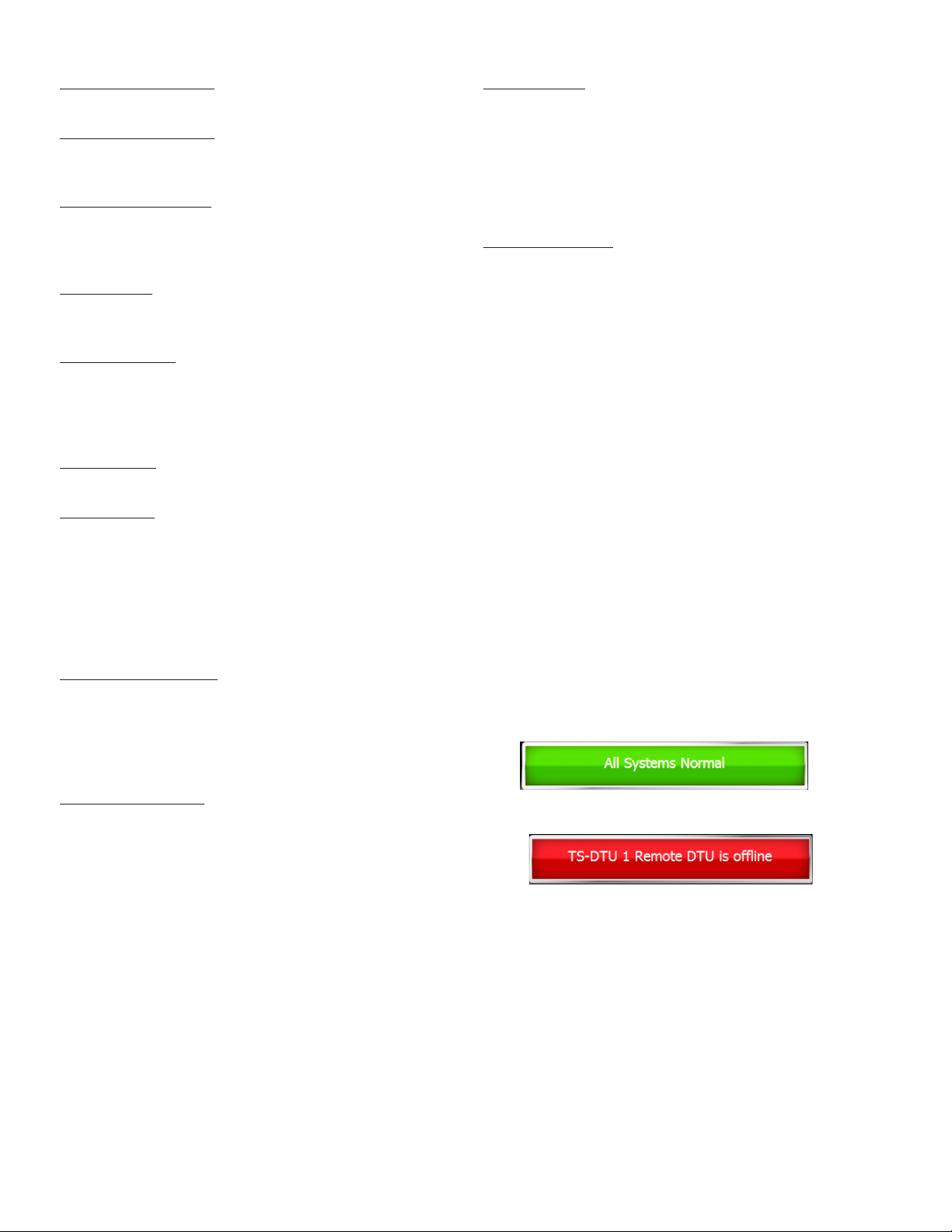
• Change the alarm button from showing normal:
to showing the alarm. i.e.:
.
Optionally, on alarm the system can:
• Sound the console’s internal alarm horn.
• Activate relay outputs and sound external alarm
devices.
• Print alarm reports.
• E-mail alarm reports to a specied destination.
• Notify remote monitoring software via optional
internal modem or Ethernet.
For help with troubleshooting alarms, refer to the
Troubleshooting chapter of the TS-550 evo Series
Programming Manual (000-2173).
5
Programming and Navigation
Console Navigation
The operating system is designed for easy navigation. Applications allow the user to modify programming options by
responding to on-screen commands. The following instructions show various operating system functions, so that issues
can be corrected efciently without interrupting dispensing or sales.
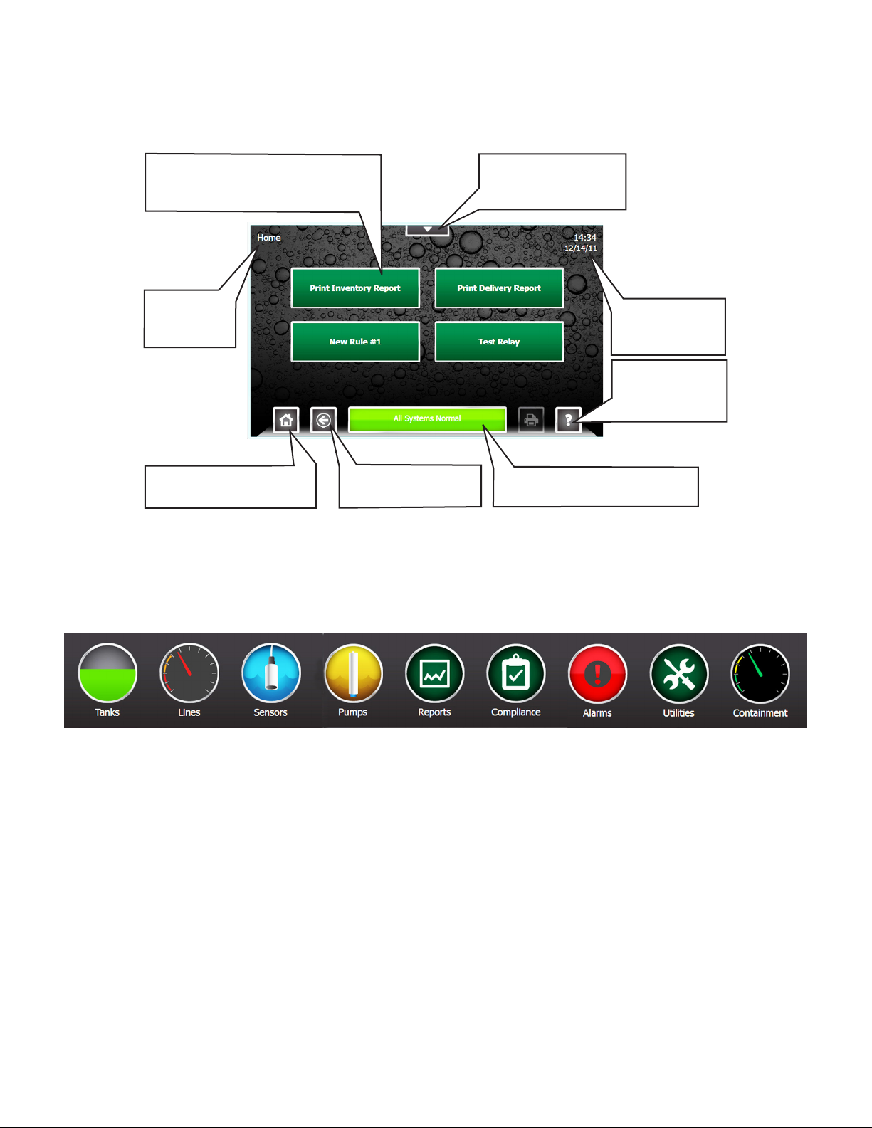
One-Touch Buttons – Run
customized and site-specic rules
for various console functions.
Shows which
screen is
displayed.
Home – This will return to
the screen shown here.
Navigation Buttons
There are many ways to navigate the applications of the TS-550 evo console. Listed below are buttons that will help you
navigate the functions of the console.
Back – Returns to
the previous screen.
Quick Jump Menu –
Allows rapid access
to console functions.
Shows current
system time and
date.
Help – Displays
context-sensitive
help information.
Status – When in Alarm, bar
turns red and describes alarm.
Quick Jump Menu (QJM)
The Quick Jump Menu was developed to simplify system navigation. From the Quick Jump Menu you can access sections
of the TS-550 evo with a few quick selections.
Quick Jump Menu
Note: Your console will display selections depending upon installed equipment.
Selecting the icon will take you to the summary screen for that item and allow you to access more detailed information.
Tank
s – The Tanks selection provides inventory information and control functions for the tanks and manifolds at a site
Lines – The Lines selection provides Line Status, Line Leak Test status, as well as Line control & calibration functions for
each line at a site.
Sensors – The Sensors selection provides Sensor status, and control functions for the sensors at a site.
Pumps – The Pump selection provides the status and control functions for all Pumps connected to the system using the
Turbine Pump Interface.
Reports – The Reports selection allow the user to generate any number of system and application reports.
Compliance – The Compliance selection provide detailed information regarding the compliance status of: Tanks, Manifolds,
Lines, and Sensors monitored by the system.
Alarms – The Alarms selection provide a list of current active alarms, as well as an alarm history and an application event
history.
Utilities – The Utilities selections provides access to the various setup, conguration, and system tools used to congure and
maintain the site.
• Page 8 list further information about these menu items
6
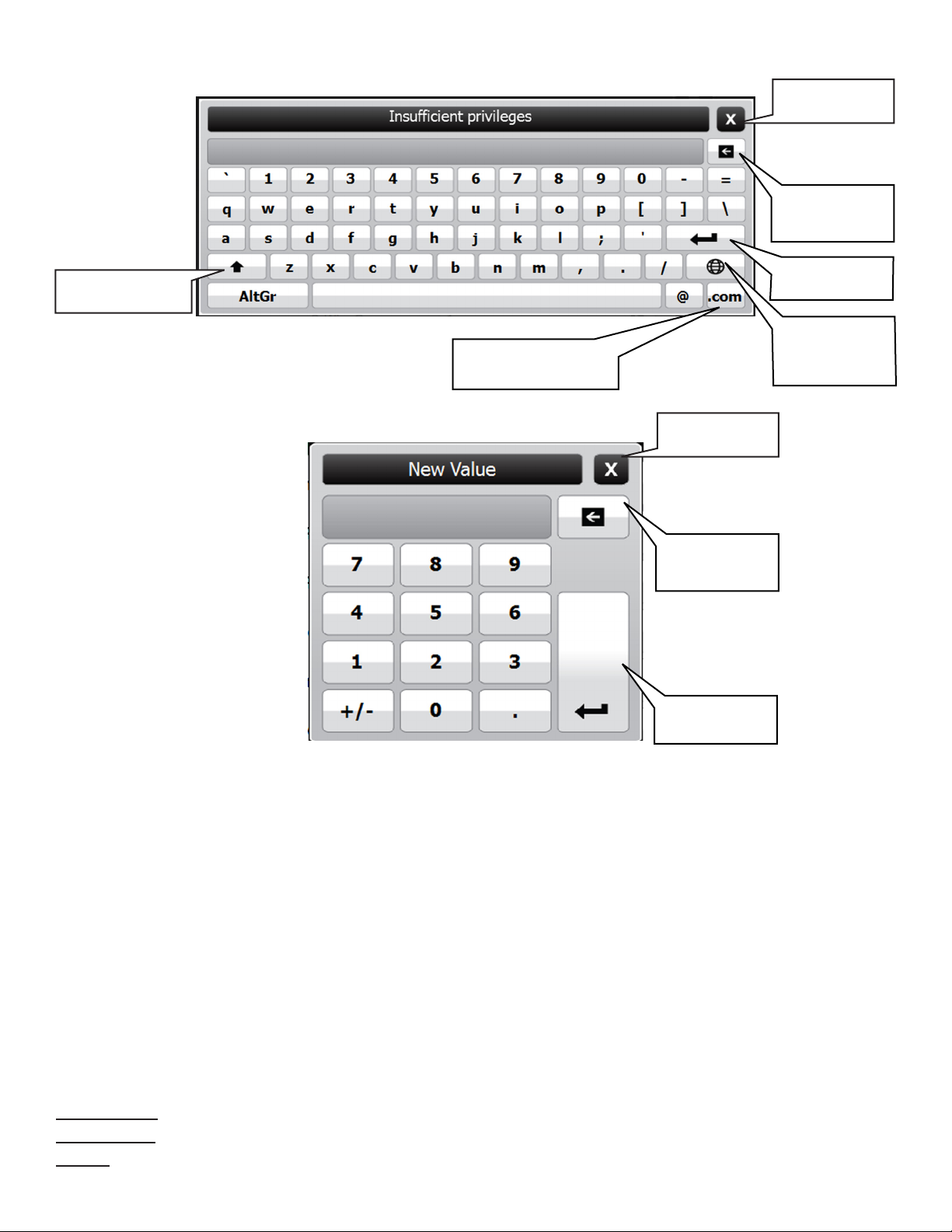
Text Entry Screen
Close Without
Saving
Erase Individual
Characters
Use Upper-Case
Characters
Number Entry Screen
Adds the .com extension
to an e-mail address
Save and Enter
Text
Use
International
Characters
Close Without
Saving
Erase Individual
Characters
Save and Enter
Numerals
User Role - Access Control
There are three levels of access into the console’s operating system: Guest, User, and Administrator. Each level will
allow an operator to access different features and controls of the console. This security feature prevents unauthorized
access to critical information and settings. The password for each access level can be adjusted by the Administrator. The
Administrator level is typically reserved for an Franklin Fueling Systems certied technician. User’s will be automatically
prompted for a password to access or change data as required.
The User Role icon displays the current access level allowed. White bars displayed in this icon indicate the access level.
Pressing the User Role indicator on your LCD display will return the system to Guest access level.
GUEST level: Guests are allowed to access menu options, check the system conguration and print reports. A GUEST
will not be able to modify the console’s settings.
USER level: Users are given access to more functions of the operating system so that they can perform line/tank leak
tests and reset line alarms.
ADMINISTRATOR: This level grants access to all areas of programming and setup conguration. The administrator
privilege is usually reserved for Franklin Fueling Systems certied technicians.
System Identication
In order to understand what sections of this manual apply to your system, you must be able to identify what Fuel
Management System you have and what Options and Applications it is running.
Model Number – Located on the front of the console.
Serial Number – Located on a sticker on the left side panel (along with Model number).
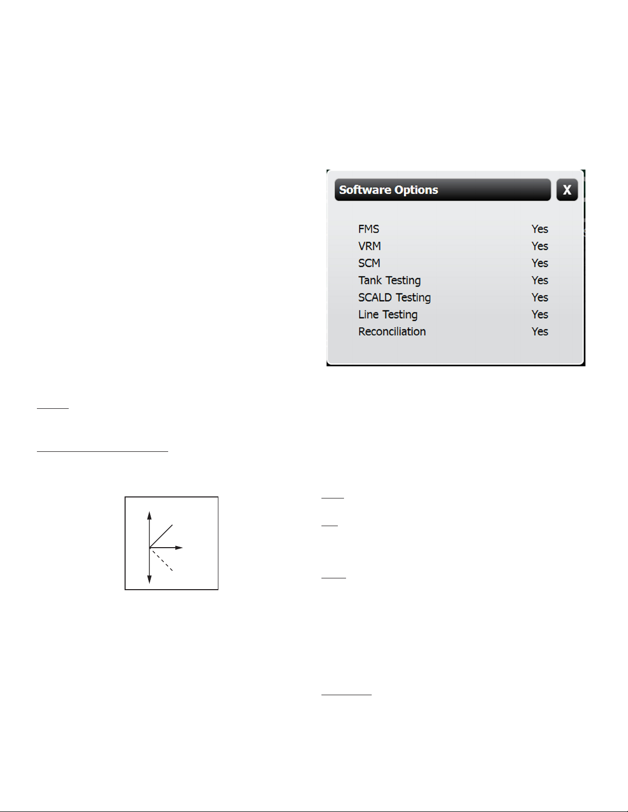
Options – To see what Applications and Options the system is running, press QJM>Utilities>System
7
Quick Jump Menu Selection Descriptions
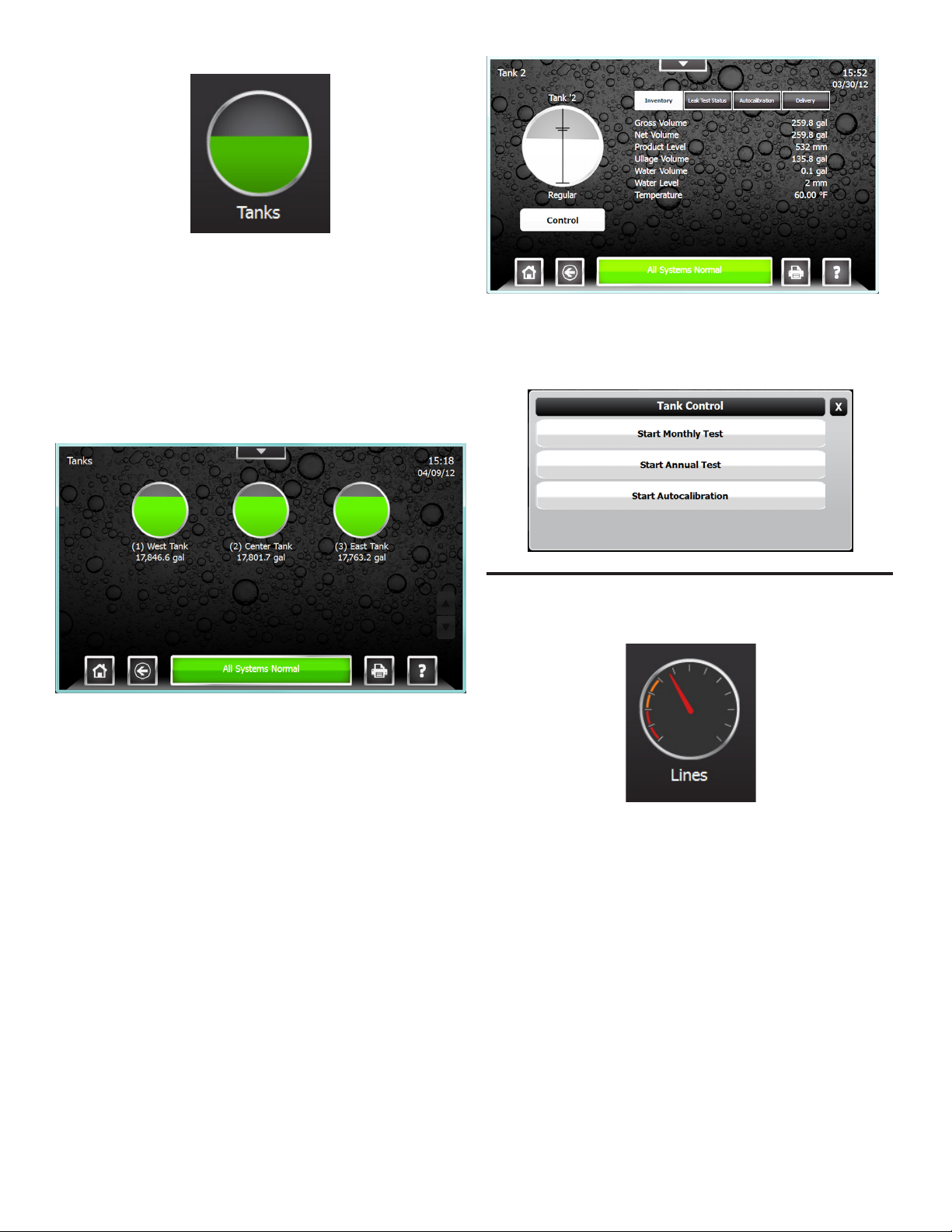
Tank Inventory Summary Screen
The Tank Inventory Summary screen displays a
graphical representation of the product and water levels in
the tanks and indicates any alarm conditions. The Product
name and current Volume are also displayed for each tank.
An alarm condition on the tank is also indicated here, if
present. Pressing the print button while on this screen will
print an Inventory Report for all tanks.
To access the Tank Inventory Summary screen select
Tanks from the Quick Jump Menu (QJM).
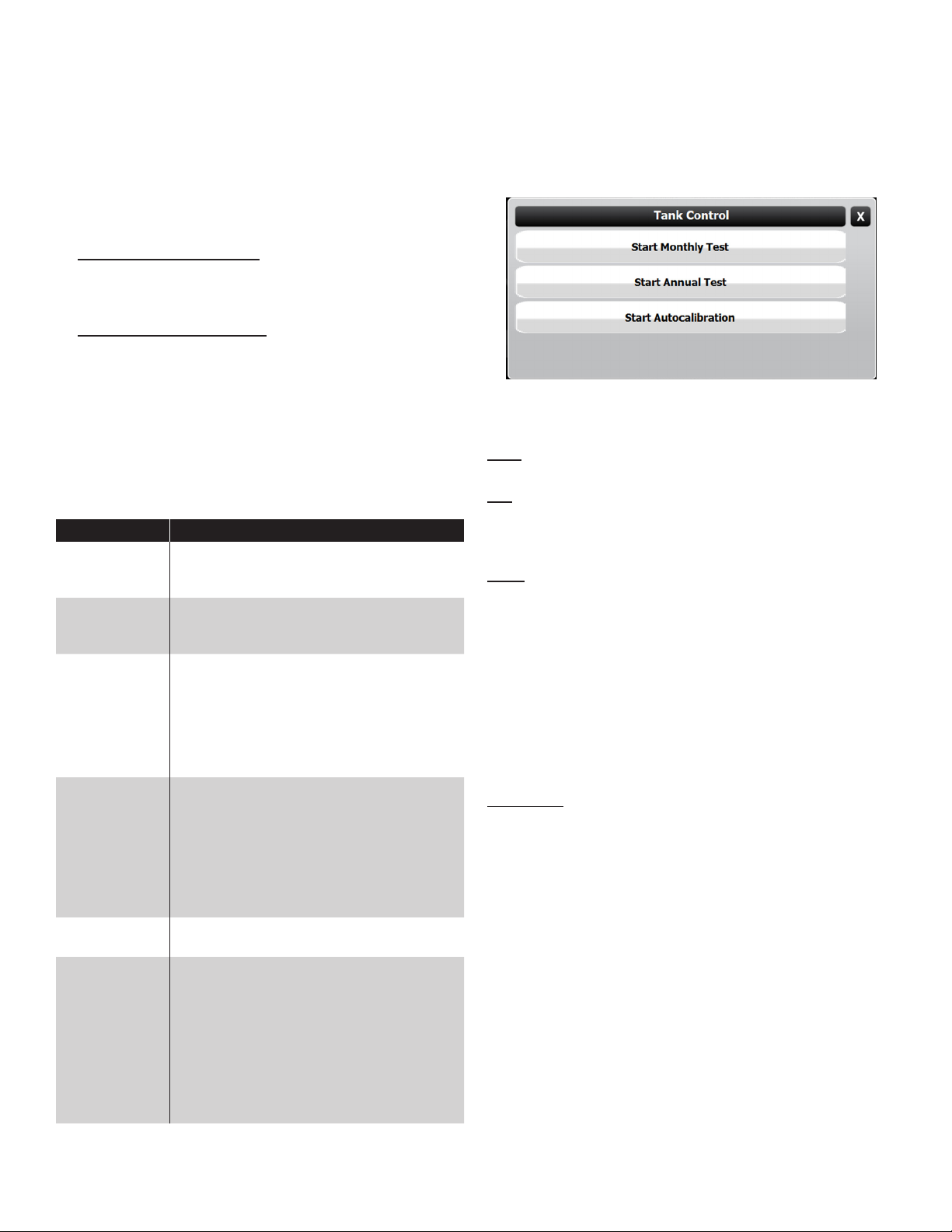
Tank Controls feature can be accessed using the Control
Button on the Tank Inventory Detail Screen. This will allow
authorized users and technicians to start tank tests or
autocalibration.
Tank Inventory Detail Screen
The Tank Inventory detail screen will provide detailed
information on product volume, level, temperature and
ullage space available in a particular tank. The level and
volume of any water will also be displayed. The hash
marks on the graphic indicate the various programmed
high and low alarm limits. An alarm condition on the tank is
also indicated here, if present.
The Tank Inventory Detail screen also provides details
regarding the tanks Static Leak Test status, Autocalibration
status, and Delivery history using the four tabs at the top of
the left hand column. Pressing the print button while on the
page will print an Inventory Report for just this tank.
To access the Tank Inventory Detail Screen select a tank
from the Tank Inventory Summary screen.
Line Status Summary Screen
The Line Status Summary screen displays a graphical
representation of the line pressures in each line and will
indicate any alarm conditions. The Line name and current
pressure reading are also displayed for each line.
To access the Lines Status Summary screen select Lines
from the Quick Jump Menu (QJM).
8
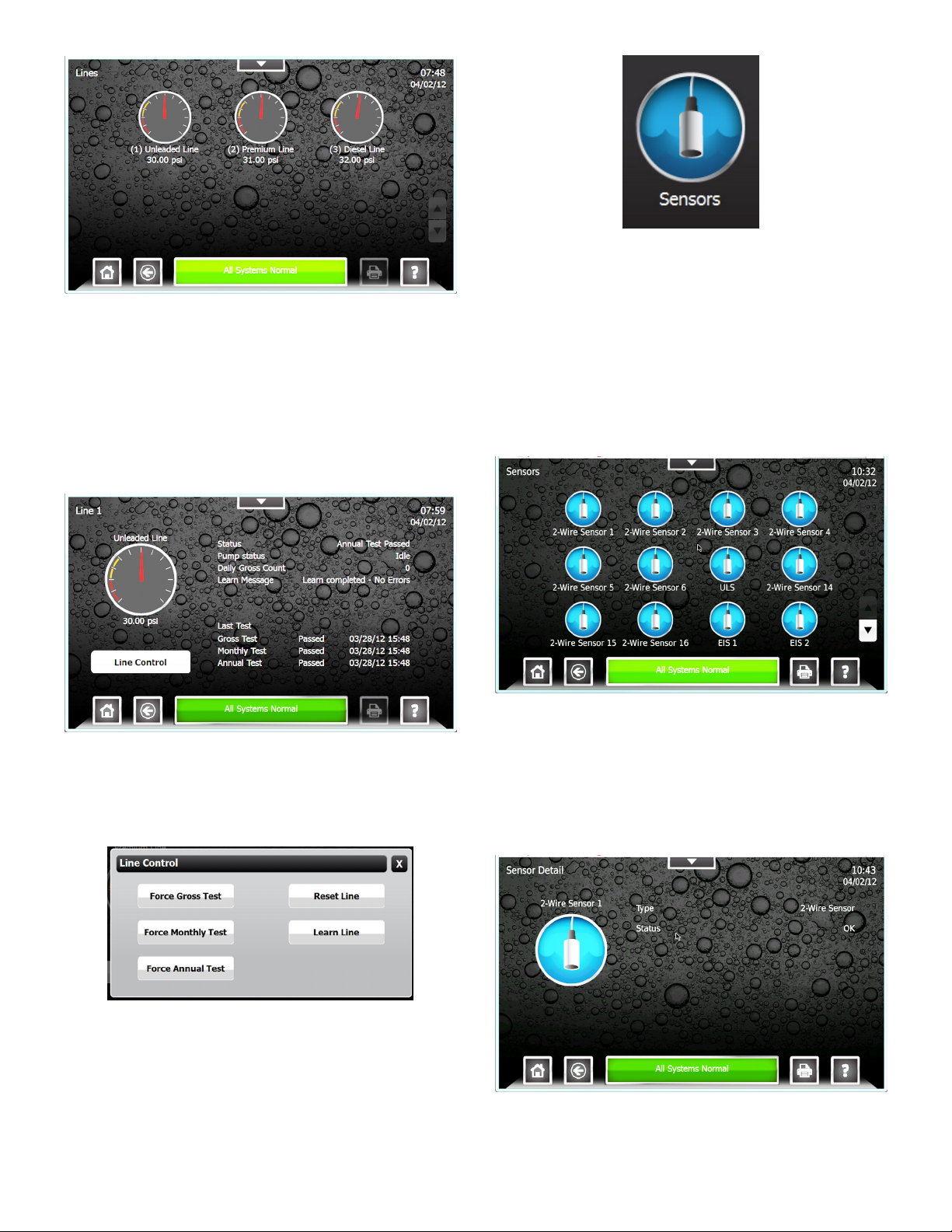
Line Status Detail Screen
The Line Status Detail screen will provide detailed
information on Line Leak Testing and the Line Status. The
Line status, Pump status, number of Gross Leak Tests
performed, Line Learn Messages, and the date and time
of the last line test completed. An alarm condition on the
Line is also indicated here, if present. From the Line Detail
screen Line Control can be accessed. To access the Line
Status Detail Screen select a line from the Line Status
Summary screen.
Sensor Status Summary Screen
The Sensor Status Summary screen displays a graphical
representation of a sensor, the name of the sensor and
will indicate any alarm conditions. Pressing the print button
from the screen will print a sensor status report for all of the
sensors.
To access the Sensor Status Summary screen select
Sensors from the Quick Jump Menu (QJM).
Line Controls feature can be accessed using the Line
Control Button on the Line Status Detail Screen. This will
allow authorized users and technicians to start line leak
tests, reset the line, and learn the line.
Sensor Status Detail Screen
The Sensor Status Detail screen will provide details on
the sensor type and the sensors current status. Any alarm
condition on the Sensor is also indicated here, if present.
Pressing the print button from this screen will print a sensor
report for that tank. To access the Sensor Status Detail
Screen select a sensor from the Sensor Status Summary
screen.
9
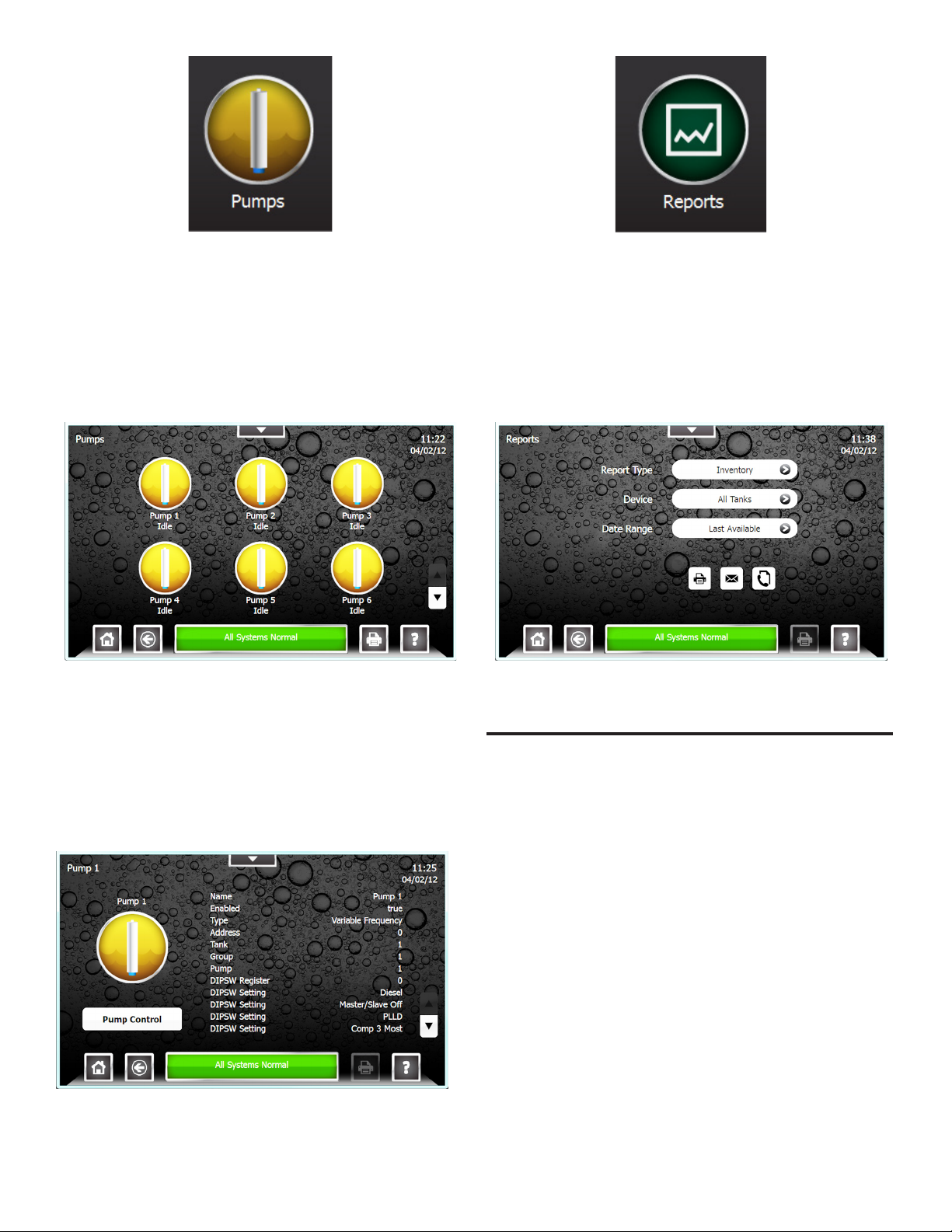
Pump Status Summary Screen
This screen displays a graphical representation of the
submersible pumps, the name of the pump, and an
indication whether the pump is running or not. An alarm
condition on the pump is also indicated here, if present.
Pressing the print button while on this screen will print a
Pump Status Report for all Pumps.
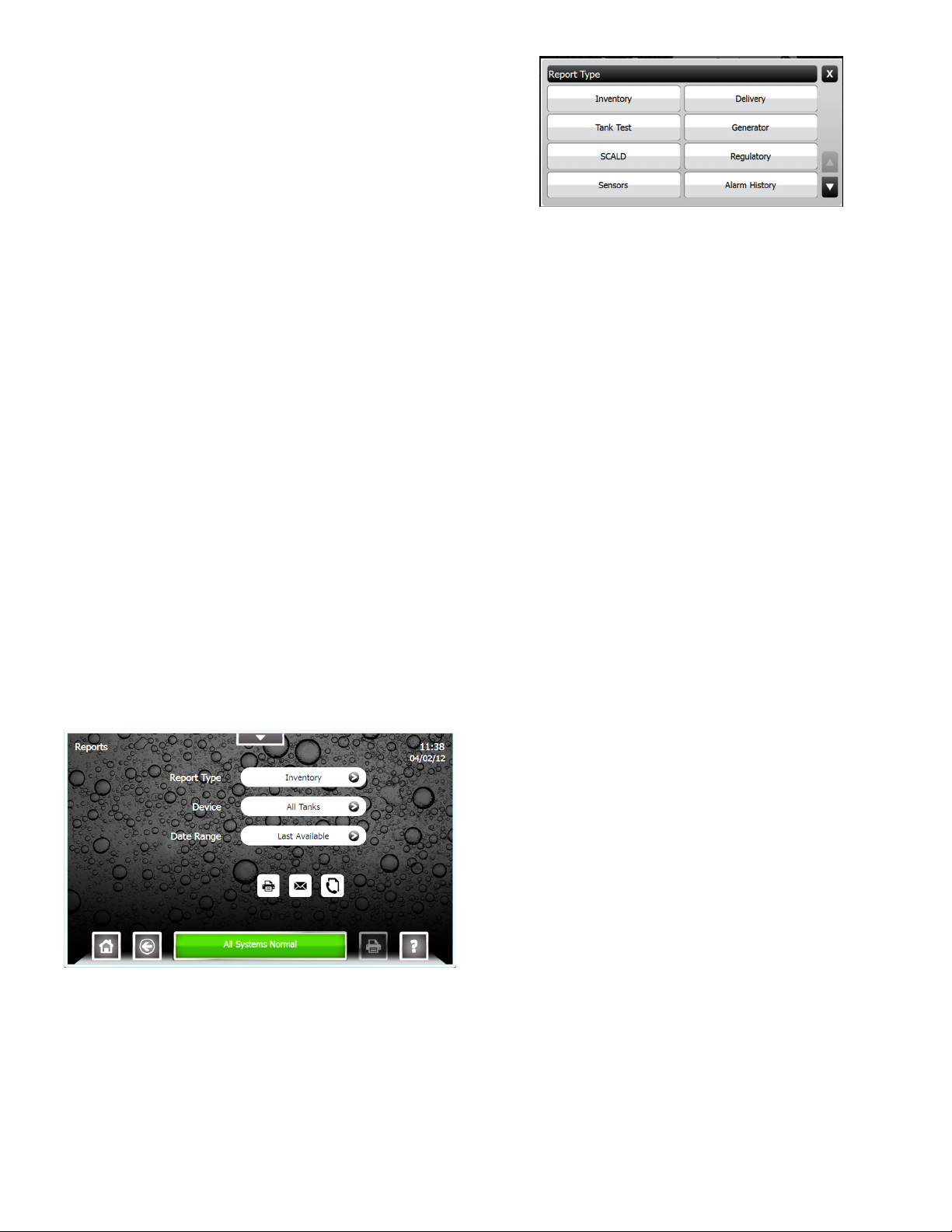
Report Generator Screen
The Report Generator screen is used to create a variety of
reports. The report options available depend on software
options and system conguration. The available reports
include: Alarm History, Application Event History, Setup,
Inventory, Delivery, Tank Test, SCALD, Line Test, Pump
Status, Reconciliation, Regulatory, and Sensor Status.
To access the Pump Status Summary screen select
Pumps from the Quick Jump Menu (QJM).
Pump Status Detail Screen
This screen provides a variety of information regarding the
pump and it settings. Information including: Pump Name,
Enabled/Disabled, Controller Type, Controller Address, the
tank the pump is installed in, and Pump Group. The screen
also includes status information such as Pump Running, has
the pump been forced off, and if a hook signal is present.
Pressing the print button while on the page will print a Pump
Status Report for just this tank.
To access the Report Generator screen select Reports
from the Quick Jump Menu (QJM).
Pump Controls feature can be accessed using the Control
Button on the Pump Status Detail Screen. This will allow
authorized users and technicians to reset the Pump
hardware and software.
10
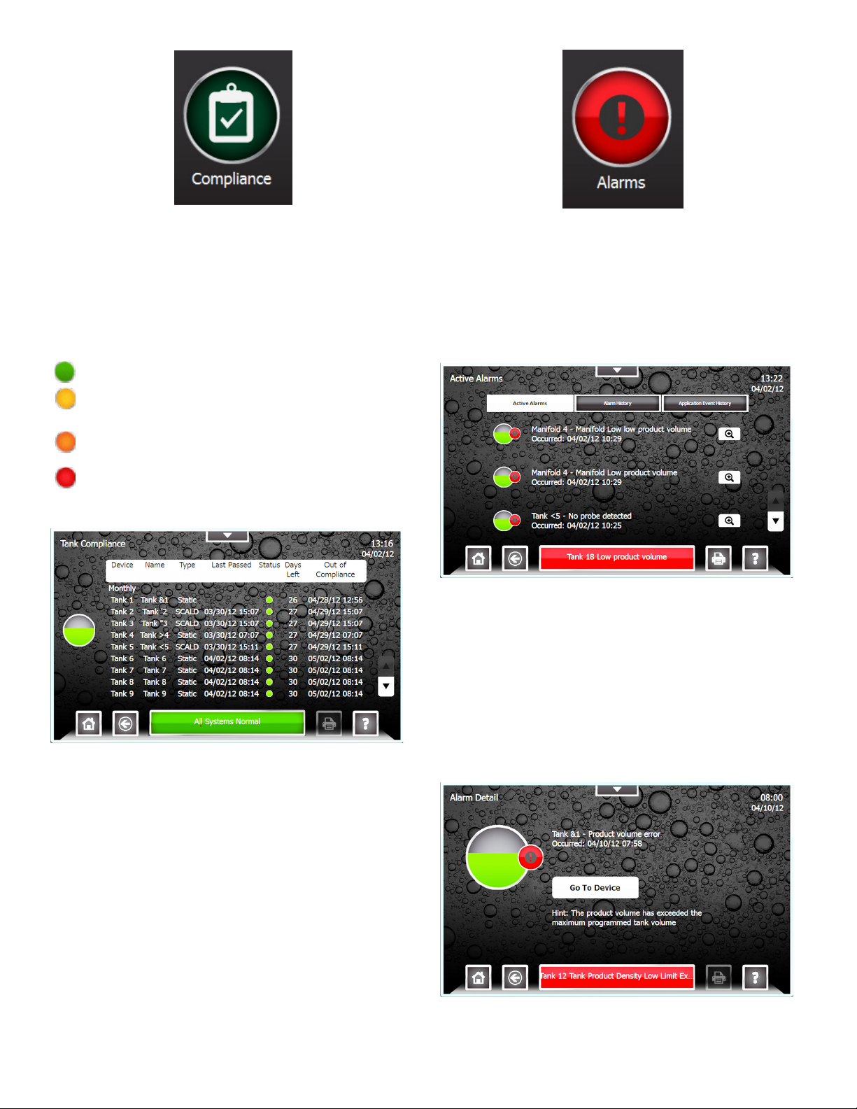
Compliance Screen
The Compliance screen displays regulatory status
information for Tanks, Manifolds, Lines, and Sensors.
Each page lists every device, the number of days
remaining and the date when that specic device will be
out of compliance. The screen will indicate compliance
concerns with a color coded status indicator.
Compliance Status
Compliant – The device is in compliance.
Compliance Alert – The device will be out of
compliance in 8 to 14 days.
Compliance Warning – The device will be out of
compliance in 1 to 7 days.
Compliance Alarm – The device is out of
compliance.
Tank Compliance Screen
Alarm Summary Screen
The Alarm Summary screen displays active alarms, an
alarm history, and an application event history. From the
alarm summary screen users can view currently active
alarms and review alarm and application event histories,
as well as access more details about active alarms.
To access the Alarm Summary screen select Alarms from
the Quick Jump Menu (QJM).
Active Alarm Detail Screen
The Active Alarm Detail screen provides detailed
information regarding an active alarm. These details
include the device, the date and time the alarm occurred,
and a description of the alarm. It will also provide hints for
recommended actions and precautions. Many alarms will
also have a “Go To Device” link which directs users straight
to the device to allow users to perform corrective actions.
Pressing help from this screen will provide further details
regarding the specic alarm. To access the Alarm Detail
Screen select an Alarm from the list of active alarms.
11
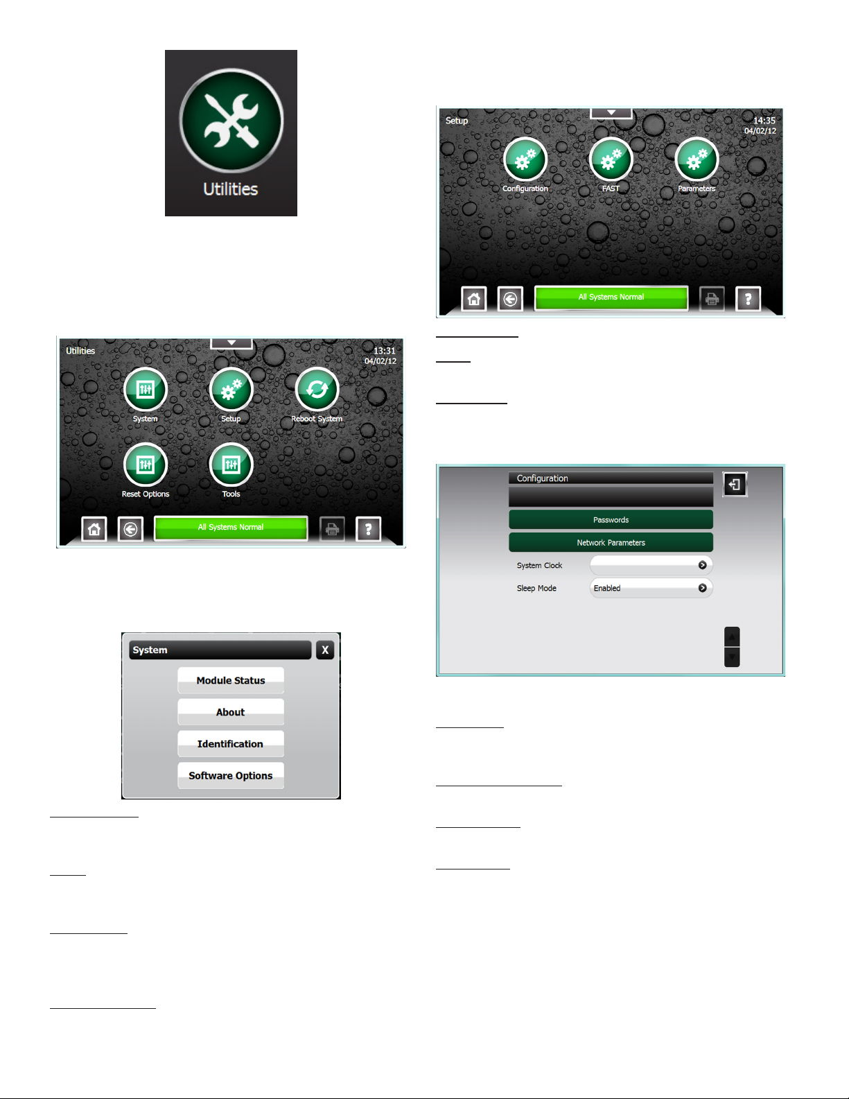
Utilities Screen
The Utilities Screen allows users and technicians to
change console conguration, setup, and preferences. It
also provides system diagnostic tools allowing technician
to test, troubleshoot and reboot the system.
Setup
Provide access to all of the systems setup and
conguration options.
Conguration - (see below)
FAST
This function is only for use by installers / programmers.
Parameters
See the Programming manual for detail regarding system
setup and conguration.
Conguration Menu
System
View Module Status, About the Console, System
Identication, and Software Options.
Module Status
Displays each module installed along with the modules’
Slot, State, and Software Version.
About
Displays contact information for Franklin Fueling Systems
and a note regarding Open Source software.
Identication
Displays system identication information including:
System Serial Number, Ethernet Address, Controller Serial
Number, and the system creation date.
Use the Conguration Menu to congure:
Passwords
Set the passwords for all access levels (Administrator Use
Only).
Network Parameters
Congure IP connection settings.
System Clock
Set the system date, Time, & Time Zone.
Sleep Mode
This will enable or disable the console blanking the display
after 5 minutes of inactivity.
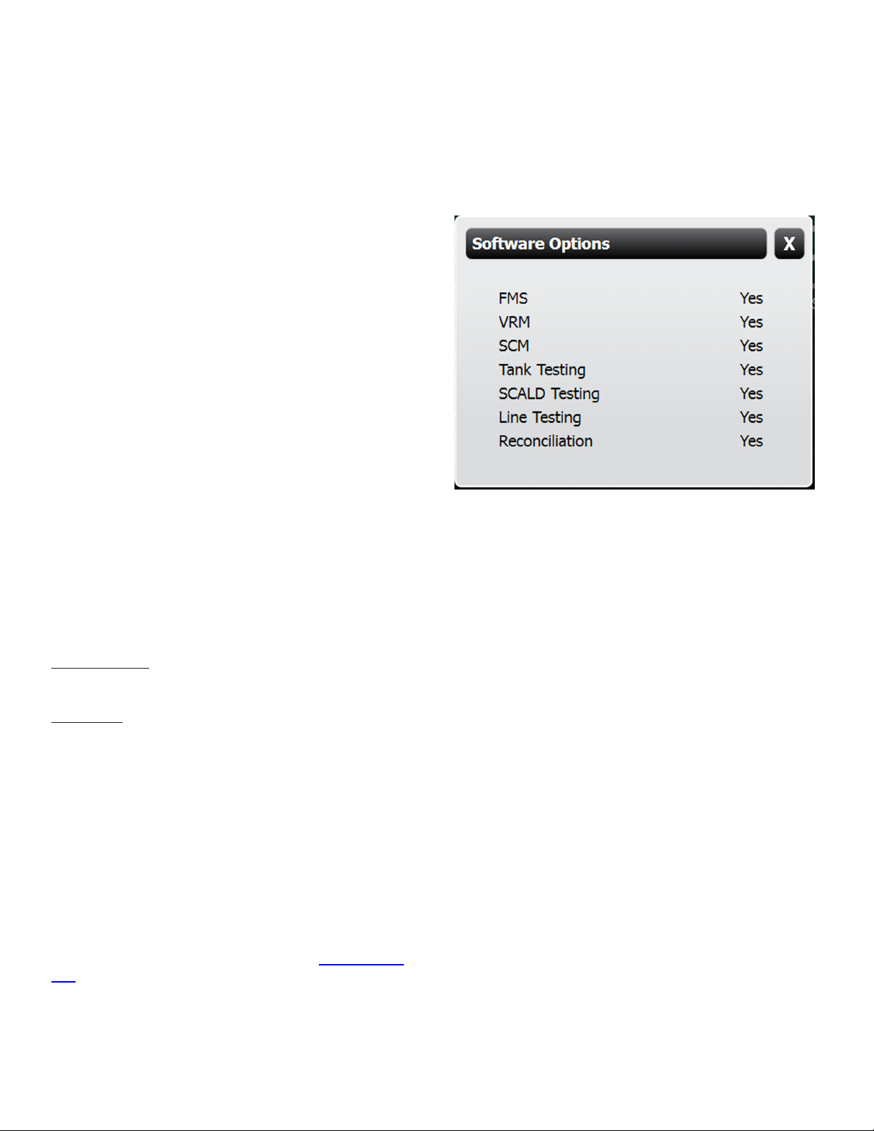
Software Options
Displays a list of optional software and wether they are
activated.
12
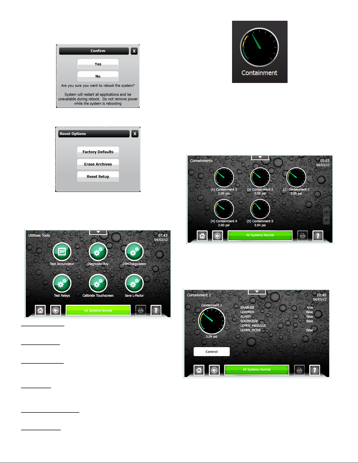
Reboot System
This will perform a system software reboot and requires an
administrator password.
Reset options
Reset to factory defaults, erase archives, or reset setup.
Secondary Containment Status Summary Screen
The Secondary Containment Status Summary screen
displays a graphical representation of the vacuum levels for
each Containment and will indicate any alarm conditions.
The Containment name and current vacuum reading are
also displayed for each line.
Access the Secondary Containment Status Summary
screen select Containments from the Quick Jump Menu
(QJM).
Tools
Provides access to various system tools such as:
Annunciator, Test Relays, generate a Diagnostic Key,
access DIM Diagnostics, Test Relays, or Calibrate the
touch screen.
Test Annunciator
Tests the operation of the internal alarm.
Diagnostic Key
Enters Diagnostic Mode (Certied technician access only).
DIM Diagnostics
Allows technician to interface with the Internal DIM
settings.
Test Relays
View relay state and test operation (read screen caution
notice)!
Calibrate Touchscreen
Enables re-calibration of the touchscreen.
Save L-Factors
Allows technician to save line factors.
Secondary Containment Detail Screen
The Secondary Containment Detail screen will provide
detailed information on Secondary Containment Testing and
the Containment Status. From the Secondary Containment
Detail screen Containment Control can be accessed.
13

Containment Control features can be accessed using
the Control Button on the Secondary Containment Detail
Screen. This will allow authorized users and technicians to
learn the containment, reset, or disable the containment.
Printing Reports
Internal Printer
An internal printer is optional on TS-550 evo console.
The printer is a thermal style printer that requires thermal
paper. For paper loading instructions, refer to the Routine
Maintenance chapter in this manual.
External Printers
External printing is accomplished via USB. No software
drivers need to be installed to print via USB. Connect the
USB cable to the printer and the USB port on the console.
The unit is now ready to print. Approved printer are
updated regularly, please see our web page for details.
Note: The setup will need to be changed so the printer
option is 0, save the conguration, connect the printer and
cycle the power of the tank gauge.
Print Button
The Print Button will print the data displayed
on the LCD when available.
Reports Options
The following reports are available for the different optional
Applications. Each report allows you to select the date
range of data you wish that report to contain.
Reports
Report Description
Alarm History
Application
Event History
Setup A printout of the system programming.
Inventory Complete level, volume, temperature
Delivery Start and ending level and volume
Tank Test Annual and monthly static tank testing
SCALD 24hr continuous monthly tank testing
Lines Gross, monthly and annual line tests.
Regulatory Complete compliance report for all
Sensor Alarm status of all monitoring sensors.
A history of the Alarms that have
occurred.
A history of the Application Events that
have occurred.
and ullage info for each tank.
information and total amount delivered.
results. (tank testing option required)
results. (tank testing option required)
(line leak option required)
tanks, lines, sensors.
14

Tank Testing
There are two types of Tank Testing available in the Fuel
Management Systems: Static and SCALD.
Static tests are run during quiet times when the tank is
thermally stable and the site is closed so that no dispensing
or deliveries will occur. There are two types of Static tests:
Monthly (0.2 gph) and Annual (0.1 gph). Static tests can
be scheduled to run on a Daily, Weekly or Monthly basis in
the Setup menu (Administrator use only). They can also be
started on demand from the tank detail screen. Make sure
that all testing conditions are met before starting a Static
Tank Test.
SCALD (Statistical Continuous Automatic Leak Detection)
tests run 24 hours a day and look for periods of quiet time
when the tank is thermally stable and no dispensing or
deliveries are occurring. These quiet periods are collected
and analyzed and the tightness of the tank is determined.
SCALD tests will update whenever possible and can
be setup to print automatically when they do. The more
common method is to schedule the latest SCALD test to
print out once a week, saving a signicant amount of paper
because SCALD tests can be generated multiple times a
day on a quiet tank.
Static and SCALD tests run independently of each other
and can be run at the same time. A SCALD test will likely
complete during the time that the Static test is running.
Static Testing
Terms
Threshold
– Test results must be within these
programmable limits to pass a leak test. There are Monthly,
Annual and Sentinel Mode Thresholds.
Sentinel Mode – Sentinel mode is designed to monitor the
product levels in your tank(s) when there isn’t supposed to
be any dispensing.
Condence – Level of testing
sensitivity indicating the probability
that the test will detect a leak. Higher
condence percentages will produce
more sensitive test results. Check
local regulations to verify acceptable
condence levels.
Slope (Tank Testing Reports) – A
ratio of the calculated rate of change
to the time the rate is measured.
Slope is affected by leaks and by
Time
Flow
(+) slope
No Leak
(–) slope
many other sources of interference.
A negative slope or decrease
indicates loss of product volume. A
positive slope or increase indicates a
rise in product volume.
All Franklin Fueling Systems Fuel Management Systems
meet the requirements of the U.S. Environmental
Protection Agency (EPA/530/UST-90/006 test protocol) for
Automatic Tank Gauging Systems (ATGS). The system(s)
also meet the requirements for Annual Tank Tightness
Testing for 0.1 gal/hr leaks of the National Work Group on
Leak Detection Evaluations (NWGLDE). Third Party Testing
Laboratory test results (for standard static tank leak tests)
are also available at http://nwglde.org/.
Why Test the Integrity of a Tank
In compliance with federal, state and local regulatory
policies, all tanks must be monitored for leaks due to
environmental and public safety/health concerns. Tank
tightness testing determines if there is a leak.
15
Tank Testing Requirements
Static Tank Testing is a standard feature of the Fuel
Management System. SCALD is an option that can be
ordered when purchasing the console or after initial
purchase by using the part number TS-TT.
Test Types
This system is designed to perform two types of static tests
to comply with regulatory policies.
• 0.1 GPH Annual Leak Test — Detects a rate increase or
decrease of product in the tank, other than dispensing
(no testing during dispensing), at a rate greater than 0.1
gallons per hour.
• 0.2 GPH Monthly Leak Test — Detects a rate increase
or decrease of product in the tank, other than
dispensing (no testing during dispensing), at a rate
greater than 0.2 gallons per hour.
Ideal Testing Conditions
Tank and environmental conditions play an important role
in passing results. Consider the following items when
scheduling or manually forcing a static leak test:
Variable Explanation
The level in the tank must submerge at least
Product Level
Temperature
Stability
Time of Day
Deliveries
Dispensing
the lowest RTD (temperature sensor) inside
the probe shaft.
A tank with more product inside is likely to be
stable thermally and allow for higher quality
results.
This variable ties in with temperature stability.
Though not likely, product in the tank may
dramatically rise and fall in temperature from
dawn to afternoon and then from dusk to night.
Typically, thermal issues affect Aboveground
Storage Tanks more often than Underground
Storage Tanks.
A period of time is required to wait without a
delivery between the last delivery and testing.
The time to wait is 4 hr 9 min for a 0.2 GPH
and 5 hr 18 min for a 0.1 GPH after a delivery
(in accordance with third party testing). This
time will allow the product to settle. If the wait
time is not observed, then the test may abort
or fail.
If dispensing occurs during a test, that test will
be aborted.
How to Manually Start Static Tests
This procedure requires User level privileges.
1. Starting at the Home screen, open the Quick Jump
menu.
2. Select Tanks and then click on which tank to start
a test.
3. Press the Control button.
4. Press the Test Type and choose either Monthly or
Annual.
Static Test Results
Pass
– A passing result ensures the integrity of the tank is
good.
Fail – Test failure will be indicated by a Warning light and/or
annunciator. Additionally, a report may print (if the console
is programmed to do so, see the TS-550 evo Programming
Guide p/n 000-2173)
Abort – The result has been stopped due to variations in
oat level and/or product temperature that are outside of
the leak test threshold. This may be caused by:
• Dispensing
• Loss of Probe Signal
• Delivery
• Rapid Temperature Change
• Theft
• Product Lower than the lowest RTD
• Pump Started
Incomplete – When the test does not collect enough data
before the programmed time limit ends, the test will be
Incomplete. When it’s necessary to obtain valid results for
compliance reasons, start the test manually.
16
Test Time
The test should be scheduled or manually
forced when the test will not exceed the
maximum leak test time. If the maximum time
is surpassed, an Incomplete result is likely
to occur. If scheduling or manually forcing a
test, take into account what the sites hours
of operation are to avoid a dispense during
testing. Doing this will prevent aborted and
incomplete tests.
Statistical Continuous Automatic Leak
Detection (SCALD)
SCALD (Statistical Continuous Automatic Leak Detection)
runs 24hrs a day performing 0.2 GPH tests on tanks at
sites that do not have enough quiet time to complete static
tests (some static tests may take up to eight hours to
complete).
SCALD Testing is available only if the option for Tank
Testing is enabled. This option can be ordered when
initially purchasing the console or afterwards. The part
number for this option is TS-TT for the TS-550 evo.
Why Continuously Test Tank Integrity
In compliance with federal, state and local regulatory
policies, all tanks must be monitored for leaks due to
environmental and public safety/health concerns. Tank
Integrity Tests determine whether there is a leak.
Since SCALD continuously runs statistical tank leak tests
during the inactive periods between product deliveries and
dispensing, it is particularly useful for:
• Operations that are open for business on a continuous
(24 hours, 7 days a week) schedule
• Operations that are open for business on a two-shift
schedule and where deliveries may occur at any time
during non-business hours (normally schedule tank leak
tests may require up to 8 hours of inactivity).
Terms
Qualify
required to contain prior to testing according to the
programmed “Qualify” parameter.
Slope (Tank Testing Reports) – A ratio of the calculated
rate of change to the time the rate is measured. Slope
is affected by leaks and by many other sources of
interference.
A negative slope or decrease indicates loss of product
volume. A positive slope or increase indicates a rise in
product volume.
– The percentage of product that the tank is
Flow
(+) slope
Time
No Leak
(–) slope
SCALD Testing Requirements
To perform SCALD testing, the SCALD software must be
enabled. To verify that the software is enabled:
1. Starting at the Home screen, open the Quick Jump
Menu.
2. Select Utilities from the QJM then select System.
3. Press the Software Options Button.
4. Under Software Options, Tank Testing will appear.
A “yes” in the Enabled column indicates that the
software has been purchased and is enabled.
When SCALD Tests
SCALD works by collecting quiet intervals in-between
dispensing. A “QI” is obtained when a thermally stable tank
is idle for 20 minutes with no dispensing, no deliveries
and no other movement of the probe oats. Once four QIs
are collected, the console will analyze the data and either
Pass, Fail, Incomplete, or Abort that test. The four QIs can
be collected over a period of several days or weeks.
SCALD Results
Pass
– A passing result ensures the integrity of the tank is
good.
Fail – Test failure will be indicated by a Warning light and/or
annunciator. Additionally, a report may print (if the console
is programmed to do so, see the TS-550 evo Programming
Guide p/n 000-2173).
Abort – The result is due to variations in oat level and/
or product temperature that are outside the leak test
threshold. This may be caused by:
• Dispensing • Rapid Temperature Change
• Delivery • Product Lower than the
lowest RTD (Resistance
Temperature Detector)
• Theft • Pump Started
• Loss of Probe Signal
Incomplete – When the test does not collect enough data
before the programmed time limit, the test is Incomplete.
When it is necessary to obtain valid results for compliance
reasons, start the test manually.
17
Reasons Why SCALD May Not Complete
• No Quiet Time
• SCALD needs four 20 minute QIs in order to
complete a test. These QIs are normally found in the
early morning hours. If the site is so busy that there
are no 20 minute periods of no dispensing, then
SCALD will not be able to complete a test.
• Temperature Instability
• If a site is receiving deliveries frequently and the
temperature of the fuel being delivered is several
degrees hotter/colder then the fuel in the tank,
SCALD will not be able to collect data due to thermal
instability interrupting quiet time. The temperature of
the fuel cannot change more than .01° F during a 20
minute QI.
• If a pump control relay is stuck closed and the pump
is running all of the time, the temperature in the tank
may be much higher than in the other tanks. Due to
this high temperature and the fact that the pump is
running, no QIs will be collected.
Note: On rare occasions conditions can arise that prevent
SCALD from getting enough QIs to complete a test.
3. Select the Date Range desired.
4. Press the checkmark to start report printi
Viewing SCALD results
From the Quick Jump menu, select Compliance and then
select Tanks.
Tank Leak Test Reports
Reports that contain leak testing data and results may be
printed from the console or generated/printed using TSA.
Printing Tank Leak Test Reports
LCD
1. Starting at the Home screen, open the QJM and select
Reports.
2. From the Report Type menu select either the Tank Test
(for static reports) or SCALD for continuous reports.
18

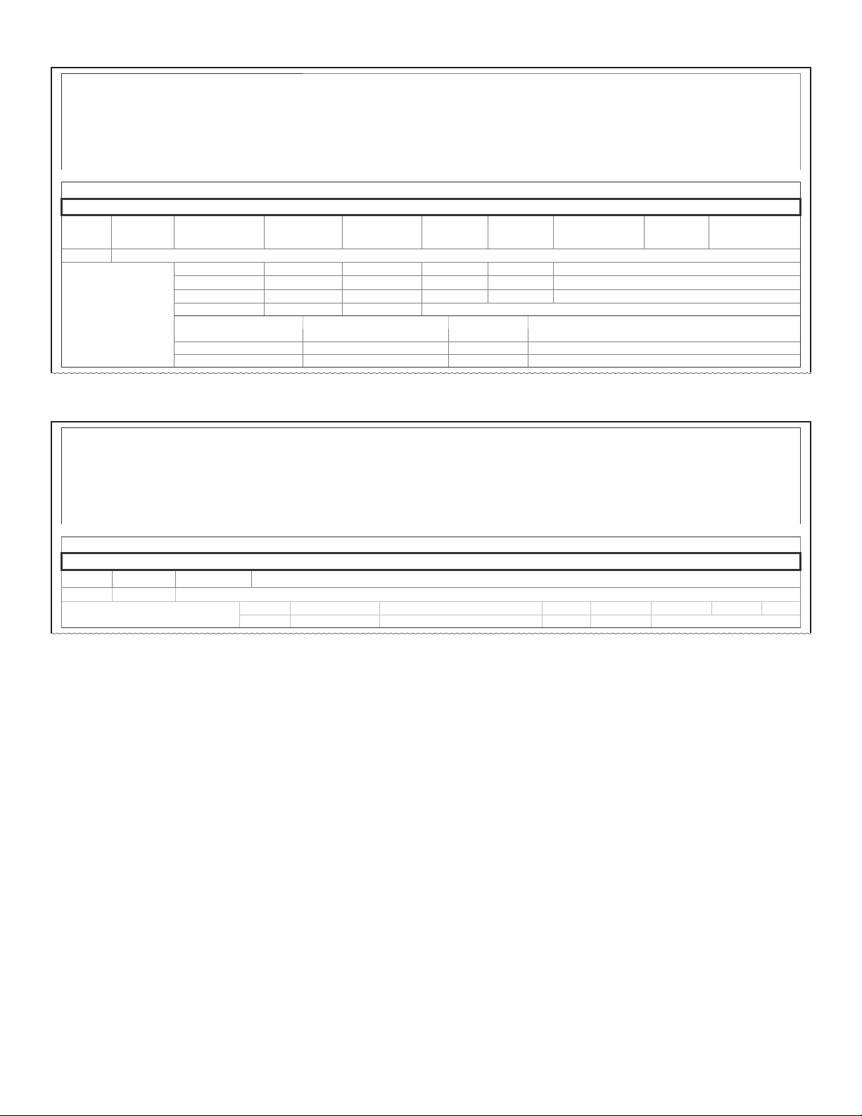
Sample Tank Leak Test Reports from Internal Printer
Site ID 1
Site ID 2
Site ID 3
Site ID 4
Site ID 5
Date Time
Tank Test Report SCALD Report
Specied Time Frame Specied Time Frame
Volume: (gal) programmed
Length: (in) programmed
Temperature: (F) programmed
TANKS
Tank #
Product #
Maximum Capacity
#.##
Begin Time
Date Time
Begin Gross
#.#
Begin Net
#.#
Begin Level
#.#
Begin Temperature
#.#
Begin Water Level
#.#
Begin Water Vol
#.#
End Time
Date Time
End Gross
#.#
End Net
#.#
End Level
#.#
End Temperature
#.#
End Water Level
#.#
End Water Vol
#.#
Last Delivery
Test Type
Monthly
Threshold
#.##
Leak Rate
#.##
Result
Pass/Fail/Abort/Incomplete
Capacity
#.##
Details
Time
Date Time
Net Volume
#.#
Temperature
#.#
Level
#.#
Time
Date Time
Net Volume
#.#
Temperature
#.#
Level
#.#
Site ID 1
Site ID 2
Site ID 3
Site ID 4
Site ID 5
Date Time
Volume: (gal) programmed
Length: (in) programmed
Temperature: (F) programmed
TANKS
Tank #
Product #
Maximum Capacity
#.##
Started
Date Time
Result
(Pass)
Slope
#.############
Status
#.#
Ended
Date Time
Vol %
#.##
Type
(Monthly)
19
Example External Tank Leak Test Report from Web Browser Interface
Site ID 1
Site ID 2
Last Available
Site ID 3
Site ID 4
Tank Test Report
Site ID 5
STATIC TEST
TANKS
Name
Tank # #.##
Max
Capacity
Time
Started Date Time #.# #.# #.# #.# #.# #.#
Ended Date Time #.# #.# #.# #.# #.# #.#
Last Delivery Date Time Test Type (Monthly) Leak Rate #.## Result (Pass)
Threshold Programmed Capacity #.##
Net Volume Temperature Level Time
#.## ##.## #.## Date Time
#.## ##.## #.## Date Time
#.## ##.## #.## Date Time
Gross
Volume
Net Volume
Site ID 1
Site ID 2
Last Available
Site ID 3
Site ID 4
Tank Test Report
Site ID 5
Product
Level
Temperature
Water
Level
Date Time
Water Volume
Date Time
Name Product Max Capacity
Tank # Product # #.##
SCALD TEST
TANKS
Started Date Time Result (Pass) Slope #.# Status #.##
Ended Date Time Volume Quality Percent #.# Test Type (Monthly)
20
Line Leak Testing
Overview
Line Leak Detection is available only if the option for Line
Testing is enabled. This option can be ordered when
purchasing the console or after the initial purchase by
using the part number TS-ELLD. An AC Input, 4-20mA, and
either a relay module or the use of TPI will also be required
to perform Line Testing.
Line Leak Testing for all T5 series FMS consoles use
software rules to automatically run tests. Tests may be
started manually from the console or remotely using TSA.
AutoLearn software monitors line conditions by conducting
a multitude of electronic line pressure sensing tests.
Line Leak Detection is required in many areas to monitor
for potentially hazardous environmental contamination. In
the event of a leak, the system may provide positive pump
shutdown (to prevent further contamination) and display an
indicator light and on-screen description of the condition as
console alarm notications. A high intensity remote alarm
may also be used if applicable. After installation, the user
of the system must monitor the system to ensure that any
leak alarm and pump shutdown (indicating a line leak) is
dealt with promptly.
Line Leak Testing Requirements
To perform Line Leak testing, the Line Leak software
must be enabled. To verify that the Line Leak software is
enabled:
1. Starting at the Home Screen, open the Quick Jump
Menu.
2. Select Utilities from the QJM then select System.
3. Press the Software Options Button.
The LS500 LLD system can detect a leak from the check
valve in the pump to the solenoid valve at the dispenser —
assuming no other normally closed valve is in the pipeline
system. This system does not detect leaks from the fuel
storage tank. The LS500 should be used in applications
where site conditions are in accordance with Third Party
testing (as listed in the NWGLDE section of this chapter).
Terms
Piping Modulus – This is the maximum pipe capacity that
may be tested in accordance with the 3rd Party Approval,
regardless of pipe diameter.
Transducer – An electronic pressure sensing device placed
in the line that communicates with the console..
Certications – 3rd Party Approvals
TS-LS500 AutoLearn Pressurized Electronic Line Leak
Detection as of May 19th, 2006 has been approved by a
third party for leak detection of rigid and exible piping.
National Work Group Leak Detection Evaluations
(NWGLDE)
This data can be referenced on the abbreviated version
of the 3rd Party Certication performed by Ken Wilcox
Associates, located on the NWGLDE site: http://nwglde.
org/.
4. Under Software Options, a Line Testing row will appear.
A “Yes” in the Enabled column indicates that the
software has been purchased and is enabled.
21

Test Cycles & Types
Once installed, calibrated and enabled, the LS500 will start a cycle of tests after the hook signal becomes inactive (i.e. a
nozzle is hung up). The transducers then monitor line pressure to ensure that pressure is sufcient to proceed with the
cycle. A Gross (3.0 GPH) Leak Test will begin immediately following the pressure test, if these options are enabled in setup.
When the Gross Test is complete with a pass result, the system will wait 30 minutes prior to monitoring the line for thermal
stability. When it determines that the line is stable, another Gross Test will be performed directly followed by a Monthly
(0.2 GPH) Leak Test. When the Monthly Test is complete with a pass result, the system then monitors the line for thermal
stability once again. When that the line is stable, another Gross Test will be performed followed by an Annual (0.1 GPH)
Leak Test. When the Annual Test is complete with a pass result, the system then waits 45 minutes prior to restarting the
cycle again.
Test Type Description
Pressure Up
Dispenser Pressure
Catch Pressure
Gross (3.0 GPH) Leak
Thermal Wait Time
Monthly (0.2 GPH) Leak
Annual (0.1 GPH) Leak
Line Learned but Not Enabled
Sudden Pressure Loss
Extended Pump Run
High Pressure
A pressure up test will monitor line pressure from a static line to when the pump is turned on.
Dispenser pressure is tested with the hook applied to ensure that line pressure does not drop too
low while dispensing. This feature can be enabled/disabled in the programming.
When the dispenser hook is dropped and the pump turns off, line pressure decay is monitored and
compared to a learned decay. This test will not cause the pump to shut down — alarm only.
The Gross Test will begin after every dispense when the line is enabled or after every 45 minutes
of quite time (no dispensing or pump running) following a line pressure test. In ideal conditions, this
test will take approximately 5 minutes to complete. In the event of a failure, the system will attempt
to run the test again after 5 minutes. After two failures an indicator light and alarm will turn on and
the pump will be shutdown. A dispense or pump shutdown by another application during this test
will cause an Abort Alarm. This test can be enabled/disabled in the programming.
Before initiating a precision test, the LS500 will monitor the line for thermal variations. Testing for
thermal variations takes 1½ to 10 hours of inactivity.
If this option is enabled in the programming, the test will follow a thermal wait period and line
pressure test. In the event of a failure, the system will attempt to run the test again without
waiting. Upon three failures, an indicator light and alarm will turn on and the pump will shutdown if
programmed. A dispense or pump shutdown by another application during this test will cause an
Abort alarm. This test can be enabled/disabled in the programming.
If a line is learned and not enabled within a preset amount of time, then the console will show a
warning that the line is not enabled. This is to show that the line is not being monitored for leaks.
This is a continuous test that runs in the background. An alarm will occur if line pressure drops too
fast.
The LS500 will detect all hook signals (if wired properly) and the time that they remain active. If
the hook signal is active for too long, the console will indicate this condition with an alarm light and
sound.
If line pressure exceeds the maximum allowable pressure, the pump will shut down and an alarm
will light and sound. This test will run continuously when the line is enabled.
How to Manually Start Line Leak Tests
This procedure requires User level privileges.
1. Starting at the Home Screen, open the Quick Jump Menu.
2. Select Lines from the QJM.
3. Select the line to test.
4. Select Line Control.
5. Select the Test Type, either Force Gross, Force Annual or Force Monthly.
22

Line Test Results
Pass
– A passing result ensures that the line is free of
leaks; any variation in product stability is within permissible
thresholds.
Fail – Test failure will be indicated by an alarm light and/or
annunciator. Additionally, a report may print (if the console
is programmed to do so, see the TS-550 evo Programming
Guide p/n 000-2173).
Abort – There may not be an indication of an abort for
some tests. If a line is disabled manually or automatically
by another application, a test is manually initiated in the
middle of a cycle or a dispense occurs, then the test cycle
will abort the results for the current test.
Incomplete – If there aren’t at least two hours of inactivity
before a precision test, it may result in an incomplete test.
Pump Shutdown – Failing the maximum number of tests
consecutively will shut the pump down. A single catch
pressure test failure or pressure up test failure will also
shut the pump down.
Note: All conditions must be physically corrected to clear
alarm conditions. To clear alarms after correcting the
problem, go to lines / control and click reset alarm. Alarms
will clear automatically when conditions permit.
Line Leak Test Reports
Reports that contain leak testing data and results may be
printed from the console or generated/printed using TSA.
Printing Tank Leak Test Reports
LCD
1. Starting at the Home Screen, Open the Quick Jump Menu.
2. Select Reports.
3. From the Report Type menu select either Lines Gross,
Lines Monthly, or Lines Annual.
4. Select the desired line or all lines.
5. Select a date range.
6. Select a report delivery method (print, email, or fax) to
generate the report.
Example Line Leak Test Reports from Internal Printer
Site ID 1
Site ID 2
Site ID 3
Site ID 4
Site ID 5
Date Time
Line Leak Report
Specied Time Frame
‘TYPE
’ TEST
Line #
‘Type’ Leak Test ‘Result’
Date Time
…..
Site ID 1
Site ID 2
Site ID 3
Site ID 4
Site ID 5
Name Result Test Date
Line # Daily Total = #
Gross Leak Test ‘Result’ Date Time
Last Available
Line Leak Report
GROSS TEST
Example Line Leak External Test
Reports from Web Browser Interface
Date Time
Name Result Test Date
Line # Daily Total = #
Name Result Test Date
Line # Daily Total = #
Monthly Leak Test ‘Result’ Date Time
Annual Leak Test ‘Result’ Date Time
MONTHLY TEST
ANNUAL TEST
23

Web Browser Interface
One of the most powerful advantages of a T5 series console is its standard Ethernet
port and ability to communicate with a web browser via web pages using standard
XML (eXtensible Markup Language) protocols. The Web Browser Interface allows
the Fuel Management System to directly connect to a PC through a local area
network or high speed internet connection. Using Web Browser Interface, your
console can be accessed from a PC with a web browser program (like Microsoft
Internet Explorer version 6.0 or later). Contact your local Franklin Fueling Systems
distributor for more information if you are not using this feature.
COMM 1USBETHERNETHORN
TPI RS-485
A
B
GND
+
—
Using the Web Interface
COMM 2BUS EXT
To access the console using a remote PC you will need to know the IP address that
has been assigned to it. This address should be provided by the installer. For direct
connections not part of a network, the default IP address is 192.168.168.168. On
your PC, open your internet browser and, in the address bar, enter the IP address of
the console. The words Loading Page should appear in the upper left hand corner
and data will begin to be transferred. You will probably want to bookmark (or add)
this page to your Favorites in your browser.
Once the home page is loaded, you can navigate through the various web pages
FAX/MODEM
NON-INTRINSICALLY SAFE WIRING ONLY!
FOR USE ONLY WITH EQUIPMENT SPECIFIED
IN THE INSTALLATION INSTRUCTIONS
CAN H
CAN L
GND
created by the console to view fuel management and compliance data, generate
Communication Ports
reports that can be printed from your PC and access control functions for starting tank and line tests and dealing with
alarms. The information found in TSA (Tank Sentinel AnyWare) is the same data that can be accessed from the LCD touch
screen.
Navigating Pages
The Navigation Bars provide a list of pages that can be viewed. Clicking on each Primary choice will take you to a different
page and update the list of Secondary Navigation choices. The current choice is always highlighted. On occasion, a
third Navigation Bar will appear. The Data Window displays the appropriate information and the Action Bar allows you to
perform certain control functions like generating reports and starting leak tests.
Home – Status Page
Access Level – Displays the current access level.
Primary Navigation
Bar –
Displays top level
navigation choices.
The current choice is
highlighted.
Secondary
Navigation Bar –
Displays submenu
choices dependent
on Primary selection.
The current choice is
highlighted.
Available Pages
24
Data Window – Displays the
appropriate data depending on
what page is being viewed.
Action Bar – Lists possible actions that can be
performed. Actions are dependent on
Primary/Secondary choices.

The following web pages can be browsed to in order to access data and perform various control functions. Some of the
pages are dependent on the version of console and the options installed. Several pages and functions are access level
controlled. If the Auto Refresh action is listed on the Action Bar of a page, then the data on the page does not refresh
automatically. Click Refresh on your browser to update the page or click on Auto Refresh to do this continuously.
Home
Web Page Description
Status
Alarms Shows a detailed list of all active Alarms and Warnings.
Reports Generate Alarm and Application Event reports.
Conguration Edit the access level passwords and IP information. (Administrator Only)
Registration View the installed options.
Displays alarm status for all applications.
System
Web Page Description
Status
Alarms Any active System Alarms and Warnings are displayed.
Reports Generate System specic reports.
Lists the installed modules, their current status and version.
FMS
Web Page Description
Status
Tanks Inventory information and tank alarm status.
Lines Status of pump, line tests, learn mode and line pressure.
Sensors Displays the description and status of all installed sensors.
Alarms Lists all active FMS alarms and the date and time they occurred.
Control Start line and tank tests, learn lines and sensors and auto congure sensors.
Compliance Displays compliance information for all FMS tanks, lines and sensors.
Reports Generate various FMS reports like Inventory, Delivery, Leak Tests, Regulatory.
Third Navigation line appears. Choose the device to show status of.
Setup / Cong
This menu is limited to administrator access only, and should only be used by a certied technician. See your Franklin
Fueling Systems distributor for assistance.
Preferences
Modify the way that data is displayed, change the units of measure and adjust the Auto Refresh rate. These settings are
stored on your PC and apply to its use only
How to Manually Start Leak Tests Using Web Browser Interface
1. Open your web browser and connect to the site.
2. On the Primary Navigation Bar, select FMS.
3. On the Secondary Navigation Bar, select Control.
4. Select Tanks or Lines depending on what type of test you wish to start.
Tank Leak Tests
1. Check the box next to the Tank(s) you want to test.
2. From the drop-box, select the type of test (Monthly or Annual) you want to perform for each tank, .
3. Click on Start Leak Tests on the Action Bar.
Line Leak Tests
1. Press the button for Force Gross Leak Test under the line you wish to test.
25

Routine Maintenance
As an end user/owner, there is a limited amount of
maintenance that you may need to perform on the console.
To keep the unit in good, serviceable condition, follow the
procedures outlined below.
Internal Printer
To Change Printer Paper
1. Lift up on the green panel to open the printer and load
paper. Make sure the roll is oriented as shown.
Warning
Do not attempt to open the console
unless you are a certied Franklin
Fueling Systems technician. Electrical
hazards exist and injury or death may
occur if the console interior is accessed
by unauthorized personnel.
Console Care
Carefully wipe the outer areas of the console with a soft,
damp cloth to remove any residue or build-up. Some
chemicals may damage the protective cover on the
LCD display. Avoid spraying the console with anything
directly. Cords and cables routed from the inside and
bottom of the console could contain electrical energy. Use
caution in these areas to avoid shock. Ensure that data
communications and electrical energy lines are segregated
so that electrical interference will not be induced into data
transmission lines, or erroneous data returns could result.
LCD Touch Screen
Calibration
If the touch screen does not appear to be accurately
registering “touches,” it may need to be calibrated. To
calibrate the touch screen function of the display, you must
rst access the calibration application*.
1. From the Quick Jump Menu, select Utilities and then
select Tools / Calibrate TouchScreen.
2. You will be asked if “you are sure,” answer Yes.
3. Follow the on-screen instructions to complete the
calibration process.
Load Paper
Do NOT load paper from door, Do NOT have paper wound
loosely
* Note - If you are unable to navigate to the Tools menu to
calibrate you can reboot the TS-550 evo and wait
for the Loading Status Bar to be full and press and
hold the LCD touch screen for ten seconds. This
will run the touch screen calibration.
26
Paper Loaded Correctly
2. Close the printer door.
3. Restore power to the tank gauge.
Paper Specications
Type: Thermal Printer Paper
Width: 58 mm (2.28”)
FFS part #: TS-TP2 (box of 5 rolls)
TS-TP2C (Carton of 20 boxes = 100 rolls)

List of Alarms and Troubleshooting
For all alarms conditions, the troubleshooting steps provided in this chapter are suggested actions to take in the event of
an alarm. Follow all site policy procedures set by local governing agencies in the case of a spill, leak, or malfunction. If
the steps provided by this manual or the site policy are followed and the system still requires additional support, contact
Franklin Fueling Systems Technical Services.
Alarms are listed in sections for System Alarms, VRM Alarms, FMS Alarms, SCM Alarms, Wire Sensor Alarms, LLD
Alarms, TPI Alarms, Printer Alarms and Miscellaneous Alarms.
System Alarms
Displayed Alarm /
Warning
2-Wire Sensor Module is
Ofine
2-Wire Sensor Module
Setup Error
2-Wire Sensor module
number mismatch
3-Wire Sensor Module is
Ofine
3-Wire Sensor Module
Setup Error
3-Wire Sensor Module
Mismatch
4-20mA Module is Ofine Slot 4-20mA Module is ofine due to
4-20mA Module Number
Mismatch
4-20mA Module Setup
Error
Device Description Recommended Actions
Slot 2-Wire Sensor Module is ofine
due to unknown causes.
None Programming errors made during
setup of the 2-Wire Sensor
Module.
Slot 2-Wire Sensor Modules detected
does not match the number
programmed.
Slot 3-Wire Sensor Module is ofine
due to unknown causes.
None Programming errors made during
setup of the 3-Wire Sensor
Module.
Slot 3-Wire Sensor Modules detected
does not match the number
programmed.
unknown causes.
Slot 4-20 mA Modules detected
does not match the number
programmed.
None Programming errors made during
setup of the 4-20mA Module.
Follow safety procedures before working inside of the console.
Visually verify a steady, green “Run” light. If a red “Err” light is ashing
or steady, try to reboot the system. If the condition still exists, contact
Franklin Fueling Systems’ Technical Services Dept. for support on
this issue.
Verify 2-Wire Sensor Module programming parameters. If the
condition still exists, contact Franklin Fueling Systems’ Technical
Services Dept. for support on this issue.
At startup check that the number of 2-Wire Sensor Modules installed
matches the number programmed under System Conguration >
Modules Expected. On machines that are in service: Check for a
ashing green light or no light at all on the 2-Wire Sensor Module and
contact FFS Technical Services for support.
Follow safety procedures before working inside of the console.
Visually verify a steady, green “Run” light. If a red “Err” light is ashing
or steady, try to reboot the system. If the condition still exists, contact
Franklin Fueling Systems’ Technical Services Dept. for support on
this issue.
Verify 3-Wire Sensor Module programming parameters. If the
condition still exists, contact Franklin Fueling Systems’ Technical
Services Dept. for support on this issue.
At startup check that the number of 3-Wire Sensor Modules installed
matches the number programmed under System Conguration >
Modules Expected. On machines that are in service: Check for a
ashing green light or no light at all on the 3-Wire Sensor Module and
contact FFS Technical Services for support.
Follow safety procedures before working inside the console. Visually
verify a steady green “Run” light. If a red “Err” light is ashing or
steady, try to reboot system. If the condition still exists, contact
Franklin Fueling Systems’ Technical Services Dept. for support on
this issue.
Check that the number of 4-20mA Modules installed matches
the number programmed under System Conguration > Modules
Expected. Check for a ashing green light or no light at all on the
4-20mA Module and contact FFS Technical Services for support
Verify 4-20mA Module programming. If the condition still exists,
contact Franklin Fueling Systems’ Technical Services Dept.
4-20mA Input Error ChannelANA Errors have been detected in the
AC Input Module is Ofine Slot AC Input Module is ofine due to
AC Input module number
mismatch
AC Input Module Setup
Error
AC Input Alarm None An input on the AC input module
Slot AC Input Modules detected
None Programming errors made during
an analog input channel
unknown causes.
does not match the number
programmed.
setup of the AC Input Module.
has been congured as an alarm
and is active.
If the input is not being used, set the programming to reect proper
input type. If the input is being used as an analog signal, inspect the
wiring and redo connections.
Follow safety procedures before working inside of the console.
Visually verify a steady green “Run” light. If a red “Err” light is ashing
or steady, try to reboot system. If the condition still exists, contact
Franklin Fueling Systems’ Technical Services Dept. for support on
this issue.
Check that the number of AC Input Modules installed matches
the number programmed under System Conguration > Modules
Expected. Check for a ashing green light or no light at all on the AC
Input Module and contact FFS Technical Services for support.
Verify AC Input Module programming parameters. If the condition still
exists, contact Franklin Fueling Systems’ Technical Services Dept. for
support on this issue.
Check the programming and voltage inputs for the specied Input
channel on the AC Input module.
27

Displayed Alarm /
Device Description Recommended Actions
Warning
Controller Module is
Ofine
DIM module number
mismatch
Internal Error #1 System There is an internal buffer error
Invalid Conguration None The conguration that has been
Invalid Registration None The registration that is loaded is
IO Input Alarm None An input on the Input/Output
IO Module is ofine Slot The IO Module is not
IO module number
mismatch
IS Barrier Violation None Non-Intrinsically Safe module
LON module number
mismatch
Power Supply Input Alarm None
Power Supply Module
number mismatch
Power Supply Module is
Ofine
Power Supply Module
Setup Error
Printer Module Number
Mismatch
Probe Module is Ofine Slot Probe Module is not
Probe Module Number
Mismatch
Probe Module Setup Error None Programming errors made during
Relay Module is Ofine Slot Relay Module is ofine due to
Slot Controller Module is ofine due to
unknown causes.
Slot DIM modules detected does not
match the number programmed.
occurring in the gauge.
loaded is not valid.
not valid.
module has been congured as an
alarm and is active.
communicating with the Console
Slot IO Modules detected does not
match the number programmed.
placed in IS area; or IS Barrier is
removed.
Slot Lon Modules detected does not
match the number of Lon Modules
programmed.
An input on the Power Supply has
been congured as an alarm and
is active.
Slot Power Supply Modules detected
does not match the number
programmed.
Slot Power Supply Module is ofine
due to unknown causes.
None Errors in the setup of the listed
module.
Slot Printer Modules detected does not
match the number programmed.
communicating with the console.
Slot Probe Modules detected does
not match the number of Probe
Modules programmed.
setup of the Probe Module.
unknown causes.
Follow safety procedures before working inside the console. Visually
verify a steady green “Run” light. If red “Err” light is ashing or steady
try to reboot system. If the condition still exists, contact Franklin
Fueling Systems’ Technical Services Dept. for support on this issue.
Check that the number of DIM Modules installed matches the number
programmed under System Conguration > Modules Expected. If
problem persists, contact FFS Technical Services for support
Contact FFS Technical Services for support
Verify the le type of the conguration which is being uploaded
If you have upgraded the site before, use the upgrade tool to restore
the former registration. If you have not upgraded the site before,
contact FFS Technical Services for support.
Check the programming and voltage inputs for the specied Input
channel on the IO module.
Inspect the IO module for error lights. If green light is ashing,
recover the module. If the lights are off: Power down, remove / reseat the module and power back up. If problem persists, contact FFS
Technical Services for support
Check that the number of IO Modules installed matches the number programmed under System Conguration > Modules Expected.
Check for a ashing green light or no light at all on the IO Module and
contact FFS Technical Services for support.
Check the module conguration to ensure that a module has not
been improperly placed. Power down and then remove / re-seat the IS
barrier. If problem persists contact FFS Technical Services for support
Check that the number of LON Modules installed matches the number
programmed under System Conguration > Modules Expected.
If problem persists, contact FFS Technical Services for support. Also
check that the Node ID does not conict with another Node ID in the
network
Check the programming and voltage inputs for the specied Low
Voltage Input channel on the Power Supply module.
Check that the number of Power Supply Modules installed matches
the number programmed under System Conguration > Modules Expected. Check for a ashing green light or no light at all on the Power
Supply Module and contact FFS Technical Services for support
Follow safety procedures before working inside the console. Visually
verify a steady green “Run” light. If red “Err” light is ashing or steady
try to reboot system. If the condition still exists, contact Franklin
Fueling Systems’ Technical Services Dept. for support on this issue.
The console may need to be reprogrammed.
Check that the number of Printer Modules installed matches the
number programmed under System Conguration > Modules
Expected. If problem persists, contact FFS Technical Support.
Follow safety procedures before working inside the console. Visually
verify a steady green “Run” light. If red “Err” light is ashing or steady,
re-seat module and reboot system. If the condition still exists, contact
Franklin Fueling Systems’ Technical Support for help on this issue.
Check that the number of Probe Modules installed matches the number programmed under System Conguration > Modules Expected.
Check for a ashing green light or no light at all on the Probe Module
and contact FFS Technical Services for support.
Verify Probe Module programming parameters. If the condition still
exists, contact Franklin Fueling Systems’ Technical Support for help
on this issue.
Follow safety procedures before working inside the console. Visually
verify a steady green “Run” light. If red “Err” light is ashing or steady
try to reboot system. If the condition still exists, contact Franklin
Fueling Systems’ Technical Support for help on this issue.
28
Displayed Alarm /
Device Description Recommended Actions
Warning
Relay module number
mismatch
Relay Module Setup Error None An error exists in the Relay
Secondary Containment
Monitor Setup Error
Set Date and Time None System detected an issue with the
System bus error Slot Data transfer errors occurred in
System Setup Error None
slot Relay Modules detected does not
match the number programmed.
Module conguration
None An error exists in the conguration
of the Secondary Containment
Monitoring Setup.
date and time
the System Bus.
There is an error in the Setup
conguration.
FMS Alarms
Displayed Alarm /
Warning
Alpha volume correction
error
Annual Compliance Alarm Any The device listed has gone out of
Device Description Recommended Actions
Tank This error is caused by a
programming mistake in the
Special Products section.
compliance
Check that the number of Relay Modules installed matches the number programmed under System Conguration > Modules Expected.
Check for a ashing green light or no light at all on the AC Input
Module and contact FFS Technical Services for support.
Inspect the Relay Module setup conguration for possible errors. Pay
particular attention to if the module is congured for 10amps or not.
Inspect the Secondary Containment Monitor setup conguration for
possible errors.
Check and set the system date and time.
Upgrade to the latest version of rmware available at:
www.franklinfueling.com
Inspect the System setup conguration for possible errors.
Verify Special Product Alpha volume correction program parameters.
Contact FFS Technical Services Department for assistance.
Pass a test or clear the alarm on the device.
Annual Compliance Warning Any The device listed has 7 days
API volume correction
error
Correction table error Tank Level and Volume mismatch
Density oat error Tank A communication error has
Density error Tank The density of the product is not
Float height error Tank
Float Missing Tank Probe detects a lesser number of
FMS conguration error None Conicts exist within FMS
High product level Tank Product level exceeded High limit
High high product level Tank
High product volume Tank
High High product volume Tank The specied tank has reached
Tank This error is caused by a
before it will go into a compliance
alarm
programming mistake in the
Special Products section.
detected in Correction table
programming.
occurred involving the density
oat.
within specications.
This error could indicate that the
wrong oat type is installed or that
a programming error has occurred.
oats than programmed.
Application programming.
set. Possible close to tank overll
condition
Product level exceeded High High
limit set. Possible tank overll
condition.
The specied tank has reached
the programmed High Product
Volume.
the programmed High High
Product Volume.
Pass a test or clear the alarm on the device.
Verify Special Product API volume correction program parameters.
Contact FFS Technical Services Department for assistance.
Verify that all levels and volumes are entered accurately into the
Correction Table programming.
Verify programming and contact FFS Technical Services for support.
Enter setup and verify the information under density in the probe
programming.
Review probe programming for proper oat type, number of oats in
the tank. (This would be an idea time to clean the probe and oats).
Review probe programming for correct number of oats. If correct
then inspect probe shaft, oats, and oat magnets. With the probes
out of the tank, this would be an idea time to clean the probe and
oats. If pressures meets requirements specied, contact Franklin
Fueling Systems’ Technical Services Dept. for support on this issue.
Verify FMS setting are correct in accordance with the site
specications.
Acquire an accurate product level. If actual product level in tank does
not match the consoles displayed current level, verify programming is
correct.
Acquire an accurate product level. If actual product level in tank does
not match the consoles displayed current level, verify programming is
correct.
Check product volume and compare to the programmed High Volume
alarm Limit in the setup menu. Acquire an accurate product level and
compare to the ATG. If levels differ, verify programming is correct. If
alarm persists, contact FFS Technical Services for support.
Check product volume and compare to the programmed High High
Volume alarm Limit in the setup menu. Get an accurate product
volume and compare to the ATG. If levels differ, verify programming is
correct. If alarm persists, contact FFS Technical Services.
29

Displayed Alarm /
Device Description Recommended Actions
Warning
High water level Tank Water level exceeded High limit
High Water/Phase Sep Tank Water/Phase Separation has
set.
exceeded the High Limit set.
Verify programmed level. If water is too high consult you local site
policy procedures for corrective actions.
Remove Water/Phase Separated product form the tank.
Level error Tank Product level exceeds tank
Line monitor disabled Line Specied line is not enabled, so
Low battery Tank Backup battery is low. See Installation Guide for replacement instructions.
Low product volume Tank/
Low low product volume Tank/
Mag installation error Sensor The specied TSP-DMS has an
Mag product alarm Sensor The specied TSP-DMS has
Mag sensor conguration
error
Mag sensor data error Sensor There is an error with the reported
Mag sensor oat height
error
Mag sensor oat missing Sensor The specied TSP-DMS is not
Mag sensor missing Sensor The console is not receiving any
Mag sensor not learned
error
Manifold
Manifold
Sensor An error has been detected in the
Sensor The oat height has exceeded the
Sensor The specied TSP-DMS was not
diameter due to an error in
console of programming.
line leak test will not be performed.
Product volume below Low limit
set. The tank / manifold specied
may be near empty
Product volume below Low
Low limit. The tank or manifold
specied may be near empty.
installation error
detected product.
conguration of the specied TSPDMS.
data from the specied TSP-DMS
limits as learned.
reporting the level information for
one or more oat.
information from the specied
TSP-DMS.
properly learned.
.
Verify tank, offset, and probe programming.
Verify line programming. If necessary enable line.
Acquire an accurate product volume. If actual product volume in
tank does not match the consoles displayed current volume, verify
programming.
Acquire an accurate product volume, and if does not match the
consoles displayed current volume, verify programming.
Check the installation of the TSP-DMS, the sensor must be plumb.
If installation is correct, then try to relearn the sensor. If the problem
persist, the sensor may need to be replaced
Inspect the sump for the presence of product.
Enter into the setup and inspect the TSP-DMS setup.
Inspect wire connections at the Mag sensor. If the problem persists,
contact FFS Technical Services for support.
Inspect wire connections at the Mag sensor. If the problem persists,
contact FFS Technical Services for support.
Inspect the Mag sensor for damage and redo the connections. If the
Problem persists, contact FFS Technical Services.
Inspect wire connections at the Mag sensor. If the problem persists,
contact FFS Technical Services.
Enter into the Control > Mag Sensor screen and have the console
learn the sensor.
Mag sensor
synchronization error
Mag water alarm Sensor The specied TSP-DMS has
Mag water warning Sensor The TSP-DMS has detected water
Manifold Delivery
Detected
Manifold Gross Leak
Detected
Manifold Leak Detected Tank A leak in the specied manifolded
Manifold low product
volume
Manifold low low product
volume
Manifold Leak Detected Tank A leak in the specied manifolded
Sensor The console is receiving
incomplete or improperly timed
data from the specied
TSP-DMS
detected water.
above the preset limit.
Tank A delivery has been detected on
the specied manifold.
Tank A leak in the specied manifolded
tanks has been detected via a
SCALD test. Suspect possible
leak.
tanks has been detected via a
SCALD test. Suspect possible leak
Tank The specied manifold has
reached the programmed Low
Product Volume
Tank The specied manifold has
reached the programmed Low
Low Product Volume
tanks has been detected via a
SCALD test. Suspect possible
leak.
30
Inspect wire connections at the Mag sensor. If the problem persists,
contact FFS Technical Services.
Inspect the sump for water.
Inspect the sump for water.
This is not an alarm and should only be a concern if there was not a
delivery to the site at the specied date and time.
Review Tank Leak Test History and programming.
Refer to Section 5: Misc / Tank Leak Tests – Type and Frequency for
instructions on manually starting line leak tests.
Review Tank Leak Test History and programming.
Refer to Section 5: Misc/Tank Leak Tests – Type and Frequency for
instructions on manually starting line leak tests.
Check product volume and compare to the programmed Low Volume
alarm Limit in the setup menu. Acquire an accurate product volume
and compare to the ATG. If levels differ, verify programming is correct.
If alarm persists, contact FFS Technical Services for support.
Check product volume and compare to the programmed Low Low
Volume alarm Limit in the setup menu. Acquire an accurate product
volume and compare to the ATG. If levels differ, verify programming is
correct. If alarm persists, contact FFS Technical Services for support.
Review Tank Leak Test History and programming. Refer to Section
5: Misc/Tank Leak Tests – Type and Frequency for instructions on
manually starting line leak tests.

Displayed Alarm /
Device Description Recommended Actions
Warning
Manifold Theft Detected Tank The specied manifold has entered
Modem Error None Indicates that a modem
Monthly Compliance
Any The device listed has gone
Alarm
Monthly Compliance
Warning
Net error Tank Product net levels exceed tank
No data available System A communication issue has
No probe detected Tank The Console is not receiving any
Probe synchronization
error
Product volume error Tank The Product Volume as reported
RTD table error Tank RTD distance error; Special Probe
System memory error System The system has detected a low
Tank Gross Leak Detected Tank Tank Gross leak test detected
Tank Leak Detected Tank Tank leak detected. Suspect
Tank Product Density
High Limit Exceeded
Tank Product Density Low
Limit Exceeded
Tank SCALD Leak
Detected
Tank Delivery Detected Tank A delivery has been detected on
Tank Water/Phase Sep
Float Disabled
Any The device listed has 7 days
Tank Communication between the
Tank The Product Density exceeds the
Tank
Tank SCALD leak test detected tank
Tank The Phase Separation Water Float
Sentinel Mode and detects product
leaving the tank that exceeds the
programmed theft limits.
malfunction has occurred.
out of compliance
before it will go into a compliance
alarm.
diameter
occurred between the probe and
the console
communication from the probe.
probe and the Console is either
incomplete or ill timed.
by the probe has exceeded the
limits of the tank.
programming error.
memory situation.
tank. Suspect possible leak.
possible leak.
programmed high limit.
The Product Density has exceeded
the programmed low limit.
leak. Suspect possible leak.
the specied tank.
has been disabled in setup
Verify programming and accurate level / volume readings.
Try to recycle power on the console. Verify modem programming. If
the alarm does not clear, contact Franklin Fueling Systems’ Technical
Services Dept. for support on this issue.
Pass a test or clear the alarm on the device.
Pass a test or clear the alarm on the device.
Verify tank, product offset and probe programming
Check for proper probe programming at the console and inspect
wire connections at the probe. If the problem persists, contact FFS
Technical Services for support.
Check for proper probe programming at the console and inspect
wire connections at the probe. If the problem persists, contact FFS
Technical Services for support.
Check for proper probe programming at the console and inspect
wire connections at the probe. If the problem persists, contact FFS
Technical Services for support.
Check for proper probe and tank programming at the console. If
programming is correct, inspect the probe to ensure that the oat is
not stuck in the riser or is otherwise obstructed.
Verify correct RTD programming. If issue still exists, inspect wiring to
probe.If the condition still exists, contact Franklin Fueling Systems’
Technical Services for support.
Contact FFS Technical Services for support.
Review tank leak test history and programming.
Refer to Section 5: Misc. / Tank Leak Tests – Type and Frequency for
instructions on manually starting line leak tests.
Review tank leak test history and programming.
Refer to Section 5: Misc. / Tank Leak Tests – Type and Frequency for
instructions on manually starting line leak tests.
Verify programming if correct this alarm may be an indication of
improper density of the fuel.
Verify programming if correct this alarm may be an indication of
improper density of the fuel.
Review Tank Leak Test History and programming.
Refer to Section 5: Misc. /Tank Leak Tests – Type and Frequency for
more information on SCALD tests.
This is not an alarm and should only be a concern if there was not a
delivery to the site at the specied date and time.
Verify Phase Separation Water Float level and enable the oat in
setup.
Tank Theft Detected Tank
Temperature error Tank Special Probe RTD temperature
Ullage error Tank Ullage reported has exceeded
Unstable probe Tank LL Liquid Level probes can send
Water volume error Tank Water volume has exceeded tank
Product used in Sentinel Mode
exceeds theft limit set. Suspect
theft, and then verify theft limit in
programming.
error detected.
tank capacity.
FFSsistent data back to console.
capacity.
Verify theft limit in programming. Also obtain an accurate product level
and compare to inventory.
Verify correct RTD table programming. If problem still exists, suspect
wiring or faulty probe.
Check for proper probe and tank programming at the console. If
programming is correct, inspect the probe to ensure that the oat is not
stuck in the riser or obstructed. Bring the probe inside and wire directly
to the gauge to eliminate possible problems with the eld wiring.
Check for proper probe programming at the console and inspect
wire connections at the probe. If the problem persists, contact FFS
Technical Services for support.
Check for proper probe and tank programming at the console. If
programming is correct, inspect the probe to ensure that the colored
water oat is on the bottom.
31
Displayed Alarm /
Device Description Recommended Actions
Warning
SCM Alarms
Containment Not
Learned
Containment Program
Error Detected
Containment Program
Error Warning
Containment Pump
Request Ignored
Failed to Hold Vacuum SCM The rate of vacuum decay faster
Failed to Reach Target
Vacuum
Low Vacuum SCM The vacuum level has dropped
Low Vacuum And Pump
Request Ignored
Not Congured SCM Containment programming has not
Unstable Vacuum SCM Vacuum level is uctuating at a rate
Vacuum Sensor Failed SCM
Vacuum Too High SCM
SCM The learning process has not been
SCM An error has been detected in the
SCM An error has been detected in the
Engineering T
SCM 6”hg could not be reached in the
Engineering Low vacuum level due to Pump
completed.
containment programming.
containment programming
he containment called for the
STP to turn on but has not seen an
increase in vacuum level.
than the learned rate.
learned time.
below 1”hg.
Request Ignored.
been completed
that is FFSsistent with the learned
parameters.
The 4-20mA vacuum transducer
has failed and is no longer
detected
The vacuum level has reached
above 10”hg
Refer to Secondary Containment Monitoring Installation and User’s
Guide 000-0528 for more information.
32
Displayed Alarm /
Device Description Recommended Actions
Warning
Wire Sensor Alarms
SN2 Sensor On ChannelSN2 Sensor shows alarm status. Inspect location for presence of liquid. In the case of a leak, follow
SN2 Fuse Blown ChannelSN2 2-Wire Sensor Module fuse blown
due to unknown causes.
site policy procedures. If no liquid is present, and alarm still exists,
sensor may be tripped on error. Check wiring continuity from sensor
to console. Test sensor at console, trip sensor on purpose. Verify
console terminal wiring. If issue still exists, inspect wiring to sensor.
Contact Franklin Fueling Systems’ Technical Services for support.
The fuses on the Sensor boards are non-serviceable per UL listing
standards. The module must be replaced if the fuse is blown.
SN3 Data Error ChannelSN3 Console has received erroneous
data from sensor.
SN3 Dry Well ChannelSN3 Monitoring well is dry. Visually verify that the alarm is correct.
SN3 Fuse Blown ChannelSN3 3-Wire Sensor Module fuse blown
due to unknown causes.
SN3 High Brine ChannelSN3 Brine solution has tripped high
level brine sensor.
SN3 Low Brine ChannelSN3 Brine solution has tripped low level
brine sensor.
SN3 ID Error ChannelSN3 Discriminating sensor is given an
improper ID.
SN3 No Signal ChannelSN3 Console is not receiving data from
a discriminating sensor.
SN3 Product ChannelSN3 Discriminating sensor has
detected product present at
location.
SN3 Pwr Short Slot 3-Wire sensor malfunction. If a 2-Wire sensor is used on a 3-wire module ensure that the
SN3 Sensor On ChannelSN3 Discriminating sensor shows
alarm status.
SN3 Sump Full ChannelSN3 3-wire sensor detected sump full
of liquid.
SN3 Sync Error ChannelSN3 3-wire sensor data signals not in
sync with module.
Check wiring continuity from sensor to console. Test sensor at
console, trip sensor on purpose. Verify console terminal wiring. If
issue still exists, inspect wiring to sensor. If the condition still exists,
contact Franklin Fueling Systems’ Technical Services for support.
The fuses on the Sensor boards are non-serviceable per UL listing
standards. The module must be replaced if the fuse is blown.
Verify actual level of solution and sensor installed location.
Verify brine level and sensor location.
Verify sensor programming and Auto conguration.
Verify programming of sensor type and wiring connection.
Visually inspect location carefully for presence of liquid. In the case of
a leak, follow site policy procedures. If no liquid is present, and alarm
still exists, sensor may be tripped on error. Check wiring continuity
from sensor to console.
red / pwr terminal is not used. If a 3-wire sensor is used, disconnect
wires and see if alarm clears. If alarm clears inspect shorts in wiring.
If alarm stays at PWR short replace module. Contact Franklin Fueling
Systems’ Technical Services Dept. for support.
Inspect location for presence of liquid. In the case of a leak, follow
site policy procedures. If no liquid is present, and alarm still exists,
sensor may be tripped on error. Check wiring continuity from sensor
to console. Test sensor at console, trip sensor on purpose. Verify
console terminal wiring. If issue still exists, inspect wiring to probe. If
the condition still exists, contact Franklin Fueling Systems’ Technical
Services for support.
Inspect location for presence of liquid. In the case of a leak, follow
site policy procedures. If in alarm with no liquid is present, sensor
may be tripped on error. Check wiring continuity from sensor to
console.
Verify correct wiring and re-make the connections. Verify sensor type.
SN3 Vapor ChannelSN3 3-wire discriminate sensor
detecting vapors at location.
SN3 Water ChannelSN3 3-wire discriminate sensor
detecting water at location.
Visually inspect area for product presence. Verify the vapor level has
been calibrated correctly.
Visually inspect area for water presence.
33

Displayed Alarm /
Device Description Recommended Actions
Warning
Line Leak Detector (LLD) Alarms
0.1 GPH Compliance
Expired
0.2 GPH Compliance
Expired
3 GPH Compliance
Expired
Air in Line Line Air has been detected in the line. Purge all air from the line starting at the furthest dispenser and
Dispensing Pressure Test
Failed
Extended Hook Signal Line A hook signal has been detected
Failed to Catch Pressure Line The pump OFF pressure has
Failed to Pressure Up Line
Gross Leak Detected Line
High Pump Pressure Line
Line is not congured Line Specied line is not congured,
Line Not Learned Line Specied line not learned. Complete learn process, if any learn alarms occur follow the
Line Program Error
Detected
Line Pump Request
Ignored
Marginal Pass of Gross
Leak Test
Monthly Leak Test Failed Line The Console has detected a line
Not Enabled Line
Precision Leak Test Failed Line 0.1 GPH Line leak test failed. Follow site policy on line leak procedures.
Pressure Transducer Fail Line The transducer is not being
Sudden Pressure Loss Line During a 45 minute quite period
Line
Line A 0.2 gph test has not been
Line The required daily 3 GPH test has
Line Pressure during dispensing
Line An error has been detected in the
Engineering The line has called for the pump
Line The last passed gross test
A 0.1 gph test has not been
completed within the last 365
days.
completed within the last 30 days.
not been completed.
dropped below 7.5 psi. This is
seen as a catastrophic leak during
dispensing.
for more than 60 minutes with the
line pressure staying the same.
dropped below 7 psi within
1 second after the pump was
turned off
The Line has called for the pump
to turn on but did not see the
pressure increase
The console has detected a line
leak greater than 3 gph.
The Pump Off pressure has
stayed above 49 psi for 3
consecutive times.
therefore line leak test will not be
performed.
programming of the specied line.
to be turned on but another
application is currently using the
STP
detected a leak just under the
3 gph threshold.
leak greater than 0.2 gph.
Line testing has not been enabled. Verify no other alarm is present then enter the line control menu and
detected by the console.
the pressure was seen to drop by
a 2 times the learned 3 gph slope.
Verify that no pertinent alarm conditions have been reoccurring.
Ensure that there is enough time to pass the test.
Verify that no pertinent alarm conditions have been reoccurring.
Ensure proper seating pressure. If Firmware revision is older
than 1.7.4.5535, upgrade to make use of the Statistical Line Leak
Detection enhancement.
Check for continuous pump on conditions that could be caused by a
sticky handle switch or relay.
working in toward the STP. Verify tightness of lines and investigate
other sources for air inltration.
Inspect all sumps for product. Use a pressure gauge to test line
pressure during dispensing. See “LS500 Auto Learn Line Leak
Detection Installation & User’s Guide” FFS 000-2145. Contact
Franklin Fueling Systems’ Technical Services Dept. for support.
Check for voltage to the AC-Input module. If issue still exists contact
Franklin Fueling Systems’ Technical Services Dept. for support.
Inspect all sumps for product. Refer to “LS500 Auto Learn Line
Leak Detection Installation & User’s Guide” FFS 000-2145 for more
information.
Inspect all sumps for product. Refer to “LS500 Auto Learn Line
Leak Detection Installation & User’s Guide” FFS 000-2145 for more
information.
Inspect all sumps for product. Refer to “LS500 Auto Learn Line
Leak Detection Installation & User’s Guide” FFS 000-2145 for more
information.
Inspect all sumps for product. Ensure that no other check valves are
used within the system. Observe multi-point line pressure readings
during pump on and off using a pressure gauge in the line. If line
pressure is high, there may be a blockage in the line. Refer to “LS500
Auto Learn Line Leak Detection Installation & User’s Guide”
FFS 000-2145 for more information.
Verify line programming. If necessary congure line.
proper procedure. Refer to “LS500 Auto Learn Line Leak Detection
Installation & User’s Guide” FFS 000-2145 for more information.
Verify programming of line under the setup menu.
Verify that other applications are operating properly. Contact Franklin
Fueling Systems’ Technical Services Dept. for support.
Verify there is no sign of leaks within any of the sumps. Run
additional tests. Refer to “LS500 Auto Learn Line Leak Detection
Installation & User’s Guide” FFS 000-2145 for more information.
Inspect all sumps for product. Refer to “LS500 Auto Learn Line
Leak Detection Installation & User’s Guide” FFS 000-2145 for more
information.
enable the line testing feature.
Inspect the wiring to the specied transducer and the channel it
terminates at. Refer to “LS500 Auto Learn Line Leak Detection
Installation & User’s Guide” FFS 000-2145 for more information.
Inspect all sumps for product. Refer to “LS500 Auto Learn Line
Leak Detection Installation & User’s Guide” FFS 000-2145 for more
information.
34

Displayed Alarm /
Device Description Recommended Actions
Warning
TPI Alarms
Capacitor Failing TPI The STP controller is reporting a
Clogged Intake TPI The STP controller has reported
Communication Failure TPI Communication from the TPI to
Controller Type Error TPI The programmed controller type
Dry Tank TPI The STP Controller has reported
Extended Run TPI The STP controller is reporting an
Hardware Fault TPI The STP controller is reporting
High Temperature TPI
Locked Rotor TPI The STP controller is reporting a
Not Calibrated TPI The STP controller is reporting
Open Circuit TPI The STP controller is reporting an
Over Speed TPI The STP controller is reporting an
Over Voltage TPI The STP controller is reporting an
Pump Communication Fail TPI Communication from the TPI to
Pump In Water TPI The water level has risen to within
Relay Fault TPI The STP controller is reporting a
Short Circuit TPI The STP controller is reporting a
Unbalanced Load TPI The STP controller is reporting an
Unbalanced Voltage TPI The STP controller is reporting an
Under Voltage TPI The STP controller is reporting a
Under Load TPI The STP controller is reporting an
Unknown Fault TPI The STP controller is reporting an
capacitor failure.
a dry run condition but the
associated tank shows a product
level above the intake.
the STP controller has failed. The
Console is seeing the controller
but the controller is not responding
to commands.
does not match what the console
is detecting.
a dry run condition and the
tank level is at or below the
programmed intake.
extended run condition.
is reporting a hardware fault
condition.
The STP controller is reporting a
high temperature condition.
locked rotor rating.
that it has not been calibrated.
open circuit condition.
over speed condition.
over voltage condition.
the STP controller has failed.
3 inches of the programmed intake
level.
relay fault error.
short circuit condition.
unbalanced load condition.
unbalanced voltage condition.
voltage level under 200VAC.
underload condition.
unknown fault code.
Refer to the applicable Smart controller Installation guide for details.
Ensure proper programming of the TPI and calibration of the Smart
Controller. If correct, check for an obstruction on the PMA.
Verify all wiring connections. Call FFS Technical Services Department
for support.
Verify proper programming of the TPI as well as the Smart controller
type and address.
Ensure proper programming of the TPI and calibration of the Smart
Controller. If correct, add fuel.
Refer to the applicable Smart Controller Installation guide for details.
Refer to the applicable Smart Controller Installation guide for details
Check all wiring connections and ensure that there is power supplied
to the Smart Controller.
Ensure proper programming of the TPI and calibration of the Smart
Controller. If correct, have water removed from the tank
Refer to the applicable Smart Controller Installation guide for details.
Check fault condition on Smart controller and contact FFS Technical
Services for more information
Printer Alarms
Check Printer Printer Printer is out of paper, or the
Printer Head
Temperature
Printer Motor
Temperature
Printer
Printer Printer motor has exceeded
printer door is open.
Print head high temperature
persists for at least 2 minutes
temperature limit
Make sure the printer has paper, and the printer door is closed
completely.
Printer will resume printing and the alarm will clear after a short cooldown period. Keep the console area cool and ventilated. If the alarm
does not clear, contact FFS Technical Support.
Allow printer to cool. Keep the console area cool and ventilated. If the
alarm does not clear, contact FFS Technical Support.
35

Page 1 of 2Franklin Fueling Systems C
Appendix C – Third Party Certications
Issue Date: November 22, 1995
Revision Date: February 28, 2006
Franklin Fueling Systems
TS-750, TS-1000, TS-1001, TS-2001, TS-5, TS-608, TS-550, TS-5000
(INCON Magnetostrictive Probe)
AUTOMATIC TANK GAUGING METHOD
Certification Leak rate of 0.2 gph with PD = 95.7% and PFA = 4.3%.
Leak rate of 0.1 gph with PD = 99.9% and PFA = 0.1%.
Leak
Threshold
Applicability Gasoline, diesel, aviation fuel, fuel oil #4.
Tank
Capacity
Waiting
Time
0.1 gph for leak rate of 0.2 gph.
0.05 gph for leak rate of 0.1 gph.
A tank system should not be declared tight if the test result indicates a loss or gain that
equals or exceeds this threshold.
Other liquids with known coefficients of expansion and density may be tested after
consultation with the manufacturer.
Maximum of 30,000 gallons for leak rate of 0.2 gph.
Maximum of 15,000 gallons for leak rate of 0.1 gph.
Tanks less than 95% full may be tested.
Minimum product level required based on tank diameter is as follows:
48" dia/min 12";
64" dia/min 14";
72" dia/min 15";
96" dia/min 17.5";
126" dia/min 21.5".
For other tank diameters, see evaluation report.
Minimum of 4 hours 9 minutes between delivery and testing for leak rate of 0.2 gph.
Minimum of 5 hours 18 minutes between delivery and testing for leak rate of 0.1 gph.
None between dispensing and testing.
There must be no delivery during waiting time
36
Test Period Length of the test is determined automatically based on quality of test data.
Average data collection time during evaluation was 6 hours, 51 minutes for leak rate of 0.2
gph.
Average data collection time during evaluation was 5 hours 44 minutes for leak rate of 0.1
gph.
Test data is acquired and recorded by system's computer.
Leak rate is calculated from data determined to be valid by statistical analysis.
There must be no dispensing or delivery during the test.
Temperature Probe contains 5 thermistors to monitor product temperature.
At least one thermistor must be submerged in product during testing.
Water
Sensor
Calibration Thermistors and probe must be checked and, if necessary, calibrated in accordance with
Must be used to detect water ingress.
Minimum detectable water level in the tank is 0.208 inch.
Minimum detectable water level change is 0.011 inch.
manufacturer's instructions.

Comments Not evaluated using manifolded tank systems. Therefore, this certification is only applicable
Page 2 of 2Franklin Fueling Systems C
when there is a probe used in each tank and the siphon is broken during testing.
Tests only portion of tank containing product.
As product level is lowered, leak rate in a leaking tank decreases (due to lower head
pressure). Consistent testing at low levels could allow a leak to remain undetected.
EPA leak detection regulations require testing of the portion of the tank system which
routinely contains product.
TS-1000 and TS-1001 can support up to 4 tanks.
TS-2001 can support up to 8 tanks.
TS-5 can support up to 12 tanks.
TS-608 can support up to 8 tanks.
TS-550 and TS-5000 can support up to 72 tanks.
TS-750 can support up to 4 tanks, but does not provide fuel logistics, remote monitoring and
other business management options available with TS-1000, TS-1001 and TS-2001.
Franklin Fueling Systems Evaluator: Ken Wilcox Associates
3760 Marsh Road. Tel: (816) 443-2494
Madison, WI 53718 Dates of Evaluation: 08/05/92, 09/05/97,
05/14/98, 08/21/02, 01/18/06
Tel: (800) 225-9787
E-mail: info@franklinfueling.com
URL: www.franklinfueling.com
From the National Work Group on Leak Detection (NWGLDE) web site. 20 Feb. 2007.
<http://www.nwglde.org/evals/franklin_fueling_c.html>
37

Issue Date: July 27, 2006
Page 1 of 2Franklin Fueling Systems E
Franklin Fueling Systems
TS 750, 1000, 1001, 2000, 2001 with SCALD 2.0, TS-5, TS-608, TS-550, TS-5000
(INCON TSP-LL2 Magnetostrictive Probe)
CONTINUOUS IN-TANK LEAK DETECTION METHOD
(CONTINUOUS AUTOMATIC TANK GAUGING)
Certification Leak rate of 0.2 gph with PD > 99% and PFA < 1%.
Leak
Threshold
Applicability Gasoline, diesel, aviation fuel, fuel oil #4.
Tank Capacity Maximum of 49,336 gallons for single tanks and for all tanks manifolded together.
Throughput Monthly maximum of 257,818 gallons.
Waiting Time None between delivery and data collection when difference between product in tank and
Test Period Data collection time ranges from 5 to 28 days. Data sampling frequency is > 1 per second.
Temperature Average for product is determined by a minimum of 5 thermistors.
Water Sensor Must be used to detect water ingress.
0.10 gph for single and manifolded tank systems.
A tank system should not be declared tight and a message printed for the operator, if the
test results indicate a loss or gain that exceeds this threshold.
Other liquids with known coefficients of expansion and density may be tested after
consultation with the manufacturer.
Tank must be between 14 and 93.5% full.
product delivered is 6.0 degrees F or less.
System collects data at naturally occurring product levels without interfering with normal
tank operation, and discards data from unstable periods when system performs test.
Minimum detectable water level in the tank is 0.208 inch.
Minimum detectable change in water level is 0.011 inch.
38
Calibration Thermistors and probe must be checked and, if necessary, calibrated in accordance with
manufacturer's instructions.
Comments
System reports a result of “pass” or “fail”.
Evaluated using both single and manifolded tank systems with probes in each tank.
Tests only the portion of the tank containing product.
As product level is lowered, the leak rate in a leaking tank decreases (due to lower head
pressure).
Consistent testing at low levels could allow a leak to remain undetected.
EPA leak detection regulations require testing of the portion of the tank system which
routinely contains product.
TS 750, 1000 and 1001 can support up to 4 tanks.
TS 2000 and 2001 can support up to 8 tanks.
TS 5 can support up to 12 tanks.
TS 608 can support up to 8 tanks.
TS 550 and 5000 can support up to 48 tanks.
TS 750 and 2000 do not provide fuel logistics, remote monitoring and other business
management options available with TS 1000, 1001, and 2001.

The database for evaluation of the system includes sites with vapor recovery and blending
Page 2 of 2Franklin Fueling Systems E
dispensers.
Franklin Fueling Systems Evaluator: Ken Wilcox Associates
3760 Marsh Road Tel: (816) 443-2494
Madison, WI 53718 Dates of Evaluations: 07/11/2003, 03/18/06
Tel: (800) 225-9787
E-mail: info@franklinfueling.com
URL: www.franklinfueling.com
From the National Work Group on Leak Detection (NWGLDE) web site. 20 Feb. 2007.
<http://www.nwglde.org/evals/franklin_fueling_e.html>
39

Issue Date: May 19, 2006
Page 1 of 2Franklin Fueling Systems D
Franklin Fueling Systems
TS-LS500 Series
(for Rigid and/or Flexible Piping)
AUTOMATIC ELECTRONIC LINE LEAK DETECTOR
Certification Leak rate of 3.0 gph at 10 psi* with PD = 100% and PFA = 0%.
Leak rate of 0.2 gph at operating pressure with PD = 100% and PFA = 0%.
Leak rate of 0.1 gph at 1.5 times operating pressure* with PD = 100% and PFA = 0%.
*Since leak rate varies as a function of pressure, this leak rate and pressure were certified
using an equivalent leak rate and pressure, in accordance with an acceptable protocol.
Leak
Threshold
Applicability Gasoline, diesel, aviation fuels, fuel oil #4, waste oil, kerosene.
Specification On pressurized rigid, flexible, or combination rigid and flexible pipelines, system can perform
Pipeline
Capacity
Waiting Time None between delivery and testing.
1.5 gph for leak rate of 3.0 gph.
0.1 gph for leak rate of 0.2 gph.
0.05 gph for leak rate of 0.1 gph.
A pipeline system should not be declared tight if the test result indicates a loss that equals or
exceeds this threshold.
Other liquids may be tested after consultation with the manufacturer.
3.0 gph, 0.2 gph, and 0.1 gph tests.
Tests are conducted at operating pressure.
Maximum of 312.2 gallons for steel and fiberglass pipelines (examples: 480 feet of 4 inch
line; 671 feet of 3 3/8 inch line ).
Maximum of 95.4 gallons for flexible pipelines (examples: 260 feet of 3 inch line; 1040 feet of
1 ½ inch line).
Maximum of 415.8 gallons for combination rigid and flexible pipelines (the capacity of the
flexible component cannot exceed 95.4 gallons).
None between dispensing and testing for leak rate of 3.0 gph.
Depending on temperature stability, 1½ to 10 hours between dispensing and testing for leak
rates of 0.2 gph and 0.1 gph.
40
Test Period Response time is 1 to 2 minutes for leak rate of 3.0 gph.
Minimum of 25 minutes for leak rate of 0.2 gph.
Minimum of 34 minutes for leak rate of 0.1 gph.
Test data are acquired and recorded by a microprocessor.
System
Features
Calibration System must be checked annually and, if necessary, calibrated in accordance with
Permanent installation on pipeline.
Automatic testing of pipeline every 45 minutes for leak rate of 3.0 gph.
Automatic testing of pipeline when pump has been idle for 2 hours for leak rate of 0.2 gph.
Automatic testing of pipeline when pump has been idle for 3½ hours for leak rate of 0.1
gph.
Pump shutdown, indicator light and alarm activation if leak is declared for 3.0 gph and 0.2
gph tests.
manufacturer's instructions.

Franklin Fueling Systems Evaluator: Ken Wilcox Associates
Page 2 of 2Franklin Fueling Systems D
3760 Marsh Road Tel: (816) 443-2494
Madison, WI 53718 Dates of Evaluation: 06/23/95, 09/10/98, 02/28/06
Tel: (800) 225-9787
E-mail: info@franklinfueling.com
URL: www.franklinfueling.com
From the National Work Group on Leak Detection (NWGLDE) web site. 20 Feb. 2007.
<http://www.nwglde.org/evals/franklin_fueling_e.html>
41

Issue Date: November 17, 2005
A
A
Page 1 of 2Franklin Fueling Systems B
Franklin Fueling Systems
Secondary Containment Monitoring (SCM)
Incon TS-SCM and EBW AS-SCM
CONTINUOUS INTERSTITIAL TANK SYSTEM MONITORING METHOD (PRESSURE/VACUUM)
Certification:
Certified as equivalent to European leak detection standard EN 13160-2, Part 2, as a Class I leak detection
system.
Operating Principle:
System uses vacuum generated by the turbine pump to continuously maintain a partial vacuum within the
interstitial space of double-walled tanks and double-walled piping.
System is designed to activate a visual and acoustic alarm, and optional turbine pump shutdown before stored
product can escape to the environment.
System is capable of detecting breaches in both the inner and outer walls of double-walled tanks and doublewalled piping.
Alarm Condition:
System alarms when a liquid or air leak occurs which causes the interstitial vacuum to decrease (pressure to
increase) and the system is unable to maintain minimum vacuum.
System will also alarm if the interstitial vacuum level decreases at a rate exceeding manufacturer’s allowable
values.
llowable values are based on an “AutoLearn line leak algorithm.” The unit will record two curves (up curve and
down curve) while a calibrated leak orifice is connected to the interstitial space being monitored. The “up” curve
is learned while the vacuum pump is on and evacuating the interstice. The “down” curve is learned when the
vacuum pump is off and interstitial vacuum is decaying. During normal operation when the vacuum level is
between the upper and lower limits, the system is continuously comparing vacuum decay rates to the learned
curves stored in memory.
Applicability:
Underground double-walled tank, connected double-walled piping, and other connected interstitial spaces storing
gasoline, gasohol, diesel, heating oil #2, kerosene, aviation fuel, motor oil, water.
EN13160-2 requires the use of separate monitoring systems for separate USTs.
Manufacturer’s Specifications:
larm will activate when interstitial vacuum decreases to approximately 1 psi vacuum (approx. 2”Hg).
Normal operating vacuum for the system is between 2”Hg and 6”Hg.
System does not restrict the vacuum source to 85±15 liters/hour flow rate at the “Alarm On” vacuum level.
3
Volume of monitored interstitial space must not exceed 8 m
(2114 gal) for tanks and 10 m3 (2642 gal) for
piping.
When monitoring double-walled tanks, the system does not require a liquid stop valve, a condensate trap or
liquid sensors. Since the vacuum line is connected to the pump siphon port, any liquid in the vacuum line will be
returned to the tank.
Suction line must be located at lowest point of interstitial space.
Calibration:
Functional and operational safety tests should be performed in accordance with manufacturer’s instructions.
Initial calibration with known leak is performed at system installation, using an orifice supplied by the
manufacturer.
42

Comments:
T
Page 2 of 2Franklin Fueling Systems B
Interstitial space is tested continuously.
Vacuum source is the submerged turbine pump siphon port.
Presence of a water table above the leak point will allow water to enter the interstice rather than air or vapor.
The water would be detected in the same manner as fuel.
his system may not be compatible with all secondarily contained tanks and/or piping. Always consult with the
tank and/or piping manufacturer and the manufacturer’s applicable recommended installation practices before
installing this system, or damage may be caused to the tank or piping by its use.
Franklin Fueling Systems Evaluator: Ken Wilcox Associates
3760 Marsh Road Tel: (816) 443-2494
Madison, WI 53718 Date of Evaluation: 11/11/04
Tel: (800) 225-9787
E-mail: info@franklinfueling.com
URL: www.franklinfueling.com
From the National Work Group on Leak Detection (NWGLDE) website. 20 Feb. 2007.
<http://www.nwglde.org/evals/franklin_fueling_e.html>
43

©2012 FFS 000-2171 Rev. A
 Loading...