

Page 1
SuperNova Series
S050 - S200
Rack & Pinion AUTOMAX Actuators
Page 1/4
B00043e4-rev3.doc
Installation, Operating & Maintenance Instructions
All actuators are factory lubricated for life, but still should
be protected from the elements and stored indoors until
ready for use. The ports of the actuator are plugged as
supplied from the factory. In case the actuators are stored
a long period before installation, it would be a good practice
to stroke the actuators before mounting. Prior to assembly,
check the mounting surfaces, the stem adaptor and the
bracket to assure proper fit.
Manually open and close the valve to insure freeness of
operation. Be sure the valve and actuator rotate in the
same direction and are in the same position. Secure the
valve with the stem vertical. Bolt the bracket to the valve
and place the stem adaptor on the valve stem. Position the
actuator over the valve and lower to engage the stem
adaptor to the actuator shaft.
Continue to lower until the actuator seats on the bracket
mounting surface. In order to align the bolt holes, it may be
necessary to turn or stroke the actuator a few degrees
and/or adjust the actuator travel stops. Bolt the actuator to
the bracket.
After consulting the valve manufacturer’s
recommendations, adjust the travel stop bolts of the
actuator for the proper open and closed valve positions.
Pneumatically stroke the actuator several times to assure
proper operation with no binding of the stem adaptor. If the
actuator is equipped with limit switches or other
accessories, adjust them at this time.
To prolong actuator life use only clean, dry plant air.
Lubricated air is not required, however it is recommended
particularly for high cycle applications. Do not use
lubricated air with positioners.
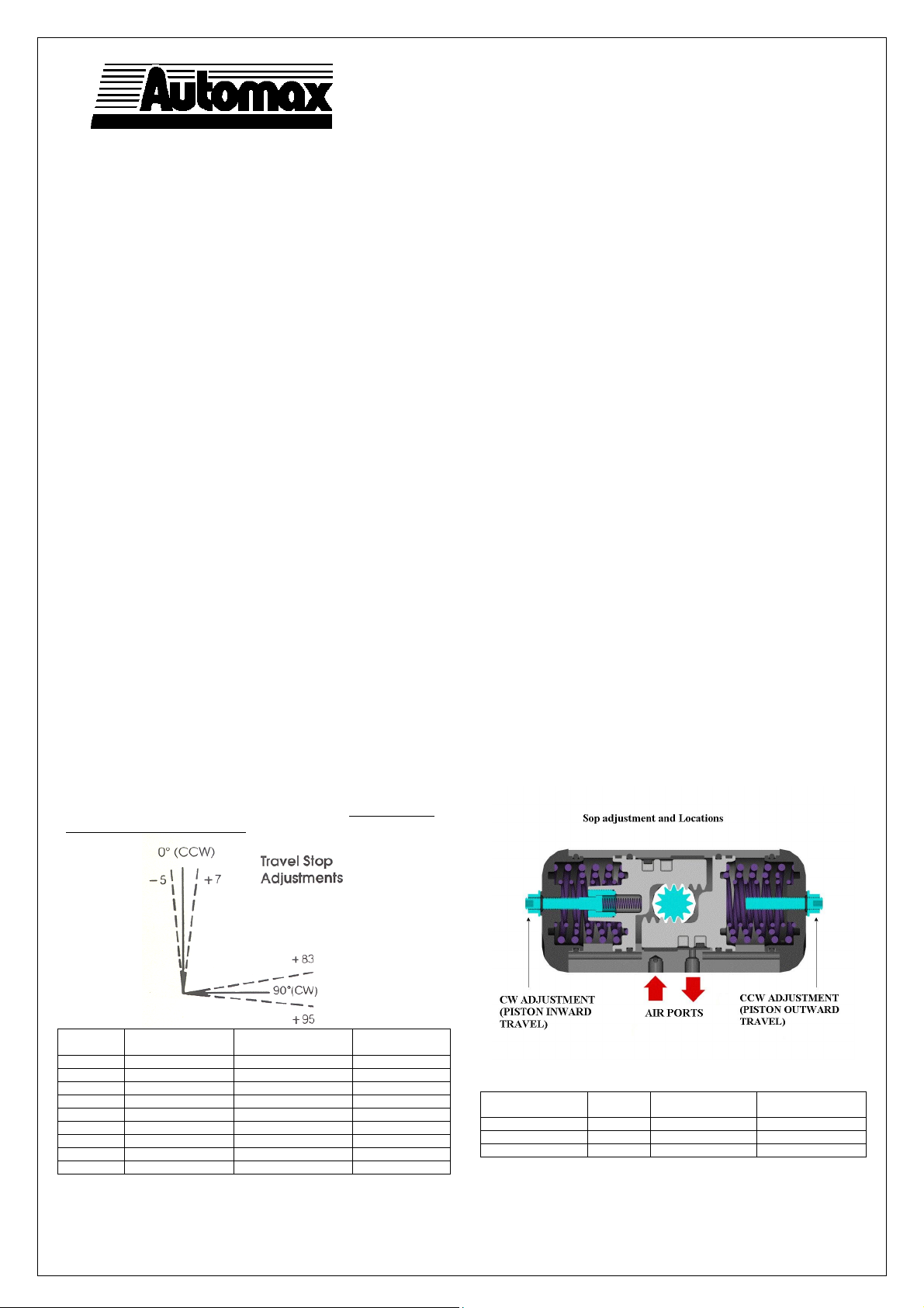
Travel Stop Adjustment
Both Directions 5° Overtravel
12°Adjustment Each End
The SuperNova Series actuators have unique
travel stop adjustments in both clockwise and
counterclockwise directions. The 10° total overtravel
provides adjustments from –5° to +7° at the “0°”
Counterclockwise position and from +83° to + 95° at the
“90°” Clockwise position.
All actuated valves require accurate travel-stop
adjustments at both ends of the stroke to obtain optimum
performance and valve seat life. The accumulation of
tolerances in the adaption of the actuators to valves is such
that there must be a range of adjustment for both ends of
the stroke to achieve the expected performance.
Ball and Plug Valves require precise adjustment at the
open (CCW) position to protect the seat from the flow
media and the closed (CW) position to assure absolute
shut-off
Butterfly Valves require precise adjustment at the closed
position to assure full shut-off, to prevent disc overtravel
and damage to the seat at the closed position.
Tandem Valves, where two valves are operated in tandem
through a single solenoid valve (eg. A 3-Way
configuration), absolutely require precise adjustment at
both ends of the stroke to assure the seating of both
valves.
Actuator Endcap Screw
Socket Size
S050 4 mm 3 mm White
S063 5 mm 4 mm Light green
S085 6 mm 5 mm Blue
S100 6 mm 6 mm Red
S115 6 mm 6 mm Yellow
S125 8 mm 6 mm Grey
S150 8 mm 8 mm Dark green
S175 10 mm 8 mm Purple
S200 12 mm 8 mm Orange
Adjustment Bolt
Socket Size
Spring Color
Code
Actuator Type Fail
position
Double Acting Left End Cap Right End Cap
Spring Return CW Left End Cap Right End Cap
Spring Return* CCW* Right End Cap Left End Cap
*The pistons are rotated 180° for CCW fail position
Clockwise (CW)
closed
Counterclockwise
(CCW) open
Adjustment Bolt Location
Page 2
SuperNova Series
S050 - S200
Rack & Pinion AUTOMAX Actuators
Page 2/4
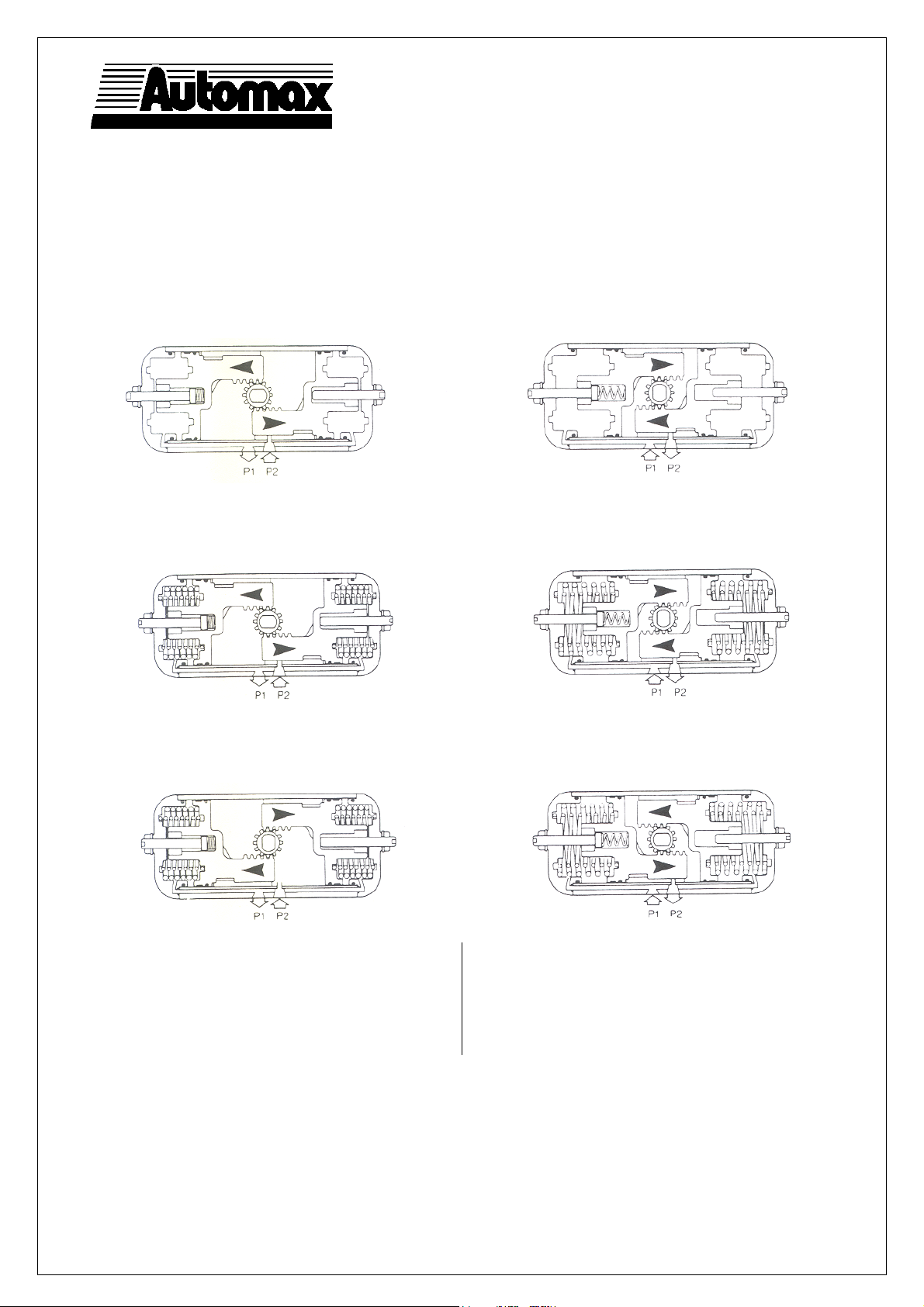
OPERATION
(As viewed from top of the actuator)
Double Acting
Applying air pressure to Port 2 drives the pistons outward,
which turns the pinion counterclockwise as the air volume on
the outside of the pistons exhausts through Port 1.
Applying air pressure to Port 1 drives the pistons inward,
which turns the pinion clockwise as the air volume on the
inside of the pistons exhausts through Port 2.
B00043e4-rev3.doc
Spring return (Fail CW)
Applying air pressure to Port 2 drives the pistons outward,
which compresses the springs and turns the pinion
counterclockwise as the air volume on the outside of the
pistons exhausts through Port 1.
Spring Return (Fail CCW)
Applying air pressure to Port 2 drives the pistons outward,
which compresses the springs and turns the pinion
clockwise as the air volume on the outside of the pistons
exhausts through Port 1.
Changing direction of pinion rotation (CW to CCW)
The SuperNova series actuators are normally assembled
as Double Acting or Spring Return Fail CW (spring action
turns pinion clockwise).
To assembly the actuator on Spring Return Fail CCW
(spring action turns pinion counterclockwise):
1. Follow disassembly procedures (next page) from
point #1 through #8.
Exhausting the air pressure from Port 2 allows stored energy
of the springs to drive pistons inward, turning the pinion
clockwise. Air volume on outside of pistons vents through
Port 1.
Exhausting the air pressure from port P2 allows stored
energy of the spring to drive pistons inward, turning the
pinion counterclockwise. Air volume on outside of pistons
vents through Port 1.
2. Rotate both pistons 180° around their axis: left
piston rack must be on air supply ports side, right
pinion on the opposite side (see Spring Return
CCW drawing).
3. Follow reassembly procedures.
Page 3
SuperNova Series
S050 − S200
Rack & Pinion AUTOMAX Actuators
Page
MAINTENANCE INSTRUCTIONS
Disassembly Procedures
1. Disconnect all air and electrical supplies from actuator.
2. Remove all accessories from actuator and dismount
actuator from valve.
3. Position actuator with air supply ports facing you. Apply
air pressure to Port 2 to release spring pressure from the
Stop Bolt (9).
4. Remove the Stop Bolt Retaining Nut (14), Washer (15),
and O-ring (16) on the left Endcap (19) and turn the Stop
Bolt (9) clockwise into the Body (1) until it is flush with
the Endcap (19).
5. Exhaust air from Port 2, the Stop Bolt (9) should now
turn freely. Continue turning Stop Bolt (9) clockwise until
it is disengaged from the Endcap.
6. S Spring Return Actuator:
CAUTION: Follow step 4 to relieve force on inward travel
stop before proceeding.
To remove S Endcaps, first completely remove two
diagonal Endcap Screws (21) from one Endcap. The two
remaining Encap Screws should be removed evenly. As
the screws are removed, the springs will push the
Endcap out. Repeat for opposite side. The springs well
be totally unloaded before the screws are completely
unthreaded.
Remove the springs (23, 24, 25).
Spring return version
D Double Acting Actuator:
Remove the 8 Endcap Screws (21). Step 7 will push the
Endcaps (18, 19) from the Body (1).
7. Rotate Pinion (3) counterclockwise (D & S-FCW) or
clockwise (D & S-FCCW) to drive the Pistons (2) off the
end of the rack. Pull the Left Piston (2) from the body (1)
by pulling on the Stop Bolt (9).
8. Remove the Right Piston (2a) by pushing out through
inside of Body (1).
9. Remove the Snap Ring (5) Steel Pinion Washer (4a) and
Pinion Washer (4).
10. Tap Pinion (3) lightly with plastic mallet to remove.
11. Remove seals from pinion, endcaps, and piston. If
necessary, remove seal from top pinion bearing.
12. Top pinion bearing (26) is a light press fit into the
housing. To remove, press out towards the bottom of the
actuator body. Take care not to damage any of the
surfaces. Bottom pinion bearing (27) is split. To remove,
find split in bearing and spread apart just enough to fit
over bottom pinion.
Reassembly Procedures
1. Inspect all parts for wear and replace any worn parts as
needed. Replace all O-rings.
2. Clean all components and lightly grease cylinder bore,
pinion and seals with a multi-purpose “polymer” fortified
grease such as DuBois Chemicals MPG-2.
3. Reverse the disassembly procedures to reassemble.
4. If top pinion bearing (26) was removed, it must be
pressed back into place. The top edge of the bearing
must be even with the top of the body. Insert top pinion
bearing seal (28) into place, pressing down with a blunt
screwdriver or similar tool, taking acre not to damage the
seals.
5. The standard Pinion (3) orientation is with the top
accessory drive slot at 90° to the Body (1) in the 0°
position.
6. When fitting the Pistons (2 and 2a) ensure the teeth
engage the Pinion (3) at the same time by measuring in
from each end. Note: the orientation of the pistons will
determine the operation of the actuator. Refer to the
diagrams under “Operation” for correct piston position.
7. Test the actuator for smooth operation and air leakage at
service pressure before reinstalling.
Changing Number of Springs
1. Follow the Disassembly Procedures through step 6
2. Determine nested spring combination of inner, middle
and outer spring. Consult catalog torque charts. Insert
appropriate spring according to the attached chart into
cylinder. Springs must be properly seated against
piston and endcap to assure that springs do not bind.
3. Re-assemble the actuator.
Spring chart models 63-200
Spring
Group
S04
S05
S06
S07
S08
S09
S10
S11
S12
Spring chart model 50
Spring
Group
S04
S05
S06
S07
S08
S09
Notes: #1 Spring has one color code dot
#2 Spring has two color code dots
#3 Spring has three color code dots
S050 has maximum of 2 springs per endcap
Spring Combination 1
#1 Spring
(inner)
- 2 -
- 1 1 3 bar
- - 2
1 - 2 4 bar
2 - 2 5 bar
1 1 2
- 2 2 5,5 bar
1 2 2
2 2 2
#1 Spring
(inner)
1 1 -
- 2 - 3 bar
2 1 - 4 bar
1 2 - 5 bar
2 2 - 5,5 bar
2 - 2
#2 Spring
(middle)
Spring Combination 1
#2 Spring
(middle)
B00043e4-rev3.doc
#3 Spring
(outer)
#3 Spring
(outer)
3/4
Standard
Configuration
(Air Supply)
Standard
Configuration
(Air Supply)
Page 4

SuperNova Series
S050 - S200
Rack & Pinion AUTOMAX Actuators
Page 4/4
PARTS & MATERIALS
B00043e4-rev3.doc
ITEM
DESCRIPTION STANDARD MATERIAL Quantity
No.
D S
1
Body Hard Anodized Aluminium 1 1
2
Left Piston Die Cast Aluminium 1 1
2a
Right Piston Die Cast Aluminium 1 1
3
Pinion Nitride Coated Steel 1 1
4*
Pinion Washer Nylon 1 1
4a*
Steel Pinion Washer Stainless Steel 1 1
5*
Pinion Snap Ring Steel/Plated 1 1
6*
Upper pinion O-ring Nitrile Rubber 1 1
7*
Lower pinion O-ring Nitrile Rubber 1 1
8*
Piston and end cap O-ring Nitrile Rubber 4 4
9
10
11
12*
13*
14
15
16*
17
18
19
20*
21
22
23
24
25
26*
27*
28*
Inward travel stop bolt Stainless Steel
Inward travel retaining nut Stainless Steel
Inward travel spring Steel/Plated 1 1
Piston guide Nylon and Molybdenum Disulfide 2 2
Piston guide band Nylon and Molybdenum Disulfide 2 2
Stop bolt retaining nut Stainless Steel 2 2
Stop bolt washer Stainless Steel 2 2
Stop bolt O-ring Nitrile Rubber 2 2
Stop bolt Stainless Steel 1 1
Right end cap Die Cast Aluminium/Electrostatic Poly 1 1
Left end cap Die Cast Aluminium/Electrostatic Poly 1 1
End cap supply O-ring Nitrile Rubber 2 2
End cap screw Stainless Steel 8 8
Anti ejection device (optional) Nylon 2 2
Outer spring Spring Steel Coated 0 2 max
Middle spring Spring Steel Coated 0 2 max
Inner spring Spring Steel Coated 0 2 max
Top pinion bearing Hard Anodized Aluminium 1 1
Bottom pinion bearing PEEK 1 1
Top bearing O-ring Nitrile Rubber 1 1
1 1
1 1
NOTES:
D= double acting actuators
S= spring return actuators
* parts included in a Repair Kit
SEALS:
Standard - Nitrile:
-30°C ÷ +80°C (-20°F ÷ +175°F)
H= High temp. – Viton:
-30°C ÷ +150°C (-22°F ÷ +302°F)
L= Low temp. – Fluorosilicon:
-50°C ÷ +80°C (-58°F ÷ + 176°F)
PRESSURE RATING:
10 bar (150 psi) max
Flowserve Flow Control (UK) Ltd.
Burrell Road, Haywards Heath
West Sussex RH16 1TL
United Kingdom
Tel. +44 (0)1444 314400
Fax +44 (0)1444 314401
E-mail:ukfcinfo@flowserve.com
http://www.flowserve.com
 Loading...