

Page 1
USER INSTRUCTIONS
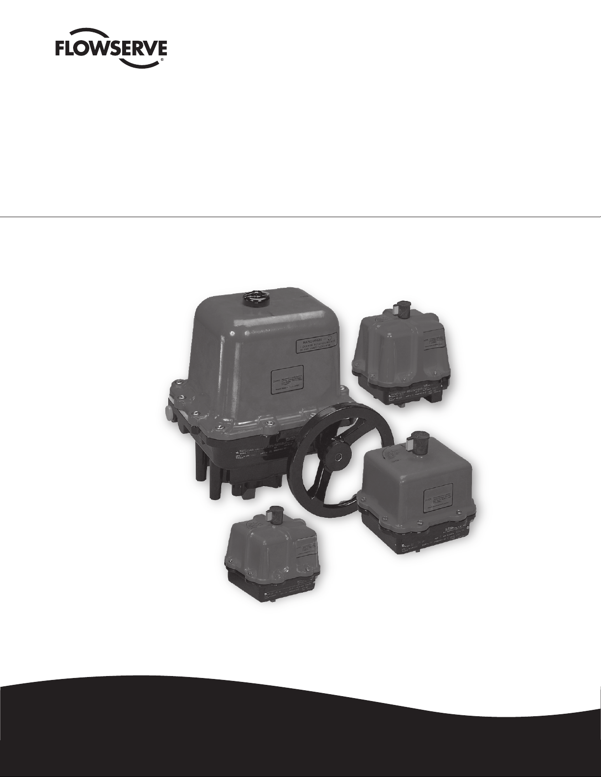
L75 Series Electric Actuator
Modbus RTU Electronic Positioner
FCD LMAIM7502-00 – 07/05
Installation
Operation
Maintenance
Experience In Motion
Page 2

Page 3

L75 Series Electric Actuator — Modbus RTU FCD LMAIM7502-00 – 07/05
Contents
Introduction 4
Principles of Operation 4
General Environmental Information 4
Mechanical Installation 5
Electrical Connections 5
Adjustment of Switch Cams 7
Board Indicators 7
Termination Resistors 7
Configuration 8
Modbus Address Selection 8
Baud Rate Selection 8
Two-Wire or Four-Wire Bus Selection 8
Modbus Functions 8
Modbus RTU Message Format 9
Reception of Invalid Commands 13
Reception of Commands with Illegal Fields 14
Modbus Exception Responses 14
Troubleshooting 15
flowserve.com
3
Page 4

L75 Series Electric Actuator — Modbus RTU FCD LMAIM7502-00 – 07/05
Introduction
The Modbus RTU electronic positioner utilizes the RTU (Remote Terminal Unit) transmission mode to
communicate on standard Modbus networks. The mode and other serial parameters (baud, parity, stop
bits, etc.) must be configured the same for all devices on a Modbus network.
Principles of Operation
The Flowserve Modbus RTU Interface Card is a valve automation and control product that uses the
Modbus communication protocol to operate and monitor position as well as provide predictive and
preventative maintenance functions.
When power is first applied to the board, the motor drive circuits are inactive and the valve will remain
in its current position. A valve position is maintained until a Modbus movement command is received.
Modbus functions are viewed as commands and are available to start or stop movement in a particular
direction, to read the status of the end-of-travel limit switches, and to read the status of the motor drive
circuits. If all three indicator LEDs blink simultaneously when power is first applied, the Modbus address
is not correct and the actuator will not operate. Refer to Modbus Address Selection in the Configuration
section to correct the problem.
Using a Modbus command, the valve shaft can be rotated either clockwise (CW) or counterclockwise
(CCW). A movement command will cause rotation in a specified direction. Valve movement will continue
until either the end-of-travel limit switch opens, or a stop command is received. In full open/close applications, the stop command is not needed. In other applications, the valve can be stopped in mid-travel
by issuing a stop command before the end-of-travel limit switch opens.
It is not possible to command movement in both CW and CCW directions simultaneously. If this is
attempted, the last positioning command will remain in effect. If a command is issued to move in a
direction opposite to the current direction of movement, the actuator will stop movement in the current
direction, delay for one second, and then begin moving in the specified direction (i.e. a stop command
is not needed to change directions).
General Environmental Information
The L75 Modbus RTU Electronic Positioner is sensitive to electrical noise on communication and power
supply lines. The positioner can also be affected by radiated electrical noise. For best positioner operation, the electrical noise level should be as low as possible. Follow the wiring guidelines in this manual
carefully.
Shielded, twisted-pair wire is recommended for the communication cable. If shielded, twisted-pair wire
is not available, non-shielded twisted pair cable is the next best alternative to prevent susceptibility to
electrical noise. Unshielded, non-twisted cable is not recommended.
4
Page 5

L75 Series Electric Actuator — Modbus RTU FCD LMAIM7502-00 – 07/05
Flowserve recommends an indoor storage environment suitable for human occupancy if the product
must be stored prior to installation. Do not store the positioner in any of the following conditions:
Where exposure to relative humidity is greater than 85%.
1.
Where acid or alkali fumes are present.
2.
Where ultraviolet or other radiation is above normal background conditions.
3.
Where temperatures are above 120°C or are below -40°C
4.
Within 50 feet of any source of ozone.
5.
Operating solid-state electronic equipment near or beyond its high temperature ratings is the primary
cause for most failures. It is very important to consider factors that affect this product’s operating
temperature. Operating an electronic device at or below its low temperature rating may result in
inoperability. Proper operation usually resumes when rated operating temperatures are established.
Low-temperature problems can be easily cured by addition of a thermostatically controlled heater to the
actuator housing.
Flowserve has manufactured this product using moisture-proofing and fungicidal coatings. The coatings
provide added protection against the affects of high humidity. Where relative humidity is consistently
80% to 90% and the ambient temperature is subject to large variations, a heater/thermostat option
should be installed in the actuator housing. The heater should not increase the internal temperature
beyond the rated operating temperature.
Table 1: Electronic Printed Circuit Board Specifications
Power requirements
8345 / 8354 Modbus RTU Interface Card 120 VAC – 50 mA max.
8336 / 8366 Modbus RTU Interface Card 240 VAC – 25 mA max
Device Modbus
Firmware Revision 5/6/00
Transmission Speed 9.6 or 19.2 Kbaud maximum
Temperature
Operational -40°F to 150°F (-40°C to 65°C)
Storage -40°F to 250°F (-40°C to 120°C)
Mechanical Installation
Installation is best performed at the factory using brackets and mounting hardware designed for
the purpose. Factory-trained individuals must perform installation and calibration in any event. Field
upgrade of a non-Modbus unit to Modbus unit is possible with the proper hardware and training.
Electrical Connections
CAUTION: To prevent ignition of hazardous atmospheres, keep cover bolts tight while circuits
a
are live. Disconnect supply circuit before opening.
Entry into the actuator housing is made through one of the NPT conduit entries. Electrical data connections are made to a captive screw cage terminal strip located on the Modbus RTU board. Electrical
power (120 VAC) and limit switch connections are made to the actuator terminal strip.
5
flowserve.com
Page 6

PCB
REDBLK
J2 J1
W8
BLK
W8
BLK
W9
RED
RED
W9
VIEW SHOWING J1,J2 WIRES
FOR 240VAC USAGE
RESISTOR
USAGE
R22,R24
R22,R23,R24,R25
R22,R24
R22,R23,R24,R25
240VAC
25/30
NO YES
240VAC
10/23
NO YES
115VAC
25/30
YES NO
NOYES
10/23
115VAC
08366
08336
08354
08345
WIRES
W8 & W9
JUMPERS
J1 & J2
SIZE
ACTUATOR
PART NO.
VOLTAGE
INPUT
CAUTION:
BOARD
BEFORE REPLACING
REMOVE POWER
PROTECTIVE COVER
DO NOT REMOVE
HIGH VOLTAGE
CAUTION:
(W5) RED
(W6) GRA
(W7) ORN
SW1
LD2
LD1
TP1
SW2
LD4LD3 LD5
T1
GRA
2
BRN
4
BLK RED
3
CCW C
RED
WHT
1
J1
REDBLK
J2
CCW
CW
MSD
A
485 BUS TO MODBUS
SHLD
CCW
W/BORN
Z Y B
TB1
4W
2-WIRE OPERATION
2W
JUMPER 2W FOR
4W
2W
GND
SEL BAUD RATE
COMMSW3SW4
9600
19.2K
NODE ADDRESS
LSD
(W4) BLK
(W3) RED
(W2) BRN
(W1) WHT
XXXXX
PART NUMBER LABEL PER
LISTING IN SHEET 3 TABLE
L75 Series Electric Actuator — Modbus RTU FCD LMAIM7502-00 – 07/05
CAUTION: Be sure to observe correct polarity of the power connections or damage to the
a
printed circuit board will occur!
Figure 1: Modbus RTU Board
6
Page 7

L75 Series Electric Actuator — Modbus RTU FCD LMAIM7502-00 – 07/05
Adjustment of Switch Cams
1. Loosen captive cover screws and remove lid, turning slightly while lifting.
2. Place the actuator in the CW position and apply voltage to the Modbus RTU Interface Card.
3. Loosen the CW cam set screw.
4. Adjust the cam associated CW limit switch clockwise until the CW LED is illuminated.
5. Tighten the cam set screw for the CW cam.
6. Place the actuator in the CCW position.
7. Loosen the CCW cam set screw.
8. Adjust the cam associated CCW limit switch rotate counter-clockwise until the CCW LED is
illuminated.
9. Tighten the cam set screw for the CCW cam.
10. Cycle the actuator to insure that each LED is illuminated at the appropriate time. Some minor
readjustment might be necessary.
11. Clean base, lid flanges, and replace lid on base.
NOTE: Make sure wires are not caught between flanges
12. Tighten captive screws.
Board Indicators
The Modbus RTU Interface Board contains several LED indicators that are helpful when initially configuring the device or when troubleshooting. Refer to figure one for the locations of the indicators.
CW The CW LED illuminates to indicate motor circuits are being driven to cause movement in the
CW direction. The LED will stay on during valve movement and will remain on until a stop movement
command is received.
CCW The CCW LED illuminates to indicate motor circuits are being driven to cause movement in the
CCW direction. The LED will stay on during valve movement and will remain on until a stop movement
command is received.
SW3 The SW3 LED illuminates when the CW limit switch is activated (closed) with the valve in the full
CW position.
SW4 The SW4 LED illuminates when the CCW limit switch is activated (closed) with the valve in the
full CCW position.
COMM The COMM LED illuminates whenever the actuator is receiving or transmitting a message. The
COMM LED will blink when any message is received - even if the message is for another actuator.
Termination Resistors
Termination resistors are not required at master or slave units.
7
flowserve.com
Page 8

L75 Series Electric Actuator — Modbus RTU FCD LMAIM7502-00 – 07/05
0
F
E
D
C
B
A
9
8
7
6
5
4
3
2
1
0
F
E
D
C
B
A
9
8
7
6
5
4
3
2
1
MSD
Configuration
The data link layer of communication conforms to the Modbus RTU specification. Slaves (actuators)
reply on the bus only in response to a valid command from the master control unit addressed to the
actuator. Each actuator has an address selected with switches on the actuator board. An actuator can
have any address from 1 to 247. (Modbus address 0 is reserved for broadcast messages). The address
is specified using two hexadecimal rotary switches. If an illegal address is set in the switches, the
actuator will not respond to any commands.
Modbus Address Selection
The Modbus address may be between 1 and 247 (decimal) or 01 and F7 hexadecimal. Address 0 is used
for broadcast messages only. Two on-board, rotary hexadecimal switches are used to set the address.
Remember the addresses on the switch must be specified in hexadecimal—not decimal. Be sure the
address is correctly set on the switches. If an invalid address is set, the SW3, SW4 and COMM LEDs
will blink simultaneously and the unit will not be operational.
Figure 2: Node Address
Baud Rate Selection
Communication data rate is jumper-selectable as either 9600 bits per second or 19,200 bits per second.
Other communication parameters are fixed at no parity, 8 data bits, and 1 stop bit. Set the baud rate by
positioning the jumper as required for the appropriate transmission rate.
Two-Wire or Four-Wire Bus Selection
The RS-485 Modbus bus can be set to operate in either a two-wire or four-wire configuration. Set the
on-board jumpers as required for the desired configuration. Be sure that both jumpers are set for the
desired configuration. In either case, termination resistors are not required at segment ends.
Modbus Functions
The actuator supports the Modbus RTU protocol only. The actuator supports the following Modbus
functions:
Function Code Function Name Description
1 Read coil status State of motion control
2 Read input status State of limit switches
3 Read holding register State of actuator operation
8
5 Force single coil Starts/Stops actuator
6 Preset single register Starts/Stops actuator
Page 9

L75 Series Electric Actuator — Modbus RTU FCD LMAIM7502-00 – 07/05
Modbus functions are seen as commands to the positioner. Hereafter in this manual, they will be called
commands. A summary of commands to cause specific valve movement are shown in the table below:
Action Modbus Function (code) Coil/Reg. # (address) Data
CW Force single coil (05) Coil 1 (0000H) FF00 (hex)
Stop CW Force single coil (05) Coil 1 (0000H) 0000 (hex)
CCW Force single coil (05) Coil 2 (0001H) FF00 (hex)
Stop CCW Force single coil (05) Coil 2 (0001H) 0000 (hex)
CW Preset single reg. (06) Register 40,001 256 (dec)
Stop Preset single reg. (06) Register 40,001 512 (dec)
CCW Preset single reg. (06) Register 40,001 768 (dec)
Modbus RTU Message Format
Field Name Example
Actuator Address 05 (actuator 45)
Function 01 (Read Coil Status)
Starting Address (High) 00
Starting Address (Low) 00 (coil 1)
Number of Points (High) 00
Number of Points (Low) 01 (return 1 status)
CRC Error Check (LS byte) FC
CRC Error Check (MS byte) 4E
NOTE: The least significant byte of the 16-bit CRC value is sent first before the most significant byte.
Each message consists of the bytes mentioned above sent consecutively with less than a 1-½-character
time gap between bytes. Messages are considered completed when the actuator sees a time gap greater
than 1-½ characters.
Read Coil Status Command (01)
This command reads the ON or OFF state of the specified coil (i.e. motion control circuit). Coil 1
represents the CW motion control circuit; coil 2 represents the CCW motion control circuit. The Modbus
message can have a starting address of 0 or 1 (for coil 1 or 2, respectively). The number of points can
be either 1 or 2 when coil 1 is specified and should be 1 if coil 2 is specified. Requesting more than
2 points with coil 1 or more than 1 point with coil 2 will result in an error response. Regardless the
number of points requested, only one data byte will be returned. Broadcast is not supported.
Example: “Read the status of the CW motion control circuit (coil 1) on actuator #5”
Field Name Example
Actuator Address 05
Function (Read Coil Status) 01
Starting Address (High) 00
Starting Address (Low) 00
Number of Points (High) 00
Number of Points (Low) 01
CRC Error Check (LS byte) FC
CRC Error Check (MS byte) 4E
9
The bytes sent (in hex) to the actuator in the above example would be: 05, 01, 00, 00, 00, 01, FC, 4E
flowserve.com
Page 10

L75 Series Electric Actuator — Modbus RTU FCD LMAIM7502-00 – 07/05
Response to a Read Coil Status Command
A response to a correct reception of the command would have the data field set to either 00 (not driving
in the specified direction) or 01 (actively driving in the specified direction). The example response below
shows the CW motion control circuit is actively driving the valve in the CW direction.
Field Name Example
Actuator Address 05
Function (Read Coil Status) 01
Byte Count 01
Data 01
CRC Error Check (LS byte) 91
CRC Error Check (MS byte) 78
The bytes sent (in hex) to the master in the above example would be: 05,01,01,01.91,78
If coil 1 (CW) is specified and 2 points are requested, the data is packed into one byte of data where coil
1 (CW) status is bit 0 and coil 2 (CCW) status is bit 1 of the byte. If coil 2 (CCW) status is requested,
only one point can be specified and is returned in bit 0.
Data Byte When 2 Coil Statuses are Read
7 6 5 4 3 2 1 0 Status
0 0 0 0 0 0 0 0 Valve is not being driven in either direction.
0 0 0 0 0 0 0 1 Valve is being driven in the CW direction.
0 0 0 0 0 0 1 0 Valve is being driven in the CCW direction.
0 0 0 0 0 0 1 1 This status value is not possible.
10
Read Input Status Command (02)
This command reads the state of one or both end-of-travel limit switches. The CW limit switch detects
end-of-travel in the clockwise direction and is at register location 10001; the CCW limit switch detects
end-of-travel in the counterclockwise direction and is at register location 10002. Both locations can be
requested by reading two register locations starting at location 10001 or the locations can be requested
separately. Broadcast is not supported.
Example: “Read the status of both limit switches on actuator #5”
Field Name Example
Actuator Address 05
Function (Read Input Status) 02
Starting Address (High) 00
Starting Address (Low) 00
Number of Points (High) 00
Number of Points (Low) 02
CRC Error Check (LS byte) F8
CRC Error Check (MS byte) 4F
The bytes sent (in hex) to the actuator in the above example would be: 05, 02, 00, 00, 00, 02, F8, 4F
Page 11

L75 Series Electric Actuator — Modbus RTU FCD LMAIM7502-00 – 07/05
Response to a Read Input Status Command
Because two points were requested, bit 0 in the data field is the state of the CCW limit switch and bit 1
is the state of the CW limit switch (see the table below). For either bit, a 1 means the switch is activated
(closed) and a 0 means the switch is deactivated (open). In the example below, only the CW limit switch
is activated.
Field Name Example
Actuator Address Returned 05
Function (Read Input Status) 02
Byte Count 01
Data 02
CRC Error Check (LS byte) 21
CRC Error Check (MS byte) 79
The bytes returned (in hex) to the master in the above example would be: 05, 02, 01, 02, 21, 79
Data Byte When Two Limit Switch Statuses are Read
7 6 5 4 3 2 1 0 status
0 0 Both CW and CCW limit switches are OFF
0 1 CCW limit switch is ON, CW limit switch is OFF
1 0 CW limit switch is ON, CCW limit switch is OFF
1 1 If the actuator has been properly calibrated, this
state will never be returned since both switches
should not be on at the same time.
Read Holding Register Command (03)
This command reads the state of both end-of-travel limit switches, as well as actuator motion. The CW
limit switch detects end-of-travel in the clockwise direction and is at register location 40,009 (bit 0) and
40,012 (bit 5); the CCW limit switch detects end-of-travel in the counterclockwise direction and is at
register location 40,009 (bit 1) or 40,012 (bit 3); the stopped motion holding register is 40,009 (bit 2);
the CW motion holding register is 40,009 (bit 3); the CCW motion holding register is 40,009 (bit 4). All
register bit locations must be requested simultaneously by reading each register entirely. Broadcast is
not supported.
Example: “Read holding register 40, 012 for CW and CCW limit switch statuses of actuator #1”
Field Name Example
Actuator Address 01
Function (Read Coil Status) 03
Starting Address (High) 00
Starting Address (Low) 0B
Number of Points (High) 00
Number of Points (Low) 01
CRC Error Check (LS byte) F5
CRC Error Check (MS byte) C8
The bytes sent (in hex) to the actuator in the above example would be: 01, 03, 00, 0B, 00, 01, F5, C8
11
flowserve.com
Page 12

L75 Series Electric Actuator — Modbus RTU FCD LMAIM7502-00 – 07/05
Response to a Read Holding Register Command
Because 1 register was requested, bit 3 in the data field is the state of the CCW limit switch and bit 5 is
the state of the CW limit switch. For either bit, a 1 means the switch is activated (closed) and a 0 means
the switch is de-activated (open). In the example below, the low data byte is read as 00001000 since
only the CCW limit switch is activated.
Field Name Example
Actuator Address Returned 01
Function (Read Input Status) 03
Byte Count 02
Data Hi 00
Data Lo 08
CRC Error Check (LS byte) B9
CRC Error Check (MS byte) 82
The bytes returned (in hex) to the master in the above example would be: 01, 03, 02, 00, 08, B9, 82
Force Single Coil Command (05)
12
This command sets the state of a specific motion control circuit. Coil 1 is the CW motion control
circuit; coil 2 is the CCW motion control circuit. A force data of FF00 will either start or continue valve
movement; a force data of 0000 will stop valve movement. Other data values will return an exception
response. Only coil 1 and coil 2 are supported. Broadcast is not supported.
Example: “Direct actuator #5 to travel in the CW direction”
Field Name Example
Actuator Address 05
Function (Force Single Coil) 05
Coil Address (High) 00
Coil Address (Low) 00
Force Data (High) FF
Force Data (Low) 00
CRC Error Check (LS byte) 8D
CRC Error Check (MS byte) BE
The bytes sent (in hex) to the actuator in the above example would be: 05, 05, 00, 00, FF, 00, 8D, BE
Response to a Force Single Coil Command
The normal response is an echo of the original command, returned after the coil has been forced.
Field Name Example
Actuator Address 05
Function (Force Single Coil) 05
Coil Address (High) 00
Coil Address (Low) 00
Force Data (High) FF
Force Data (Low) 00
CRC Error Check (LS byte) 8D
CRC Error Check (MS byte) BE
The bytes sent (in hex) back to the master in the above example would be: 05, 05, 00, 00, FF, 00, 8D, BE
Page 13

L75 Series Electric Actuator — Modbus RTU FCD LMAIM7502-00 – 07/05
Preset Single Register Command (06)
This command sets the state of a specific motion control circuit by writing values to register 40,001.
By writing a value of 256 (dec) to the register, the CCW motion control circuit is activated. By writing a
value of 512 (dec) to the register, both the CCW and CW motion control circuits are deactivated. Finally,
writing a value of 768 (dec) to register 40,001 initiates the CW motion control circuit. Other data values
will return an exception response. Broadcast is not supported.
Example: “Direct actuator #1 to stop operation in either the CW or CCW direction”
Field Name Example
Actuator Address 01
Function (Force Single Coil) 06
Coil Address (High) 00
Coil Address (Low) 00
Force Data (High) 02
Force Data (Low) 00
CRC Error Check (LS byte) 88
CRC Error Check (MS byte) AA
The bytes sent (in hex) to the actuator in the above example would be: 01, 06, 00, 00, 02, 00, 88, AA
Response to a Preset Single Register Command
The normal response is an echo of the original command, returned after the register value is written.
Field Name Example
Actuator Address 01
Function (Force Single Coil) 06
Coil Address (High) 00
Coil Address (Low) 00
Force Data (High) 02
Force Data (Low) 00
CRC Error Check (LS byte) 88
CRC Error Check (MS byte) AA
The bytes sent (in hex) back to the master in the above example would be: 01, 06, 00, 00, 02, 00, 88, AA
Reception of Invalid Commands
A Modbus command is considered invalid if any of the following conditions is true:
The computed CRC value does not match the CRC in the received message.
1.
The message is not addressed to the actuator.
2.
The message is a broadcast message.
3.
In any of the above situations, the actuator will discard the invalid message and no error response will
be returned. The master should detect a timeout and reissue the command.
Reception of Commands with Illegal Fields
If a command is received with a field containing an illegal value, the actuator will reply with an Exception
Response (see the Modbus Exception Responses section below). No exception response will be given if
13
flowserve.com
Page 14

L75 Series Electric Actuator — Modbus RTU FCD LMAIM7502-00 – 07/05
the message was broadcast—the command will not be executed. A command contains an illegal field if
any of the following conditions is true:
The message contains a coil address other than 1 or 2.
1.
The message contains a register address other than locations 10001 (coil 1) or 10002 (coil 2).
2.
The message contains force coil data other than 0000 or FF00 hex.
3.
The message contains an incorrect number of points.
4.
The message contains an unimplemented function code.
5.
The message contains a read holding register address other than 40,004 – 40,013
6.
The message contains a register preset value other than 256, 512, or 768 (dec).
7.
Modbus Exception Responses
Exception responses are given when the actuator receives a command message with at least one field
containing an illegal value. In an exception response, the actuator returns the function code byte with
the most significant bit set followed by an exception code byte.
The following exception codes are supported:
Exception
Code
01 Illegal Function The function code received in the query is not supported by the actuator.
02 Illegal Data Address
03 Illegal Data Value
Name Meaning
The data address (register or coil address) received is not an allowable
address for the actuator.
A value contained in a data field that is not an allowable value for the
actuator. This could include the request of more data points than are allowed
or forced coil data of other than 0000 or FF00 hex.
An exception response message contains the address of the actuator, the function in error, an error code
from the table above and the CRC bytes. The Error Function is the function code byte with the most
significant bit set. The fields of an exception message are shown below:
Command issued by host:
Field Name Example
Actuator Address 05
Function (Read Coil Status) 01
Starting Address (High) 00
Starting Address (Low) 06 (Illegal Address)
Number of Points (High) 00
Number of Points (Low) 01
CRC Error Check (LS byte) 1C
CRC Error Check (MS byte) 4F
Response from the actuator:
Field Name Example
Actuator Address 05
Error Function (Read Coil Status) 81
Exception Code (Illegal Data Address) 02
CRC Error Check (LS byte) 80
CRC Error Check (MS byte) 50
14
Page 15

L75 Series Electric Actuator — Modbus RTU FCD LMAIM7502-00 – 07/05
Troubleshooting
The following troubleshooting guide is given to help determine causes of some common problems.
Symptom Things to Check
When power is applied, all three
indicator LEDs blink and the
actuator will not operate properly.
Actuator does not respond to
any Modbus commands. The
COMM LED does NOT blink when
commands are sent.
Actuator does not respond to any
Modbus commands. The COMM
LED blinks when commands are
sent. No exception response is
received.
The COMM LED blinks even when a
Modbus command is not sent.
The actuator accepts Modbus
commands, but does not move in a
specified direction.
The actuator responds with an
exception response.
After a movement command is sent,
the valve moves but a subsequent
status read does not indicate the
valve in the desired position.
The Modbus address is not correctly entered on the address
1
switches. Refer to Modbus Address Selection section to correct the
problem.
1 Be sure power is applied to the actuator.
2 Be sure the Modbus baud rate and wire configuration is correctly set.
Check that communications wires are correctly connected.
3
1 Check that the message is sent to the address of the actuator.
Ensure data cables are not located near sources of noise. Use
shielded, twisted-pair cable if possible.
2
Ensure data cables are not located near sources of noise. Use
1
shielded, twisted-pair cable if possible.
Check the actuator wiring to the motors. Check for loose or broken
1
wires.
If wiring appears intact, check the LED for the direction specified.
If it is ON after the command is issued, either the motor wire is
2
disconnected, or the actuator board needs replacing. If the LED is
OFF, replace the actuator board.
Read the error code received and determine the problem using the
1
Exception Responses table.
The valve may not be done moving when the read status command
1
is issued. Delay before reading the status to give the valve time to
move.
Ensure the limit switches are correctly set for the end-of-travel. See
2
the Installation Manual for details.
flowserve.com
15
Page 16

FCD LMAIM7502-00 Printed in USA.
To find your local Flowserve representative:
For more information about Flowserve Corporation, visit
www.flowserve.com or call USA 1 800 225 6989
United States
Flowserve Corporation
Flow Control
Limitorque Actuation Systems
5114 Woodall Road
P.O. Box 11318
Lynchburg, VA 24506-1318
Phone 434 528 4400
Fax 434 845 9736
United Kingdom
Limitorque
Abex Road
Newbury
Berkshire, RG14 5EY
England
Phone 44-1-635-46999
Fax 44-1-635-36034
Japan
Limitorque Nippon Gear Co., Ltd.
Asahi-Seimei Bldg. 4th Floor
1-11-11 Kita-Saiwai, Nishi-Ku
Yokohama-Shi, (220-0004)
Japan
Phone 81-45-326-2065
Fax 81-45-320-5962
India
Limitorque India, Ltd.
15/4, Mile Stone
Mathura Road
Faridabad - 121002
India
Phone 91-129-2276586, 2276836
Fax 91-129-2277135
Flowserve Corporation has established industry leadership in the design and manufacture of its products. When properly selected, this Flowserve product is designed to perform its intended
function safely during its useful life. However, the purchaser or user of Flowserve products should be aware that Flowserve products might be used in numerous applications under a wide
variety of industrial service conditions. Although Flowserve can (and often does) provide general guidelines, it cannot provide specific data and warnings for all possible applications. The purchaser/user must therefore assume the ultimate responsibility for the proper sizing and selection, installation, operation, and maintenance of Flowserve products. The purchaser/user should
read and understand the Installation Operation Maintenance (IOM) instructions included with the product, and train its employees and contractors in the safe use of Flowserve products in
connection with the specific application.
While the information and specifications contained in this literature are believed to be accurate, they are supplied for informative purposes only and should not be considered certified or as
a guarantee of satisfactory results by reliance thereon. Nothing contained herein is to be construed as a warranty or guarantee, express or implied, regarding any matter with respect to this
product. Because Flowserve is continually improving and upgrading its product design, the specifications, dimensions and information contained herein are subject to change without notice.
Should any question arise concerning these provisions, the purchaser/user should contact Flowserve Corporation at any one of its worldwide operations or offices.
© 2005 Flowserve Corporation, Irving, Texas, USA. Flowserve is a registered trademark of Flowserve Corporation.
flowserve.com
Australia
Flowserve Australia, Pty. Ltd.
14 Dalmore Drive
Scoresby, Victoria 3179
Australia
Phone 61 3 9759 3300
Fax 61 3 9759 3301
Singapore
Limitorque Asia, Pte., Ltd.
12, Tuas Avenue 20.
Singapore 638824
Phone 65-6868-4628
Fax 65-6862-4940
 Loading...