

Page 1
USER INSTRUCTIONS
Limitorque L120-85 Actuator
FCD LMENIM1202-00 – 11/05
Installation
Operation
Maintenance
Experience In Motion
Page 2

Limitorque L120-85 Installation, Operation and Maintenance FCD LMENIM1202-00 – 11/05
L120-85 Actuator
Installation and Maintenance Manual
©2005 Copyright Flowserve Corporation. All rights reserved.
Printed in the United States of America.
Disclaimer
No part of this book shall be reproduced, stored in a retrieval system, or transmitted by any means, electronic, mechanical, photocopying,
recording, or otherwise without the written permission from Flowserve. While every precaution has been taken in the preparation of the
book, the publisher assumes no responsibility for errors or omissions. Neither is any liability assumed for damages resulting from the use of
the information contained herein.
This document is proprietary information of Flowserve furnished for customer use ONLY. No other uses are authorized without written
permission of Flowserve.
Flowserve reserves the right to make changes, without notice, to this document and the products it describes. Flowserve shall not be liable
for technical or editorial errors or omissions made herein; nor for incidental or consequential damages resulting from the furnishing, performance or use of this document.
This manual contains information that is correct to the best of Flowserve’s knowledge. It is intended to be a guide and should not be considered as a sole source of technical instruction, replacing good technical judgment, since all possible situations cannot be anticipated. If there
is any doubt as to exact installation, configuration, and/or use, please contact Flowserve at 1-800-225-6989.
The choice of system components is the responsibility of the buyer, and how they are used cannot be the liability of Flowserve Corporation.
However, Flowserve’s sales team and application engineers are always available to assist you in making your decision.
Belden® is a registered trademark of Belden, a division of Cooper Industries, Inc.
2
Page 3

Contents
Limitorque L120-85 Installation, Operation and Maintenance FCD LMENIM1202-00 – 11/05
1.1 Purpose 5
1.2 User Safety
2.1 Product Identification
2.2 Product Description
2.3 Product Features
4.1 Safety 1
4.2 Initial Actuator Preparation 1
4.2.1 Inspection and Recording 1
4.2.2 Short-Term Storage (less than one year) 1
4.3 Actuator Mounting 1
4.3.1 Torque Only Applications (Drive 1) 1
4.3.2 Torque and Thrust Applications
4.3.3 Mounting Bolts 1
4.3.4 Stem Cover for Rising Stem Applications 1
4.4 Verifying Motor Rotation Direction 1
4.4.1 Initial Electrical Connections 1
4.4.2 Motor rotation (phasing)
and OPEN/CLOSE pushbutton operation. 15
4.4.3 Three-Phase Motor 1
4.4.4 DC Motor 1
4.5 Limit Switch Settings 1
4.5.1 Basic Theory of Operation 1
4.5.2 Adjustment—General 1
4.5.3 Setting the OPEN Limit Switch 1
4.5.4 Setting the CLOSE Limit Switch 1
4.6 Torque Switch Setting and Wiring 1
4.6.1 Basic Theory of Operation 1
4.6.2 Setting the Torque Switch 1
4.6.3 Balancing the Torque Switch 1
(Drive 2) 12
4.6.4 Rewiring the Torque Switch
5
4.7 Position Indication 2
7
8
8
1
5.1 Description of Motor Operation 2
1
5.2 Description of Manual Operation 2
1
6.1 Lubrication 2
1
2
2
3
3
8.1 Handwheel Shaft Assembly and Shimming 3
4
8.2 Verifying Handwheel Operation 3
4
8.3 Thrust Base Assembly and Shimming 3
9.1 Typical Wiring Diagram 3
5
10.1 L120-85 Illustrated Parts Breakdown 4
5
10.2 L120-85 Parts List 4
5
6
7
7
8
9
9
9
9
for Non-Standard Drive Sleeve Rotation 20
4.7.1 Local Position Indication 2
4.7.2 Remote Position Indication 2
4.7.3 Setting the Potentiometer 2
6.1.1 Initial Inspection 2
6.1.2 Frequency 2
6.1.3 Routine Inspection 2
6.1.4 Factory Lubricants 2
6.1.5 Minimum Lubricant Qualities Required 2
Three-phase with Control Package 3
0
0
1
2
3
3
5
5
5
5
5
6
1
3
3
7
7
0
5
flowserve.com
3
Page 4

Limitorque L120-85 Installation, Operation and Maintenance FCD LMENIM1202-00 – 11/05
Figures
Figure 1: Limitorque L120-85 Actuator 8
Figure 2: L120-85 Torque Drive Nut and Retaining Ring Details 1
Figure 3: Thrust Base removal from an L120-85 1
Figure 4: L120-85 Torque Drive Nut orientation (Drive 1) 1
Figure 5: L120-85 Thrust Base Assembly orientation (Drive 2) 1
Figure 6: Electrical Compartment and Conduit Pipe Plug openings 1
Figure 7: Grounding Lug location 1
Figure 8: Limit Switch Rotor development 1
Figure 9: L120-85 Limit Switch Components 1
Figure 10: Limit Switch OPEN/CLOSED Rotor Cam orientation 1
Figure 11: Torque Switch Components 1
Figure 12: Reversing Torque Switch wiring 2
Figure 13: Aligning MDPI Pointer for Fully CLOSED Position 2
Figure 14: Remote Position Indicator Calibration Configuration 2
Figure 15: Potentiometer Calibration configuration 2
Figure 16: Loosening Potentiometer Assembly 2
Figure 17: Removing Clutch Pinion Assembly 2
Figure 18: Key components affected by Handwheel shimming 3
Figure 19: Cut-away view of L120-85 actuator
with Clutch Latch positioned on face of Clutch Bearing 3
Figure 20: Gap between Housing face and Handwheel Bushing
shown as dimension “A” 3
Figure 21: Shimming parts and their order of assembly 3
Figure 22: Shim location for gap “B” dimension/ 3
Figure 23 Three-phase with Control Package 3
Figure 24: Electrical Compartment 4
Figure 25: Motor and Motor Drive Components 4
Figure 26: Handwheel Shaft and Associated Components 4
Figure 27: Drive Sleeve Group 4
Figure 28: Thrust Base Group 4
Tables
Table 1: L120-85 Approximate Weight Chart 9
2
Table 2: Torque Drive Nut: Maximum Allowable
Bore and Key Sizes 1
2
Table 3: L120-85 Actuator/Mounting Base Tap Size 1
3
Table 4: Gap “A” shim thickness selection chart 3
4
Table 5: Gap “B” shim thickness selection chart 3
4
5
6
7
8
9
0
0
1
2
2
9
1
2
2
3
3
7
0
1
2
3
4
2
3
2
3
4
Page 5

Limitorque L120-85 Installation, Operation and Maintenance FCD LMENIM1202-00 – 11/05
Introduction
1
1.1 Purpose
This Installation and Maintenance Manual explains how to install and
maintain the L120-85 actuator. Information is provided for installation, disassembly, reassembly, lubrication, and parts selection.
WARNING: Read this installation and maintenance man-
c
ual carefully and completely before storing, installing,
operating or troubleshooting your Flowserve Limitroque
actuator. Be aware of electrical hazards within the actuator and high-pressure hazards at the attached valve or
other device when installing or performing maintenance
on your L120-85 actuator.
1.2 User Safety
Safety notices in this manual detail precautions the user must take
to reduce the risk of personal injury and damage to the equipment.
The user must read and be familiar with these instructions before
attempting installation, operation, or maintenance. Failure to observe
these precautions could result in serious bodily injury, damage to the
equipment, voiding of the warranty, or operational difficulty.
Safety notices are presented in this manual in three forms:
WARNING: Refers to personal safety. Alerts the user to
c
potential danger. Failure to follow warning notices could
result in personal injury or death.
CAUTION: Directs the user’s attention to general precautions
a
that, if not followed, could result in personal injury and/or
equipment damage.
NOTE:
Highlights information critical to the user’s understanding of
the actuator’s installation and operation.
flowserve.com
5
Page 6

Limitorque L120-85 Installation, Operation and Maintenance FCD LMENIM1202-00 – 11/05
6
Page 7

Limitorque L120-85 Installation, Operation and Maintenance FCD LMENIM1202-00 – 11/05
Product Capabilities and Features
2
2.1 Product Identification
The actuator unit nameplate is located on the back of the unit,
opposite the limit switch compartment. The nameplate contains the
following information:
• Product name
• Point of Manufacture
• Unit Size
• Order Number
• Serial Number
• Customer Tagging
• Certification Information
The motor nameplate is located on the motor. The nameplate contains the following information:
• Full Load Amps
• Insulation Class
• Horsepower
• Number of Phases
• Motor Code
• Connection Diagram
• Start Torque
• Enclosure Type
• Volts
• Locked Rotor Amps
• Duty Rating
• Service Factor
• ID Number
• Run Torque
• RPM
• Frequency
• Ambient Temperature
7
flowserve.com
Page 8
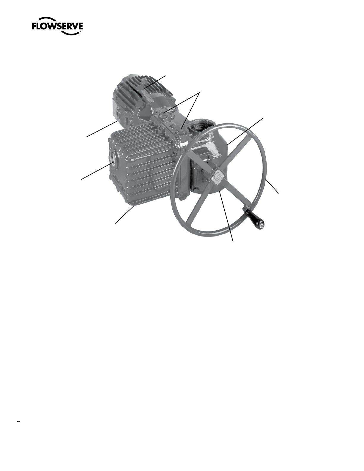
Thrust
Base
Handwheel
Electrical
Compartment
Cover
Conduit
Openings
(plugged; two additional openings
are supplied on the bottom of the
Electrical Compartment)
Housing
Declutch
Lever
Motor
Position
Indication
Window
Limitorque L120-85 Installation, Operation and Maintenance FCD LMENIM1202-00 – 11/05
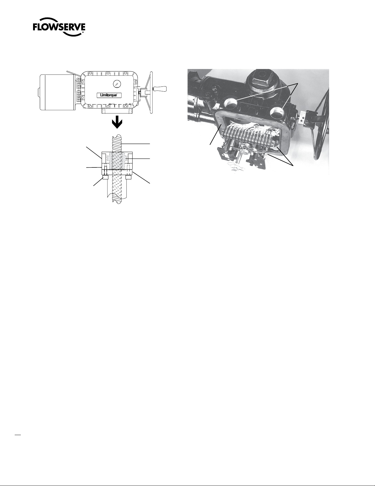
Figure 1: Limitorque L120-85 Actuator
2.2 Product Description
Your L120-85 actuator controls the opening and closing travel of
valves or other actuated devices. OPEN and CLOSED limits are
protected by Limit Switches and output torque is measured and
protected by the Torque Switches. As a result, all valves and other
actuated devices are protected from potential damage from overload,
improper seating and foreign obstructions.
Limitorque actuators may be mounted on any appropriately sized
valve in almost any position or location.
Microprocessor-based controls and monitoring devices are also
available for installation on your actuator. Contact your local Limitorque distributor or Limitorque sales office for further information.
2.3 Product Features
• Up to 850 ft-lb/1156 Nm torque capacity.
8
• Up to 45,000 lb./20250 kg thrust capacity.
• Up to 3.25"/76 mm threaded stem capacity.
• Up to 2.75"/70 mm bore capacity.
• Torque Only (Drive 1) or Torque and Thrust (Drive 2) actuators,
with removable ductile iron thrust base assembly.
• Torque unit can be removed from thrust base while valve position
is maintained.
• Standard cast iron gear case.
• All power gearing supported on anti-friction bearings.
• All gearing is alloy, heat-treated steel or bronze.
• Speed range of 24-192 RPM (60 Hz), 20-160 RPM (50 Hz).
• Declutch force independent of load on valve stem.
• Self-locking gearing available.
Page 9

Limitorque L120-85 Installation, Operation and Maintenance FCD LMENIM1202-00 – 11/05
Unit Weight
3
The following table is an L120-85 representative weight chart. It
provides the weight of several components that may be incorporated
into a typical package. Use the chart as a guideline to estimate the
weight of your particular actuator package.
Table 1: L120-85 Approximate Weight Chart
Components lb. kg
L120-85 with 40 ft-lb 1700 RPM Motor 253 558
18" Handwheel 7 15
Handwheel Adapter 5 11
Minimum Integral Control
Package and Compartment
Thrust Base Assembly (Drive 2) 67 148
Total Weight 366 lb. 807 kg
34 75
flowserve.com
9
Page 10

Limitorque L120-85 Installation, Operation and Maintenance FCD LMENIM1202-00 – 11/05
10
Page 11

Limitorque L120-85 Installation, Operation and Maintenance FCD LMENIM1202-00 – 11/05
Initial Preparation and Installation
4
4.1 Safety
WARNING: Read this Installation and Maintenance
c
Manual carefully and completely before attempting to
store, install, operate or troubleshoot your Limitorque
valve actuator. Be aware of electrical hazards within the
actuator and high pressure hazards of the attached valve
or other actuated device when installing or performing
maintenance on your L120-85 actuator.
4.2 Initial Actuator Preparation
4.2.1 Inspection and Recording
Upon receipt of the actuator, several steps should be initially followed to ensure condition of equipment and to establish proper
record keeping.
1. Carefully remove actuator from shipping carton or skid.
Thoroughly examine for any physical damage which may have
occurred during shipment. If you note any damage, immediately
report the damage to the transport company.
2. A nameplate with important information is attached to each
actuator. Record this information for future reference.
4.2.2 Short-Term Storage
(less than one year)
Units are not weatherproof until properly installed on the valve or
prepared for storage.
Store units in a clean, dry, protected warehouse away from excessive
vibration and rapid temperature changes. If the units must be stored
outside, they must be stored off the ground, high enough to prevent
them from being immersed in water or buried by snow.
1. Position the actuator in storage with motor and switch compart
ment horizontal.
2. Connect the internal heaters (if supplied) or place desiccant in
the switch compartment.
3. Replace all plastic caps or plugs with taped or doped pipe plugs
and ensure that all covers are tight.
4. If the actuator is mounted on a valve and the stem protrudes
from the unit, a suitable stem cover must be provided.
-
11
flowserve.com
Page 12
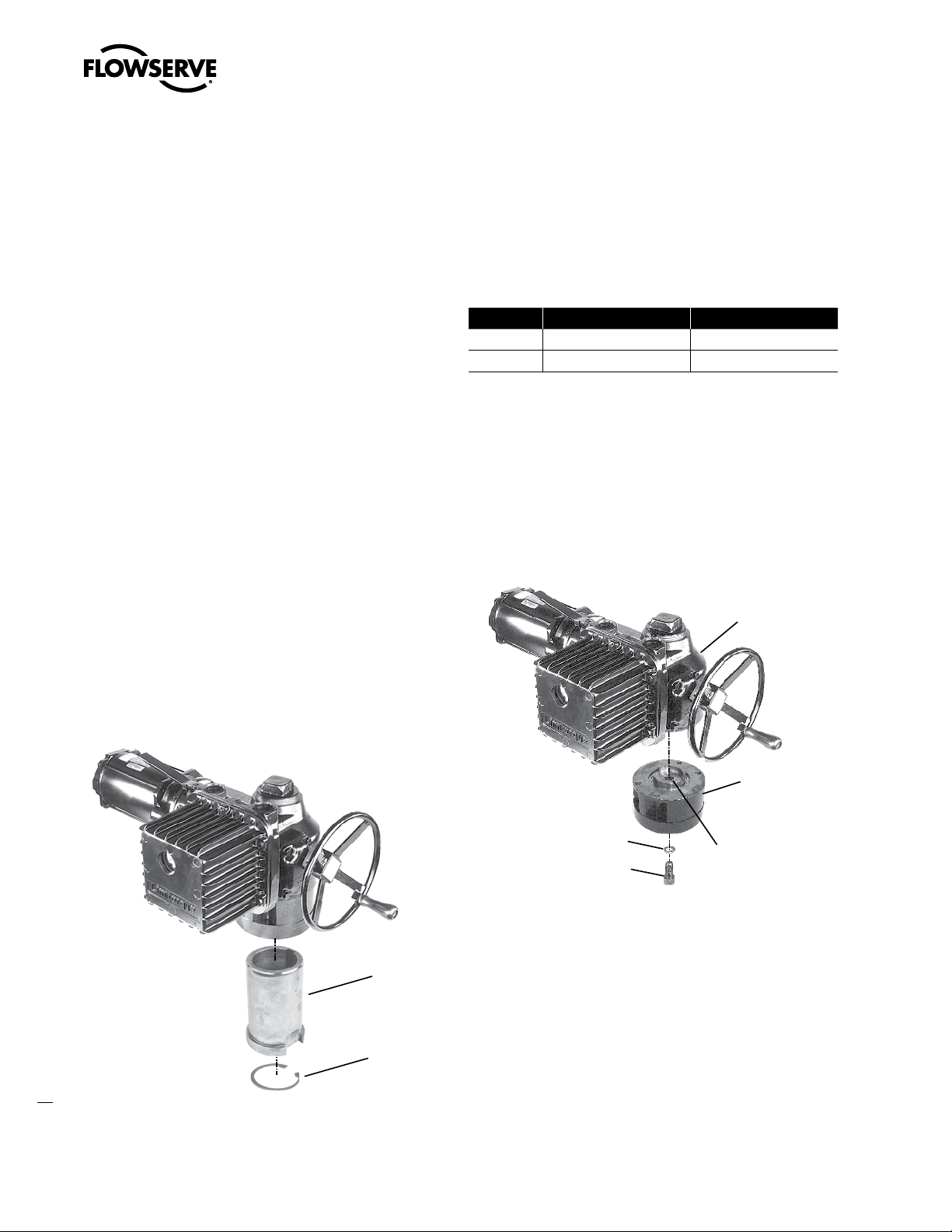
#95 Torque
Drive Nut
#98 Torque Nut
Retaining Ring
#111 Lockwasher
#110 Socket Head
Cap Screw
#100 Thrust Base
Housing
#1 Housing
#101 Thrust Base
Drive Sleeve
Limitorque L120-85 Installation, Operation and Maintenance FCD LMENIM1202-00 – 11/05
NOTE: If your unit incorporates a rising stem application, it may be
shipped with a plastic cap over the Drive Sleeve Housing. If so, in
order to store without possible corrosion occurring, install a pipe
plug or protective stem cover to protect the Drive Sleeve Housing.
NOTE: Failure to comply with recommended storage procedures
could cause the warranty to be voided. For long-term storage procedures, consult the Limitorque Customer Service Department.
4.3 Actuator Mounting
Your L120-85 is designed to perform actuation for torque only
applications (drive 1) or for torque and thrust applications (drive
2). If you are using a torque only configuration, before installing on
the valve or other actuated device, you will need to verify that the
Torque Drive Nut (piece 95) is properly bored and keyed to fit your
valve stem. If you are using a torque and thrust configuration, you
will need to verify that the Thrust Base Drive Sleeve (piece 101) is
properly threaded to fit your threaded valve stem. Use the following
procedures to check for proper fit of the Torque Drive Nut or the
Thrust Base Drive Sleeve.
A) If Torque Drive Nut has been bored and keywayed by supplier,
verify dimensions of keyway for proper compatibility with the
valve stem.
B) If Torque Drive Nut has not been bored and keywayed by sup
plier, it is provided solid (blank) to allow customer to custom
bore and key up to the maximum permissible sizes as listed:
Table 2: Torque Drive Nut: Maximum Allowable Bore and Key Sizes
Key Type Maximum Bore in. (mm) Maximum Key in. (mm)
Rectangle 2.750 (69.85) .625 x .4375 (20 x 12)
Square 2.625 (66.67) .625 x .625 (20 x 20)
4.3.2 Torque and Thrust Applications
(Drive 2) (Refer to Figure 28)
Remove Socket Head Cap Screw (piece 110) and Lockwasher (piece
111) that holds the Thrust Base Housing Assembly to the actuator
Housing (piece 1).
Figure 3: Thrust Base removal from an L120-85
12
4.3.1 Torque Only Applications (Drive 1)
(Refer to Figure 27)
Remove the Torque Nut Retaining Ring (piece 98) and Torque Drive
Nut (piece 95) from actuator.
Figure 2: L120-85 Torque Drive Nut and Retaining Ring Details
A) If the Thrust Base Drive Sleeve (piece 101) has been threaded by
supplier, verify thread compatibility with the threaded Valve Stem
by screwing Drive Sleeve onto the valve stem.
B) If Thrust Base Drive Sleeve (piece 101) has not been threaded by
supplier, it is provided solid (blank) to allow customer to custom
thread. Maximum threaded stem diameter is 3.25" (82.5 mm).
NOTE: If Thrust Base disassembly is required in order to thread
blank Thrust Base Drive Sleeve, remove Quad Rings (piece 107)
before removing Thrust Washer (piece 104) and Thrust Bearing
Page 13
Drive 1
Actuator
Mounting
Base
Actuator
Mounting
Adapter
Valve
Stem
#95 Torque
Drive Nut
Key
Note: Key is shown for reference.
It may be in one of several other
orientations in reference to the
actuator.
Limitorque L120-85 Installation, Operation and Maintenance FCD LMENIM1202-00 – 11/05
(piece 103). This will prevent damaging the Quad Rings (piece 107).
For details refer to Section 10.1, Figure 28.
4.3.3 Mounting Bolts
Mount the L120-85 actuator on the Actuator Mounting Adapter
(Drive 1) or on the Thrust Base Assembly (Drive 2). High-strength
(minimum hex head SAE-Grade 5 or ISO Metric Class socket head
cap screws) 8.8 hex head or socket head cap screws with lockwashers are recommended. The quantity and thread size of the actuator
mounting taps are as follows:
Table 3: L120-85 Actuator/Mounting Base Tap Size
Unit Type Quantity Tap Size
Drive 1 and 2
English 4 ¾–10 Tap x 1.0 in. Deep*
Metric 4 M20 x 2.5 mm x 10 mm Deep*
*Complies with F16 IOS mounting flange criteria
NOTE: Limitorque has supplied four taps for the L120-85 English
and metric units. All four securing bolts are required to retain torque
and/or thrust reaction on these units.
Installation Overview
1. Applications
A. Torque Only Applications (Drive 1)
Mount Torque Drive Nut (piece 95) in the actuator with the
Torque Drive Nut axially aligned on the Drive Sleeve (piece
25) so that the bottom of the nut is positioned inside the
actuator Mounting Base. Secure Torque Drive Nut inside
Drive Sleeve (piece 25) with Retaining Ring (piece 98). Refer
to Figure 27.
B. Torque and Thrust Applications (Drive 2)
Screw the Thrust Base Assembly onto the Threaded Valve
Stem and secure the Thrust Base Assembly to the Actuator
Mounting Base using Socket Head Cap Screws (piece 110)
and Lockwashers (piece 111).
Figure 4: L120-85 Torque Drive Nut orientation (Drive 1)
4.3.4 Stem Cover for Rising Stem
a
a
a
Before putting your actuator into operational service, check the
height of your valve stem at the full OPEN position and mount a
suitable stem cover to protect the valve stems and to prevent water
entry into the actuator.
Applications
CAUTION: Selection and installation of a stem cover which is
too short will result in damage to the valve and/or actuator.
CAUTION: Be sure to complete each step of the installation
overview before electrically operating your actuator. If your
actuator is already mounted to a valve or other actuated
device from the manufacturer, verify that the actuator is
mounted according to the following overview. Failure to
follow the installation procedures could result in personal
injury or may allow the actuator to operate improperly and
could cause damage to your equipment.
CAUTION: Ensure Retaining Ring (piece 98) is properly
engaged in the Drive Sleeve (piece 25) to secure the Torque
Drive Nut (piece 95) in place. If the Torque Drive Nut is not
properly secured, it may fall from the bottom of the actuator
when removed from customer mounting adapters.
13
flowserve.com
Page 14
Drive 2 Actuator
Mounting Base
Actuator
Mounting
Adapter
Threaded
Valve Stem
#101 Thrust Base
(Drive Sleeve)
Thrust Base
Assembly
#110 Socket Head
Cap Screws
#111 Lockwashers
Conduit Pipe
Plug Locations
Conduit Pipe
Plug Locations
Electrical
Compartment
Limitorque L120-85 Installation, Operation and Maintenance FCD LMENIM1202-00 – 11/05
Figure 5: L120-85 Thrust Base Assembly orientation (Drive 2)
4.4 Verifying Motor Rotation
Direction
4.4.1 Initial Electrical Connections
WARNING: Hazardous Voltage. No electrical power should
c
be connected until all wiring and Limit Switch adjustments have been completed. Once power is supplied to
unit, exercise caution if cover is not installed.
1. Open the Electrical Compartment Cover (piece 200-1) and
remove the Conduit Pipe Plugs from the opening(s) most conveniently located for your power leads and other cabling.
Figure 6: Electrical Compartment and Conduit Pipe Plug openings
2. Adjust the Limit Switches, MDPI (Mechanical Dial Position
Indicator) and Potentiometer following the procedures outlined
in Sections 4.5 and 4.7.
3. Ensure Torque Switch is set properly for your application. In
most cases, adjustments are not needed, but if changes are
required, see Section 4.6, “Torque Switch Settings and Wiring”.
4. Connect wiring to Terminal Strips provided on the actuator.
Refer to the wiring diagram supplied with your specific actuator.
“Fork-type” terminal connections are recommended.
5. Be sure any unused conduit entrances are plugged with metal
Conduit Pipe Plugs.
Notes:
a) Explosion-proof actuators require approved “sealing fittings”
installed in accordance with the National Electric Code.
b) Submersible actuators require approved “sealing fittings” in
order to prevent water entering the actuator.
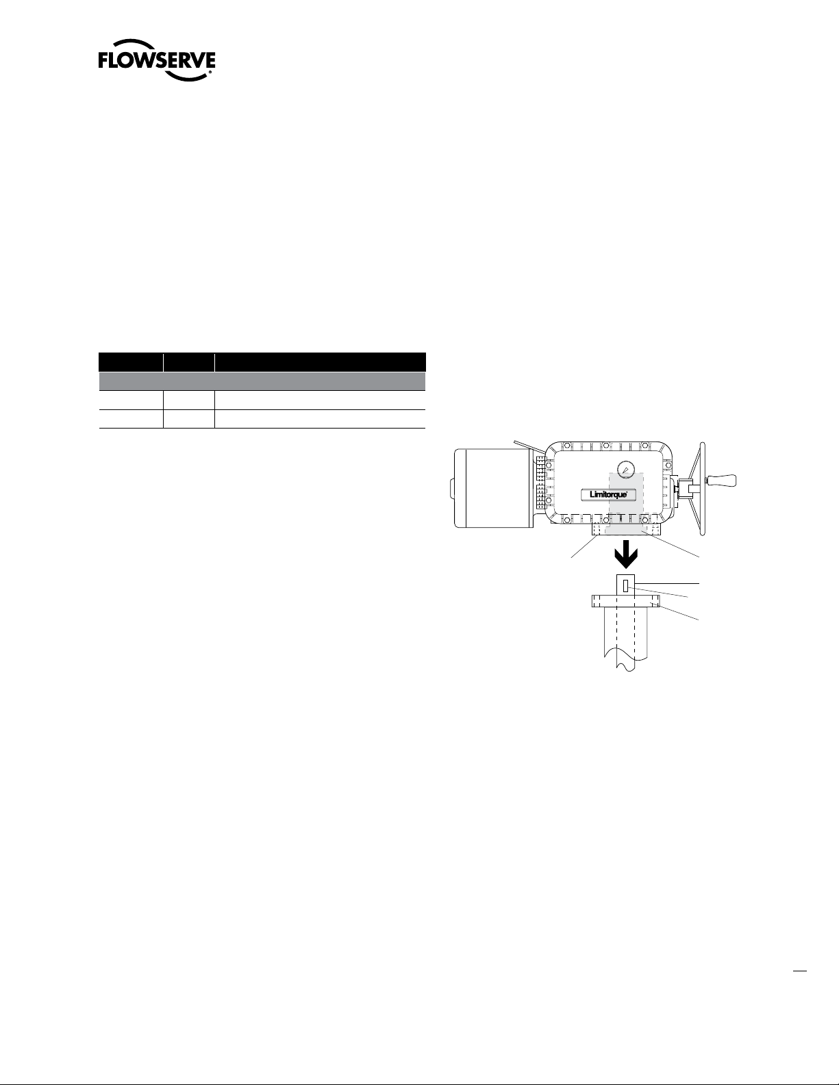
6. Attach grounding wire to Grounding Lug (piece 14).
14
Page 15

Grounding Lug
Limitorque L120-85 Installation, Operation and Maintenance FCD LMENIM1202-00 – 11/05
Figure 7: Grounding Lug location
7. Inspect actuator for proper lubrication. Refer to “Lubrication”
Section 6.1 for lubrication instructions.
8. Verify that Motor rotation is operating in the proper direction; the
Motor rotation will have a direct impact on the Limit Switch and
Torque Switch functions. Follow the procedure “Verifying Motor
Rotation Direction” in Sections 4.4.2, 4.4.3 and 4.4.4).
9. Close Electrical Compartment Cover (piece 200-1).
10. Unit is now ready for electrical operation. Continue to “Electrical
Start-up Procedure” in Section 5.3.
4.4.2 Motor rotation (phasing) and OPEN/
CLOSE pushbutton operation.
It is very important to check for correct motor rotation to ensure that
serious damage to your valve or other equipment does not occur.
If the actuator motor rotates in the wrong direction, damage could
occur by over-torquing equipment into a seated position.
Prior to being shipped from the factory, each actuator is inspected to
verify proper operation of the Torque and position Limit Switch and
to ensure that they function correctly (i.e. closes when the CLOSE
pushbutton is depressed, opens with the OPEN pushbutton, etc.).
These inspections are made with a properly phased power source
connected as described in the actuator manual.
CAUTION: To ensure proper operation and to prevent your
a
actuator or other actuated equipment from damage, verify
that your unit is properly connected to its power source.
NOTE: Your application may vary from the following standard wiring
configurations for Three-phase, Single-phase and DC motors. Refer
to your actuator wiring diagram for user-specific wiring configuration.
4.4.3 Three-Phase Motor
1. Using the Handwheel, move the valve to a midtravel position
(midtravel position allows electrical operation in the valve “safe”
area and keeps the OPEN and CLOSED Limit Switches from tripping while testing motor direction).
2. Be prepared to immediately remove power should the actuator
run the wrong way.
3. Test motor direction by momentarily pressing the OPEN push
button:
A) If the actuator moves toward CLOSED, immediately turn all
power OFF and reverse the motor leads T1 and T3.
NOTE: Refer to your actuator wiring diagram for user-specific wiring configuration.
B) If the actuator moves toward OPEN, the motor is wired
properly for the application.
-
4.4.4 DC Motor
1. Using the Handwheel, move the valve to a midtravel position
(midtravel position allows electrical operation in the valve “safe”
area and keeps the OPEN and CLOSED limit switches from tripping while testing motor direction).
2. Test motor direction by momentarily pressing the OPEN push
button:
A) If the actuator moves toward CLOSED, immediately turn all
power OFF and reverse the motor leads A1 and A2.
NOTE: Refer to your actuator wiring diagram for user specific wiring configuration.
B) If the actuator moves toward OPEN, the motor is wired
properly for the application.
-
4.5 Limit Switch Settings
The standard L120-85 Limit Switch has 16 contacts. The OPEN/
CLOSE Limit Switch (first eight contacts) has two Rotor Sets, one
for the OPEN position and one for the CLOSED position. Each Rotor
Set has four electrical contacts which can be arranged in any combination of normally OPEN and normally CLOSED. The SPARE Limit
Switch (second eight contacts) has two additional Rotor Sets with
four contacts each that can be set to operate anywhere between the
OPEN and CLOSE positions. These can be used to stop the valve in
mid-travel or to interlock with other equipment such as pumps, fans,
mixers, etc. Refer to Figure 8.
15
flowserve.com
Page 16

NOTES
1. Contact Open
2. Contact Closed
3. All limit switch trip points
are fully adjustable.
.
BY-PASS CIR.
IND LIGHT
OPEN LIMIT
BY-PASS CIR
IND LIGHT
CLOSE LIMIT
SPARE
SPARE
SPARE
SPARE
SPARE
SPARE
SPARE
SPARE
FULLY
OPEN
A
B
FULLY
CLOSED
VALVE SHOWN IN FULL OPEN POSITION
INDICATION
INDICATION
LIMIT SWITCH CONTACT DEVELOPMENT
VALVE POSITION
ROTOR
OPEN
CLOSE
INT.1
INT.2
FUNCTION
1
2
3
4
5
6
7
8
9
10
11
12
13
14
15
16
CONTACT
Limitorque L120-85 Installation, Operation and Maintenance FCD LMENIM1202-00 – 11/05
Figure 8: Limit Switch Rotor development
THE LIMIT SWITCH IS NOT PRESET at the Limitorque factory, and
must be set after mounting on the valve or other associated equipment. If your L120-85 actuator has been shipped already installed
on your equipment, your actuator should have the Limit Switch set
for your application. If your actuator is not already installed on your
equipment or needs resetting, use the following instructions to make
the appropriate settings.
The following instructions for setting the Limit Switches are based
on the typical orientation for most actuator applications (CCW
to OPEN and CW to CLOSE). Consult the applicable wiring
diagra located in the actuator Electrical Compartment for your specific Limit Switch development.
ing unseating, this momentary bypass is applied. The OPEN Rotor
actuates at the full OPEN position causing contact 1 to open as soon
as the valve moves in the close direction, thus returning the Torque
Switch function to the control circuit.
Contact 2
is normally used for a Remote Valve Position Indication
Lamp. As shown in Figure 8, the lamp will be turned ON when the
valve reaches the full OPEN position.
Contact 3
is for the Local Position Indication Lamp; included as part
of the actuator assembly when required. This switch turns the green
lamp/LED OFF in the full OPEN position, leaving the red lamp/LED
energized and indicating that the valve is OPEN.
Contact 4
is the OPEN Limit Switch which opens the control circuit
to de-energize the Motor at full OPEN position.
The CLOSE Rotor consists of contacts 5 through 8. This Rotor is set
to change state at the full CLOSE position. Switch functions are as
follows:
Contact 5
is the OPEN Torque Switch bypass. After the valve
has been tightly closed, it may stick when it is first opened which
would cause the Torque Switch Contacts to break. To momentarily
overcome this sticking, the OPEN Torque Switch is bypassed. This
OPEN Torque Switch bypass is part of the closed valve position
rotor so that as soon as the valve moves in the OPEN direction, the
bypass contact opens and the OPEN Torque Switch control function
is returned.
Contact 6
is normally used for a Remote Valve Position Indication
Lamp. As shown in Figure 8, the lamp will be turned ON when the
valve reaches the full CLOSE position.
Contact 7
is for the Local Position Indication Lamp; included as part
of the actuator assembly when required. This switch turns the red
lamp/LED OFF in the full CLOSE position, leaving the green lamp/LED
energized and indicating the valve is in the full CLOSE position.
16
4.5.1 Basic Theory of Operation
The Limit Switch (piece 305) is driven directly by the Worm Shaft
through the Limit Switch Pinion. Therefore, the Limit Switch is
directly connected to the output of the actuator. Once the Limit
Switch is properly set, it measures the position of the valve, or other
equipment, in the ELECTRIC or MANUAL operating modes.
The OPEN Rotor consists of contacts 1 through 4. These switches
are set to change state at the full OPEN position. The switch functions are as follows:
Contact 1
is the CLOSED Torque Switch bypass circuit. It’s purpose
is to allow the electric actuator to apply its full torque to unseat a
backseated valve. When a valve is manually backseated to prevent
packing leakage, it may stick momentarily when first operated. To
prevent the CLOSE Torque Switch from stopping the actuator dur-
Contact 8
is the CLOSE Limit Switch that opens the control circuit to
de-energize the Motor at full CLOSE position.
WARNING: Do not manually operate actuator with devices
c
other than installed Handwheel and Declutch Lever. Using
additive force devices (cheater bars, wheel wrenches,
pipe wrenches or other devices of this nature) on the
actuator Handwheel or Declutch Lever may cause serious
personal injury and/or damage to the actuator or valve.
WARNING: Hazardous Voltage. Make sure all power is
c
OFF before opening the Electrical Compartment Cover or
making the following settings.
Page 17

Gear Frame
Assembly
Intermediate Shafts
(A, B, C, and D)
Drive Pinion
Clutch Screw
Rotor Cams
Limitorque L120-85 Installation, Operation and Maintenance FCD LMENIM1202-00 – 11/05
4.5.2 Adjustment—General
Tools required:
• The cross-slotted Intermediate Shafts A, B, C and D have been
designed for use with a 6" No. 2 Phillips screw driver shank
chucked into a variable speed reversible electric drill. (See figure 9
for Limit Switch components).
• Phillips Head or Flat Head screwdriver.
WARNING: Potential Explosion Hazard. Do not use a vari-
c
able speed reversible electric drill for setting the Limit
Switch in an explosive environment.
CAUTION: When setting Limit Switch Rotor Cams using a
a
variable speed reversible electric drill, Do Not run drill at
speeds higher than 200 RPM. Operating drill at high speeds
can cause damage to gearing within the Limit Switch.
CAUTION: The Worm on the Worm Shaft Assembly is avail-
a
able in two different ratios 19:1 and 38:1. To avoid damage
to the gearing mechanisms, be sure you change the Limit
Switch Drive Pinion gear if the Worm gear ratio is changed.
NOTE: The Limit Switch is available with a 4 Gear Set or a 5 Gear
Set within the Gear Frame Assembly. The number of Gear Sets
built into your specific Limit Switch will determine the number
of maximum Drive Sleeve rotations required to go the full range
of the Limit Switch. A four Gear Set with 19:1 and 38:1 has a
maximum rotation of 902.25 Drive Sleeve rotations. A five Gear
Set with 19:1 and 38:1 has a maximum rotation of 9022.5 Drive
Sleeve rotations.
Figure 9: L120-85 Limit Switch Components
4.5.3 Setting the OPEN Limit Switch
1. De-engerize electrical circuit to the actuator.
2. Open Electrical Compartment Cover (piece 200-1).
3. Put the actuator into MANUAL operation by moving the Declutch
Lever in the direction of the arrow on the lever until the Declutch
Lever locks in place.
4. Turn the Handwheel CCW
OPEN position. While turning the Handwheel, note the direction
of the Intermediate Shaft that corresponds to the Open Rotor
Group. See figure 9.
NOTE: Most applications require turning the Handwheel CW to
obtain the full CLOSE position and CCW to obtain full OPEN
position. The actuator Drive Sleeve rotates in a CW direction
to the CLOSE position and CCW to the OPEN position. The
Limit Switch Intermediate Shafts rotate in a CCW direction
to the CLOSE position and CW to the OPEN position. If your
application is configured differently, keep in mind that the descriptions in this manual will describe rotation directions opposite of your
application.
5. Once the valve is fully OPEN, turn the Handwheel back toward
CLOSE approximately one full turn. This will allow for coasting
during motor operation.
CAUTION: Do not operate the actuator when the Clutch
a
Screw is in a fully depressed position; loss of the contact
setting will occur and the Setting Rod will be damaged.
CAUTION: For highly geared actuators, one turn of the
a
handwheel may not be sufficient to allow for coast of moving parts. Refer to valve manufacturer setting requirements
in these cases.
to move the valve to the full
6. Push in Clutch Screw and turn CW
latch in a depressed position.
7. Limit Switch Rotor Cams
A. If your Limit Switch Rotor Cams did not trip at the full
OPEN position point, turn the Intermediate Open Shaft in a
CW direction until the Open Limit Rotor Cam rotates
90° to make an OPEN contact (OPEN limit trip point = Rotor
Cam in a vertical orientation to make an OPEN contact);
see figure 10 for orientation. Once you have reached the
full OPEN position point, use the Handwheel to rotate the
Intermediate Shaft slowly in the CCW direction until
the Rotor just trips again.
B. If your Limit Switch Rotor Cams did trip before reaching
the full OPEN position point, leave the valve at the full OPEN
one quarter turn to
flowserve.com
17
Page 18

OPEN
Contact
CLOSED
Contact
Contact
Plunger
Rotor
Cams
Limitorque L120-85 Installation, Operation and Maintenance FCD LMENIM1202-00 – 11/05
position point and turn the Intermediate Open Shaft in a
CCW direction until the Rotor Cam rotates 90° to
make an OPEN contact (OPEN limit trip point = Rotor Cam
in a vertical orientation to make an OPEN contact). Once
you have reached the full OPEN position point, rotate the
Intermediate Shaft slowly in the CW direction until the
Rotor just trips again.
Figure 10: Limit Switch OPEN/CLOSED Rotor Cam orientation
4. Turn the Handwheel CW
CLOSED position. While turning the Handwheel, note the direction of the Intermediate Shaft that corresponds to the Closed
Rotor Group.
NOTE: Most applications require turning the Handwheel CW to
obtain the full CLOSE position and CCW to obtain full OPEN
position. The actuator Drive Sleeve rotates in a CW direction
to the CLOSE position and CCW to the OPEN position. The
Limit Switch Intermediate Shafts rotate in a CCW direction
to the CLOSE position and CW to the OPEN position. If your
application is configured differently, keep in mind that the descriptions in this manual will describe rotation directions opposite of your
application.
5. Once the valve is fully CLOSED, turn the Handwheel back toward
OPEN approximately one full turn. This will allow for coasting
during motor operation.
CAUTION: Do not operate the actuator when the Clutch
a
Screw is in a fully depressed position; loss of the
contact setting will occur and the Setting Rod will be
damaged.
to move the valve to the full
18
8. Before operating the actuator, depress and turn the Clutch Screw
CCW one-quarter turn to the spring release position.
Insert a screwdriver into each of the Intermediate Shafts and
“rock” them CW and CCW a few times to ensure all
the gearing is seated well.
4.5.4 Setting the CLOSE Limit Switch
1. De-engerize electrical circuit to the actuator.
2. Open Electrical Compartment Cover (piece 200-1).
3. Put the actuator into MANUAL operation by moving the Declutch
Lever in the direction of the arrow on the lever until the Declutch
Lever locks in place.
CAUTION: For highly geared actuators, one turn of
a
the handwheel may not be sufficient to allow for coast
of moving parts. Refer to valve manufacturer setting
requirements in these cases.
6. Push in Clutch Screw and turn CW
in a depressed position. See Figure 9 for Limit Switch nomenclature.
7. Limit Switch Rotor Cams
A. If your Limit Switch Rotor Cams did not trip at the full
CLOSE position point, turn the Intermediate Close Shaft
in a CCW direction until the Close Limit Rotor Cam
rotates 90° to make an OPEN contact (CLOSE limit trip
point = Rotor Cam in a vertical orientation to make an OPEN
contact). Once you have reached the full CLOSED position
point, rotate the Intermediate Shaft slowly in the CW
direction until the Rotor just trips again.
B. If your Limit Switch Rotor Cams did trip before reaching
the full CLOSE position point, leave the valve at the full
CLOSE position point and turn the Intermediate Close Shaft
in a CW direction until the Close Limit Rotor Cam
rotates 90° to make an OPEN contact (CLOSE limit trip
point = Rotor Cam in a vertical orientation to make an OPEN
contact). Once you have reached the full CLOSE position
point, rotate the Intermediate Shaft slowly in the CCW
direction until the Rotor just trips again.
one-quarter turn to latch
Page 19

ID Limiter
Plate (not shown)
#300-4 Torque Switch
Adjustment
Screws
#300-8 Balancing
Screws
Mounting
Screw Hole
Torque Arm
Red dot indicates
L120-85 Torque Switch
Typical OPEN
contact assembly
(18 & 18C)
#300-2 & 300-3
Index Arm
Typical CLOSE
contact assembly
(17 & 17C)
Limitorque L120-85 Installation, Operation and Maintenance FCD LMENIM1202-00 – 11/05
8. Before operating the actuator, depress and turn the Clutch Screw
CCW one quarter turn to the spring release position.
Insert a screwdriver into the Intermediate Shafts and “rock”
them CW and CCW a few times to ensure all the
gearing is seated well.
4.6 Torque Switch Setting
and Wiring
WARNING: Hazardous Voltage. Turn power OFF before
c
opening the Electrical Compartment Cover or making any
adjustments to the Torque Switch.
NOTE: Removal or modification of the Torque Switch Limiter Plate
will void the actuator warranty. Do not exceed the torque setting
indicated by the Torque Switch Limiter Plate without contacting the
Limitorque Customer Service Department.
The L120-85 unit is equipped with a double-acting Torque Switch
that has been factory preset according to the required torque value
provided by the valve manufacturer or other associated equipment
supplier. Further Torque Switch adjustment should not be required;
however, the Torque Switch may be reset from positions 1 through
5 (5 being the highest input torque requirement) by adjusting the
Torque Switch Adjustment Screws unless it is limited by the Limiter
Plate. See figure 11 for Torque Switch nomenclature.
4.6.1 Basic Theory of Operation
As torque is developed by the actuator, the Worm moves axially and
causes compression on the Spring Pack Assembly (components of
the Worm Shaft Assembly (piece 15)). The Spring Pack Assembly
is calibrated so that a given amount of spring compression equates
to a given amount of output torque. Axial Worm Shaft Assembly
movement causes the Torque Switch Shaft (piece 300-13) to move,
therefore engaging the Torque Switch measurement device. Once the
Torque Switch is properly set, it measures valve, or other equipment,
torque input in the ELECTRIC or MANUAL operating modes.
4.6.2 Setting the Torque Switch
CAUTION: Installing or adjusting the Torque Switch with the
a
actuator in a loaded condition will result in loss of torque
protection. Before adjusting or installing the Torque Switch,
place the actuator in MANUAL mode and turn the Handwheel in the direction necessary to release the torque load
on the Worm Shaft Assembly.
NOTE: If Torque Switch replacement is required, be sure to use an
L120-85 Torque Switch rather than replacing with an L120-10 thru
40 Torque Switch. The L120-85 Torque Switch Torque Arm is rotated
10° from the position of the Torque Arm on the L120-10 thru 40
Torque Switch (the red dot on the Torque Switch Shaft indicates an
L120-85 Torque Switch).
Figure 11: Torque Switch Components
1. Turn all power to the actuator OFF.
2. Loosen the Torque Switch Adjustment Screws (piece 300-4) on
the OPEN or CLOSED side of the Torque Switch.
3. Move Index Arm (piece 300-2 or piece 300-3) to desired torque
setting. The higher number indicates an increased torque and/or
thrust output requirement.
4. Tighten the Torque Switch Adjustment Screws (piece 300-4).
5. Turn power ON and operate the valve electrically to seat the valve
or other device and to ensure tight shut-off.
4.6.3 Balancing the Torque Switch
If the Torque Switch has been removed from the unit or if you are
installing a new Torque Switch, it must be rebalanced using the following procedure:
1. Ensure that the actuator is in MANUAL mode and the load is
removed from the Worm Shaft Assembly.
2. Make note of the current OPEN and CLOSED Torque Switch set
tings before reinstalling the Torque Switch.
3. Loosen Torque Switch Adjustment Screws (piece 300-4) and
position both Index Arms (piece 300-2) and (piece 300-3) at the
1 setting; tighten the Torque Switch Adjustment Screws. Make
sure the Index Marks are aligned. See figure 15.
4. Loosen Balancing Screws (piece 300-8) and install the Torque
Switch. When properly installed, the base of the Torque Switch
flowserve.com
-
19
Page 20

Typical CLOSE
contact assembly
(17 & 17C)
NOTE: 17C and 18C attach
to screws (not shown) on
the bottom of the switch.
#300-4 Torque Switch
Adjustment Screws
Typical OPEN
contact assembly
(18 & 18C)
18
18C
17
17C
#523 Round
Head
Machine
Screw
#522 MDPI
Pointer
MDPI
Dia
l
Plate
Limitorque L120-85 Installation, Operation and Maintenance FCD LMENIM1202-00 – 11/05
is flush against the Actuator Compartment and the hole for the
Mounting Screw is aligned. Install the Mounting Screw.
5. Tighten the Balancing Screws. The Torque Switch is now bal
anced and ready for Index Arm (piece 300-2 and piece 300-3) to
be returned to their original settings.
6. Follow your wiring diagram to connect Torque Switch wiring.
4.6.4 Rewiring the Torque Switch for
Non-Standard Drive Sleeve Rotation
CAUTION: Double check your wiring diagram to verify that
a
your Torque Switch is wired appropriately for your application. The Torque Switch will not protect your valve from
over-torque if you do not apply appropriate wiring for your
application.
L120-85 actuators are typically supplied with a CCW Drive
Sleeve rotation to open a valve. The two Torque Switches are marked
OPEN (CCW ) and CLOSE (CW ) based upon CCW
Drive Sleeve rotation to open the valve. The MDPI on the L120-85
is typically mounted for the full CCW rotation to indicate the
OPEN position (100%). If opposite drive sleeve rotation is required
(CCW to CLOSE a valve), the following torque switch modifications are required.
4. Remove the Mechanical Dial Position Indicator Plate and flip
over for indication of CCW rotation to the valve’s CLOSED
position. See figure 13 for MDPI Dial Plate.
5. Reverse the OPEN/CLOSE directional arrow on the Handwheel.
4.7 Position Indication
The MDPI is used to indicate the current position of the valve or
other actuated devices. Adjustments must be done after mounting
the actuator on the application. If your supplier has not set the MDPI
or your application has changed and requires resetting, use the following procedure to complete the MDPI settings.
WARNING: Hazardous Voltage. Turn power OFF before
c
opening the Electrical Compartment Cover, calibrating the
MDPI or installing the Remote Voltmeter Indicator.
4.7.1 Local Position Indication
1. Turn OFF all power to the actuator.
2. Manually position the valve in the fully CLOSED position.
3. Loosen the Round Head Machine Screw (piece 523) on the
MDPI Pointer (piece 522).
20
WARNING: Hazardous Voltage. Turn power OFF before
c
opening the Electrical Compartment Cover or making any
adjustments to the Torque Switch.
1. Turn power to the actuator OFF before changing Torque Switch
wiring.
2. Reverse the OPEN and CLOSE Torque Switch labels on the ID
Limiter Plate. See figure 11.
3. Interchange OPEN Torque Switch wires 18 and 18C with
CLOSED wires 17 and 17C (refer to your wiring diagram for
other Torque Switch wiring configurations).
Figure 12: Reversing Torque Switch wiring
Figure 13: Aligning MDPI Pointer for Fully CLOSED Position
4. Move the MDPI Pointer to the (CLOSED) position.
NOTE: If your application uses CW Handwheel rotation to
OPEN, flip the MDPI Plate over to properly orient the OPEN and
CLOSED position on the MDPI Plate.
5. Tighten the Round Head Machine Screw on the MDPI Pointer.
Page 21

P1 P2 P3
CLOSED
Valve Position
1
4
1
2
3
4
OPEN
LIMITORQUE CORPORATION
LYNCHBURG V A.
25 watt, 50 ohm Potentiometer
type Variable Resistor mounted
in a Limitorque Actuator Housing
10.00
Digital Multitester
Control voltage range
110 volts to 480 volts
175 watt, 2500 ohm
Adjustable Resistor
located adjacent to
Remote Position
Indicator for voltage
adjustment
Remote
Voltmeter
Indicator
Ohmmeter
for calibration
Adustable
Resistor Slider
Mounting
Surface
Limitorque L120-85 Installation, Operation and Maintenance FCD LMENIM1202-00 – 11/05
4.7.2 Remote Position Indication
NOTE: Typical voltmeter remote indicators furnished by Limitorque
are built to accept a maximum of 10 volts. In order to make voltmeter adjustments, you will need a separate voltmeter with a scale
suitable for the maximum incoming control voltage.
1. Mount the Adjustable Resistor as close as possible to the
Remote Voltmeter Indicator.
2. Turn power to actuator OFF and connect all wiring as shown in
Figure 14. For now, connect the wires leading to the Remote
Voltmeter Indicator to your test meter so you can conduct voltage readings during the setup.
3. Move the Adjustable Resistor Slider to the extreme opposite end
of the Resistor from the Power Connection.
4. Open the Electrical Compartment Cover (piece 200-1). Loosen
the Hex Head Retaining Nut at the base of the Potentiometer
Bracket and dis-engage the Spur Gear from the Potentiometer
Drive Gear. This will allow manual rotation of the Potentiometer
Assembly. See figure 14.
5. Manually position the valve in the fully CLOSED position. As
you are rotating the Handwheel to the CLOSED position, notice
the direction the Potentiometer Spur Gear would be turning the
Potentiometer Shaft/Wiper Arm inside the Potentiometer.
WARNING: Hazardous Voltage. Use extreme caution
c
if power is ON and Electrical Compartment Cover is
removed.
7. Turn power to the actuator ON. Your Test Meter should read “0”
or almost “0”. If not, go back through the above steps 1–7 to get
your Potentiometer calibrated to the proper end-of-travel.
8. Now manually position the valve in the fully OPEN position.
9. Move the Adjustable Resistor Slider toward the Power Connec
-
tion end until the Test Meter reads 10 volts.
10. Turn actuator power OFF, disconnect the Test Meter and connect
the leads to the Remote Voltmeter Indicator.
11. Turn actuator power ON. Your Remote Voltmeter Indicator
should read full OPEN.
12. Further adjustment may be necessary. If the Remote Voltmeter
Indicator reads less than full OPEN, carefully move the Adjustable Resistor Slider ahead being careful not to exceed the full
OPEN position on the Remote Voltmeter Indicator. If the Indicator reads more than “0” when the valve is CLOSED, repeat this
procedure.
13. When the Indicator properly shows valve position, lock the
Adjustable Resistor Slider in place.
6. When the valve is CLOSED, turn the Potentiometer Shaft to the
end-of-travel position that corresponds to the CLOSED position
of the Potentiometer. Carefully reposition the Potentiometer
Spur Gear onto the Potentiometer Shaft to re-engage with the
gear train. Re-tighten Hex Head Retaining Nut at the base of the
Potentiometer Bracket.
Figure 14: Remote Position Indicator Calibration Configuration
21
flowserve.com
Page 22

Pot Lead
End Connection
Pot Lead
Center Connection
Ohmmeter
Hex Head
Retaining Nut
Pontentiometer
Spur Gear
Pontentiometer
Drive Gear
Limitorque L120-85 Installation, Operation and Maintenance FCD LMENIM1202-00 – 11/05
4.7.3 Setting the Potentiometer
If your L120-85 actuator includes a Feedback Potentiometer supplied
for remote valve position indication, use an ohmmeter to calibrate
the position of the Potentiometer. Typically, the Potentiometer Spur
Gear is shipped from the factory dis-engaged from the Potentiometer Drive Gear. If your supplier has not re-engaged and calibrated
the Potentiometer, use the following procedure to complete the
Potentiometer setup.
WARNING: Hazardous Voltage. Turn power OFF before
c
opening the Electrical Compartment Cover or calibrating the Feedback Potentiometer. Use extreme caution if
power is ON and the Electrical Compartment is OPEN.
1. Turn all power to the actuator OFF.
2. Using the Handwheel, position the actuator to mid-travel (valve
at the 50% position).
3. Disconnect the Potentiometer Wiring Harness from the Intercon
nect Board or Terminal Strip.
4. Using an ohmmeter, verify that the potentiometer is in midtravel. The resistance from each End Connection to the Center
Connection should be half of the full resistance of the Potentiometer. Example: a 1000 ohm potentiometer should read
approximately 500 ohms from one of the End Connections to the
Center Connection. If the reading is not correct, proceed to step
5. If the reading is correct proceed to step 11.
Figure 15: Potentiometer Calibration configuration
Figure 16: Loosening Potentiometer Assembly
-
6. If the Potentiometer Spur Gear is not engaged with the Potentiometer Drive Gear continue to step 7.
7. Rotate the Potentiometer Spur Gear until the correct readings
are obtained as described in step 3.
8. Carefully reposition the Potentiometer Spur Gear to re-engage
with the gear train.
9. Re-tighten Hex Head Retaining Nut at the base of the Potentiom
eter Bracket.
-
22
5. If the Potentiometer Assembly is engaged with the Potentiometer Drive Gear: Loosen the Hex Head Retaining Nut at the base
of the Potentiometer Bracket and dis-engage the Spur Gear from
the Potentiometer Drive Gear. This will allow manual rotation of
the Potentiometer Spur Gear. Continue to step 7.
10. Recheck ohmmeter reading to assure Potentiometer adjustment
was not changed when Potentiometer was tightened to Potentiometer Bracket. If Potentiometer setting is not accurate, repeat
steps 5–9. If ohmmeter reading is accurate, proceed to step 11.
11. Disconnect the ohmmeter and reconnect the Potentiometer wir
ing to the Interconnect Board or Terminal Strip.
-
Page 23

Limitorque L120-85 Installation, Operation and Maintenance FCD LMENIM1202-00 – 11/05
Operation
5
L120-85 actuators are always available for motor operation when
the motor is energized. Do not force the Declutch Lever into the
motor operation position. The Declutch Lever returns to motor
operation position automatically when the motor is energized.
NOTE: Refer to the Illustrated Parts Breakdown in Section 10.1 as
you step through the Description of Operation and the Assembly/
Disassembly procedures.
5.1 Description
of Motor Operation
In motor operation, the Motor Cam (piece 38) drives the Clutch
Assembly (piece 19-1, 2, and 3) which is splined on the outer
diameter and mates with the internal splines of the Clutch Pinion
Assembly (piece 18-1, 2 and 3). The helical gear teeth on the Clutch
Pinion (piece 18-1) mate with the Wormshaft Gear (piece 35) teeth.
The Clutch Pinion and Wormshaft Gear are always engaged. The
Wormshaft Gear is keyed to the Wormshaft (piece 15-1) which is
keyed to the Worm (piece 15-2). Rotation of the Wormshaft/ Worm
Assembly turns the Worm Gear (piece 21). Lugs on the Worm Gear
engage lugs on the outer diameter of the Drive Sleeve (piece 25).
Hammerblow or no lost motion is selected by the assembly arrangement of the Worm Gear and Drive Sleeve Lugs. Lugs at the base
of the Drive Sleeve can drive either a Torque Drive Nut (similar to
L120-10 through 40) or they can drive the lugs of the Thrust Stem
Nut contained in the type Drive 2 Thrust Base Assembly.
5.2 Description
of Manual Operation
WARNING: Do not manually operate actuator with devices
c
other than installed Handwheel and Declutch lever. Using
additive force devices (cheater bars, wheel wrenches,
pipe wrenches or other devices of this nature) on the
actuator Handwheel or Declutch Lever may cause serious
personal injury and/or damage to the actuator or valve.
The L120-85 actuator has a Handwheel (piece 29) for manual
operation. The unit can be manually operated any time the Motor is
not energized. To manually operate the L120- 85, push the Declutch
Lever (piece 9) in the direction of the arrow until it latches in place.
Pushing the Declutch Lever rotates the Declutch Shaft which is
23
flowserve.com
Page 24

Limitorque L120-85 Installation, Operation and Maintenance FCD LMENIM1202-00 – 11/05
keyed to the Declutch Link (piece 7-1). The Declutch Link engages
the Clutch Ball Bearing (piece 19-2) which disengages the Clutch
from the Motor Cam and engages the Handwheel Lugs (piece 3-1).
The Clutch Latches (piece 32) hold the Clutch Assembly in MANUAL
operation until the Motor is energized. Lobes on the Motor Cam
(piece 38) cause the Clutch Latches to release when the Motor is
energized. The spring-loaded Clutch (piece 19-1) reengages with
the lugs on the Motor Cam. The Declutch Lever will automatically
disengage when the Motor begins operating.
5.3 Electrical Start-up Procedure
1. Check that the actuator has been correctly lubricated. This is
particularly important if the actuator has been in long-term storage.
2. Ensure that the Limit Switch and Torque Switch have been
properly set.
3. If the valve stem is not visible, remove the Pipe Plug (piece 45)
to observe the output direction of the Drive Sleeve (piece 25).
4. Engage MANUAL operation and hand crank actuator well away
from the OPEN or CLOSED end-of-travel.
5. Turn power ON and push the OPEN button to electrically operate
the actuator.
6. Check output rotation; if Motor rotation (phase) is correct,
the valve will begin to open. If the valve begins to close,
Stop Immediately.
7. Correct the Motor rotation by following the procedure “Verifying
Motor Rotation Direction” in Section 4.4.
8. The actuator should operate correctly and will stop at the end of
travel by the Torque and Limit Switch functions.
9. Replace Pipe Plug (piece 45).
10 If your actuator configuration has a control package, consult you
specific controls package Installation and Maintenance Manual
for proper set-up and calibration.
24
Page 25

Limitorque L120-85 Installation, Operation and Maintenance FCD LMENIM1202-00 – 11/05
Maintenance
6
6.1 Lubrication
6.1.1 Initial Inspection
NOTE: Before operating your actuator, inspect it for proper lubrication, (especially if it has been stored for a long period of time).
No seal can remain absolutely tight at all times; therefore, it is not
unusual to find a very small amount of weeping around shaft seals
— especially during long periods of idleness such as storage. Using
grease minimizes this condition as much as possible. If you find a
small amount of weeping at startup, remove it with a clean rag. Once
the equipment is operating, the weeping should stop.
6.1.2 Frequency
Base the frequency of lubrication inspections on historical data of
your installed equipment. Every actuator application has its own
effect on lubricants. Pattern lubricant inspections based on the
needs of your facility and its applications. The following schedule of
lubrication inspection should be followed until operating experience
indicates otherwise.
Gear Case:
— whichever occurs first.
Inspect lubrication every 18 months or 500 cycles
6.1.3 Routine Inspection
The three primary considerations in a lubrication inspection are:
1.
Quantity L120-85 operators are built to operate on the immersion principle. The primary concern in the amount of lubricant is
whether the “worm” is totally immersed in grease.
2.
Quality If dirt, water or other foreign matter are found during
lubrication inspection, the units should be flushed with a commercial degreaser/cleaner such as Exxon Varsol 18 which is not
corrosive and does not affect seal materials. Repack unit with
fresh lubricant allowing room for grease thermal expansion.
3.
Consistency Lubricant should be slightly fluid approximating
a standard NLGI-0 grade consistency or less. Thinners such as
Amoco WAYTAC 31 oil may be added provided the volume of
thinner does not exceed 20% of the total lubricant.
6.1.4 Factory Lubricants
Gear Case
• L120-85 is factory lubricated with an EP-0 lithium base grease,
suitable for temperatures from -20°F (-29°C) to + 250°F (+121°C).
Geared Limit Switch:
Exxon Beacon 325 (no substitute).
25
flowserve.com
Page 26

Limitorque L120-85 Installation, Operation and Maintenance FCD LMENIM1202-00 – 11/05
6.1.5 Minimum Lubricant Qualities Required
CAUTION: Do not mix lubricants of a different base chemi-
a
cal. Mixing lubricant bases may cause lubricant properties to
be ineffective.
The standard lubricants used by Limitorque have been proven
extremely reliable over years of service. We do not recommend a
particular lubricant substitute for our standard lubricants, but below
is a list of minimum lubricant qualities required by Limitorque:
• Should contain an “EP” additive.
• Must be suitable for the temperature range intended.
• Must be water and heat resistant and non-separating.
• Must not create more than 8% swell in Buna N or Viton.
• Must not contain any grit, abrasive or fillers.
• Must slump–prefer NLGI grade.
• Must not be corrosive to steel gears, ball or roller bearings.
• Dropping point must be above 316° F for temperature ranges of
-20°F (-29°C) to 150°F (66°C).
WARNING: Hazardous Voltage. Turn power OFF before
c
disassembling your L120-85 actuator.
WARNING: Potential high pressure vessel. Before removing
c
or disassembling your actuator, ensure that the valve or
other actuated device is isolated and is not under pressure.
NOTE: Minor service may be performed with the actuator mounted
on the valve or other actuated devices. Perform more complex
service with the actuator removed from the valve or other actuated
device.
NOTE: Review and familiarize yourself with the illustrated parts
breakdown prior to disassembly.
NOTE: Drive 2 units (Thrust only) will maintain the thrust of a valve
without the actuator mounted on the Thrust Base. Before removing
the actuator from the Thrust Base, ensure that all actuated devices
are secured to appropriate positions while actuator is removed from
the Thrust Base.
26
Page 27

Limitorque L120-85 Installation, Operation and Maintenance FCD LMENIM1202-00 – 11/05
Disassembly
7
7.1 Removal From Valve
1. Rotate the Handwheel to the fully CLOSED position.
2. Drive 1 applications (Refer to illustrated parts breakdown)
a. Loosen and remove customer installed Mounting Screws
and Lock-washers that are holding the actuator to the
Mounting Adapter.
b. Remove Pipe Plug (piece 45) from top of actuator Housing
(piece 1).
c. Lift the actuator enough to loosen Key from the Drive Sleeve
(piece 25).
d. Remove Key from the Valve Stem and the Drive Sleeve
(piece 25).
e. Lift actuator completely off of the Mounting Adapter or
Thrust Base Assembly.
3. Drive 2 applications
b. Lift actuator completely off of the Mounting Adapter or
Thrust Base Assembly.
c. Disconnect Motor and remove control wiring (see next two
sections).
d. Drive 2 Only) Rotate the Thrust Base Assembly off the
threaded Valve Stem.
7.2 Open Electrical Compartment
and Disconnect Motor
1. Turn power to the actuator OFF.
2. Open or remove the Electrical Compartment Cover (piece 200-1)
by loosening pieces 200-2 and 200-3. Refer to illustrated parts
breakdown.
3. Disconnect motor leads from the Terminal Strip (Refer to your
wiring diagram to locate motor lead wiring numbers).
a. Loosen and remove Socket Head Cap Screws (piece 110)
and Lockwashers (piece 111) at the Mounting Base of
the actuator to remove the actuator from the Thrust Base
Assembly.
27
flowserve.com
Page 28

Limitorque L120-85 Installation, Operation and Maintenance FCD LMENIM1202-00 – 11/05
7.3 Remove Control Wiring
1. Slowly remove one of the Pipe Plugs (piece 50-24) to release
any air pressure built up within the actuator. Refer to illustrated
parts breakdown.
2. If unit has an Integral Assembly, remove all Integral Assembly
wiring that is connected to the Terminal Strip.
7.4 Remove Limit
and Torque Switch
1. Remove the M6 Hex Head Cap Screws and Lockwashers (piece
#s 305-47 and 48) from the base of the Limit Switch (piece
305).
2. Remove the M6 Socket Head Cap Screw and Lockwasher (piece
#s 300-20 and 21) from the base of the Torque Switch (piece
300).
3. Remove the Limit Switch (piece 305) and Torque Switch (piece
300) from the actuator with associated wiring intact.
1. Remove the M10 Hex Head Cap Screws and Lockwashers (piece
#s 50-3 and 50-4) to remove the Handwheel End Cap (piece 5).
2. Remove Handwheel Shaft Assembly comprised of (piece 2)
Handwheel Shaft, (piece 3-1) Handwheel Lug, (piece 3-2)
Spring, (piece 3-3) Roll Pin, (piece 4-1) Handwheel Bushing,
(piece 4-2) Handwheel Spacer, (piece 4-3) Retaining Ring, (piece
6-1) Handwheel Shims, (piece 6-2) Handwheel Shims, (piece
43) O-ring and (piece 44) O-ring (not shown).
7.8 Remove Declutch Lever
Assembly
1. Before removing the Declutch Lever Assembly (piece 9), loosen
Hex Head Screws and Lockwashers (piece #s 50-5 and 50-6)
and rotate the Declutch Lever Stop Plate (piece 11) in the
CW direction to free the Declutch Lever Assembly.
2. Remove Socket Head Shoulder Screws (piece 50-7) to remove
the Clutch Latch Assembly (piece 32) and Latch Spring (piece
33).
28
7.5 Remove Motor Assembly
1. Remove the M10 Hex Head Cap Screws and Lockwashers (piece
#s 50-3 and 50-4) to remove the Motor (piece 31-1).
2. Slide the Motor (piece 31-1) away from the actuator and pull the
motor leads through the conduit hole.
7.6 Remove Handwheel
Loosen Set Screw (piece 29-1A) from the Handwheel Hub Assembly
(piece 29-1) and remove Handwheel (piece 29-2) and Handwheel
Hub Assembly then remove Handwheel Shaft Key (piece 2-1) from
the Handwheel Shaft (piece 2).
7.7 Remove Handwheel Shaft
Assembly
NOTE: Before disassembling the Handwheel Shaft Assembly, make
note of the number of Handwheel Shims (piece #s 6-1 and 6-2)
that are used on each side of the Handwheel Bushing (piece 4-1).
This will allow reassembly of Handwheel Shims without need to remeasure gap between actuator Housing face (piece 1) and Bushing
(piece 4-1) for shimming requirements.
7.9 Remove Clutch Assembly
Remove Clutch Assembly comprised of (piece 19-1) Clutch,
(piece 19-2) Ball Bearing and (piece 19-3) Retaining Ring.
7.10 Remove Clutch Pinion
Assembly
1. Use a socket wrench extension or another bar device to exert
force against the face of the Clutch Pinion Assembly; this will
release some of the spring tension compressed behind the
Clutch Pinion Assembly by the Declutch Compression Spring
(piece 30). With some of the tension released from the Clutch
Pinion Assembly, use retaining ring pliers to remove Retaining
Ring (piece 41) that holds the Clutch Pinion Assembly in place.
2. Remove the Clutch Pinion Assembly (piece #s 18-1, 18-2, 18-3)
and the Declutch Compression Spring (piece 30).
Page 29

Limitorque L120-85 Installation, Operation and Maintenance FCD LMENIM1202-00 – 11/05
Figure 17: Removing Clutch Pinion Assembly
replacement is necessary, contact your Limitorque authorized dealer
or the Limitorque Service Department for a complete Worm Shaft
Assembly replacement.
7.12 Remove and Disassemble
Thrust Base (if your unit
uses Drive 2)
1. Remove Socket Head Cap Screws (piece 110) and Lockwash-
ers (piece 111) to remove Thrust Base Assembly from actuator
Housing (piece 1).
NOTE: If reassembly of thrust base will use the same components, note quantity and location of shims.
2. After removing the Thrust Base Assembly from the actuator
Housing and the Mounting Base, remove the Socket Head Cap
Screw (piece 112) and Lockwasher (piece 113) to remove
the Thrust Base Housing (piece 100) from Thrust Base Plate
(piece 102). See page 55.
3. Remove the top Quad Ring (piece 107), then remove the Thrust
Bearing (piece 103) and Thrust Washers (piece 104).
7.11 Remove Worm Shaft
Assembly
1. Remove Flexloc Nut (piece 37) by holding Flange Nut (piece
15-10) (on opposite end of Worm Shaft Assembly) securely with
a wrench.
2. Remove Washer (piece 34) and Worm Shaft Gear (piece 35).
3. Push the Worm Shaft Assembly through the opposite end of the
actuator. The Worm Shaft Assembly is comprised of Worm Shaft
(piece 15-1), Worm (piece 15-2), Ball Bearing (piece 15-3), Ball
Bearing (piece 15-4), Disc Spring (piece 15-5-1), Spring Pack
Shim (piece 15-5-2), Disc Spring Spacer (piece 15-6), Disc
Spring Mandrel (piece 15-7), Bearing Adapter (piece 15-9),
Flange Nut (piece 15-10), Key (piece 15-11), Retaining Ring
(piece 15-12), Washer (piece 34), Worm Shaft Gear (piece 35),
Key (piece 36) and Flexloc Nut (piece 37).
NOTE: The Spring Pack is factory preloaded and should not be
disassembled from the Worm Shaft Assembly; if Spring Pack
NOTE: Removing the Quad Rings (piece 107) before removing
the Thrust Bearing (piece 103) and Thrust Washers (piece 104)
will prevent damaging the Quad Rings.
4. Lift the Drive Sleeve (piece 101) out of the Thrust Base Plate
(piece 102).
5. Pull the bottom Quad Ring (piece 107) off the Drive Sleeve, then
remove the Thrust Bearing (piece 103) and Thrust Washers
(piece 104).
NOTE: If installing a new Thrust Base or replacing components
within the Thrust Base, refer to L120-85 Thrust Base assembly in the
Assembly section.
7.13 Remove Drive Sleeve
1. Remove Socket Head Cap Screws (piece 50-1) and Lockwashers
(piece 50-2) to remove the Unit Base Plate (piece 27) from the
bottom of the actuator.
2. Remove the Retaining Ring (piece 22) and Ball Bearing (piece
16) from the Drive Sleeve (piece 25).
3. Remove the rest of the Drive Sleeve Assembly through the bot
tom of the actuator.
-
29
flowserve.com
Page 30

Limitorque L120-85 Installation, Operation and Maintenance FCD LMENIM1202-00 – 11/05
30
Page 31

8
Clutch Assembly
Clutch Pinion
Assembly
Handwheel Shaft
Assembly
Position of Latch for shimming
Handwheel Shaft
3-3
3-2
2-1
4-1
44
43
4-2
4-3
18-2
18-1
19-2
19-3
19-1
3-1
18-3
6-1
2-2
6-1
32-1
19-2
(qty. 1)
(qty. 5)
Limitorque L120-85 Installation, Operation and Maintenance FCD LMENIM1202-00 – 11/05
Assembly
Assembly should be conducted in the reverse order of the disassembly procedures noting the following points:
8.1 Handwheel Shaft Assembly
and Shimming
If you have disassembled the Clutch Latch Assembly (pieces 32-1,
32-2 and 33) or have replaced the Handwheel Shaft Assembly,
Figure 18: Key components affected by Handwheel shimming (Motor Cam not shown)
Clutch Pinion Assembly (piece 18), Clutch Assembly (piece 19) or
Motor Cam (piece 38) you need to re-shim the Handwheel Assembly
using the following procedure:
1. Remove the Retaining Ring (piece 4-3), Handwheel Spacer
(piece 4-2), Handwheel Shims (piece #s 6-1 and 6-2), Handwheel Bushing (piece 4-1), O-rings (piece #s 43 and 44) and
second group of Handwheel Shims (piece #s 6-1 and 6-2) from
the Handwheel Shaft Assembly. Refer to the Illustrated Parts
Breakdown for additional views.
31
flowserve.com
Page 32

#19-2 Clutch Bearing
Special tool used in
place of motor for
cut-away view only
#21-1 Clutch Latch
Shoulder on Handwheel
Shaft that positions shaft
when shimmed
#52 Handwheel
Shaft Washer
#2 Handwheel Shaft
#4-1 Handwheel Bushing
(without O-rings)
Dimension "A"
(Housing face
to Bushing)
#1 Housing face
(Handwheel end of
actuator)
Limitorque L120-85 Installation, Operation and Maintenance FCD LMENIM1202-00 – 11/05
2. Before shimming the Handwheel Assembly and to assure proper
Handwheel Lug (piece 3-1) engagement with the Clutch (piece
19-1), push the Declutch Lever into the MANUAL mode until
Latch 32-1 is engaged with Clutch Bearing (piece 19-2) as
shown in figures 18 and 19. Once Clutch is engaged, leave the
Declutch Lever in the declutch position during the shimming
procedure.
Figure 19: Cut-away view of L120-85 actuator with Clutch Latch
positioned on face of Clutch Bearing
Spring (piece 3-2) is compressed an additional amount due to forcing the Handwheel Shaft into the Housing the gap measurement will
be incorrect (see Figure 18).
Figure 20: Gap between Housing face and Handwheel Bushing
shown as dimension “A”
6. Select a shim thickness to satisfy the following chart
(each shim is .030"):
3. Now insert the Handwheel Shaft Assembly (piece #s 2, 3-1, 3-2
4. After Clutch Latch (piece 32-1) is positioned on the Clutch Bear
5. Once the Handwheel Shaft is installed and fully seated, use a
32
NOTE: When measuring the gap, verify that Spring (piece 3-2) is
at the “installed height” that is determined by the Handwheel Shaft
(piece 2), Handwheel Lugs (piece 3-1) and Roll Pin (piece 3-3). If
and 3-3) (without the parts of the Handwheel Shaft Assembly
removed in step 1) into the actuator (see figure 18). Assure the
Handwheel Lug (piece 3-1) is fully seated into the Clutch Assembly (piece 19) by rotating the Handwheel Shaft Assembly until
you feel it seat into engagement with the Clutch (piece 19-1).
ing (piece 19-2) as described in step 2 and the Handwheel Shaft
Assembly is inserted into the actuator Housing as described
in step 3, insert the Handwheel Shaft Washer (piece 52) (see
Figure 22) into the actuator Housing.
feeler gauge to measure the gap that is identified as Dimension
“A” in Figure 20. Dimension “A” must be within the range of
.000 to .180 inches (.00 mm to 4.57 mm) prior to shimming.
If dimension “A” is not within the range of .000 to .180 inches
(.00 mm to 4.57 mm), the assembly is incorrect and Steps 1
through 5 should be repeated.
Table 4: Gap “A” shim thickness selection chart
Shim Thickness for Gap “A”
Dimension “A”
Greater than Less than or equal to
0" 0 mm .030" 0.76 mm .03" 0.76 mm
.030" 0.76 mm .060" 1.52 mm .06" 1.52 mm
.060" 1.52 mm .090" 2.29 mm .09" 2.29 mm
.090" 2.29 mm .120" 3.05 mm .12" 3.05 mm
.120" 3.05 mm .150" 3.81 mm .15" 3.81 mm
.150" 3.81 mm .180" 4.57 mm .18" 4.57 mm
-
7. Install O-rings (piece 43 and 44) on Bushing (piece 4-1).
Nominal shim
thickness at gap “A”
Install the proper thickness of shims, based on step 6, on the
Handwheel Shaft (piece 2). The shims must rest on the major
shaft diameter and be held in place by installing the Handwheel
Bushing (piece 4-1) with O-rings (piece 43 and 44). The shims
that fill gap “A” must lie between the Handwheel Bushing (piece
4-1) and the Handwheel Shaft Washer (piece 52). Refer to figure
18 for assembly parts drawing.
8. Install Handwheel Spacer (piece 4-2) and Retaining Ring (piece
4-3) on the Handwheel Shaft (piece 2) and insert Handwheel
Shaft Assembly into actuator Housing.
9. Install the remaining shims (that were not used at gap “A”)
over the Handwheel Spacer (piece 4-2) and against Handwheel
Bushing (piece 4-1). The proper thickness for shims at gap “B”
is determined based on the total shim thickness for gap “A” and
Page 33

#6-1 & 6-2
Shims
#6-1 & 6-2 Remainin g Shims
#4-1 Handwheel
Bushing
#44 O-ring
#43 O-ring
(not shown)
#4-2 Ha ndwheel
Spacer
#52 Handwheel
Shaft
Washer
#5 Handwheel
End Cap
#42-4 Gasket
#2 Handwheel Shaft
#4-1 Handwheel Bushing
#1 Housing face
(Handwheel end of actuator)
#4-2 Handwheel
Spacer
#Shims for
gap "B"
Shims for gap "A"
#4-3 Retaining Ring
#44 O-Ring
#43 O-Ring
#52 Handwheel
Shaft Washer
Limitorque L120-85 Installation, Operation and Maintenance FCD LMENIM1202-00 – 11/05
gap “B” combined being .18 inches (4.57 mm) total. See Figure
20 and Table 4.
Figure 21: Shimming parts and their order of assembly
Figure 22: Shim location for gap “B” dimension/
50-3) and Lockwashers (piece 50-4). Handwheel Shaft end play
can be examined but is not required. According to dimensional
tolerances, the Handwheel end play with proper shimming
techniques will be .000 to .034 inches (.00 mm to 0.86 mm).
11. When reassembling the thrust base, ensure EP-0 lithium base
lubricant is replaced.
8.2 Verifying Handwheel
Operation
After your actuator is completely assembled, test the Handwheel
for MANUAL operation. Put the Declutch Lever in MANUAL mode,
turn the Handwheel in either direction to ensure MANUAL operation is turning the Drive Sleeve mechanism. If there is resistance to
turning the Handwheel, the Declutch Lever Assembly is not properly
disengaging the Motor Cam from the Clutch Pinion Assembly. If
this occurs, review the Handwheel shimming procedure to ensure
Handwheel shimming is accurate. If you determine the shimming
procedure was correctly followed, call the Limitorque Service
Department for further assistance.
Table 5: Gap “B” shim thickness selection chart
Shim Thickness for Gap “B”
Shim Thickness
Used at gap “A” Required for gap “B”
.03" 0.76 mm .15" 3.81 mm
.06" 1.52 mm .12" 3.05 mm
.09" 2.29 mm .09" 2.29 mm
.12" 3.05 mm .06" 1.52 mm
.15" 3.81 mm .03" 0.76 mm
.18" 4.57 mm 0" 0 mm
10. Install Gasket (piece 42-4) and Handwheel End Cap (piece 5).
Secure these pieces with four Hex Head Cap Screws (piece
8.3 Thrust Base Assembly
and Shimming
NOTE: The piece numbers below are referenced on the Thrust Base
Group illustrated parts breakdown.
1. Install one set of Thrust Washers (piece 104) and Thrust Bearing
(piece 103) on each end of Stem Nut (piece 101). Ensure that
the Thrust Bearing (piece 103) is sandwiched between the two
Thrust Washers (piece 104) on either end of the Stem Nut as
shown in the drawing.
2. Install the two Quad Rings (piece 107) in the seal grooves on the
Stem Nut and lightly grease the seal and stem nut journal to aid
in installation.
3. Place the Stem Nut into the Thrust Base Housing (piece 100)
taking care not to damage the Quard Ring.
4. Install O-ring (piece 106) on the Thrust Base Plate (piece 102)
and lightly grease the seal and journal to aid in installation.
5. Test fit Thrust Base Plate (piece 102) onto the Stem Nut and
Thrust Base Housing taking care not to damage the two seals.
Do not install the Shim Set (piece 108) at this time. It may be
necessary to install several Cap Screws (piece 112) to temporarily secure the assembly.
flowserve.com
33
Page 34

Limitorque L120-85 Installation, Operation and Maintenance FCD LMENIM1202-00 – 11/05
6. Using a flat feeler guage, measure the gap between the flanges
of the Thrust Base Housing and Thrust Base Plate. Then remove
the Thrust Base Plate.
7. Fill the bearing cavity with grease and reinstall the Thrust Base
Plate using the required quantity and thickness of shims to equal
the measured gap value rounded to the nearest .005". (See Note
below.)
8. Secure the assembly using the Cap Screws (piece 112) and top
off the lubricant using the grease fitting.
NOTE: Piece 108 is a shim set consisting of two .005" thick shims
and two .010" thick shims. This allows a shimming range from zero
to .030" in increments of .005".
34
Page 35

Limitorque L120-85 Installation, Operation and Maintenance FCD LMENIM1202-00 – 11/05
Troubleshooting
9
WARNING: Be aware of electrical and high-pressure hazards when troubleshooting or performing maintenance
c
on your L120-85 actuator.
Symptom Possible Cause Corrective Action
Unit will not operate electrically 1. No power to unit 1a. Verify electrical supply is phased correctly and present at actuator.
1b. Verify electrical power leads are connected in accordance with the appli
cable wiring diagram.
1c. Inspect for tripped circuit breaker, overload, open disconnect switch, or
blown fuse.
2. Loose or incorrect wiring 2. Check wiring for proper connections in accordance with the applicable
3. Limit Switches not set or incor
rectly set
4. Foreign material on switch con
tacts preventing good electrical
contact
Motor runs, but no output from unit 1. Actuator not coupled properly to
output
2. Torque Drive Nut disengaged
from Drive Sleeve
3. Worm gear worn out 3. Remove Worm Shaft Assembly (following Disassembly Instructions).
4. Damaged gearing 4. Disassemble actuator following the Disassembly Instructions and
wiring diagram. Also check for loose connections.
-
3. Check Limit Switch development for agreement with the applicable
wiring diagram. If not set properly, follow instructions for “Setting Limit
Switches”.
-
4. Check continuity of switches with an ohmmeter.
1. Inspect Torque Drive Nut and Valve Shaft to verify key is in place and
properly staked.
2. Verify Torque Drive Nut is properly installed in accordance with step 1 of
the Installation Overview.
Inspect worm gear for unusual wear. If excessive wear has occurred,
replace the Worm Shaft Assembly.
inspect gearing for rough or damaged spots. Replace as required. Most
frequently, damaged spots are seen in motor gear set.
-
35
flowserve.com
Page 36

Limitorque L120-85 Installation, Operation and Maintenance FCD LMENIM1202-00 – 11/05
Symptom Possible Cause Corrective Action
Unit operation is noisy 1. Inadequate lubrication (poor
Fuse blown 1. Incorrect fuse size 1. Verify fuses are sized correctly.
Premature Torque Switch trip 1. Torque Switch setting too low 1. Increase Torque Switch setting as required up to, but not exceeding, the
Torque Switch fails to stop actuator 1. Output rotation not in agreement
Excessive current draw 1. Valve running loads higher than
Motor overload tripping 1. Excessive current draw 1. Inspect valve for possible causes of high running load. In particular,
Excessive gear wear 1. Excessive loads 1. Verify actual loads are in accordance with both start and run capabilities
Excessive torque required to turn
Handwheel
Oil leaking from unit 1. Infrequent operation of actuator
quality or not enough)
2. Worn or damaged bearings 2. Disassemble unit and replace worn bearings, seals and lubricant.
2. Pinched wire 2. Inspect control compartment to ensure Control Cover is not pinching or
3. Power surges 3. Investigate control circuit for surges.
2. Valve packing too tight 2. Inspect valve packing for excessive tightness. Repair valve by replacing
3. Unit is not properly aligned with
valve
4. Valve needs lubrication 4. Check valve lubrication.
with unit wiring
2. Low voltage supply to unit 2. Check incoming voltage supply.
expected
2. Incorrect overloads 2. Verify proper overloads selected for motor rating.
2. Inadequate lubrication 2. Inspect quality and quantity of lubrication in accordance with the Lubrica
3. Improper alignment 3. Inspect worn gears for evidence of uneven wear pattern.
4. Excessive operation (modulating
units)
1. Valve running loads higher than
expected
2. Unit is not properly aligned with
valve
resulting in grease separation
2. Damaged or worn seals 2. Replace seals.
1. nspect quality and quantity of lubrication in accordance with the Lubrication section. Add or replace lubricant as required.
making contact with wiring when installed.
maximum setting established by the Torque Switch Limiter Plate.
packing as required. Refer to your valve manufacturer for specific instructions.
3. Remove bolts between the unit and the valve and check for proper unit
alignment.
1. Consult Limitorque to verify design rotation. If actual rotation is opposite
of design rotation, the Torque Switch needs to have contact wiring
reversed. See “Rewiring the Torque Switch for Non-Standard Drive Sleeve
Rotation.”
1. Inspect valve for possible causes of high running load. In particular,
check for excessive tightness of valve packing and for proper lubrication
of valve. Consult Limitorque for review of application.
check for excessive tightness of valve
packing and for proper lubrication of valve. Consult Limitorque for review
of application.
of your actuator.
tion section on pages 38–39. Add or replace lubricant as required.
4. Review number of starts. Repeated frequent repositioning (oscillation)
may indicate an unstable “loop” system. Review with Limitorque.
1. Inspect valve for possible causes of high running loads. In particular,
check for excessive tightness of valve packing, proper lubrication of valve
stem, bent or damaged valve, tight Stem/Torque Drive Nut fit, worn or
damaged Stem Nut.
2. Take bolts off between the unit and the valve and check for proper unit
alignment.
1. Institute periodic operation of unit into a maintenance program to keep
grease mixed. If not possible, schedule more frequent lubrication inspections to ensure adequate lubrication of gearbox.
-
36
Page 37

FUSE
RED
WHITE
BLU
FUSE
FUSE
FUSE
YEL
YEL
BLU
LIMIT SWITCH CONTACT DEVELOPMENT
VALVE POSITION
ROTOR
OPEN
CLOSE
INT.1
INT.2
FUNCTION
1
2
3
4
5
6
7
8
9
10
11
12
13
14
15
16
CONTACT
OPENING TORQUE SWITCH INTERRUPTS CONTROL CIRCUIT IF
MECHANICAL OVERLOAD OCCURS DURING OPENING CYCLE
CLOSING TORQUE SWITCH INTERRUPTS CONTROL CIRCUIT IF
MECHANICAL OVERLOAD OCCURS DURING CLOSING CYCLE
18
17
(OPEN)
2
(CLOSE)
1
11
12
13
H2
H1
21/22
10
19/20
O
C
(COMMON)
REMOTE
REMOTE
5
6
3
4
ORANGE
BROWN
PINK
GRAY
BROWN
BLACK
BRN
BLK
GRAY
PINK
ORG
PUR
17
18
(+)
(-)
BLUE
YELLOW
ORANGE
10
9
87654
3
1
2
OPEN
CLOSE
COMMONCWSWEEPER
CCW
(+)
(-)
INPUT
SIGNAL
18V AC
POWER
4-20mA
INPUT
SIGNAL
1000
OHM
POT
1
1C
5
5C
5
4
4C
3
3C
2
2C
8
8
8C
7
7C
6
6
6C
12
12
12C
11
11
11C
10
10
10C
9
9
9C
16
16
16C
15
15
15C
14
14
14C
13
13
13C
1
2
3
4
7
YEL/BLK
YEL/RED
GRN
BLK
BLU/RED
BLUE
BLU/BLK
BLU/RED
RED
BLK
YEL/RED
YEL
INT.2 ROTOR
INT.1 ROTOR
BLU/BLK
BLU/RED
YEL/BLK
YEL/RED
MOD
-20MODEL II
LEGEND
2.
1.
CLOSE CONTACT
OPEN CONTACT
NOTES
ELEC HTR
MTR HTR
17
18
LIGHTS
SEL. SW.
AUX. TERM.
GRN
RED
WHT
BRN
GRY
PNK
ORG
BLK
BLU
PUR
YEL
BLU/WHT
P1
L3
T3
L2
T2
L1
T1
YEL/WHT
P1
L1
T3
L2
T2
L3
T1
C
O
YEL
PUR
BLU
BLU
BLK
YEL
BLK
PUR
YEL
YEL
115V
75VA
18V
10VA
PRIMARY
SECONDARY
YEL
RED
BLUE
YELLOW
BLU
WHT
YEL
WHT
YEL
BLK
BLU
BLK
P1
P1
WHT
BLU
RED
P1
BLACK
BLACK
GREEN
BLACK
P2
RED
BLK
BLACK
BLACK
ELEC
HTR
BLUE
YELLOW
PURPLE
BLACK
ORANGE
BROWN
WHITE
RED
GREEN
PINK
GRAY
COLOR/STRIPED
WIRE COLOR LEGEND
MOTOR GROUND LUG
GREEN/WHITE
GREEN/WHITE
GREEN/WHITE
GRN/WHT
WHITE
RED
BLUE
1
L1
L2
FUSES
CHASSIS
GROUND
2345678
9
10
11
12
13
1415161718
192021
22
SELECTOR SWITCH IN
REMOTE INDICATION
4-20 mA
OUTPUT SIGNAL
INCOMING POWER GROUND
L3 INCOMING POWER
L2 INCOMING POWER
L1 INCOMING POWER
4-20 mA
INPUT SIGNAL
: BLU
: YEL
: PUR
: BLK
: ORG
: BRN
: WHT
: RED
: GRN
: PNK
: GRY
L1F
L2F
L1F
L2F
REVERSING STARTER
L2F
L1F
WHITE
CLOSE ROTOR
OPEN ROTOR
2
3
1
1
2341234
4.ROTORS INT.1 & INT.2 CAN BE SET AT VALVE
POSITION FULL OPEN, FULL CLOSED OR ANY
POSITION IN BETWEEN AS INDICATED BY
POINTS A AND B.
5.ADD JUMPER ON LS#8 BETWEEN TERMINALS (8)
& (8C) FOR TORQUE SEATING VALVES
O-OPEN CONTACT
C-CLOSE CONTACT
-OPENING COIL
-CLOSING COIL
CPT-CONTROL POWER TRANSFORMER
+-MECHANICAL INTERLOCK
TH.OL-THERMAL OVERLOAD CONTACTS
-RED INDICATING LIGHT
-GREEN INDICATING LIGHT
SS#2-SELECTOR SWITCH
(LOCAL-STOP-OFF-STOP-REMOTE)
SS#1-SELECTOR SWITCH (OPEN-CLOSE)
(SPRING RETURN TO CENTER)
ELEC HTR-COMPARTMENT HEATER
MTR HTR-MOTOR HEATER
POT-POTENTIOMETER
J-INTERNAL (IN SELECTOR SWITCH)
NOT REMOVABLE
BLU
BLU
2
1
18V
10VA
BLUE
YELLOW
BLK/WHT
RED/WHT
1
2
BLU
BLU
1
2
S
BLK
BRN
(+)mA
(-)mA
CW
ORG
+V
6
543
2
SIGNAL CONVERTER
COM
1
2
3
1
GRN
LK3 LK2
DC
AC
123
123
BLK
BRN
RED
CCW
BLUE
BLUE
RED/WHT
BLK/WHT
8
(+)
(-)
4-20mA
OUTPUT
SIGNAL
CCW
S
(+)mA
(-)mA
CW
+V
1
2
345
COM
1
2
3
DC
AC
3
2
1
3
2
1
AC
DC
6
SIGNAL
CONVERTER
LK2
LK3
ORG
GRN
BRN
BLK
7
RED
BROWN
BLACK
YELLOW/BLACK
BLUE/BLACK
MOD-20 MODEL II
YEL
YEL
YEL/BLK
BLU/BLK
BLK
BRN
RED
ORG
YEL
BLU
1
2345678
9
10
YEL
YELLOW
YELLOW
1
2
3
1
2
3
4
123
(SEE NOTE 3)
MOTOR
7
3
(7)
(7C)
(3)
(3C)
R
G
(18)
(18C)
(17)
(17C)
(5)
(5C)
(1)
(1C)
(8)
(8C)
8
1
O
C
O
C
CCC
O
O
O
T1
T2
T3
L1
L2
L3
4
5
(4)
(4C)
TH.OL
BY-PASS CIR.
IND LIGHT
OPEN LIMIT
BY-PASS CIR
IND LIGHT
CLOSE LIMIT
SPARE
SPARE
SPARE
SPARE
SPARE
SPARE
SPARE
SPARE
FULLY
OPEN
A
B
FULLY
CLOSED
VALVE SHOWN IN FULL OPEN POSITION
O
C
R
G
SPARE
SPARE
ELECTRICAL COMPARTMENT
B
2
6
1
7
0
0
7
0 0
6
9
0 0 0 0 67
3.SEE CERTIFICATION SHEET FOR VOLTAGE SUPPLIED
TO TRANSFORMER.
JUMPER
SEE NOTE#5
3
A
B
18
17
OPEN
CLOSE
(17C)
(17)
(18C)
(18)
TORQUE
SWITCH
TH.OL
MOTOR
LIMIT SWITCHES
MTR HTR
T1
T2
T3
P1
H1
H2
P2
LIMIT SWITCHES
CPT
WHT
BLK
GND
(NOTE#3)
CPT
18V
115V
BLU
YEL
BRN
ORG
GRY
PNK
BLK/WHT
RED/WHT
BLK
(-)
GRN/WHT
BLK
WHT
H2
H1
GRN/WHT
L1
L2
L3
R-to-I
POT
1000
OHM
BLK
BRN
RED
WHT
BLK
WHT
BLK
18V
OPEN
CLOSE
SS#2
SPRING RETURN
TO CENTER
LOCAL
STOP
OFF
STOP
REMOTE
SS#1
CONTROL STATION
G
R
OPEN
CLOSE
SS#1
RED
WHT
GRN
SS#2
LOCAL
STOP
OFF
STOP
REMOTE
BRN
BLU
YEL
ORG
BRN
BLK
BLK
BRN
BLK
(1)
(2)
(11)
(12)
(10)
(9)
(8)
(7)
(6)(5)
(4)
(3)
(1)
(2)
(3)
(4)
(5) (6)
(7)
(8)
(9)
(10)
(11)
(12)
(2)
(3)
(4)
(2)
(3)
(4)
YEL/BLK
BLU/BLK
(1)
J
(1)
J
BROWN
BLACK
RED
1000 OHM
POT
FEEDBACK POT
1000 OHM
BLK
BRN
RED
BLK
BRN
RED
RED
BRN
BLK
BLU
YEL
BRN
ORGORG
YEL
BLU
(+)
(-)
(+)
P2
J
J
PUR
J
J
Limitorque L120-85 Installation, Operation and Maintenance FCD LMENIM1202-00 – 11/05
9.1 Typical Wiring Diagram
Three-phase with Control Package
The wiring diagram below is a representation of a typical application and may not be applicable to your specific actuator. Please refer to the
wiring diagram supplied with your unit to confirm the actual equipment supplied.
Figure 23 Three-phase with Control Package
37
flowserve.com
Page 38

Limitorque L120-85 Installation, Operation and Maintenance FCD LMENIM1202-00 – 11/05
38
Page 39

Limitorque L120-85 Installation, Operation and Maintenance FCD LMENIM1202-00 – 11/05
How to Order Parts
10
To obtain further information or order parts for your Limitorque valve
actuator, contact your local Limitorque distributor, sales office or
contact:
Flowserve Corporation
Flow Control Division
Limitorque Actuation Systems
5114 Woodall Road
P.O. Box 11318
Lynchburg, Virginia 24506-1318
Attn: Service Manager
Telephone (434) 528-4400
Fax (434) 845-9736
Before calling with inquiries on existing units, be sure to have the
following information from your actuator nameplate available:
1) Unit size and type,
2) Serial number,
3) Limitorque order number.
39
flowserve.com
Page 40

300-27
13
Heater
Bracket
Kit
300-20
300-21
14
Grounding
Lug Kit
200-1
200-2
200-3
47
305
305-47
305-48
1
300
Limitorque L120-85 Installation, Operation and Maintenance FCD LMENIM1202-00 – 11/05
10.1 L120-85 Illustrated Parts Breakdown
Figure 24: Electrical Compartment
40
Page 41

20
50-25
50-26
51
24
23
24
30
26
28
Clutch Pinion
Assembly (18)
41
Clutch
Assembly (19)
32-1
51
42-3
38
40
33
50-7
31-2
31-1
50-4
50-3
39
Motor
Leads
32-2
19-2
19-3
19-1
18-2
18-1
18-3 (not shown)
Limitorque L120-85 Installation, Operation and Maintenance FCD LMENIM1202-00 – 11/05
Figure 25: Motor and Motor Drive Components
41
flowserve.com
Page 42

9
10
11
50-5
50-6
42-6
12
49
8
7-2
7-1
48
35
34
Wo rm Sha ft
Ass em bly ( 15 )
36
42-4
5
50-4
50-3
29-2A
29-2B
182-1
182-2
182-3
29-1C
29-2E
29-1A
29-1B
29-1D
29-2C
29-2D
37
2-1
Handwheel
Sha ft A sse mbl y
52
6-1
44
4-1
4-2
4-3
2
3-2
3-3
3-1
Limitorque L120-85 Installation, Operation and Maintenance FCD LMENIM1202-00 – 11/05
Figure 26: Handwheel Shaft and Associated Components
42
Page 43

Figure 27: Drive Sleeve Group
50-24
42-2
50-2
27
50-1
95
98
22
42-5
16
21
25
42-1
17
50-24
1
45
50-16
Limitorque L120-85 Installation, Operation and Maintenance FCD LMENIM1202-00 – 11/05
43
flowserve.com
Page 44

Figure 28: Thrust Base Group
113
107
108
104
103
104
100
107
104
103
104
106
101
102
112
111
110
Limitorque L120-85 Installation, Operation and Maintenance FCD LMENIM1202-00 – 11/05
44
Page 45

Limitorque L120-85 Installation, Operation and Maintenance FCD LMENIM1202-00 – 11/05
10.2 L120-85 Parts List
Piece Description Quantity
1 Unit Housing 1
2 Handwheel Shaft 1
2-1 Handwheel Shaft Key 1
3-1 Handwheel Lugs 1
3-2 Handwheel Shaft Spring 1
3-3 Handwheel Shaft Roll Pin 1
4-1 Handwheel Bushing 1
4-2 Handwheel Spacer 1
4-3 Handwheel Spacer Retaining Ring 1
5 Handwheel End Cap 1
6-1 Handwheel Shim 6
7-1 Declutch Link 1
7-2 Declutch Link Key 1
8 Declutch Return Spring 1
9 Declutch Lever Assembly 1
10 Declutch Lever Roll Pin 1
11 Declutch Lever Stop Plate 1
12 Declutch Lever Washer 1
14 Grounding Lug Kit 1
15-1 Worm Shaft* 1
15-2 Worm* 1
15-3 Worm Shaft Assy. Ball Bearing* 1
15-4 Worm Shaft Assy. Ball Bearing* 1
15-5-1 Worm Shaft Assy. Disc Spring* 12
15-5-2 Worm Shaft Assy. Spring Pack Shim* 12
15-6 Worm Shaft Assy. Disc Spring Spacer* 2
15-7 Worm Shaft Assy. Disc Spring Mandrel* 1
15-9 Worm Shaft Assy. Bearing Adapter* 1
15-10 Worm Shaft Assy. Flange Nut 1
15-11 Worm Shaft Assy. Key 1
15-12 Worm Shaft Assy. Retaining Ring 1
16 Drive Sleeve Ball Bearing 1
17 Drive Sleeve Top Bearing* 1
18-1 Clutch Pinion 1
18-2 Clutch Pinion Ball Bearing 1
18-3 Clutch Pinion Retaining Ring* (not shown) 1
19-1 Clutch 1
19-2 Clutch Assy. Ball Bearing 1
19-3 Clutch Assy. Retaining Ring 1
20 Handwheel Shaft Needle Bearing 1
21 Worm Gear 1
22 Retaining Ring 1
23 Thrust Bearing 1
24 Thrust Bearing Washer 2
Piece Description Quantity
25 Drive Sleeve 1
26 Bearing Backup Washer 1
27 Unit Base Plate 1
28 Needle Bearing 1
29-1 2" Square Nut Assembly* 1
29-2 Handwheel 1
30 Declutch Compression Spring* 1
31-1 Motor 1
31-2 Conduit Nipple 1
32-1 Clutch Latch 1
32-2 Clutch Latch 1
33 Latch Spring 1
34 Washer* 1
36 Key 1
37 Flanged Lock Nut 1
38 Motor Cam 1
39 Key (Motor) 1
40 Socket Head Set Screw 1
41 Retaining Ring 1
42-1 Quad Ring 1
42-2 O-ring 1
42-3 Motor Gasket 1
42-4 Handwheel End Cap Gasket 1
42-5 Quad Ring 1
42-6 O-ring 1
43 O-ring (not shown) 1
44 O-ring 1
45 Pipe Plug 1
47 O-ring 1
48 Retaining Ring 1
49 Spring Retaining Washer 1
50-1 Socket Head Cap Screw 5
50-2 Lockwasher 5
50-3 Hex Head Cap Screw 8
50-4 Lockwasher 8
50-5 Hex Head Cap Screw 2
50-6 Lockwasher 2
50-7 Socket Head Shoulder Screw 2
50-16 Pipe Plug 4
50-23 Drive Screw 4
50-24 Pipe Plug 4
50-25 Socket Head Cap Screw 1
50-26 Lockwasher 1
51 Bearing Retaining Plate 1
†
‡
45
flowserve.com
Page 46

Limitorque L120-85 Installation, Operation and Maintenance FCD LMENIM1202-00 – 11/05
Piece Description Quantity
52 Handwheel Shaft Washer 1
95 Torque Drive Nut 1
98 Torque Drive Nut Retaining Ring 1
100 Thrust Base Housing 1
101 Thrust Base Drive Sleeve 1
102 Thrust Base Plate 1
103 Thrust Bearing 2
104 Thrust Washer 4
106 O-ring 1
107 Quad Ring 2
108 Shim Set 1
109 Grease Fitting (not shown) 1
110 Socket Head Cap Screw 4
111 Lockwasher 4
* Worm Shaft Assembly Component
† Four used on Motor (31-1)
‡ Four used on Handwheel End Cap(s)
Piece Description Quantity
112 Socket Head Cap Screw 6
113 Lockwasher 6
182 Spinner Kit, Hardware 1
200-1 Electric Compartment Cover 1
200-2 Captive Screw 6
200-3 Lockwasher 6
300 Torque Switch 1
300-20 Socket Head Cap Screw 1
300-21 Lockwasher 1
305 Geared Limit Switch 1
305-47 Hex Head Cap Screw 2
305-48 Lockwasher 2
999 Nameplate (not shown) 1
46
Page 47

Limitorque L120-85 Installation, Operation and Maintenance FCD LMENIM1202-00 – 11/05
11
Regulatory Information
WARNING: Read this Instruction and Maintenance Manual carefully and completely before attempting to store, install, operate or
a
troubleshoot your Limitorque actuator. Be aware of electrical hazards within the actuator and high-pressure hazards of the attached
valve or other actuated device when installing or performing maintenance on your L120-85 actuator.
Application of Council Directive(s):
89/336/EEC; EMC Directive
89/392/EEC; Machinery Directive
2003/10/EEC; Airborne Noise Directive
Standard(s) to which Conformity is Declared:
Machinery; EN 60204
EMC - Emissions; EN 50081-1&2, EN 55011, CFR 47
Immunity; EN 50082-1&2, IEC 801-3 & IEC 801-6
ESD; IEC 801-2
EFT/Bursts; IEC 801-4
Surge Immunity; IEC 801-5, ANSI/IEEE C62.41
Mains (power) Harmonics; MIL-STD-462, Method
CSO1 & CSO2
Airborne Noise; MIL-STD-740-1, Table 1
Manufacturer’s Name:
Limitorque Corporation
Manufacturer’s Address:
5114 Woodall Road
Lynchburg, VA 24502
Importer’s Name:
Limitorque International
Importer’s Address:
Trinity House
Kennet Side
Newbury
Berkshire, RG15 5EH
England
Type & Description of Equipment:
Valve Actuators
Model Number:
L120 Series
Note:Tested with Limitorque products only
I, the undersigned, hereby declare that the equipment specified
above conforms to the above Directive(s) and Standard(s). List as
follows:
(Signature)
Andy Hole
(Full Name)
General Manager, Flowserve Limitorque EMA
(Title)
Newbury, England
(Place)
December 9, 2005
(Date)
47
flowserve.com
Page 48

FCD LMENIM1202-00 Printed in USA.
To find your local Flowserve representative:
For more information about Flowserve Corporation, visit
www.flowserve.com or call USA 1 800 225 6989
United States
Flowserve Corporation
Flow Control
Limitorque Actuation Systems
5114 Woodall Road
P.O. Box 11318
Lynchburg, VA 24506-1318
Phone: 434-528-4400
Fax: 434-845-9736
Flowserve Corporation has established industry leadership in the design and manufacture of its products. When properly selected, this Flowserve product is designed to perform its intended
function safely during its useful life. However, the purchaser or user of Flowserve products should be aware that Flowserve products might be used in numerous applications under a wide
variety of industrial service conditions. Although Flowserve can (and often does) provide general guidelines, it cannot provide specific data and warnings for all possible applications. The
purchaser/user must therefore assume the ultimate responsibility for the proper sizing and selection, installation, operation, and maintenance of Flowserve products. The purchaser/user
should read and understand the Installation Operation Maintenance (IOM) instructions included with the product, and train its employees and contractors in the safe use of Flowserve
products in connection with the specific application.
While the information and specifications contained in this literature are believed to be accurate, they are supplied for informative purposes only and should not be considered certified or as
a guarantee of satisfactory results by reliance thereon. Nothing contained herein is to be construed as a warranty or guarantee, express or implied, regarding any matter with respect to this
product. Because Flowserve is continually improving and upgrading its product design, the specifications, dimensions and information contained herein are subject to change without notice.
Should any question arise concerning these provisions, the purchaser/user should contact Flowserve Corporation at any one of its worldwide operations or offices.
© 2005 Flowserve Corporation, Irving, Texas, USA. Flowserve is a registered trademark of Flowserve Corporation.
flowserve.com
 Loading...