

Page 1
USER INSTRUCTIONS
Limitorque L120-190 through L120-2000
FCD LMENIM1203-00 – 10/11
Installation
Operation
Maintenance
Experience In Motion
Page 2

Limitorque® L120-190 through L120-2000 FCD LMENIM1203-00 – 10/11
2
Page 3

Limitorque
®
L120-190 through L120-2000 FCD LMENIM1203-00 – 10/11
Contents
1 Introduction 5
1.1 Purpose 5
1.2 User Safety 5
2 Product Capabilities and Features 6
3 Initial Inspection and Storage Instructions 7
3.1 Product Identification 7
3.2 Inspection and Recording 8
3.3 Storage Procedures 8
3.3.1 Short-Term Storage (less than 1 year) 8
4 Actuator Weights 10
5 Installation Instructions 11
5.1 Safety Precautions 11
5.2 Safety Practices 12
5.3 Actuator Preparation 12
5.3.1 Mounting Base 13
5.3.2 Stem Acceptance 13
5.4 Double Torque Switch 13
5.4.1 Setting Torque Switch 14
5.4.2 Balancing Torque Switch 15
5.4.3 Torque Switch Terminal Connections 15
5.5 Geared Limit Switch – Rotor Type 16
5.5.1 Setting Limit Switch 16
5.5.2 Combination of Contacts 19
5.6 Position Indication 19
5.6.1 Local Position Indication 19
5.6.2 Remote Position Indication 20
5.6.3 Calibrating Position Transmitter PT20SD 20
6 Operation 21
6.1 Electrical Start-Up 21
6.1.1 Typical Wiring Diagram 22
6.2 Manual Operation 22
6.3 Motor Operation 23
6.4 Torque and Travel Limiting 23
7 Maintenance 24
7.1 Lubrication 24
7.1.1 Lubrication Inspection 24
7.1.2 Factory Lubricant 25
8 Disassembly and Reassembly 26
8.1 L120-190, -420, and -800 26
8.1.1 To Replace Stem Nut Only 26
8.1.2 L120-190, 420, 800 Disassembly 27
8.1.3 Reassembling Actuator Sizes L120-190, -420 and -800 28
8.1.4 Gaskets 29
8.2 L120-2000 38
8.2.1 Drive 2 Disassembly (Thrust Housing Only) 38
8.2.2 Drive 1 Disassembly (Torque Housing) 38
8.2.3 Drive 1 (Torque Housing) Reassembly 40
8.2.4 Drive 2 (Thrust Housing Only) Reassembly 42
3
flowserve.com
Page 4

Limitorque® L120-190 through L120-2000 FCD LMENIM1203-00 – 10/11
9 Standard Wiring Diagrams 49
10 Troubleshooting 52
11 How to Order Parts 53
12 Regulatory Information 54
Figures
Figure 3.1 – L120-190 through 2000 8
Figure 5.1 – Double Torque Switch 13
Figure 5.2 – Setting Torque Switch 14
Figure 5.3 – Ring Tongue Terminal 15
Figure 5.4 – Geared Limit Switch 17
Figure 5.5 – Setting Geared Limit Switch 18
Figure 5.6 – Position Indicators 19
Figure 5.7 – Typical Connection for a 1000 ohm Potentiometer 20
Figure 8.1 – L120-190 and -420 Drive Sleeve Side View (Refer to Table 8.1 for parts list) 30
Figure 8.2 – L120-190 and -420 Worm Shaft Side View (Refer to Table 8.1 for parts list) 31
Figure 8.3 – L120-190 and -420 Top View (Refer to Table 8.1 for parts list) 32
Figure 8.4 – L120-800 Drive Sleeve Side View (Refer to Table 8.1 for parts list) 33
Figure 8.5 – L120-800 Worm Shaft Side View (Refer to Table 8.1 for parts list) 34
Figure 8.6 – L120-800 Top View (Refer to Table 8.1 for parts list) 35
Figure 8.7 – L120-2000 Drive Sleeve Side View (Torque Base) (Refer to Table 8.2 for parts list) 43
Figure 8.8 – L120-2000 Top View (Refer to Table 8.2 for parts list) 44
Figure 8.9 – L120-2000 Side View (Refer to Table 8.2 for parts list) 45
Figure 8.10 – L120-2000 Exploded View 46
Figure 9.1 – Wiring Diagram – No Controls 49
Figure 9.2 – Wiring Diagram – Integral Controls 50
Figure 9.3 – Wiring Diagram – NCU 51
Tables
Table 4.1 – Actuator Weights 10
Table 5.1 – Mounting Base Dimensions 13
Table 5.2 – Maximum Stem Acceptance 13
Table 5.3 – Terminal Dimensions By Cable Size 16
Table 5.4 – Maximum Drive Sleeve Turns 17
Table 7.1 – Lubricant Weights 25
Table 8.1 – L120-190, -420 and -800 typical parts list 36
Table 8.2 – L120-2000 typical parts list 47
4
Page 5

1
Limitorque
Introduction
®
L120-190 through L120-2000 FCD LMENIM1203-00 – 10/11
1.1 Purpose
This Installation and Maintenance Manual explains how to install and maintain L120-190 through -2000
actuators. Information on installation, disassembly, reassembly, lubrication, and parts is provided.
1.2 User Safety
Safety notices in this manual detail precautions the user must take to reduce the risk of personal injury
and damage to the equipment. The user must read and be familiar with these instructions before
attempting installation, operation, or maintenance. Failure to observe these precautions could result in
serious bodily injury, damage to the equipment, warranty void, or operational difficulty.
Safety notices are presented in this manual in three forms:
c WARNING: Refers to personal safety. Alerts the user to potential danger. Failure to follow
warning notices could result in personal injury or death.
a CAUTION: Directs the user’s attention to general precautions that, if not followed, could result in
personal injury and/or equipment damage.
NOTE: Highlights information critical to the user’s understanding of the actuator’s installation and
operation.
flowserve.com
5
Page 6

2
Limitorque® L120-190 through L120-2000 FCD LMENIM1203-00 – 10/11
Product Capabilities and Features
L120 Series actuators operate without modification in any rising or non-rising stem application for
linear-action valves.
The actuators meet rigid safety requirements and are available in weatherproof, explosionproof, and
submersible configurations.
The actuators are compatible with a wide range of control options from stand-alone actuators with local
control stations to open standards-based DDC-100 networks with up to 250 actuators.
The actuators are designed with integral control packages including plug-in interconnect boards that
increase control functionality for stand-alone or networked actuators.
Torque overload protection is provided in both directions of travel.
6
Page 7

Limitorque
®
L120-190 through L120-2000 FCD LMENIM1203-00 – 10/11
Initial Inspection
and Storage Instructions
3
c WARNING: Read this Installation and Maintenance Manual carefully and completely before
attempting to store the actuator. Be aware of the electrical hazards.
3.1 Product Identification
The actuator nameplate is located on the back of the actuator opposite the limit switch controls
compartment. The nameplate contains the following information:
• Limitorque name
• Point of manufacture
• Actuator size
The motor nameplate is located on the motor. The nameplate contains the following information:
• ID number
• Run torque
• RPM
• Full load amps
• Insulation class
• Space heater size
• Service Factor
• Cycles
• Ambient temperature
• Start torque
• Order number
• Serial number
• Customer tagging
• Enclosure type
• Volts
• Locked rotor amps
• Duty
• Horsepower
• Phase
• Motor code
• Connection diagram
flowserve.com
7
Page 8
Limitorque® L120-190 through L120-2000 FCD LMENIM1203-00 – 10/11
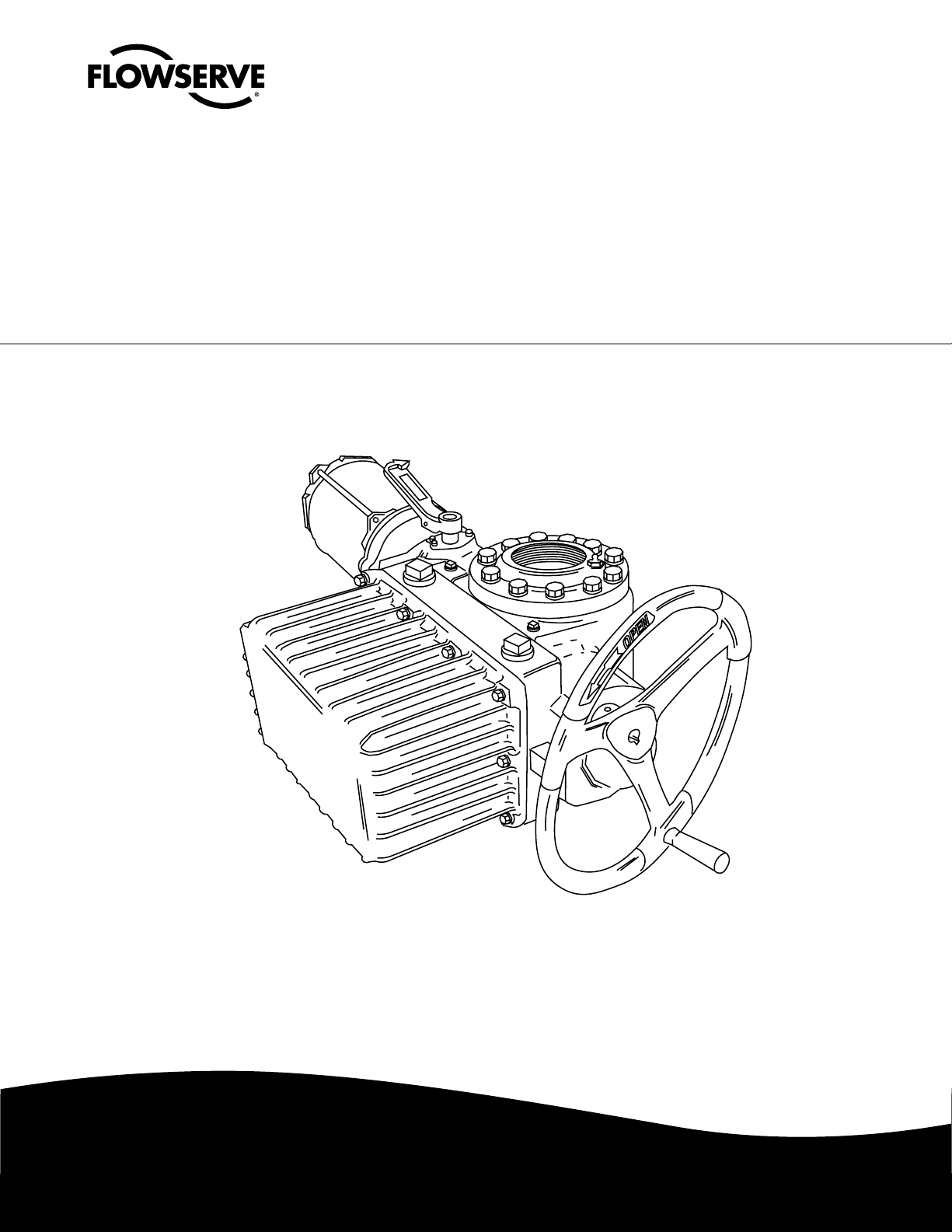
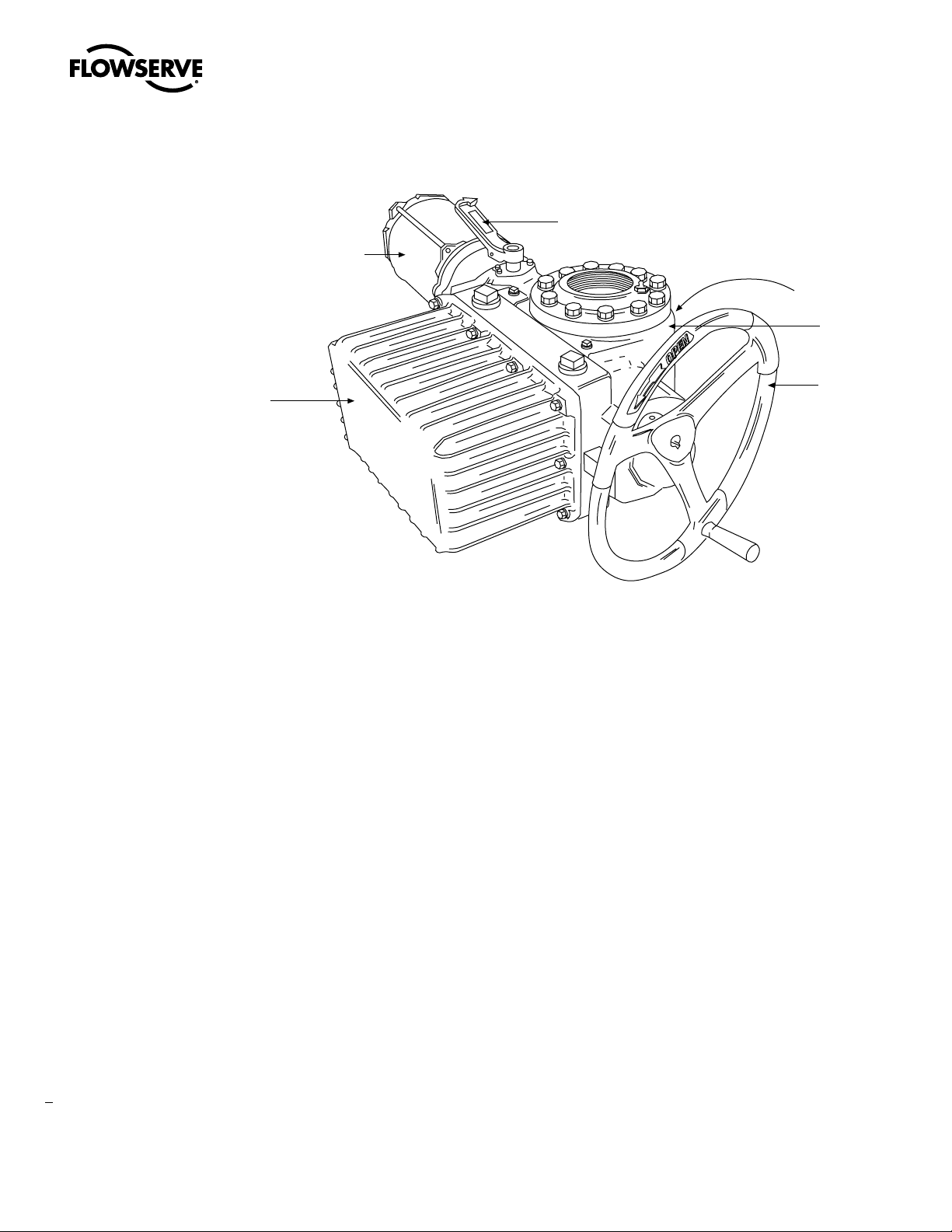
Figure 3.1 – L120-190 through 2000
Motor
Declutch
Lever
Actuator Nameplate
(hidden)
Housing
Limit Switch
and Controls
Compartment
Handwheel
3.2 Inspection and Recording
Upon receipt of the actuator, inspect the condition of the equipment and record nameplate information.
1. Carefully remove actuator from shipping carton or skid. Thoroughly examine the equipment for
any physical damage that may have occurred during shipment. If damaged, immediately report the
damage to the transport company.
2. Record the actuator nameplate information for future reference, i.e., ordering parts, obtaining
further information.
3.3 Storage Procedures
NOTE: The following are our recommended storage procedures to retain maximum product integrity
during short-term storage. Failure to comply with recommended procedures will void the warranty. For
longer-term storage, contact Limitorque for procedures and recommendations.
3.3.1 Short-Term Storage (less than 1 year)
Actuators are not weatherproof until properly installed on the valve or prepared for storage.
Store actuators in a clean, dry, protected warehouse away from excessive vibration and rapid tempera-
8
ture changes. If the actuators must be stored outside, they must be stored off the ground, high enough
to prevent them from being immersed in water or buried by snow.
Page 9

Limitorque
1. Position the actuator in storage with motor and switch compartment horizontal.
2. Connect the space heaters (if supplied) or place desiccant in the switch compartment.
3. Connect space heaters if actuator is to be stored in a damp place.
4. Replace all plastic caps or plugs with pipe plugs and ensure that all covers are tight.
5. If the actuator is mounted on a valve and the stem protrudes from the actuator, a suitable stem
cover must be provided.
®
L120-190 through L120-2000 FCD LMENIM1203-00 – 10/11
flowserve.com
9
Page 10

4
Limitorque® L120-190 through L120-2000 FCD LMENIM1203-00 – 10/11
Actuator Weights
The approximate L120 actuator weights are provided below:
Table 4.1 – Actuator Weights
Actuator Size Control Types
3
NCU
3
L120-190
L120-420
L120-800 NCU
L120-2000 NCU
Note 1: Torque Only
Note 2: Torque and Thrust
Note 3: NCU = No Controls Actuator
BIC = Basic Integral Controls
UEC = Universal Electronic Controller
BIC
UEC/Clamshell
3
NCU
3
BIC
UEC/Clamshell
3
3
Drive 1 Weight Side HW Drive 2 Weight Side HW
lb. kg lb. kg
520 192 520 192
3
3
586 217 586 217
586 217 586 217
1065 394 1065 394
1130 418 1130 418
1220 451 1220 451
1
1270
1
2500
471
925
1
1
1700
3300
2
2
629
1221
2
2
10
Page 11

5
Limitorque
®
L120-190 through L120-2000 FCD LMENIM1203-00 – 10/11
Installation Instructions
5.1 Safety Precautions
c WARNING: Read this Installation and Maintenance Manual carefully and completely before
attempting to install, operate, or troubleshoot the Limitorque actuator.
c WARNING: Be aware of electrical hazards. Turn off incoming power before working on the
actuator and before opening the switch compartment.
c WARNING: Potential HIGH PRESSURE vessel — be aware of high-pressure hazards associated
with the attached valve or other actuated device when installing or performing maintenance
on the actuator. Do not remove the actuator mounting bolts from the valve or actuated device
unless the valve or device stem is secured or there is no pressure in the line.
c WARNING: For maintenance and/or disassembly of the actuator while installed on the valve,
ensure that the actuator is not under thrust or torque load. If the valve must be left in service,
the valve stem must be locked in such a way as to prevent any movement of the valve stem.
c WARNING: Do not attempt to remove the spring cartridge cap, housing cover, or stem nut
locknut from the actuator while the valve or actuated device is under load.
c WARNING: Do not manually operate the actuator with devices other than the installed hand-
wheel and declutch lever. Using force beyond the ratings of the actuator and/or using additive
force devices such as cheater bars, wheel wrenches, pipe wrenches, or other devices on the
actuator handwheel or declutch lever may cause serious personal injury and/or damage to the
actuator and valve.
c WARNING: Do not exceed any design limitations or make modifications to this equipment
without first consulting Limitorque.
11
flowserve.com
Page 12

Limitorque® L120-190 through L120-2000 FCD LMENIM1203-00 – 10/11
c WARNING: Actuators equipped with electrical devices (motors, controls) requiring field wiring
must be wired and checked for proper operation by a qualified tradesman.
c WARNING: Use of the product must be suspended any time it fails to operate properly.
a CAUTION: Do not use oversized motor overload heaters. Instead, look for the cause of the
overload.
a CAUTION: Do not operate the valve under motor operation without first setting or checking the
limit switch setting and motor direction.
a CAUTION: Do not force the declutch lever into the motor operation position. The lever returns to
this position automatically when the motor is energized.
a CAUTION: Do not depress the declutch lever during motor operation to stop valve travel.
a CAUTION: Do not use replacement parts that are not genuine Flowserve Limitorque parts, as
serious personal injury and/or damage to the actuator and valve may result.
a CAUTION: Do not lift actuator/gearbox or actuator/valve combinations with only the eye bolts in
the L120 actuator. These eye bolts are designed for lifting the L120 actuator only.
a CAUTION: Do not lift the actuator by handwheel.
5.2 Safety Practices
The following check points should be performed to maintain safe operation of the L120 actuator:
• Eye bolts are designed for lifting only the actuator and not associated gearboxes or valves.
• Mount motor on a horizontal plane, if possible. Preferably, keep the motor or limit switch compartment from hanging down. This prevents head of grease from being against motor or switch seals.
• Keep the switch compartment clean and dry.
• Keep the valve stem clean and lubricated.
• Set up periodic operating schedules for infrequently used valves.
• Verify that all actuator wiring is in accordance with the applicable wiring diagram.
• Carefully check for correct motor rotation direction. If the motor is driving the valve in the wrong
direction, interchange any two leads on the three-phase motor or switch the armature leads on DC
motors.
• Use a protective stem cover. Check valve stem travel and clearance before mounting covers on rising
stem valves.
• Verify that a locking nut tightly secures the stem nut and that the top thread of the lock nut is crimped
and staked in two places.
• For the DC motor, keep the armature clean and periodically check brushes for proper contact and wear.
12
5.3 Actuator Preparation
NOTE: Replace all molded plastic conduit and top protectors (installed for shipping purposes only) with
pipe plugs when installation wiring is complete.
Page 13
Limitorque
OPEN
®
L120-190 through L120-2000 FCD LMENIM1203-00 – 10/11
5.3.1 Mounting Base
The mounting hole sizes and quantities are as detailed in Table 5.1, below:
Table 5.1 – Mounting Base Dimensions
Actuator Size
L120-190 8 ¾–10 x 1.13 M20 x 2.5 x 32 11.75 298 mm
L120-420 8
L120-800 (Torque Only) 8 ¾–10 x 1.63 N/A 17.0 N/A
L120-800 (Thrust Only) 8 1.25–7 x 2.0 N/A 16 N/A
Mounting Holes Tap Size
Quantity MSS MSS
7
⁄8–9 x 1.75 N/A 14.0 N/A
ISO
Bolt Circle
ISO
L120-2000 (Torque Only)
L120-2000 (Thrust Only) 12 1-½–6 x 3.0 N/A 18.0 N/A
16
1–8 x 2.0 N/A 23.5 N/A
5.3.2 Stem Acceptance
The maximum stem acceptance is provided in Table 5.2, below:
Table 5.2 – Maximum Stem Acceptance
Actuator size
L120-190 3.5 89 2.875 73 ¾ x ¼ 20 x 12
L120-420 5 127 4.25 108 1 x ¾ 28 x 16
L120-800 5 127 7 178 1 x ¾ 32 x 18
L120-2000 6.25 159 8.00 203 1¼ x
NOTE: For complete mounting dimensions, see sales brochure LMENBR1200.
Drive 2 Tapped Drive 1 Bore Drive 1 Key
inch mm inch mm inch mm
7
⁄8 40 x 22
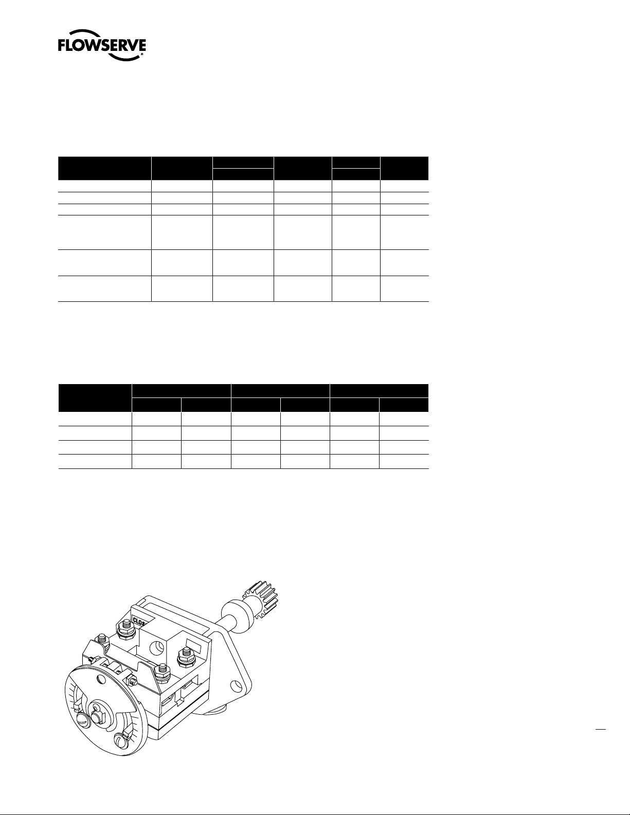
5.4 Double Torque Switch
The torque switch is designed to protect the actuator in open and close directions.
Figure 5.1 – Double Torque Switch
NOTE: See Caution and Note on following page.
13
flowserve.com
Page 14

Limitorque® L120-190 through L120-2000 FCD LMENIM1203-00 – 10/11
a CAUTION: Disconnect all incoming power before opening limit switch compartment or working
on the torque switch.
• Do not use abrasive cloth to clean the contacts on the torque switch.
• Do not torque-seat 90° operation valves or run them against the stops. This may cause damage
to the valve.
NOTE: If the actuator has “torqued out,” release torque buildup by operating the actuator manually in
opposite direction ½ to 1 turn of the output drive sleeve.
NOTE: Torque switch contacts are rated 600 volts, in accordance with NEMA ICS-2.
5.4.1 Setting Torque Switch
The torque switch was set at the factory according to customer-supplied information regarding necessary torque or thrust output provided at the time of the order. However, if the torque switch is newly
installed or the setting needs to be adjusted, follow the procedure below:
a CAUTION: A maximum stop setting plate is provided on most actuators. Do not remove this
plate. Do not exceed the setting indicated by this plate without contacting Limitorque.
• Installing or adjusting the torque switch with the operator in a “loaded” condition will result in a
loss of torque protection.
Item letters correspond to Figure 5.2.
1. Place the L120 actuator in manual mode.
2. Release the load on the wormshaft spring pack. Put operator in manual mode and operate in
opposite direction until switch is in neutral position.
3. For open and close directions, loosen Screw (A) and move Pointer (B) to desired position. A higher
number indicates a high torque and/or thrust output.
4. Tighten Screw (A).
5. Operate the valve electrically to seat the valve and to ensure tight shutoff.
Figure 5.2 – Setting Torque Switch
Maximum Stop
Setting Plate
14
B
Torque Switch Dial
A
Page 15

Limitorque
A
®
L120-190 through L120-2000 FCD LMENIM1203-00 – 10/11
5.4.2 Balancing Torque Switch
Item letters correspond to Figure 5.2.
1. Place the actuator in manual mode.
2. Remove the load from the wormshaft spring pack.
NOTE: If the actuator has “torqued out,” release torque buildup by operating the actuator manually in
opposite direction ½ to 1 turn.
3. Note the open and close torque switch settings prior to re-installing the torque switch.
4. Loosen Screws (A) and position both Pointers (B) at the #1 setting; tighten Screws (A).
5. Mount the torque switch and tighten the mounting screws. Verify that both contact pointers are
touching the arms. The interface between the pointers and the arm is found beneath the torque
switch dial. If the pointers and the arms are not in contact, the clearance on the open and close
torque switches should be equal. If not equal, the torque switch needs to be balanced. (See Step 7.)
6. If the pointers and arms are in contact on both sides of the switch, manually rotate the torque
switch dial clockwise and counter-clockwise to determine if there is equal backlash in both directions of rotation. If there is not equal backlash in both directions, the torque switch needs to be
balanced. (See Step 7.)
7. Loosen both hex nuts.
8. Back out one setscrew and tighten the other setscrew until there is equal backlash in both directions
of rotation of the dial, or equal clearance between the pointers and arms.
9. Tighten the hex nuts and return the torque switch to its original settings.
a CAUTION: The balancing screws should not be touched except during the balancing procedure.
The switch is now balanced and ready for the pointers to be returned to their original settings.
5.4.3 Torque Switch Terminal Connections
Wiring connections to the L120 geared limit switch, torque switch, and marathon terminal strips are to
be made using ring-tongue terminals as shown below:
Figure 5.3 – Ring Tongue Terminal
C
B
See Table 5.3, next page
15
flowserve.com
Page 16

Limitorque® L120-190 through L120-2000 FCD LMENIM1203-00 – 10/11
Table 5.3 – Terminal Dimensions By Cable Size
AWG Screw Hole Insulation
22-16 #10 Vinyl 18RA-10 .97 .31 .27
18-14 #10 Vinyl 14RB-10 .97 .31 .27
12-10 #10 Vinyl 14RC-10 1.06 .31 .27
Terminals are to be crimped using Thomas & Betts crimping tool WT111M.
Thomas &
Betts P/N
A B C
5.5 Geared Limit Switch – Rotor Type
a CAUTION: The geared limit switch is not preset at the factory and must be adjusted after the
actuator has been mounted on associated equipment.
NOTE: Limit switch contacts are rated 600 volts, in accordance with NEMA ICS-2
• Disconnect all incoming power to the actuator prior to opening the limit switch compartment and
adjusting the switch.
• Consult the relevant wiring diagram for limit switch contact development. All L120 actuators are
supplied with 16-contact limit switches - four switches on each of the four rotors. Two rotors are
used for end-of-travel indication. The remaining two rotors may be adjusted for any intermediate
point-of-travel.
• Do not use abrasive cloth to clean the contacts on the limit switch.
• Do not attempt to repair gearing in the limit switch. Replace entire gear frame assembly if necessary.
16
5.5.1 Setting Limit Switch
The maximum number of drive sleeve turns available is a funtion of actuator size, worm gear ratio,
and type of switch. See Table 5.4. The Intermediate Shaft shown in Figure 5.5 may take a considerable
number of turns before rotor trip occurs.
c WARNING: Potential Explosion Hazard. Do not use a variable speed electric drill for setting the
limit switch in an explosive environment.
a CAUTION: When setting the limit switch rotor segments (cams) using a variable speed electric
drill, do not run drill at speeds higher than 200 RPM. Operating the drill at high speeds can
damage the gearing within the limit switch.
Page 17
Limitorque
®
L120-190 through L120-2000 FCD LMENIM1203-00 – 10/11
Table 5.4 – Maximum Drive Sleeve Turns
Limit Switch Gearing PIC Gearing
Actuator Size W.G. Ratio 4-Gear 5-Gear PIC or R/I (270) RVDT(90)
L120-190 13.3:1 3110 31100 13706 4569
33:1 1250 12500 5521 1837
60:1 690 6900 3037 1012
85:1 N/A N/A N/A N/A
L120-420 10.33:1 N/A N/A N/A N/A
16:1 3300 33000 11405 3797
41:1 1280 12800 4445 1481
57:1 910 9100 3195 1065
80:1 N/A N/A N/A N/A
L120-800 12.67:1 N/A N/A N/A N/A
19:1 2850 28500 9586 3195
49:1 1050 10500 3720 1240
58:1 N/A N/A N/A N/A
86:1 N/A N/A N/A N/A
L120-2000 43:1 1210 12100 4234 1413
71:1 740 7400 2566 855
Figure 5.4 – Geared Limit Switch
Set the limit switch as shown on the following page. All item letters and piece numbers refer to Figure 5.5.
flowserve.com
17
Page 18

Limitorque® L120-190 through L120-2000 FCD LMENIM1203-00 – 10/11
Assembly
Figure 5.5 – Setting Geared Limit Switch
Contact Plunger
Rotor Cam
Intermediate Shaft
Contact Open
8
7
Contact Close
3
Clutch
Screw
4
9
2
A
Close
Open
B
Clutch Screw
5
Piece Quantity Description
C
INT - 1 INT - 2
D
1 1 Gear Frame Assembly
6
2 2 8-Switch Contact Block
3 12 Rotor Segment (short)
4 4 Rotor Shaft
5 4 Machine Screw
6 4 Flat Washer
7 4 Lock Washer
8 8 Hex Nut
9 4 Rotor Segments (long)
18
1
Unless otherwise noted part numbers refer to Figure 5.5.
1. Open the Limit Switch Compartment Cover (piece #200-1 of Figure 8.3 for L120-190 and -420,
Figure 8.6 for L120-800, and Figure 8.7 for L120-2000).
2. Put the actuator into manual operation. Use the handwheel to operate the valve in the “open”
direction. While operating the valve, note the direction of rotation of the Intermediate Shaft
corresponding to the rotor or rotors to be set.
3. When the valve is fully open, close it one turn of the handwheel to allow for coast of moving parts.
4. Push in the Clutch Screw and turn one-quarter turn. The rod will latch in this depressed position.
5. Refer to the applicable wiring diagram for contact development. The limit switch contact is closed
when the rotor is engaged with the plunger. If the rotor to be set has not turned 90° to operate
the plunger, turn the intermediate shaft in the same direction as noted in Step No. 2 until the rotor
clearly trips the switches. This rotor is now set correctly.
6. If the intermediate position rotors 1 and 2 are also to be set at any desired position, repeat the
setting operation in steps 1 through 5 above.
7. Before moving the valve, depress and turn the Clutch Screw counterclockwise one-quarter turn to
the spring-released position. Insert a screwdriver into the intermediate shafts to ensure that they are
loaded in position and will not rotate.
Page 19

Limitorque
®
L120-190 through L120-2000 FCD LMENIM1203-00 – 10/11
NOTE: The cross-slotted shafts A, B, C, and D have been designed for use with a No. 2 Phillips
screwdriver shank chucked into a variable speed reversible electrical drill. Do not run drill at speeds
higher than 200 RPM (see previous CAUTION on page 16).
a CAUTION: Do not operate the valve when the Clutch Screw is in a fully depressed position. Loss
of contact setting will occur and the setting rod will be damaged.
8. Operate the valve by handwheel to the fully “close” position; reverse direction by one turn of the
handwheel to allow for coast of moving parts.
9. Set the other rotors by following steps 1 through 7.
10. Secure the Limit Switch Compartment Cover (piece #200-1 of Figure 8.3 for L120-190 and -420,
Figure 8.6 for L120-800, and Figure 8.7 for L120-2000).
NOTE: For actuators having captive bolts, pull-down torque must not exceed 30 ft lbs.
5.5.2 Combination of Contacts
Refer to Figure 5.5.
The rotor segments can be separated and rotated through 90° to give various combinations of normally
open or normally closed contacts to each rotor.
1. Remove Nuts (piece #8) and Fillister Head Machine Screws (piece #5) for a total of two fasteners on
each side of the switch.
2. Remove complete contact assembly from the back plate.
3. Rearrange cams on the camshaft to produce the required combination of contacts.
4. Replace contact assembly on back-plate (ensuring the registers fit correctly) and secure with the
machine screws and nuts.
5.6 Position Indication
5.6.1 Local Position Indication
The local dial position indicator is factory-built per the application. The position indicator can only be
adjusted when mounted on the valve.
Figure 5.6 – Position Indicators
MID-TRAVEL
CLOSE
OPEN
50
25
75
0
PERCENT
O PEN
100
NOTE: See the setting procedure on the following page.
19
flowserve.com
Page 20

Limitorque® L120-190 through L120-2000 FCD LMENIM1203-00 – 10/11
1000 ohms
To set the local position indicator:
1. Disconnect all incoming power and remove Limit Switch Compartment Cover (piece #200-1 of
Figure 8.3 for L120-190, -420 and -800, and Figure 8.7 for L120-2000).
2. Using the handwheel place the valve in the fully “close” position.
3. Loosen the round head machine screw which holds the pointer in place; move the pointer to the “O”
position, and re-tighten the screw.
The indicator is now set.
NOTE: The end-of-travel rotors of the geared limit switch activate “flip-flop” type indicators. This type of
indicator will require no further setting after the geared limit switch has been adjusted.
5.6.2 Remote Position Indication
The remote position indicator is a Limitorque digital position indicator. This indicator is a digital LED
display module that displays valve position in 1% increments. The readout accepts inputs from signals
of 4-20 mA, 0-2 V, or a 1000 ohm feedback potentiometer (mounted on the MDPI). The readout is
accurate to 1% +/- 1 digit.
5.6.3 Calibrating Position Transmitter PT20SD
1. Position the actuator to mid-travel value at 50% position.
2. Disconnect the potentiometer wiring harness from the PT20SD board and measure the resistance
from each end connection to the center connection on the potentiometer.
3. Set the potentiometer to the correct resistance reading. Loosen the setscrew that retains the spur
gear on the potentiometer shaft and rotate the shaft until a reading of 500 ohms is achieved.
4. Tighten the setscrew and reconnect the wiring harness to the PT20SD.
5. Run the actuator fully CLOSED.
6. Calibrate ZERO position by adjusting the zero potentiometer until a 4mA output signal is read at
terminal +Ve and -Ve.
7. Run the actuator fully OPEN.
8. Calibrate SPAN position by adjusting the span potentiometer until a 20mA output signal is read at
terminals +Ve and -Ve.
9. Repeat steps 5 through 8 and fine-tune as necessary.
Figure 5.7 – Typical Connection for a 1000 ohm Potentiometer
20
Gearing
Receiver
+
-
Customer Equipment
DC Power
Suppl y
-
+
Page 21

6
Limitorque
Operation
®
L120-190 through L120-2000 FCD LMENIM1203-00 – 10/11
c WARNING: See Sections 5.1 and 5.2 Safety Precautions and Safety Practices.
c WARNING: Do not manually operate the actuator with devices other than the installed
Handwheel and Declutch Lever. Using force beyond the ratings of the actuator and/or using
additive force devices such as cheater bars, wheel wrenches, pipe wrenches or other devices on
the actuator Handwheel or Declutch Lever may cause serious personal injury and/or damage to
the actuator or valve.
a CAUTION: Do not motor-operate the valve without first setting or checking the limit switch
setting and motor direction. If the valve closes when the open button is pushed, the motor may
need to be electrically reversed.
• Do not force the declutch lever into hand operation. If the clutch does not easily engage, rotate
handwheel slowly while operating the declutch lever.
• Do not force the declutch lever into motor operation position. Lever returns to this position automatically when motor is energized.
• Do not run “plug” type valve against stop.
• Do not alternately start/stop the motor to open or close a valve that is too tight for normal operation.
6.1 Electrical Start-Up
1. Verify that the actuator has been correctly lubricated. This is particularly important if the actuator
has been in long-term storage.
2. Verify that the geared limit switch has been correctly set per Section 5.5.1, Setting Limit Switch.
3. If the valve stem is not visible, remove the stem cover or handwheel cover plate to observe the
output direction of the drive sleeve.
4. Engage manual operation and hand crank the valve well away from end-of-travel positions.
5. Turn on power supply and push the “open” button on the pushbutton station.
21
flowserve.com
Page 22

Limitorque® L120-190 through L120-2000 FCD LMENIM1203-00 – 10/11
6. Check output rotation:
• If phase rotation is correct, the valve should begin to open.
• If valve begins to CLOSE, STOP IMMEDIATELY. Incorrect phase rotation will lead to serious
damage if the valve seats.
NOTE: For UEC only – if incorrect rotation, select opposite direction with dipswitch.
7. Correct the phase rotation one of two ways:
• switch any two of the three power leads for three-phase power, or
• reverse the armature leads for DC power.
The actuator should operate correctly and will be stopped at the end-of-travel positions by torque or
limit switch functions.
Premature stopping may be caused by incorrect limit switch or torque switch settings or obstructions in
the valve.
6.1.1 Typical Wiring Diagram
Figures 9.1 through 9.4 are representations of typical applications and may not be applicable to
your specific actuator. Please refer to the wiring diagram supplied with your actuator to confirm the
actual equipment supplied. Check www.limitorque.com for the latest diagram revisions and/or related
diagrams.
22
6.2 Manual Operation
Piece numbers refer to Figures 8.1, 8.2, and 8.3 for L120-190 and -420, Figures 8.4, 8.5, and 8.6 for
L120-800, and Figures 8.7 - 8.10 for L120-2000.
The actuator has a handwheel for manual operation. The actuator may be manually operated any time
the motor is not engaged.
Manually operate as follows:
1. Move the Declutch Lever (piece #10, #11) in the direction of the arrow until it latches into place. Do
not force the lever.
2. If the lever will not latch, rotate the Handwheel (piece #5) while turning the declutch lever and the
lever will latch in place.
When the declutch lever is turned, it rotates a Cam which causes the Clutch Fork (piece #42-1) to move
the Worm Shaft Clutch (piece #33) axially along the worm shaft against the force of a Clutch Spring
(piece #45, #46). This disengages the mating lugs on the Worm Shaft Gear (piece #32) and the clutch,
and engages the clutch with the Handwheel Gear (piece #17, #9). The Clutch Trippers (piece # 34-A
and 34-B) maintain this position and latch onto the worm shaft gear. Turning the Handwheel (piece #5)
rotates the Handwheel Shaft (piece #18) and the Handwheel Pinion. The handwheel pinion then drives
the Handwheel Gear (piece #8, #9) which in turn drives the clutch. The clutch then drives the actuator in
the same manner as in motor operation.
When the motor is energized, the motor pinion will turn the worm shaft gear. Tripper cams mounted
on the worm shaft gear cause the trippers to release the clutch. The Clutch Fork (piece #42-1) is then
forced, under spring pressure, to return the clutch to the motor operation position.
NOTE: The shift from manual operation to motor operation is automatic and does not require external
positioning of the declutch shaft.
Page 23

Limitorque
®
L120-190 through L120-2000 FCD LMENIM1203-00 – 10/11
6.3 Motor Operation
The actuator is always available for motor operation whenever the motor is energized.
a CAUTION: Do not force the declutch lever into motor operation. Lever will automatically return
to motor operation when the motor is energized.
Reset the travel limit switches prior to motor operation if the actuator has been dismantled or removed
from the valve. Piece numbers refer to Figures 8.1, 8.2, and 8.3 for L120-190 and -420, and Figures 8.4,
8.5, and 8.6 for L120-800.
In motor operation, the Motor Pinion (piece #31) drives the Worm Shaft Gear (piece #32), which drives
the Worm Shaft Clutch (piece #33) through the clutch lugs on both the worm shaft gear and the clutch.
The Worm Shaft (piece #17) is driven by splines on the OD of the worm shaft and on the ID of the
clutch. The worm shaft is splined to the Worm (piece #30-1) which drives the Worm Gear (piece #13).
Two lugs on the worm gear are engaged by matching grooves in the Drive Sleeve (piece #8). This
arrangement provides the no-lost-motion mode of operation and allows the worm gear to turn the
drive sleeve. The worm gear lugs may also be oriented outside the grooves to give the lost-motion
or hammerblow effect. The Stem Nut (piece #12) is rotated by internal splines on the ID of the drive
sleeve and external splines on the OD of the stem nut. This causes a threaded stem to translate in a
threaded stem nut and a keyed shaft to rotate in a keyed stem nut. Thrust is absorbed by Bearings
(piece #40, #41, #14, and #67 ) located at the top and bottom of the drive sleeve.
6.4 Torque and Travel Limiting
Unless otherwise stated, piece numbers refer to Figures 8.1, 8.2, and 8.3 for L120-190 and -420, and
Figures 8.4, 8.5, and 8.6 for L120-800.
The Geared Limit Switch (piece #305 of Figure 8.6) is driven directly by the worm shaft gear through the
limit switch pinion. Thus, the limit switch is directly connected to the output of the actuator and, once
properly set, remains in step with the valve position regardless of the electric or manual operation of the
actuator.
As the actuator increases torque, the worm and the Torque Spring Cartridge Assembly
(composed of piece #'s 16-1 through 16-8) move axially along the worm shaft, compressing the disk
spring packs. The torque spring assembly is calibrated such that a finite spring compression relates to
a finite output torque. Axial worm movement causes movement of the bearing cartridge that is geared
to the Torque Switch (piece #300). The torque switch is graduated and adjustable so it may be set to
interrupt power to the motor at a predetermined output torque level.
flowserve.com
23
Page 24

7
Limitorque® L120-190 through L120-2000 FCD LMENIM1203-00 – 10/11
Maintenance
7.1 Lubrication
The L120 series actuators have a totally sealed gear case, factory-lubricated with grease. The gear case
can be mounted in any position.
a CAUTION: When the actuator is mounted in an upside-down orientation, the worm may not be
completely immersed in lubricant. Check lubricant levels before operating the actuator.
No seal can remain absolutely tight at all times. Therefore, it is not unusual to find a very small amount
of weeping around shaft seals—especially during long periods of idleness such as storage. Using
grease minimizes this condition as much as possible. If a small amount of lubricant is weeping at
start-up, remove it with a clean cloth. Once the equipment is operating on a regular basis, the weeping
should stop.
7.1.1 Lubrication Inspection
Inspect Limitorque L120 series actuators for correct lubrication prior to operating—particularly
following a long storage period.
Each application has its own effect on the actuator. The frequency of these inspections should be based
on the application and the operating experience. The following lubrication inspection schedule is recommended until operating experience indicates otherwise.
For Gear Case, inspect lubrication every 18 months or 500 cycles, whichever occurs first.
24
During an inspection, consider the following:
• Quantity – Ensure there is enough lubricant so that the Worm and the Worm Gear are totally
immersed in grease regardless of the position.
• Quality – Inspect lubricant for dirt, water or other foreign matter. If any one of these is found:
1. Flush the actuator with a commercial degreaser/cleaner such as Exxon Varsol #18. This
degreaser/cleaner is not corrosive and does not affect the seal materials.
2. Repack the actuator with fresh lubricant, allowing room for grease thermal expansion.
Page 25

Limitorque
• Consistency – Ensure the lubricant is fluid approximating a standard NLGI-0 grade consistency or
less. Thinners such as Amoco WAYTAC #31 oil may be added provided the volume of thinner does
not exceed 20% of the total lubricant.
®
L120-190 through L120-2000 FCD LMENIM1203-00 – 10/11
7.1.2 Factory Lubricant
Gear Case
• The L120-190 through 2000 is factory-lubricated with an NLGI Grade 00 lithium-base grease, suitable
for temperatures from 0°F to 225°F (-18°C to 107°C).
Geared Limit Switch
• Mobil 28 (No Substitute)
Table 7.1 – Lubricant Weights
Actuator Size lb. kg
L120-190 15 5.6
L120-420 50 18.7
L120-800 Drive 1 71 26.5
L120-800 Drive 2 75 28
L120-2000 Drive 1 65 24.3
L120-2000 Drive 2 72 26.9
Minimum Lubricant Qualities Required
The standard lubricants used by Limitorque have been proven to be extremely reliable over years of
service. Limitorque does not recommend a particular lubricant substitute for the standard lubricants;
however, Limitorque does require the following lubricant qualities as a minimum.
a CAUTION: Do not mix lubricants of a different base chemical. Mixing lubricant bases may cause
lubricant properties to be ineffective.
The lubricant must:
• Contain an “EP” additive.
• Be suitable for the temperature range intended.
• Be water and heat-resistant and non-separating.
• Not create more than 8% swell in Buna N or Viton.
• Not contain any grit, abrasive, or fillers.
• Comply with a slump-prefer NLGI-00 grade.
• Not be corrosive to steel gears, ball, or roller bearings.
• Have a dropping point above 316°F (158°C) for temperature ranges of 0°F to 225°F (-18°C to 107°C).
flowserve.com
25
Page 26

8
Limitorque® L120-190 through L120-2000 FCD LMENIM1203-00 – 10/11
Disassembly and Reassembly
c WARNING: See sections 5.1 and 5.2 Safety Precautions and Safety Practices prior to
disassembly.
c WARNING: Potential High Pressure Vessel. Before removing or disassembling your actuator,
ensure that the valve or other actuated device is isolated and is not under pressure.
a CAUTION: Turn off all power services before attempting to perform service on the actuator.
NOTE: Remove the actuator from the valve for complex work. Minor work, such as replacing geared
limit switch, torque switch or motor, may be readily performed while the actuator is still on the valve.
8.1 L120-190, -420, and -800
c WARNING: See sections 5.1 and 5.2 Safety Precautions and Safety Practices prior to
disassembly.
NOTE: The disassembly of the actuator L120–190 will be used as a general example. Always refer
to the parts drawing when disassembling. Be certain to keep all parts clean and free from dirt after
disassembly.
NOTE: Unless otherwise noted, piece numbers refer to Figures 8.1, 8.2 and 8.3 for L120-190 and -420,
and Figures 8.4, 8.5 and 8.6 for L120-800.
26
8.1.1 To Replace Stem Nut Only
c WARNING: Do not remove Locknut (piece #39) with actuator under load or with valve under
pressure. See Warning on Step No. 11 of Section 8.1.2 L120-190, 420, 800 Disassembly.
NOTE: If the valve must be left in service while the stem nut is replaced, the valve stem must be locked
in such a way as to prevent any movement of the valve stem.
Page 27

Limitorque
Piece numbers refer to Figures 8.1, 8.2 and 8.3 for L120-190 and -420, and Figures 8.4, 8.5 and 8.6 for L120-800.
If the Stem Nut (piece #12) is to be removed from the assembled actuator, remove the Lock Nut (piece #39) and
lift out top of nut.
1. The Lock Nut (piece #39) is staked in two places. Locate the stakes and spot with a drill.
2. Clean all metal particles and remove.
3. If the actuator is mounted on a valve having a threaded stem, and removal of the stem nut is required,
perform Step No.1 and rotate the handwheel to close the valve.
4. The stem nut will rise up the threaded valve stem. When the stem nut splines are free from the drive sleeve,
rotate the stem nut by hand the remaining length of the valve stem.
5. Replace if necessary.
6. Install the new stem nut with the lock nut.
7. Stake the top threads of the lock nut in two places.
®
L120-190 through L120-2000 FCD LMENIM1203-00 – 10/11
8.1.2 L120-190, 420, 800 Disassembly
Piece numbers refer to Figures 8.1, 8.2 and 8.3 for L120-190 and -420, and Figures 8.4, 8.5 and 8.6 for L120-800.
1. Turn off power to the actuator.
2. Open or remove electrical Compartment Cover (piece #200-1).
3. Disconnect all electrical leads from the Torque Switch (piece #300) and Geared Limit Switch (piece #305).
Ensure that all leads and terminals are clearly marked to facilitate reassembly.
4. Remove two screws holding limit switch and one holding torque switch. Remove both items.
5. Remove four bolts holding Motor (piece #124) and three bolts holding conduit Nipple Flange (piece #26).
Remove motor, drawing motor leads through the conduit opening.
6. Replace Motor Pinion (piece #31). The motor pinion is keyed to the motor shaft and held there with a
setscrew and lockwire to retain the pinion in its proper position. The motor pinion should be shouldered on
the motor shaft.
7. Remove Handwheel (piece #5) by loosening setscrew. Handwheel can then be pulled from Handwheel Shaft
(piece #18).
8. Remove Declutch Lever Subassembly (piece #11) by removing Extension Spring (piece #48), Retaining Ring
(piece #53-4), Declutch Link (piece #10), and two hex head cap screws holding the subassembly in place.
Remove subassembly.
9. Remove Spring Cartridge Cap (piece #4).
10. Remove Worm and Torque Spring Subassembly (piece #13, #30-1) completely. Temporarily replace the
handwheel and then rotate in the close direction to cause the worm to screw out of engagement with worm
gear and cause the torque spring cartridge to emerge from Housing (piece #1). See Step No. 21 to further
disassemble the cartridge.
11. Remove Housing Cover (piece #3).
c WARNING: Do not remove if a thrust load is on the actuator or if the valve is under pressure and not fully
open, as personal injury may result.
27
flowserve.com
Page 28

Limitorque® L120-190 through L120-2000 FCD LMENIM1203-00 – 10/11
12. Lift complete drive sleeve assembly from actuator housing. The drive sleeve assembly consists
of Lock Nut (piece #39), Stem Nut (piece #12), Drive Sleeve (piece #8), Upper Thrust Bearings
(piece #40, #67), Worm Gear (piece #13), Worm Gear Spacer (piece #36) and Lower Thrust Bearing
(piece #14). The drive sleeve assembly may be further dismantled if required by pressing off Lower
Drive Sleeve Bearing (piece #41).
13. Remove Retaining Ring (piece #53-1), Split Ring Retainer (piece #27) and Conduit Nipple
(piece #26). Pull the Worm Shaft Clutch Gear (piece #32) from the worm shaft.
14. Spread clutch trippers with a tool to shift actuator into motor operation.
c WARNING: Do not use hands as spring forces could result in personal injury.
15. Remove bolts holding Declutch Housing (piece #2) to Housing (piece #1). Remove clutch housing,
Trippers (piece #34-A and #34-B), and Clutch Fork Assembly (piece #42-1). Worm Shaft Clutch
(piece #33) will slide off worm shaft when removing clutch housing.
16. Slide Clutch Spring (piece #45) off worm shaft toward motor end.
17. Remove Elastic Stop Nut (piece #16-7). Pull Handwheel Spur Gear (piece #9) that is keyed to Shaft
(piece #17).
18. Remove bolts holding WS Bearing Cap (piece #7) and slide cap off wormshaft. Remove Handwheel
Clutch Pinion (piece #20) from bearing cap by removing Retaining Ring (piece #53-3). Be careful
not to lose Handwheel Pinion Spring (piece #47) and Spring Ring (piece #49).
19. Remove Handwheel shaft: tap on the motor end of the shaft to free Ball Bearing (piece #52-1) from
housing. Handwheel shaft will break free from Ball Bearing (piece #52-6). Remove handwheel shaft
from housing.
20. Withdraw handwheel shaft from handwheel end of housing.
21. To disassemble worm assembly further (removed in Step No. 10), remove Elastic Stop Nut
(piece #16-7), noting the number of turns to remove.
22. Remove Thrust Washers (piece #16-2), Limit Sleeve (piece #16-5), and Belleville Disc Springs
(piece #16-3 and #16-4). Note the orientation of the discs for reassembly later.
23. Remove Retaining Ring (piece #53-4).
24. The Bearing Cartridge (piece #16-1) and Worm Subassembly (piece #30-1) can now be withdrawn.
25. Remove the Ball Bearing (piece #52-7), locate setscrew in bearing locknut and remove setscrew
and Locknut (piece #44-1).
8.1.3 Reassembling Actuator Sizes L120-190, -420 and -800
1. Follow the disassembly instruction for Actuator Sizes 190, 420, and 800 in the reverse order and
follow the gasketing instructions below.
28
2. Stack Belleville disc, thrust washers, and spacers that were removed in the exact order as they were
removed.
3. Re-install Elastic Stop Nut (piece #16-7) with the same number of turns used to remove.
4. For the Worm Shaft Clutch (piece #33), install the clutch with smaller set of lugs first to engage with
lugs on Handwheel Clutch Pinion (piece #20).
Page 29

Limitorque
5. For worm, rotate Worm Shaft Clutch (piece #33) to engage splines on worm shaft. Place actuator
in manual operation, replace Declutch Lever Subassembly (piece #11), and handwheel temporarily;
rotate handwheel in opposite direction used to remove worm.
6. When re-installing the Motor Pinion (piece #31), ensure it fits tightly on the motor shaft (preferably
a light press fit).
®
L120-190 through L120-2000 FCD LMENIM1203-00 – 10/11
8.1.4 Gaskets
All gaskets, except the housing cover gaskets, are 1⁄32" thick Anchorite. The housing cover gaskets
vary in thickness. Determine the correct size as follows:
1. Clean both housing cover and main housing gasketed surface.
2. Install actuator drive sleeve assembly complete with bearings.
3. Install housing cover and measure the gap between the housing cover and the main housing.
4. Add 10% to the measurement. Use the closest nominal gasket thickness or combination available.
flowserve.com
29
Page 30

Limitorque® L120-190 through L120-2000 FCD LMENIM1203-00 – 10/11
Figure 8.1 – L120-190 and -420 Drive Sleeve Side View (Refer to Table 8.1 for parts list)
61 60
61-1
64 66
63 65
55-1
3 56-3
39
54-4
55-2
55-5
38
1 54-3 12
55-11
30
37
40
67
8
54-7
Drawing 01-608-0115-4
13
364114
Page 31

Limitorque
®
L120-190 through L120-2000 FCD LMENIM1203-00 – 10/11
Figure 8.2 – L120-190-and 420 Worm Shaft Side View (Refer to Table 8.1 for parts list)
58 48 56-5 31 55-10
56-13 11 56-7 19 10 42-1
54-9 50 56-6 56-18 56-8 54-1 55-9
55-6
55-7
43 54-8
53-4
56-12
56-10
46 57
56-14
29
9
52-6
52-1
56-9 54-6 53-753-8 18
54-2 16-3 16-2 16-5 16-1 52-7 53-252-8 35 20 47 49 45 33 2 51 27 32 23 28 53-11730-130-2
55-3
4
53-5
44-2
55-4 16-7 16-6 16-4 44-1 56-15 53-3 54-1 52-3 56-11 52-37
5
Drawing 01-608-0116-4
182
31
flowserve.com
Page 32

Limitorque® L120-190 through L120-2000 FCD LMENIM1203-00 – 10/11
124
34-A
42-5
42-4
56-21
56-20
56-23
54-5
200-2
200-3
300
204
310
305
34-B 15
56-19
26
70-1
70
71
70-2
200-1
Drawing 01-608-0117-4
Figure 8.3 – L120-190 and -420 Top View (Refer to Table 8.1 for parts list)
32
Page 33

Limitorque
Figure 8.4 – L120-800 Drive Sleeve Side View (Refer to Table 8.1 for parts list)
®
L120-190 through L120-2000 FCD LMENIM1203-00 – 10/11
1 54-3 8 12 14
3
56-3
54-7
Drawing 01-608-0138-4
40
13
54-4
33
flowserve.com
Page 34

Limitorque® L120-190 through L120-2000 FCD LMENIM1203-00 – 10/11
55-7
Figure 8.5 – L120-800 Worm Shaft Side View (Refer to Table 8.1 for parts list)
56-5
10
48
56-6
115055-8
56-20
54-1
55-9
55-10
58
56-11
31
56-8
28
53-1
23
32 51 52-3
52-3
2
45 33
56-13 54-9 42-1 34
19 56-7 54-1
54-8
43
55-6
53-4
29
56-12
56-2
9
34
52-6 56-15
53-7 69
1 18 56-10
16-2 16-3 16-1 44-1 16-8 30-1 52-8 7 47 49 20
56-9 54-6 52-1 54-2
44-2 16-5 16-2 44-2 52-7 30-2 17 56-15 53-3
4 44-1
5
56-14
182
Drawing 01-608-0136-4
Page 35

Limitorque
Figure 8.6 – L120-800 Top View (Refer to Table 8.1 for parts list)
55-3
55-4
®
L120-190 through L120-2000 FCD LMENIM1203-00 – 10/11
56-23
54-5
6-1
6-2
300
70
56-18
56-2156-25 56-25
56-19
34
34
42-4
42-5
26
15
70-1
68
71
70-2
35
Drawing 01-608-0137-4
flowserve.com
305 310 204 6
Page 36

36
Limitorque® L120-190 through L120-2000 FCD LMENIM1203-00 – 10/11
Table 8.1 – L120-190, -420 and -800 typical parts list
Piece No. Quantity Description Piece No. Quantity Description
1 1 Housing 38 1 Seal Retainer Plate
2 1 Declutch Housing 39 1 Lock Nut
3 1 Housing Cover 40 1 Upper Thrust Bearing Cup
4 1 Spring Cartridge Cap 41 1 Lower Thrust Bearing Cone
5 1 Handwheel 42-1 1 Declutch Fork
6 1 Limit Switch Compartment Cover (L120-800 only) 42-4 2 Fork Roller (L120-420, 800)
6-1 1 Hex Head Cap Screw (L120-800 only) 42-5 2 Fork Roller Pin (L120-420, 800)
6-2 1 Lockwasher (L120-800 only) 43 1 Declutch Lever Plate
7 1 Worm Shaft Bearing Cap (L120-420, 800) 44-1 1 Lock Nut
8 1 Drive Sleeve (2 pc) 44-2 1 Set Screw
9 1 Handwheel Spur Gear 45 1 Clutch Spring
10 1 Declutch Link 46 1 Handwheel Shaft Spacer
11 1 Declutch Lever 47 1 Handwheel Pinion Spring
12 1 Stem Nut 48 1 Extension Spring
13 1 Worm Gear 49 1 Spring Ring
14 1 Lower Thrust Bearing Cup 50 1 Declutch Lever Nameplate
15 1 Fork Pivot Pin (L120-420, 800) 51 1 Worm Shaft Gear Cam Pin
16-1 1 Bearing Cartridge 52-1 1 Ball Bearing (L120-190)
16-2 various Thrust Washer 52-1 1 Bushing (L120-420, 800)
16-3 various Belleville Spring 52-3 2 Motor Clutch Gear Bushing
16-4 various Belleville Spring 52-6 1 Ball Bearing
16-5 1 Torque Limit Sleeve 52-7 1 Ball Bearing
16-6 1 Torque Limit Sleeve 52-8 2 Ball Bearing
16-7 1 Elastic Stop Nut (L120-190 only) 53-1 1 Retaining Ring
16-8 1 Bearing Cartridge Stem (L120-420, 800) 53-2 1 Retaining Ring
17 1 Worm Shaft 53-3 1 Retaining Ring
18 1 Handwheel Shaft 53-4 1 Retaining Ring
19 1 Declutch Shaft 53-5 1 Retaining Ring
20 1 Handwheel Clutch Pinion 53-7 1 Retaining Ring
23 1 Split Ring 53-8 1 Retaining Ring (L120-190 only)
26 1 Motor Conduit Nipple 54-1 2 Declutch Housing Gasket
27 1 Split Ring Retainer 54-2 1 Spring Cartridge Cap Gasket
28 1 Lock Nut 54-3 1 Quad Ring
29 1 Worm Bushing 54-4 1 Quad Ring
30-1 1 Worm 54-5 1 O-Ring
31 1 Motor Pinion 54-6 1 O-Ring (L120-190)
32 1 Worm Shaft Gear 54-6 1 Oil Seal (L120-420, 800)
33 1 Worm Shaft Clutch 54-7 1 O-Ring (L120-190)
34-A 1 Clutch Tripper #1 54-7 1 Gasket (L120-420, 800)
34-B 1 Clutch Tripper #2 54-8 1 O-Ring
35 1 Spring Spacer 54-9 1 Chekseal
36 1 Worm Gear Spacer 55-1 12 Hex Head Cap Screw
37 1 Housing Cover Shim Set 55-2 12 Lockwasher
Page 37

Limitorque
®
L120-190 through L120-2000 FCD LMENIM1203-00 – 10/11
Table 8.1 Continued – L120-190, -420 and -800 typical parts list
Piece No. Quantity Description Piece No. Quantity Description
55-3 7 Hex Head Cap Screw 56-23 1 Pipe Plug
55-4 various Lockwasher 56-25 2 Dowel Pin (L120-420, 800)
55-5 2 Socket Head Cap Screw 57 1 O-Ring Spacer (L120-190)
55-6 various Hex Head Cap Screw (L120-190, 420) 58 1 Tripper Spring
55-7 various Lockwasher 60 1 Terminal Bracket
55-8 2 Drive Screw 61 2 Terminal Strip
55-9 4 Hex Head Cap Screw 61-1 2 Kulka Insulator Strip
55-10 4 Lockwasher 63 2 Fil HD Mach Screw
55-11 2 Lockwasher (L120-190) 64 2 Lockwasher
56-2 various Pipe Plug 65 8 RD HD Mach Screw
56-3 1 Grease Fitting 66 8 Lockwasher
56-5 1 Clevis Pin 67 1 Upper Thrust Bearing Cone
56-6 1 Key 68 2 Fork Spacer (L120-420, 800)
56-7 1 Key 69 1 Handwheel Bearing Cap (L120-420, 800)
56-8 1 Key 70 1 Hinge
56-9 1 Socket Head Set Screw 70-1 various Hex Head Cap Screw
56-10 1 Key 70-2 various Lockwasher
56-11 1 Flat Washer (L120-190) 71 1 Hinge Standard Compartment
56-11 1 Socket Head Set Screw (L120-420, 800) 124 1 Motor
56-12 1 Flat Washer 182 1 Handwheel Spinner Kit
56-13 1 Socket Head Set Screw 200-1 1 Limit Switch Compartment Cover (L120-190, 420)
56-14 1 Key 200-2 various Hex Head Cap Screw (L120-190, 420)
56-15 various Socket Head Cap Screw 200-3 various Lockwasher (L120-190, 420)
56-18 various Socket Head Cap Screw 204 1 M.D.P.I. Sight Glass
56-19 1 Socket Head Set Screw 300 1 Torque Switch
56-20 4 Socket Head Set Screw 305 1 Geared Limit Switch
56-21 4 Lockwasher 310 1 Mechanical Dial Position Indicator
flowserve.com
37
Page 38

Limitorque® L120-190 through L120-2000 FCD LMENIM1203-00 – 10/11
8.2 L120-2000
c WARNING: See sections 5.1 and 5.2 Safety Precautions and Safety Practices.
NOTE: The L120-2000 Drive 2 is a thrust-type actuator consisting of an L120-2000 Drive 1 torque-type
actuator mounted on a thrust bearing assembly. For torque-only actuators see Section 8.2.2, Drive 1
Disassembly (Torque Housing).
NOTE: Piece numbers refer to Figures 8.7 - 8.10.
8.2.1 Drive 2 Disassembly (Thrust Housing Only)
c WARNING: Before proceeding, ensure that the actuator is not under load and that the valve is
not under pressure. If so, the valve must be in fully open position.
Remove Drive Sleeve Locknut (piece #130):
1. Rotate handwheel to close valve, causing the Stem Nut (piece #127) to rise up threaded valve stem
until the stem nut splines are free of Drive Sleeve (piece #126).
2. Rotate stem nut by hand for the remaining length of the valve stem and remove.
Remove Thrust Adapter (piece #125):
NOTE: If disassembly of thrust adapter assembly is not required, continue to Section 8.2.2, Drive 1
(Torque Actuator), Step No. 1.
1. Remove Seal Retainer Plate (piece #129) and Oil Seal (piece #54-6).
2. Loosen setscrew and remove Thrust Bearing Cartridge (piece #128) from the Thrust Adapter
Housing (piece #125).
3. Remove Upper Bearing Roller Assembly (piece #131).
4. Lift Thrust Drive Sleeve (piece #126) out of Thrust Adapter Housing (piece #125).
5. Remove Lower Bearing Roller Assembly (piece #131).
8.2.2 Drive 1 Disassembly (Torque Housing)
1. Remove Limit Switch Compartment (piece #200-1).
2. Disconnect motor leads, Torque Switch (piece #301) leads, and Geared Limit Switch (piece #305)
leads.
NOTE: Ensure leads are labeled for reassembly.
38
3. Remove screws holding Limit Switch and holding Torque Switch. Remove both items.
4. Remove bolts holding Motor.
5. Remove Motor Adapter (piece #22) and Motor Adapter Gasket (piece #105). Remove motor gear
shims from the motor adapter bearing bores and store in a safe place.
6. Remove Intermediate Pinion (piece #32-1) and the Drive Shaft Gear (piece #32-2).
7. Remove torque switch and geared limit switch.
Page 39

Limitorque
8. Using lifting eyebolts, remove Housing Cover (piece #3), Drive Sleeve (piece #8), and Worm Gear
(piece #13).
9. Remove Handwheel Washer (piece #88). Pull off Handwheel (piece #5) and Handwheel Clutch
(piece #83) from Handwheel Shaft (piece #18).
10. Remove Worm Shaft End Cap (piece #4) and Declutch Housing Cover (piece #86).
11. Remove Declutch Assembly:
A. Remove Declutch Lever Stop (piece #93), Tripper Spring (piece #58), Clutch Trippers
(piece #34-A and #34-B) and Roll Pin (piece #19-7).
B. Loosen setscrews on Declutch Lever (piece #11) and Hallowell Collar (piece #56-8). Remove
declutch lever, Declutch Shaft and Cap (piece #95), and slide Declutch Shaft (piece #19-1) out
through bottom of actuator.
C. Remove Declutch Lever (piece #11), and other Declutch Shaft-Mounted Components
(piece #19-2, #91, #92, and #56-8).
D. Remove Handwheel Shaft and Pinion (piece #18).
®
L120-190 through L120-2000 FCD LMENIM1203-00 – 10/11
12. Remove Drive Shaft (piece #77) and Flexible Jaw Clutch (piece #82-1) as integral assembly.
Remove Gear Clutch Spacer (piece #78), Sliding Gear Clutch (piece #33), and Clutch Compression
Spring (piece #46).
13. Remove Splined Insert (piece #87) using jack screws. Remove Spirolox Ring (piece #53-3) and
Handwheel Gear (piece #9).
14. Remove Gear Mounting Bracket (piece #84) using jack screws, Bearing (piece #52-7), and Bearing
Adapter (piece #79).
15. Pull Hollow Drive Shaft (piece #17) toward declutch end and remove Spirolox Ring (piece #53-8).
16. Remove Declutch Housing (piece #2).
17. Remove Hollow Drive Shaft (piece #17):
A. Push hollow drive shaft toward motor end. Loosen setscrew and remove Bearing Locknut
(piece #80-1) – hold hollow drive shaft using adjustable spanner on splines.
B. Remove Bearing (piece #52 -8) by pushing hollow drive shaft toward declutch end.
C. Remove Gear Limit Thread Collar (piece #76) and key.
D. Remove hollow drive shaft from declutch end of actuator.
18. Loosen setscrew in Cartridge Stem Locking Nut (piece #16-10) and replace Declutch Housing
(piece #2) with two screws to compress torque spring.
19. Remove Locking Nut (piece #16-10).
a CAUTION: Declutch Housing is under spring load.
20. Remove Declutch Housing (piece #2):
A. Pull Bearing Cartridge Stem (piece #16-8) out partially.
B. Remove Thrust Washers (piece #16-2), Torque Limit Sleeve (piece #16-5) and Springs
(piece #16-3).
39
flowserve.com
Page 40

Limitorque® L120-190 through L120-2000 FCD LMENIM1203-00 – 10/11
21. Remove bearing cartridge/worm assembly from actuator. To disassemble further:
A. Loosen two setscrews on Bearing Cartridge Cap (piece #16-1), and unscrew Bearing Cartridge
Stem (piece #16-8).
B. Slide bearing cartridge cap off toward worm threads.
C. Loosen setscrew and remove Bearing Locknut (piece #44-1).
D. Press off two Bearings (piece #73).
8.2.3 Drive 1 (Torque Housing) Reassembly
1. Press two Bearings (piece #73) onto worm. It may be necessary to apply heat to the bearings.
Ensure that the bearing spacer is installed.
2. Install Bearing Lock Nut (piece #44-1) and tighten screw.
3. Apply head to Bearing Cartridge Cap (piece #16-1) and drop on bearing from worm end. Ensure that
cartridge cap seats on bearing.
4. Install bearing cartridge/worm assembly in housing.
5. Replace the following in the order listed:
A. Thrust Washer (piece #16-2)
B. Belleville Springs (piece #16-3)
C. Torque Limit Sleeve (piece #16-5)
D. Thrust Washer (piece #16-2)
Ensure flat side of thrust washer is against springs.
6. Thread Cartridge Stem Nut (piece #16-10) onto Bearing Cartridge Stem (piece #16-8) by hand.
7. Slide bearing cartridge/worm assembly into housing.
8. Install Hollow Drive Shaft (piece #17).
9. Install Gear Limit Threaded Collar (piece #76) and key on motor end of hollow drive shaft with
threaded end toward worm.
10. Slide Bearing (piece #52-8) onto shaft.
11. Thread Bearing Locknut (piece #81-1) on shaft and tighten setscrew. Hold Drive Shaft using adjustable spanner on splines.
12. Re-install motor as follows:
A. Push Hollow Drive Shaft (piece #17) to declutch and install Bearing Spacer (piece #101).
40
B. Install motor gearing by meshing Drive Shaft Gear (piece #32-2) and Intermediate Pinion
(piece #32-1) and pressing combined assembly into housing bores.
C. Install motor gear shims in motor adapter bearing bores and install Motor Adapter Gasket
(piece #105) and Motor Adapter (piece #22). Tap adapter to ensure bearings seat.
D. Check intermediate pinion and shaft for proper shims.
E. Install motor.
Page 41

Limitorque
13. Re-install declutch housing as follows:
A. Install Spirolox Ring (piece #53-8) on Hollow Drive Shaft (piece #17).
B. Install Declutch Housing (piece #2) using two screws only to compress Belleville Spring Set
(piece #16-3).
C. Using two screws, thread Cartridge Stem Nut (piece #16-10) on Bearing Cartridge Stem
(piece #16-8) until nut is snug against Thrust Washer (piece #16-2).
D. Re-install declutch housing.
14. Install Bearing Mounting Bracket Assembly (piece #84, 79, and 52-7).
15. Install Handwheel Gear (piece #9) and Spirolox Ring (piece #53-8).
16. Install Splined Insert (piece #87), Spring Washer (piece #49) and Clutch Compression Spring
(piece #46).
17. Install Sliding Gear Clutch (piece #33) onto Hollow Drive Shaft Splines (piece #17).
18. Install Drive Shaft (piece #77), ensuring that Gear Clutch Spacer (piece #78) is in place. Align
splines on drive shaft and drive shaft gear and push drive shaft into actuator from declutch end.
®
L120-190 through L120-2000 FCD LMENIM1203-00 – 10/11
19. Mount Bearing (piece #52-6 and #52-1) on Handwheel Shaft and Pinion (piece #18) and install
assembly into actuator.
20. Install Declutch Shaft (piece #19-1) and Torsion Spring (piece #94) into Declutch Cap (piece #95).
21. Install declutch shaft assembly through bottom of Declutch Housing (piece #2). Declutch shaft
assembly consists of:
• Declutch Shaft
• Declutch Shaft Washers (piece #91, 3 pieces)
• Torsion Spring
• Declutch Fork (piece #42-1)
• Declutch Cap
• Declutch Spacer (piece #92)
• Declutch Lever Drum (piece #19-3)
• Hallowell Collar (piece #56-8)
• Declutch Arm (piece #19-2)
NOTE: Declutch shaft must be installed with key seat facing right side of the declutch housing when
viewed from declutch end of actuator.
22. Fasten declutch cap.
23. Insert Roll Pin (piece #19-7) through declutch arm and shaft.
24. Ensure that declutch shaft bears against declutch cap, push collar against top of housing, and
tighten collar setscrew.
25. Ensure that Oil Seal (piece #54-8) is in place.
26. Install Declutch Lever (piece #11) and tighten setscrew.
27. Rotate declutch lever clockwise, hold in position, and install Declutch Lever Stop (piece #93).
41
flowserve.com
Page 42

Limitorque® L120-190 through L120-2000 FCD LMENIM1203-00 – 10/11
28. Install Clutch Tripper (piece #34-A, 34-B) and Tripper Spring (piece #58).
29. Install Declutch Housing Cover (piece #3) and Declutch Cover Gasket (piece #54-11).
30. Ensure that Handwheel Oil Seal (piece #54-8) is in place.
31. Install Worm Shaft End Cap (piece #4) and Worm Shaft End Cap Gaskets (piece #54-2).
NOTE: Ensure that the same number of gaskets is installed as were removed during disassembly.
Thickness of gaskets must be sufficient to prevent end cap from bearing on drive shaft.
32. Install Worm Gear (piece #13).
33. Install Torque Drive Sleeve (piece #8) and Drive Sleeve Thrust Bearing (piece #40).
34. Apply fresh, clean lubricant in actuator housing. For quantity see Section 7.1, Lubrication.
35. Install Housing Cover Gasket (piece #54-7) and Housing Cover (piece #3).
36. Install Handwheel Clutch (piece #83), Handwheel (piece #5), and Handwheel Washer (piece #88) on
Handwheel Shaft and Pinion (piece #18).
37. Install Torque Switch (piece #301) and Geared Limit Switch (piece #305).
38. Connect motor leads and leads to torque switch and geared limit switch.
8.2.4 Drive 2 (Thrust Housing Only) Reassembly
1. If Thrust Adapter Assembly (piece #125) is not disassembled, go to Step No. 7.
NOTE: Thrust bearing races should be pressed on Thrust Drive Sleeve (piece #126), in Thrust
Adapter Housing (piece #125), and Thrust Bearing Cartridge (piece #128) prior to beginning
assembly procedure.
2. Install Lower Bearing Roller Assembly (piece #131) in Thrust Adapter Housing (piece #125).
3. Install short end of Thrust Drive Sleeve (piece #126) into Thrust Adapter Housing (piece #125).
4. Install Upper Bearing Roller Assembly (piece #131) on the Thrust Drive Sleeve (piece #126).
5. Install Thrust Bearing Cartridge (piece #128), thread tight, or until drag is felt on thrust drive sleeve
and tighten screw.
6. Install Oil Seal (piece #54-6) and Seal Retainer Plate (piece #129).
7. Lift actuator or turn upside down. Install Housing Thrust Adapter Assembly (piece #125). Ensure
that Thrust Drive Sleeve O-Ring (piece #134) is in place.
8. Install Stem Nut (piece #127).
9. Install Drive Sleeve Locknut (piece #130) and crimp or stake the top threads to two places.
42
c WARNING: Drive sleeve locknut has left-hand threads and must be rotated counterclockwise.
Page 43

Limitorque
Figure 8.7 – L120-2000 Drive Sleeve Side View (Refer to Table 8.2 for parts list)
®
L120-190 through L120-2000 FCD LMENIM1203-00 – 10/11
Drawing 01-608-0141-4_2of3
43
flowserve.com
Page 44

Limitorque® L120-190 through L120-2000 FCD LMENIM1203-00 – 10/11
Drawing 01-413-0036-4
Figure 8.8 -L120-2000 Top View (Refer to Table 8.2 for parts list)
5
88
82-2
4
54-2
82-3
80-1
82-7
82-4
182
83
54-6
52-1
56-13
86
54-11
11
18
52-6
2
54-1
44-1
41
73
52-1
82-1
82-6
78
33
87
53-3
85 89
46
952-7
49
84
79
53-8
16-10
16-2
16-3
16-8
16-1
16-5
16-2
30-2
30-1
44
305 200-1
52-8
81-1
81-2
101
70
31-2
17
76
56-7
32-1
32-1
31-2
52-9
Drawing 01-413-0036-4
52-8
Motor
77
22
162
105
Page 45

Limitorque
Figure 8.9 – L120-2000 Side View (Refer to Table 8.2 for parts list)
®
L120-190 through L120-2000 FCD LMENIM1203-00 – 10/11
Drawing 01-608-0141-4_3of3
45
flowserve.com
Page 46

Figure 8.10 - L120-2000 Exploded View
Limitorque® L120-190 through L120-2000 FCD LMENIM1203-00 – 10/11
46
Drawing 08-408-0002-4
Page 47

Limitorque
®
L120-190 through L120-2000 FCD LMENIM1203-00 – 10/11
Table 8.2 - L120-2000 typical parts list
Piece No. Quantity Description Piece No. Quantity Description
1 1 Housing 50 1 Declutch Lever Nameplate
2 1 Declutch Housing 52-1 1 Ball Bearing
3 1 Housing Cover 52-6 1 Handwheel Shaft Bearing
4 1 Worm Shaft End Cap 52-7 1 Ball Bearing
5 1 Handwheel 52-8 1 Ball Bearing
8 1 Drive Sleeve 52-9 1 Ball Bearing
9 1 Handwheel Gear 53-3 1 Spirolox Ring
11 1 Declutch Lever 53-8 1 Spirolox Ring
13 1 Worm Gear 53-9 1 Retaining Ring
14 1 Bearing Cup 54-1 1 Declutch Housing Gasket
16-1 1 Bearing Cartridge Cap 54-2 2 Worm Shaft End Cap Gasket
16-2 2 Thrust Washer 54-3 1 Quad Ring
16-3 various Belleville Spring 54-5 1 O-Ring
16-5 1 Torque Limit Sleeve 54-6 1 Oil Seal
16-8 1 Bearing Cartridge Stem 54-7 3 Housing Cover Gasket
16-10 1 Cartridge Stem Locking Nut 54-8 1 Oil Seal
17 1 Hollow Drive Shaft 54-10 1 Declutch Cap Gasket
18 1 Handwheel Shaft and Pinion 54-11 1 Declutch Cover Gasket
19-1 1 Declutch Shaft 55-1 1 Hex Head Cap Screw
19-2 1 Declutch Arm 55-2 1 Lockwasher
19-3 1 Declutch Shaft Drum 55-3 1 Welsh Plug
19-5 1 Groove Pin 55-4 1 Soc Head Set Screw
19-6 1 Roll Pin 55-5 1 Lockwasher
19-7 1 Roll Pin 55-6 1 Soc Head Set Screw
22 1 Motor Adapter 55-7 1 Lockwasher
30-1 1 Worm 55-8 1 Soc Head Set Screw
30-2 1 Worm Bushing 55-9 1 Lockwasher
31-1 1 Motor Pinion 55-10 1 Jam Nut
31-2 1 Intermediate Gear 55-11 1 Flat Head Mach Screw
32-1 1 Intermediate Pinion 55-12 1 Soc Head Set Screw
32-2 1 Output Worm Shaft Gear 55-14 1 Lockwasher
33 1 Sliding Gear Clutch 55-15 1 Drive Screw
34-A 1 Clutch Tripper 56-5 1 Grease Fitting
34-B 1 Clutch Tripper 56-7 1 Key
36 1 Worm Gear Spacer 56-8 1 Hallowel Collar
37 1 Shim Set Bearing 56-9 1 Soc Head Set Screw
40 1 Bearing Cup 56-10 1 Lockwasher
41 1 Bearing Cone 56-12 1 Soc Head Set Screw
42-1 1 Declutch Fork 56-13 2 Tripper Bolt
42-4 1 Fork Roller 56-15 1 Key
42-5 1 Roller Pinion 56-16 1 Key
44-1 1 Bearing Locknut 56-17 1 Soc Head Set Screw
46 1 Clutch Compression Spring 56-20 1 Soc Head Set Screw
49 1 Spring Washer 56-21 1 Soc Head Set Screw
47
flowserve.com
Page 48

Limitorque® L120-190 through L120-2000 FCD LMENIM1203-00 – 10/11
Table 8.2 Continued - L120-2000 typical parts list
Piece No. Quantity Description Piece No. Quantity Description
58 1 Tripper Spring 102 1 Gear Insert
70 1 Hinge 103 1 Split Ring
70-1 1 Hex Head Cap Screw 104 1 Retaining Ring
70-2 1 Lockwasher 105 1 Motor Adaptor Gasket
73 2 Bearing Cup 106 1 Hex Head Cap Screw
76 1 Gear Limit Threaded Collar 107 1 Lockwasher
77 1 Solid Drive Shaft 114 1 Hex Head Cap Screw
78 1 Gear Clutch Spacer 122 1 Thrust Drive Sleeve
79 1 Bearing Adapter 125 1 Thrust Adapter Housing
80-1 1 Bearing Locknut 126 1 Thrust Drive Sleeve
81-1 1 Bearing Locknut 127 1 Stem Nut
81-2 1 Bearing Locknut 128 1 Bearing Cartridge
82-1 1 Flexible Jaw Clutch Housing 129 1 Seal Retainer Plate
82-2 1 Motor Clutch Gear Cam Pin 130 1 Drive Sleeve Locknut
82-3 1 Flexible Jaw Clutch Sleeve 131 1 Bearing Roller Assembly
82-4 1 Nylon Insert 132 1 Oil Seal
82-5 1 Nylon Insert 133 1 Grease Fitting
82-6 6 Clutch Sleeve Insert 134 1 O-Ring
82-7 1 Flexible Jaw Clutch Collar 135 1 Housing Thrust Adapter Gasket
83 1 Handwheel Clutch 136 1 Hex Head Cap Screw
84 1 Gear Mounting Bracket 137 1 Lockwasher
85 1 Handwheel Gear Bushing 138 1 Soc Head Set Screw
86 1 Declutch Housing Cover 139 1 Soc Head Set Screw
87 1 Splined Insert 140 1 Seal Retainer Sleeve
88 1 Handwheel Washer 141 1 Lockwasher
89 1 Handwheel Gear Spacer 162 1 Motor Adapter Gasket
90 1 Stop Stud 182 1 Handwheel Spinner Kit
91 3 Declutch Shaft Washer 200-1 1 Limit Switch Compartment Cover
92 1 Declutch Shaft Spacer 200-2 1 Hex Head Cap Screw
93 1 Declutch Lever Stop 200-3 1 Lockwasher
94 1 Torsion Spring 301 1 Torque Switch
95 1 Declutch Cap 305 1 Geared Limit Switch
101 1 Bearing Spacer
48
Page 49

9
Limitorque
®
L120-190 through L120-2000 FCD LMENIM1203-00 – 10/11
Standard Wiring Diagrams
Figure 9.1 – Wiring Diagram – No Controls
00000
0 30 0
INDICATION
OPEN CIRCUIT
CLOSE CIRCUIT
HEATERS
VALVE POSITION
A B
0
0
0
T1
T2
T3
22
CL1
4
8
H
(4)
(8) (8C)
FULLY
CLOSED
4
(4C)
8
MOTOR
TH.OL
7
(7C)
(7)
3
(3)
(3C)
18
18 18C
(18C)
(18)
(5)
5
17
17
(17)
(17C)
(1
1
JUMPER
SEE NOTE#4
COMP HTR
MTR HTR
FUNCTION
BY-PASS CIR
SPARE
INDICATION
OPEN LIMIT
BY-PASS CIR
SPARE
INDICATION
CLOSE LIMIT
SPARE
SPARE
SPARE
SPARE
SPARE
SPARE
SPARE
SPARE
CL2
7C
3C
(5C)
17C
(1C)
H2
105161A
THERMAL OVERLOAD CONTACTS
.VALVE SHOWN IN FULL OPEN POSITION
LIMIT SWITCH CONTACT DEVELOPMENT
ROTOR
FULLY
OPEN
CONTACT
1
2
OPEN
3
4
5
6
CLOSE
7
8
9
0
1
INT.1
11
12
13
14
INT.2
15
16
CLOSING TORQUE SWITCH INTERRUPTS CONTROL CIRCUIT IF
17
MECHANICAL OVERLOAD OCCURS DURING CLOSING CYCLE.
OPENING TORQUE SWITCH INTERRUPTS CONTROL CIRCUIT IF
18
MECHANICAL OVERLOAD OCCURS DURING OPENING CYCLE.
POT
(OPTIONAL)
PP2P3
P3
P
P2
NOTES
OPEN CONTACT
1
CLOSE CONTACT
2.
3.ROTORS INT.1 & INT.2 CAN BE SET AT VALVE
POSITION FULL OPEN, FULL CLOSED OR ANY
POSITION IN BETWEEN AS INDICA TED BY
POINT A AND B.
4.ADD JUMPER ON LS#8 BETWEEN TERMINALS 8
& 8C FOR TORQUE SEATING VA LVES.
LEGEND
COMP HTR-COMPARTMENT HEATER
MTR HTR-MOTOR HEATER
TH. OL.-THERMAL OVERLOAD CONTACTS
POT-SLIDEWIRE TRANSMITTER
(SEE CERTIFICATION SHEET IF REQUIRED)
P P2
TORQUE SWITCH
OPEN
18
(18)
POT
(OPTIONAL)
GEAR LIMIT SWITCH
CLOSE ROTOROPEN ROTOR
(4C)
18
4
3C
CL1
17C
17
(18C)
18C18
P3
(8C)
8
4
(4)
(8)
(3C)
(7C)
3
7
(7)
(3)
(2C)
(6C)
6
2
(6)
(2)
(5C)
(1C)
5
1
(5)
(1)
CLOSE
17
(17)
(17C)
17
17C
ELECTRICAL COMPARTMENT
17
8
7C
CL1
18C
18
H
H H2 CL2
REVISION
INT.1 ROTOR IN T.2 ROTOR
(12C)
(16C)
1
16
(12C)
(16)
(11C)
(15C)
1
15
(11
(15)
(10C)
(14C)
10
14
(10)
(14)
(9C)
(13C)
13
9
(9)
(13)
H2
COMP HTR
22
DRAWN
K.Horton
TITLE
CHECKED
APPROVED
1ST ORDER NO.
REDRAWN
DATEDESCRIPTIONNO.
DATE
T1
T2
T3
22
H1
H2
CL2
T1 T2 T3
LIMITORQUE CORPORATION
WIRING DIAGRAM
DRAWING NO.
STANDARD
16-476-1047-3
01-6-88
MOTOR
TH.OL
MTR HTR
TO CUSTOMER'S
EQUIPMENT
49
flowserve.com
Page 50

Limitorque® L120-190 through L120-2000 FCD LMENIM1203-00 – 10/11
Figure 9.2 – Wiring Diagram – Integral Controls
TH.OL
MTR HTR
MOTOR
T1
T3
T2
GREEN
WHITE
G
WHITE
R
SW STATION (SW STAT)
RED
L2
(H4)
5- 5-2 5-3 5-4
(H3) (H2)
(H1)
L1
T1
L1 L2 L3
INTEGRAL CONTROL (INTG. CONT)
L1
INCOMING POWER
WIRE
COLOR
PIN
SW STATION
5-4
5-2
5-1
5-3
PB3
CLOSE
19
PB2
STOP
PB1
OPEN
BLACK
3-9
CPT
3-8
T2
T3
L2
L3
NUMBER
YELLOW
ORANGE
REMOTE
19
SS
OFF
21
LOCAL
21
BLUE
(X2)(X1)
FUSE
3-7
3-7
47
O
+
3-
57
3-3
47
3-4
3-5
3-6
3-2
4-7 WHITE
4-2 YELLOW
4-1 BLUE
4-4 BLACK
4-6 BROWN
4-8 RED
4-5 ORANGE
4-9 GREEN
4-3 PURPLE
PURPLE
BRN
19
PURPLE
C
57
T1
T2
L3
L2
BROWN
4-11 GRAY
4-12 RED/WHT
4-10 PINK
6-2
COMP HTR
PINK
GRAY
15
16
(15)
(16)
(16C)
(15C)
1
12
(12)
(11C)
(12C)
(11)
13
14
(13)
(14)
(13C)
(14C)
9
10
(10)
(9C)
(10C)
(9)
INT.1 ROTOR INT.2 ROTOR
2-10
2-2
2-7
2-1
(8)
7
8
(7C)
(8C)
CLOSE ROTOROPEN ROTOR
GEAR LIMIT SWITCH (GL SW)
3
4
(4)
(3C)
(4C)
T3
L1
2-
2-5
2-4
2-6
2-15
2-14
2-5
(7)
(6C)
(2C)
(3)
2-
2-8
(5)
(6)
5
6
(5C)
1
2
(1)
(1C)
(2)
2-3
2-13
2-2
6-
7-3
7-2
POT
(OPTIONAL)
7-1
TB1
INTEGRAL P.C. BOARD
J1
TB2
12
12
1
1
2 3 4 5 6 7 8 9 10
2 3 4 5 6 7 8 9 10
1
1
TB1
TO CUSTOMER'S EQUIPMENT
TB2
ELECTRICAL COMPARTMEN T
2
3
POT
1 1
2
HTR
COMP
1
2
3
4
TH OL
MTR HTR
1
7
4
10
SW
2
5
8
STAT
3
6
9
1 1
1
4
2
5
INTG
CONT
6
9 8 7
1
7
4
10
13
GL
SW
11
2
5
8
14
6
3 3
9
1
1 2 3 4 5 6 7
TQ
SW
1
2
3
4
(17C)
17
CLOSE
(17)
1- 1-
(18C)
18
1-
OPEN
TORQUE SWITCH (TQ
1-4
(18)
SYMBOL DESCRIPTION
REVISION NO.
16-476-1012-3 A
DRAWING NO.
STANDARD
WIRING DIAGRAM
LIMITORQUE CORPORATION
DRAWN
12-02-87
TITLE
1ST ORDER NO.
DATE
JD
P R S
12-16-88
12-16-88
K.Horton
CHECKED
REDRAWN
APPROVED
KEH
DATEDESCRIPTIONNO.
1-20-88
REVISION
& CORR POT NO'S
REV TO 15 PT STRIP
A
TERMINAL POINT
TB2-12
TERMINAL STRIP NUMBER
TERMINAL POINT
NUMBER
1
TQ
SW
1
2
3
4
1-2
CONNECTOR
NUMBER
CONNECTOR
PIN NUMBER
50
POT
(OPTIONAL)
7-1
7-2
MOTOR
T1
T3
T2
C
O
O
3
C
O
TB2-12
CL2
(H4)
(X2)(X1)
(H3) (H2)
(H1)
CPT
L1
L2
L3
B 2 6 1 7 0 1 2 0 0 5 2 0 0 0 0 00
3-8 3-9
CL1
TB2-11
7-3
3-7
TB1-8
TB1-9
TB1-10
3-7
C
FUSE
TB2-8
5-4 5-3
CL2
CL2
MTR HTR
5-1 5-2
CL1
CL2
4-7
R
RED
4-8
TB2-1
TB2-2
7
3
COMP HTR
(7) (7C)
6-1 6-2
2-7 2-10
CL1
CL1
3-7
O
47
C
3-6
1
(18) (18C)
1-4 1-3
4
TH OL
WHITE
G
4-9
2-8 2-
CL1
(4) (4C)
2-4 2-5
4-1
PB1
OPEN
BLUE
GREEN
SS
OFF
PB2
(3) (3C)
5
STOP
2-6
REMOTE
LOCAL
SEE NOTE #5
JUMPER
4-4
4-4
CL1
3-7
C
57
O
3-3
2-3
1
1
8
CLOSE
(1) (1C)
(17) (17C)
1- 1-2
(8) (8C)
2-1 2-2
TB2-7
4-2
PURPLE
TO CUSTOMER'S
EQUIPMENT
OPEN
3-1
3-2
STOP
CLOSE
TB2-5
TB2-6
4-5
C
O
3-5 3-4
4-3
ORANGE
4-6
(5) (5C)
PB3
YELLOW
21
19
19
BLACK
TB1-3TB1-1 TB1-2
(WHEN REQUIRED)
2 6
2-12 2-13 2-14 2-15
COMMON
TB2-4
4-6
BROWN
4-6
FOR REMOTE INDICATION
(2C) (2) (6) (6C)
CLOSE CONTACT
OPEN CONTACT
REMOTE
REMOTE
1.
2.
3.ROTORS INT.1 & INT.2 CAN BE SET AT VALVE
POSITION FULL OPEN, FULL CLOSED OR ANY
POSITION IN BETWEEN AS INDICA TED BY
POINT A AND B.
4.TRANSFORMER CONNECTION FOR HIGH VOLTAGE
TB2-9
NOTES
TB2-10
4-11
4-10
PINK
GRAY
4-11
CONNECT H3 TO H2, H1 TO L1 & H4 TO L2.
...............
SPARE
FUNCTION
BY-PASS CIR
.
FULLY
CLOSED
VALVE POSITION
. .
A B
.
LIMIT SWITCH CONTACT DEVELOPMENT
VALVE SHOWN IN FULL OPEN POSITION
OPEN
FULLY
CONTACT
.
1
2
ROTOR
-OPENING COIL
O
O-OPEN CONTACT
C-CLOSE CONTACT
FOR LOW VOLTAGE CONNECT H1 & H3 TO L1
AND H2 & H4 TO L2.
5.ADD JUMPER ON LS#8 BETWEEN TERMINALS 8
& 8C FOR TORQUE SEATING VALVES.
LEGEND
SPARE
SPARE
IND LIGHT
IND LIGHT
OPEN LIMIT
CLOSE LIMIT
BY-PASS CIR
456
9
3
7
8
OPEN
CLOSE
-CLOSING COIL
-RED INDICATING LIGHT
-GREEN INDICATING LIGHT
R
G
C
CPT-CONTROL POWER TRANSFORMER
+-MECHANICAL INTERLOCK
TH. OL.-THERMAL OVERLOAD CONTACTS
SS-SELECTOR SWITCH (LOCAL-OFF-REMOTE)
PB1-OPEN PUSHBUTTON
PB2-STOP PUSHBUTTON
PB3-CLOSE PUSHBUTTON
.
SPARE
SPARE
SPARE
SPARE
SPARE
SPARE
SPARE
12
13
16
10
14
11
15
INT.1
INT.2
COMP HTR-COMPARTMENT HEATER
MTR HTR-MOTOR HEATER
POT-SLIDEWIRE TRANSMITTER
(SEE CERTIFICATION SHEET IF REQUIRED)
J1-CONNECTOR FOR MODUTRONIC 20 UNITS
OPENING TORQUE SWITCH INTERRUPTS CONTROL CIRCUIT IF
MECHANICAL OVERLOAD OCCURS DURING OPENING CYCLE.
CLOSING TORQUE SWITCH INTERRUPTS CONTROL CIRCUIT IF
MECHANICAL OVERLOAD OCCURS DURING CLOSING CYCLE.
17
18
Page 51

Figure 9.3 – Wiring Diagram – NCU
WHT
BLK
00000 0 30 00
ELECTRICAL COMPARTMENT
TO CUSTOMER'S
EQUIPMENT
105161A
GEAR LIMIT SWITCH
TH OL
T3
T2
T1
MOTOR
MTR HTR
H1
H2
P1
P2
COMP HTR
0 0
MOTOR
(18
(18C)
18
(4)
(4C)
(5)
(5C)
(8) (8C)
(17C)
(17
(1C)
(1)
1
5
4
8
1
3
7
(7C)
(7)
(3)
(3C)
(7C)
(3C)
COMP HTR
MTR HTR
TH OL
THERMAL
OVERLOAD
CONTACTS
5
4
7
(H1)
6
(H2)
3 (T3)
2 (T2)
1 (T1)
INDICATION
OPEN CIRCUIT
CLOSE CIRCUIT
HEATERS
BY-PASS CIR
IND LIGHT
OPEN LIMIT
BY-PASS CIR
IND LIGHT
CLOSE LIMIT
SPARE
SPARE
SPARE
SPARE
SPARE
SPARE
SPARE
SPARE
FULLY
OPEN
A B
FULLY
CLOSED
VALVE SHOWN IN FULL OPEN POSITION
LEGEND
2.
1.
CLOSE CONTACT
OPEN CONTACT
NOTES
SPARE
SPARE
3.ROTORS INT.1 & INT.2 CAN BE SET AT VALVE
POSITION FULL OPEN, FULL CLOSED OR ANY
POSITION IN BETWEEN AS INDICA TED BY
POINTS A AND B.
LIMIT SWITCH CONTACT DEVELOPMENT
VALVE POSITION
ROTOR
OPEN
CLOSE
INT.1
INT.2
FUNCTION
123456789
10111213141516
CONTACT
OPENING TORQUE SWITCH INTERRUPTS CONTROL CIRCUIT IF
MECHANICAL OVERLOAD OCCURS DURING OPENING CYCLE.
CLOSING TORQUE SWITCH INTERRUPTS CONTROL CIRCUIT IF
MECHANICAL OVERLOAD OCCURS DURING CLOSING CYCLE.
18
17
A B
LIMITORQUE CORPORATION
NO CONTROLS UNIT DIAGRAM
POTENTIOMETER (OPTIONAL)
TITLE
DRAWING NO.1ST ORDER NO.
APPROVED
CHECKED
DRAWN
DATEDESCRIPTIONNO.
REV
17-499-0009-3 G
SHEET
1 1
OF
DATE
DATE
DATE
JJJ
02/08/94
STANDARD
L-782 REV-A 4/26/93
8
7 5 4 3 2 1
MOTOR
GROUND
LUG
LIGHTS
BUTTONS
AUX.
TERM.
GRN
RED
WHT
PUR
BRN
GRY
PNK
ORG
BLU
BLK
YEL
12312341234
1
2
WHT
910111213
CHASSIS
GROUND
PINK
GRY
ORG
BRN
PUR
WHT
BLK
POT
(OPTIONAL)
(CCW)
(S)
(CW)
6
LIMIT SWITCHES
(1)
(1C)
5
(5C)
(5)
(4)
(4C)
(3)
(3C)
(2)
(2C)
(8)
8
(8C)
7
(7C)
(6)
6
(6C)
1
2
3
4
(7)
YEL/BLK
YEL/RED
GRN
BLK
BLU/RED
BLUE
CLOSE ROTOR OPEN ROTOR
YEL
BLK
YEL/RED
RED
BLU/RED
BLU/BLK
(12)
12
(12C)
(11)
11
(11C)
(10)
10
(10C)
(9)
9
(9C)
(16)
16
(16C)
(15)
15
(15C)
(14)
14
(14C)
(13)
13
(13C)
LIMIT SWITCHES
INT.2 ROTOR INT.1 ROTOR
15 14
P1
T3
T2
T1
BLUE
RED
YELLOW
RED
BLACK
WHITE
18
17
OPEN
CLOSE
(17C)
(17)
(18C)
(18)
TORQUE
SWITCH
BLU/BLK
BLU/RED
YEL/BLK
YEL/RED
BLUE/BLACK
YELLOW/BLACK
P2
H2
H1
(P1)
(P2)
(5C)
(1C)(8)
(4)
BLACK
BROWN
RED
KH
2/9/94JD2/9/94
A
REDRAWN
JJJ
4/1/94
B
ADDED SW PLUG
KEH
5/9/94
C
COLOR CODED WIRES
EXCEPT MOTOR WIRES
CHA THOL WIRES FROM
22 TO P1,CL2 TO P2
JSB
11/11/94
15 14 13
POT
(OPTIONAL)
(CCW)
(S)
(CW)
RED
BROWN
BLACK
(7)
JUMPER SEE NOTE #4
REVISION
DATEDESCRIPTIONNO.
D
ADD TORQUE SEAT
JUMPER IN SCH.
KEH
12/16/94
BLUE
YELLOW
PURPLE
BLACK
ORANGE
BROWN
WHITE
RED
GREEN
PINK
GRAY
COLOR/STRIPED
WIRE COLOR LEGEND
: BLU
: YEL
: PUR
: BLK
: ORG
: BRN
: WHT
: RED
: GRN
: PNK
: GRY
E
UPDATE WIRE
COLOR CHART
MF
1/10/95
BLACK
F
CHANGED WIRE
COLORS ON POT
KEH
2/8/95
4.ADD JUMPER ON LS#8 BETWEEN TERMINALS 8
& 8C FOR TORQUE SEATING VALVES.
5.PLUG-IN CONNECTORS LABELED LIGHTS, BUTTONS
AND AUX.TERM ARE FOR CLOSE COUPLED SW323
PUSHBUTTON STATION WHEN SUPPLIED.
TH. OL.-THERMAL OVERLOAD CONTACTS
COMP HTR-COMPARTMENT HEATER
MTR HTR-MOTOR HEATER
POT-POTENTIOMETER (OPTIONAL)
-UNIT TERMINAL STRIP CONNECTION
-GEAR LIMIT SWITCH TERMINAL CONNECTION
-TERMINALS RESERVED FOR LC EQUIPMENT
G
CORR BLK WIRING
ON LIMIT SW.#7
KEH
5/17/95
®
L120-190 through L120-2000 FCD LMENIM1203-00 – 10/11
Limitorque
flowserve.com
51
Page 52

10
Limitorque® L120-190 through L120-2000 FCD LMENIM1203-00 – 10/11
Troubleshooting
Problem Check
Geared limit switch fails to stop valve travel.
Unable to operate actuator by motor.
Excessive handwheel effort.
A. Control wiring and motor reversing contactor.
B. Geared limit switch setting.
C. Setting rod to see that it has been backed off
aftereach side of the switch has been set.
D. Remove limit switch and inspect for damaged or
broken gear teeth.
A. Motor power and control circuits for supply and
continuity.
B. Supply voltage vs.motor and controller nameplate
rating. If O.K., then check motor amperage load.
C. For stalled motor. Shut off power and operate
actuator by handwheel to move the valve.
A. Lubrication method and valve stem for damage.
B. To see if the valve packing gland is too tight.
C. To see if the valve is improperly lubricated.
D. To see if the stem nut is too tight on valve stem.
E. For faulty or damaged valve or parts.
52
Page 53

11
Limitorque
®
L120-190 through L120-2000 FCD LMENIM1203-00 – 10/11
How to Order Parts
To order parts or obtain further information about your Limitorque L120 valve actuators, contact your
local Limitorque distributor, sales office, or:
Limitorque
5114 Woodall Road
P.O. Box 11318
Lynchburg, VA 24506-1318
Phone (434) 528-4400
Fax (434) 845-9736
To find the nearest Limitorque distributor or sales office near you, go to www.limitorque.com
All inquiries or orders must be accompanied by the following information:
1. Actuator Size
2. Order Number
3. Serial Number
This information can be found on the Limitorque nameplate affixed to the actuator.
flowserve.com
53
Page 54

12
Limitorque® L120-190 through L120-2000 FCD LMENIM1203-00 – 10/11
Regulatory Information
Application of Council Directive(s)
89/336/EC; EMC Directive
98/37/EC; Machinery Directive
2003/10/EC; Airborne Noise Directive
Standard(s) to which Conformity is Declared
Machinery; EN 60204-1
EMC - Emissions; EN 50081-1&2, EN 55011, CFR 47
Immunity; EN 50082-1&2, IEC 801-3 & IEC 801-6
ESD; IEC 801-2
EFT/Bursts; IEC 801-4
Surge Immunity; IEC 801-5, ANSI/IEEE C62.41
Mains (power) Harmonics; MIL-STD-462, Method CSO1 & CSO2
Airborne Noise; MIL-STD-740-1, Table 1, and EN 60204
Manufacturer’s Name
Limitorque, a unit of Flowserve Corporation
Manufacturer’s Address
5114 Woodall Road
Lynchburg, VA 24502
Importer’s Name
Limitorque International
Model Number
L120 Series
Note: Tested with Limitorque products only and with standards applicable
at time of tests.
I, the undersigned, hereby declare that the equipment specified above
conforms to the above Directive(s) and Standard(s). List as follows:
(Signature)
Earnest Carey
(Full Name)
Principal Product Portfolio Manager
(Title)
Flowserve Limitorque
5114 Woodall Rd., Lynchburg VA 24502
(Place)
October 7, 2011
(Date)
Andy Hole
(Authorized EU Representative)
54
Importer’s Address
Trinity House
Kennet Side
Newbury
Berkshire, RG15 5EH
England
Type & Description of Equipment
Valve Actuators
Page 55

This page intentionally left blank.
Limitorque
®
L120-190 through L120-2000 FCD LMENIM1203-00 – 10/11
flowserve.com
55
Page 56

FCD LMENIM1203-00 10/11 Printed in USA. (Replaces LMAIM1203-00)
To find your local Flowserve representative:
For more information about Flowserve Corporation, visit
www.flowserve.com or call USA 1 800 225 6989
Flowserve Corporation
Flow Control
United States
Flowserve Limitorque
5114 Woodall Road
P.O. Box 11318
Lynchburg, VA 24506-1318
Phone: 434-528-4400
Facsimile: 434-845-9736
England
Flowserve Limitorque
Euro House
Abex Road
Newbury
Berkshire, RG14 5EY
United Kingdom
Phone: 44-1-635-46999
Facsimile: 44-1-635-36034
Japan
Limitorque – Nippon Gear Co., Ltd.
NOF Bldg. 9th Floor
1-11-11, Kita-Saiwai, Nishi-Ku
Yokohama (220-0004)
Japan
Phone: 81-45-326-2065
Facsimile: 81-45-320-5962
Singapore
Flowserve Limitorque
12, Tuas Avenue 20
Singapore 638824
Phone: 65-6868-4628
Facsimile: 65-6862-4940
China
Limitorque Beijing, Pte., Ltd.
RM A1/A2
22/F, East Area, Hanwei Plaza
No. 7 Guanghua Road, Chaoyang District
Beijing 100004, Peoples Republic of China
Phone: 86-10-5921-0606
Facsimile: 86-10-6561-2702
Flowserve Corporation has established industry leadership in the design and manufacture of its products. When properly selected, this Flowserve product is designed to perform its intended
function safely during its useful life. However, the purchaser or user of Flowserve products should be aware that Flowserve products might be used in numerous applications under a wide
variety of industrial service conditions. Although Flowserve can (and often does) provide general guidelines, it cannot provide specific data and warnings for all possible applications. The
purchaser/user must therefore assume the ultimate responsibility for the proper sizing and selection, installation, operation, and maintenance of Flowserve products. The purchaser/user
should read and understand the Installation Operation Maintenance (IOM) instructions included with the product, and train its employees and contractors in the safe use of Flowserve
products in connection with the specific application.
While the information and specifications contained in this literature are believed to be accurate, they are supplied for informative purposes only and should not be considered certified or as
a guarantee of satisfactory results by reliance thereon. Nothing contained herein is to be construed as a warranty or guarantee, express or implied, regarding any matter with respect to this
product. Because Flowserve is continually improving and upgrading its product design, the specifications, dimensions and information contained herein are subject to change without notice.
Should any question arise concerning these provisions, the purchaser/user should contact Flowserve Corporation at any one of its worldwide operations or offices.
© 2011 Flowserve Corporation, Irving, Texas, USA. Flowserve is a registered trademark of Flowserve Corporation.
flowserve.com
India
Flowserve Limitorque, Ltd.
Plot No 4
Export Promotional Industrial Park
Whitefield, Bangalore 560066
India
Phone: 91-80-40146200
Facsimile: 91-80-28410286
 Loading...