

Page 1

ARGUS
Installation, Operation Instructions and Maintenance
Safety Advice
ARGUS Metal Seat Ball Valve –
FK 75C and FK 76C
Original Installation and Operating Instruction
EN English
Page 2

ARGUS
Installation & Operating Instructions
Ball Valve FK 75C and FK 76C
ARGUS Metal Seat Ball Valve Series FK 75C and FK 76C
Typical cut view of ARGUS FK 75C:
FK 75C
FK 76C
Sizes
NPS 3″–4″
NPS 6″–12″
Design Standard
ASME B16.34
ASME B16.34
Seat supported design
Trunnion mounted design
ASME Pressure
Classes
Class 150–300 RF
Class 150–300 RF
Technical Design
Features
Fire-safe according to ISO 10497
Bi-directional, metal to metal sealing, ANSI B16.104 FCI 70-2 class V
Anti-blow out stem, long life double-stem seal system and stem supported in bearings to
ensure seals are free form operation loads
Stem sealing system according to EN ISO 15848
Anti-static design according to DIN EN ISO 17292, chapter 5.2.7
Stem Sealing •
• Ball
Body 1 •
Stem •
• Seat
• Connection Plate
• Valve Wrench
• Body 2
Page 3

ARGUS
Installation & Operating Instructions
Ball Valve FK 75C and FK 76C
ASTM Material
Body
A352LCB
A351 Gr.CF8M
Ball
A351 CF8M Chrome Plated (3″–8″)
A351 CF8M Crabide HVOF (10″–12″)
Stem
A182 F51
Stem
seals
Graphite
Seats
ASTM A182 F51 Crabide HVOF
Body
seals
Spiral-wound-gasket A316L/Graphite
Bolts
A193 B7; A193
B8M CL2
Nuts
A194 Gr. 4; A194 Gr. 8M
For detail information, please contact your Flowserve representative or find the Technical Bulletins on www.flowserve.com.
Page 4

ARGUS
Installation & Operating Instructions
Ball Valve FK 75C and FK 76C
Contents
1 General .............................................................................................................................................. 5
1.1 These Instructions .................................................................................................................... 5
1.2 Safety Relevant Marking on the Ball Valve .............................................................................. 5
1.3 ARGUS Series FK 75C and FK 76C – Metal Seat Ball Valves ............................................... 5
1.4 Customer Specification / Requisition – Inquiry and Order ....................................................... 5
1.5 Automated Ball Valve ............................................................................................................... 5
2 Safety Information ............................................................................................................................ 6
2.1 Intended Use ............................................................................................................................ 6
2.2 Operating Limits of the Ball Valve – Refer to the Nameplate .................................................. 6
2.3 Responsibility of Plant Engineering and Operation .................................................................. 6
2.4 Qualified Personnel for Installation and Operation .................................................................. 6
2.5 Safety Relevant Symbols ......................................................................................................... 7
2.6 Ball Valve as Pressure Equipment ........................................................................................... 8
2.7 Use in Potentially Explosive Atmosphere ................................................................................ 8
2.8 Automated Ball Valve – Safety Aspects ................................................................................... 8
3 Delivery / Goods Receipt ................................................................................................................. 9
3.1 Transportation .......................................................................................................................... 9
3.2 Goods Acceptance / Verification of the Delivery and Accompanying Documents ................... 9
3.3 Unpacking / Transport to Storage Area.................................................................................... 9
3.4 Identification of the Delivery ..................................................................................................... 9
3.5 Storage ..................................................................................................................................... 9
3.6 Transport to the Assembly and Utilization Site ........................................................................ 9
4 Nameplate: Identification of the Ball Valve .................................................................................. 10
5 Installation ....................................................................................................................................... 11
5.1 Preparation for Installation ..................................................................................................... 11
5.2 Installing Flange Connection .................................................................................................. 11
5.3 Actuator Mounting / Orientation of the Valve-Actuator Unit ................................................... 13
6 Commissioning – Recommended Practice.................................................................................. 14
6.1 Flushing and Pressure Testing the Pipework ........................................................................ 14
6.2 Positions of the Ball Valve ...................................................................................................... 14
7 Maintenance .................................................................................................................................... 16
7.1 Periodic Inspection ................................................................................................................. 16
7.2 Exchanging Parts ................................................................................................................... 16
7.3 Returning the Ball Valve: “Valve Information Sheet” .............................................................. 17
8 Decommissioning, De-Installation and Disposal ........................................................................ 18
8.1 Decommissioning and De-Installation .................................................................................... 18
8.2 Disposal .................................................................................................................................. 18
FK 75C Disassembly / Assembly .......................................................................................................... 19
FK 76C Disassembly / Assembly .......................................................................................................... 20
Disclaimer ......................................................................................................................................... 21
Page 5

ARGUS
5
Installation & Operating Instructions
Ball Valve FK 75C and FK 76C
General
1 General
1.1 These Instructions
These "Installation and Operating Instructions" and Safety Advice are intended to provide relevant information to the
qualified personnel entrusted with the use of ARGUS ball valve series FK 75C and FK 76C throughout the product
lifecycle. The instructions should be kept close to the valve operating site or, if possible, close to the valves.
These instructions must be read prior to installing, commissioning, operating, using, maintaining, or decommissioning
of the ball valves. They also provide information for secure transport and disposal.
Particular attention must be paid to all safety relevant information.
This manual applies to the intended use of all ball valves from the series with type designation FK 75C and FK 76C of
the brand ARGUS as well for their special design variants. If necessary, additional important information is provided for
special products, features and/or accessories.
For automated ball valves, this manual forms part of the comprehensive user documentation for the equipment. The
instructions for all components must be observed.
All relevant regulations for occupational safety and health and for environmental protection – even if they are
not explicitly stated in this manual – must be observed!
1.2 Safety Relevant Marking on the Ball Valve
As well as the instructions in this manual, safety relevant information on nameplate, additional plates or stamped
directly on the valve must be observed.
Such marking must remain identifiable and legible.
1.3 ARGUS Series FK 75C and FK 76C – Metal Seat Ball Valves
The ARGUS series FK 75C and FK 76C, are highly performant Metal Seat Ball Valves. The series are designed,
manufactured and qualified to cope with severe applications.
Design, material selection, accessories, and qualification of the valves are determined in accordance with the
application requirements such as specified in a requisition, purchase order, or other contractual document. Such
specification must be comprehensive, complete, and in compliance with legislation, health and safety provisions.
1.4 Customer Specification / Requisition – Inquiry and Order
The specification of the function and the conditions of use for the valve, which is part of the inquiry and/or the purchase
order, is decisive for the type selection, materials, nominal size, application limits with regard to pressure and
temperature or resistance and for the selection of accessories for the ball valve. This information must be clear,
complete, coherent and in accordance with applicable laws, regulations and standards.
1.5 Automated Ball Valve
The ball valve is either operated manually or its function is automated with an actuation and control system.
Often, ARGUS ball valves are automated with a mounted pneumatic, hydraulic or electric actuator with the
corresponding control instrumentation for automated functioning and monitoring of the complete automated ball valve.
The actuator can either be mounted directly on the valve body or the valve may utilize a coupler and/or bracket to
securely and safely attach an automated package (actuation and control system).
Automated operation can involve particular hazards especially in view of moving parts, energy loads etc.
The nameplates and the manufacturer documentation / safety advice for all components must be strictly followed.
The operating instructions for the ball valve are usually integrated into the aggregate operating instructions
for the complete automated ball valve.
Page 6

ARGUS
6
Installation & Operating Instructions
FK 75C and FK 76C
Safety Information
2 Safety Information
2.1 Intended Use
ARGUS ball valves are used as shut-off devices, e.g. in pipework or at attached vessels in the field for transport and
processing of liquids, gases and solid-containing fluids.
The valve design takes into account international and national regulations, such as the European Directive for Pressure
Equipment 2014/68/EU, EN12516, AD 2000 Regulations, API 6D and ASME/ANSI B16.34 and others depending on
the specified application and legislation.
Proper use of the ball valves will never exceed the application limits
such as instructed on the valve nameplate, by additional marking on
the product, in the product specification, specific provisions, or in
this manual.
Failure to comply with this information is considered to be misuse,
which can be the cause of personal injury or product damage or
malfunctioning, which are not covered by the manufacturer’s
warranty.
Comprehensive Quality Assurance, certified in accordance with ISO 9001 e.g., has always been a determining factor
within the overall process of design, procurement, manufacturing and marketing at all Flowserve sites.
All relevant laws, directives, standards and specifications are adopted for specific applications of the valves.
2.2 Operating Limits of the Ball Valve – Refer to the Nameplate
ARGUS ball valves are generally designed for special applications. Type, model, material selection, nominal size,
special features, attachments, accessories and valve qualification are adapted to the specified operating conditions.
This results in application limits concerning fluids (media), pressure, temperature and other application and
environmental conditions for each ball valve.
The metallic type plate, or “manufacturer nameplate”, fixed to the ball valve provides information on these application
limits. Also refer to Chapter "Nameplate: Identification of the Ball Valve".
The specified operating limits as shown on the nameplate, must never be exceeded.
2.3 Responsibility of Plant Engineering and Operation
ARGUS ball valves are often installed as safety-relevant components in plants and systems. Risks due to incorrect
installation or unintended use and operation must be prevented.
The qualified personnel entrusted with the assembly of the system are responsible for ensuring that the ball valve is
permanently integrated safely into the system in accordance with the relevant legal framework, standards, specification
and in accordance with these instructions.
The plant operator is responsible for commissioning and continuous operation of the ball valve and must guarantee the
correct application of the valve. In particular, the operating limits of the ball valve must be observed.
Any hazards resulting from the operation of the valve, e.g. due to extreme surface temperatures, must be avoided.
Comprehensive protection of people and the environment must be ensured. Observe all local and national
regulations on occupational safety and health.
2.4 Qualified Personnel for Installation and Operation
All personnel involved in the operation, installation and maintenance of the unit must be qualified to carry out the work
involved. If the personnel in question does not already possess the necessary knowledge and skill, appropriate training
and instruction must be provided. If required, the operator may entrust the manufacturer / supplier to provide applicable
training.
Always co-ordinate repair activities with operation and health and safety personnel, and follow all plant safety
requirements and applicable safety and health laws and regulations.
Page 7

ARGUS
7
Installation & Operating Instructions
Ball Valve FK 75C and FK 76C
Safety Information
2.5 Safety Relevant Symbols
Main Symbols used in these instructions:
Specific Hazard Symbols / Responsibility of the Valve User:
It is the ultimate responsibility of the plant operator or installation contractor to clearly communicate all hazards
that might arise from operation or installation conditions and to eliminate any such risk for persons and
environment.
Personnel must be adequately trained. Personal protective equipment and tools must be suitable.
Instructions and marking must be unambiguous.
Symbol
Signal word
Meaning
DANGER
Failure to observe this “Danger” may result in loss of life or serious injury.
WARNING
Failure to observe this “Warning” may result in injury and/or material
damage.
CAUTION
“Caution” is required to prevent damage to property or to avoid operational
malfunction.
NOTICE
A “Notice” refers to technical correlations that may not always be apparent
– even to qualified technicians.
The “Safety Alert Symbol” is used to alert the reader. Safety messages
following this symbol must be obeyed to avoid possible injury or death.
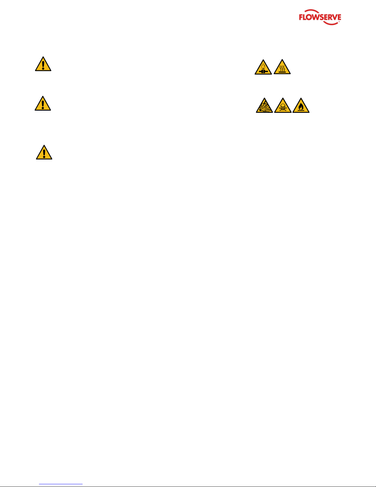
Symbol
Meaning
Description
Pressure
Hazard
Danger!
All provisions and legislation in relation to pressurized equipment
must be observed.
Suspended
Load!
Danger!
Falling loads can cause serious injury or death. Never step under
suspended loads!
Center of
Gravity!
Warning!
Adequate lifting gear must be used. Lifting equipment is always
attached to the valve body and actuator.
Hot / Deep Cold
Surface!
Danger!
Extreme surface temperature: adequate personal protection must
be applied. Area hazards must be observed.
Flammable
Substances!
Danger!
Flammable substances are extremely dangerous to work with and
around. The plant operator must avoid any ignition hazard.
Explosive
Substances /
Atmosphere!
Danger!
In a potentially explosive atmosphere, the ignition risk must be
eliminated by adequate equipment and procedures.
Toxic
Substances!
Warning!
Warning sign for toxic substances. The plant operator is responsible
for protective measures and safety procedures.
Page 8

ARGUS
8
Installation & Operating Instructions
FK 75C and FK 76C
Safety Information
2.6 Ball Valve as Pressure Equipment
A valve is pressure bearing equipment usually integrated into a piping system. Any hazard for persons or for the
environment which might arise from the pressurized substances (“fluids”) being transported within the pipeline system
must be eliminated.
In Europe, Directive 2014/68/EU, i.e. the ”European Pressure Equipment Directive” (PED), and the corresponding laws
and standards govern design, material selection, manufacture and conformity assessment of pressure equipment for
the European market. ASME B16.34 e.g. and the associated standards as well as the pertinent publications of the
American Petroleum Institute provide widely accepted rules and guidelines for qualified valve design and production.
Material selection, design, calculation, and quality assurance during material procurement, in production and on
finished products are the main guarantors to eliminate pressure-related hazards when the ball valves are used as
intended.
The ball valve must be designed and qualified in compliance with all statutory legal regulations at the location
of installation.
DANGER of Pressure Hazards
The manufacturer nameplate permanently attached to the ball valve body
indicates the operating limits of the equipment. The maximum permissible
pressure and the maximum permissible temperature must never be
exceeded. The substances transported and treated must comply with the
specification applied for the valve design. Legislation, directives, and
regulations must be followed.
2.7 Use in Potentially Explosive Atmosphere
ARGUS ball valves are generally suitable for operation in potentially explosive atmospheres. When used as intended,
the ball valves do not have their own potential sources of ignition and are therefore not "equipment" as defined by
Article 1 of Directive 2014/34/EU (European "ATEX Directive”) e.g..
DANGER in Hazardous “Ex Area”
In the case of potentially explosive atmospheres, the specific limit values
applicable to the hazardous area must be observed. This relates in
particular to the permissible fluid temperature or valve surface
temperature.
The personnel entrusted with installation and operation in potentially explosive
atmospheres must be adequately qualified and must wear a personal protection
equipment suitable for explosive atmospheres. All applicable laws, directives
and regulations for hazardous areas must be followed.
2.8 Automated Ball Valve – Safety Aspects
When the ball valve is equipped with a pneumatic, electric, or hydraulic actuation systems, particular risks arise from
the automated functioning, the operation of the instruments, or at the function test.
The valve must never be operated when uninstalled from the pipeline.
WARNING: Risk of Injury when operating outside pipeline
Automated ball valves may only be operated when installed in a pipeline.
Outside the pipeline, the actuation system shall be stored in an
unpressurized and de-energized state.
In case a function test of the uninstalled unit is necessary, the interior of
the valve must be capped in a way that no limbs can enter. Safe distance
must be kept from moving parts.
The personnel entrusted with installation, connection, and operation of the units must be particularly qualified for the
specific automation and instrumentation.
Electric hazards must be avoided. Uncontrolled pneumatic or hydraulic energy may cause severe injuries.
Instrumentation and actuation components must be suitable for the operating environment.
It is essential that the safety instructions concerning each component are followed. As a rule, the manufacturer
nameplate on instrumentation and actuator as well as the user instructions must be strictly observed.
Page 9
ARGUS
9
Installation & Operating Instructions
Ball Valve FK 75C and FK 76C
Delivery / Goods Receipt
3 Delivery / Goods Receipt
3.1 Transportation
Ball valves and/or ball valve assemblies and accessories must be delivered in safe packaging. It is also necessary to
comply with the applicable regulations on load securing. The equipment must in particular be protected against tilting
and slipping.
ARGUS ball valves are delivered with factory fitted protective caps which prevent the penetration of dirt and foreign
particles into the interior. Furthermore, the caps protect the flange sealing surface.
Packaging methods (e.g. “Seaworthy Packing”) are chosen in accordance with customer specification or in order to
protect the equipment during special transport modes.
Immediately after receipt of the product/system it must be checked against the delivery/shipping documents for its
completeness and that there has been no damage in transportation.
Any shortage and/or damage must be reported immediately to Flowserve. Later claims cannot be accepted.
3.2 Goods Acceptance / Verification of the Delivery and Accompanying Documents
A delivery note is enclosed with each delivery. The correctness and completeness of the delivery must be inspected
and confirmed to the deliverer.
The appropriate installation and operating instructions as well as required compliance documentation are part of the
delivery. Their absence must be advised to the supplier.
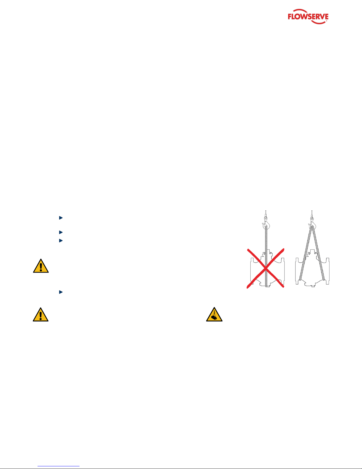
3.3 Unpacking / Transport to Storage Area
In the case of larger valves or complete units, it may be necessary to use a hoist with lifting straps for withdrawing the
delivered goods from the packing:
Loosen and remove load securing material and wedges within the
package.
Dismantle the crate, where necessary.
Position the lifting straps around the ball valve body.
WARNING: Observe Center of Gravity
When using lifting belts on ball valve actuator units, the center of gravity
of the unit can be higher than the attachment point. The total unit must be
secured against twisting and tilting.
Protect accessories (actuator, instrumentation, piping) and
attachments from damage.
DANGER under suspended loads
Never stand under suspended loads!
3.4 Identification of the Delivery
The details on the ball valve nameplate must correspond with the details on the delivery document
(delivery note).
3.5 Storage
Ball valves must be stored in a suitable place, dry and free from dirt or detrimental atmosphere. It is advisable not to
remove the protective caps in order to protect the valve interior and the connection sealing surfaces or threads.
As a rule, the ball valve is to be stored in the open position as supplied.
3.6 Transport to the Assembly and Utilization Site
The instructions under 3.3 are to be observed.
Page 10

ARGUS
10
Installation & Operating Instructions
FK 75C and FK 76C
Nameplate: Identification of the Ball Valve
4 Nameplate: Identification of the Ball Valve
The manufacturer nameplate permanently affixed to the ball valve body provides the most important information
regarding the design and use of the ball valve.
If the type plate is missing or illegible, the ball valve must not be put into operation.
1 Nominal Pressure (CLASS)
2 ARGUS Type
3 Ball Material
4 Seat Material
5 BOM (Bill of Materials) No. / Reference
6 Design Standard
7 Date of Manufacture
8 Stem Material
9 Body Material
10 MOP (Maximum Operating Pressure) [bar] at Minimum Temperature [°C]
11 MOP (Maximum Operating Pressure) [bar] at Maximum Temperature [°C]
12 Serial Number
13 Nominal Pipe Size (NPS) [inch]
Additional Marking on the Ball Valve
In addition to the essential information given on the nameplate, the ball valve may come with supplementary stamping,
plates, decals, or labels in compliance with statutory regulations, client specification, special application rules or to
advise particular application limits.
Pay attention to all marking on the valve.
Page 11

ARGUS
11
Installation & Operating Instructions
Ball Valve FK 75C and FK 76C
Installation
5 Installation
Ball valve series FK 75C and FK 76C are usually intended to be connected to pipework with matching flange
connection.
The ball valve is designed for use under normal load in the pipework. Particular operating conditions must be clearly specified
in the customer requisition/inquiry. In the case of deviations from these conditions, Flowserve must be consulted.
5.1 Preparation for Installation
The following points must be observed before installation:
Pipework must be strong enough to safely bear the ball valve and its accessories. Verify if special support
is needed for the unit.
Pipework must be cleaned before installation.
There must be sufficient clearance above and to the side of the valve and/or attachments to permit
maintenance, inspection or repair work without any risk.
Extensions and attachments that are used for heat removal or heating must not be insulated.
If the ball valve is intended for regular manual operation, then a standing area must be provided for the
operator on which the latter can safely apply the necessary forces in accordance with applicable user,
local and national standards as well as guidelines.
Observe possible flow direction! For unidirectional ball valves (special
case), the flow direction is indicated by an arrow on the body.
5.2 Installing Flange Connection
Transport the ball valve to the assembly location using suitable lifting devices which are appropriate to the
weight and the size of the ball valve (052-01).
052-01
Remove protective caps (052-02).
052-02
Clean the pipework end, connection flange and sealing surfaces (052-03).
Page 12

ARGUS
12
Installation & Operating Instructions
FK 75C and FK 76C
Installation
052-03
Assembling the first flange:
– Fix the ball valve to the connection with some bolts and position the seal.
– Ensure the correct position of the ball valve and seal (052-04).
052-04
Tighten the bolts crosswise (052-05).
052-05
Assembling the second flange: Procedure as for the first flange (052-06).
052-06
Check tightness after completed assembly works.
Page 13

ARGUS
13
Installation & Operating Instructions
Ball Valve FK 75C and FK 76C
Installation
Safety instructions relating to the pipework system (including fittings) are
to be provided by the operator.
Design-relevant pressure and temperature fluctuations must be inquired
with the manufacturer.
The flanges used are standard flanges (e. g. standard flanges per
ASME B16.5). The tightening torques of the bolts must be determined
according to the standard flange connection.
After completion of the assembly – before the ball valve is actuated – a
flushing of the pipeline system is recommended.
If pipework forces are transferred to the valve, then the design must be
inquired with the manufacturer accordingly.
If the ball valve is intended to serve as permanent shut-off from the
atmosphere, a blank flange or equivalent end must be provided by the
end user.
5.3 Actuator Mounting / Orientation of the Valve-Actuator Unit
Actuators are usually installed above the ball valve. The shaft connection is in a vertical position. Other installation
orientations are possible according to the evaluation of the specific conditions.
If in doubt, please consult Flowserve.
In case of heavy and/or asymmetrical actuators or with units which are
not installed vertically, bending and/or torsional forces can occur –
especially on extended stems with a stuffing box.
Support of the actuator in the installed position may be required.
Additionally, in the case of critical vibrations or impacts during operation,
it can be useful to additionally support the actuator or provide shock
absorption.
Page 14

ARGUS
14
Installation & Operating Instructions
FK 75C and FK 76C
Commissioning – Recommended Practice
6 Commissioning – Recommended Practice
Before commissioning and putting into service, the valve tightness must be verified.
6.1 Flushing and Pressure Testing the Pipework
Flushing, "hydro testing" and drying are necessary steps before commissioning or placing the unit in service:
Thorough flushing cleans pipework, valves and fittings from dirt and foreign particles.
To avoid damage to the seat elements during rinsing, the ball valve must
be in the open position.
After cleaning, the flange connections must be checked again.
If necessary, tighten the bolts again.
The ball valve must be operated after flushing.
To prevent damage, the valve must be operated to fully open or to fully closed
position (90°) without intermediate position.
The pressure test of the pipework system confirms the tightness and strength of the system section.
DANGER at Pressure Testing
The operating and test limits of the ball valve according to the
design standard may never be exceeded!
6.2 Positions of the Ball Valve
The ball valve is open when the flat flanks of the 2 flat stem head or the groove on the square stem head are in parallel
to the flow direction.
Groove on the
square stem
head
2 flat stem
head
Page 15

ARGUS
15
Installation & Operating Instructions
Ball Valve FK 75C and FK 76C
Commissioning – Recommended Practice
When using a valve wrench, the position of the ball valve must be
recognizable by the position of the wrench – for safety reasons:
– Open position: Valve wrench parallel to body/pipework
– Closed position: Valve wrench crosswise/perpendicular (90°) to
the pipework
ARGUS FK ball valves must not be used as throttle or control valves.
Page 16
ARGUS
16
Installation & Operating Instructions
FK 75C and FK 76C
Maintenance
7 Maintenance
7.1 Periodic Inspection
Regular maintenance and servicing highly depend on the actual operating conditions and the operating frequency of
the valve.
It is recommended to periodically inspect the pipework section for leaks and damage. The flange connections must
also be inspected.
Flowserve Service Teams and "Quick Response Centers" offer
worldwide expert service for inspection, repair, and qualification of
ARGUS ball valves on site or under factory conditions.
The recommended inspection can be executed with the valve installed in line. As a rule, the normal plant operation
does not have to be interrupted:
Inspect the outer seals for leaks and re-tighten if necessary.
Inspect the valve for external damage.
Clean the valve and repaint if necessary.
If possible, open and close the valve and ensure that the valve stem runs smoothly.
A jerky running of the shaft can indicate increased torque.
Inspect all accessories for tight fit and function.
DANGER at automated operation
Keep hands, hair or clothing away from all moving parts! The
operating instructions and safety instructions for the automation
components must be followed.
Failure to do so could result in serious injury.
7.2 Exchanging Parts
Under particularly stressful operating conditions, wear of sealing components of the ball valve may occur after a certain
period of time. Also very critical or severe service may require that parts of the ball valve are periodically renewed.
Only original spare parts may be used.
Spare Part Information
Flowserve provides spare parts for all ARGUS ball valve types. For inquiry or order, it is important that the ball valve in
use is clearly specified.
Technical identification is made either with reference to the item in the order documents of the valve i.e. the order
acknowledgment, delivery note or invoice, or the data taken from the nameplate: order number, article number or serial
number.
Specification particulars for spare parts inquiry/order and for technical
documentation:
Purchase order documents or nameplate
Technical documentation for the exchange
Technical documentation required for disassembly, part exchange and assembly of the valve is available from
Flowserve after clear technical identification of the ball valve and is, in principle, attached to spare part deliveries.
ONLY QUALIFIED PERSONNEL and SUITABLE EQUIPMENT
Only appropriately qualified personnel may be entrusted with
maintenance and repair work. The tools and equipment used must be
suitable and the processes must be safe.
Observe all health and safety regulations.
In case of doubt about the qualification of the personnel or about the
appropriate equipment, Flowserve must be consulted.
As an attachment to this manual, you will find Disassembly and Assembly Instructions for ARGUS FK 75C
and FK 76C.
Page 17
ARGUS
17
Installation & Operating Instructions
Ball Valve FK 75C and FK 76C
Maintenance
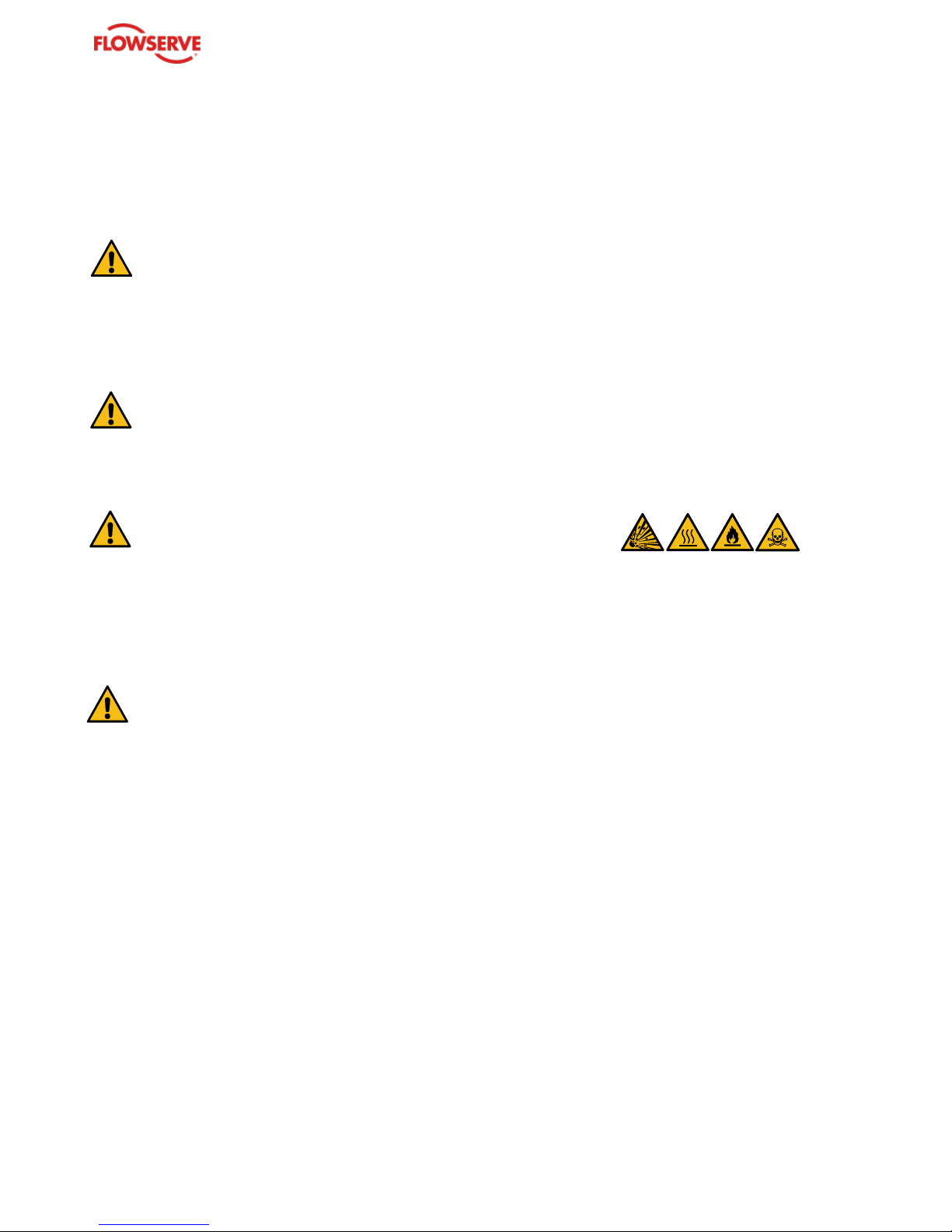
DANGER
Ball valve must be depressurized!
Operate the ball valve to allow trapped pressure to escape.
Beware extreme surface temperature!
DANGER TO LIFE
Pay attention to hazardous substances!
Risk of explosion, fire, poisoning or caustic burns!
WARNING
Repair welding or connection welding on pressure equipment is not
permitted.
7.3 Returning the Ball Valve: “Valve Information Sheet”
According to the Flowserve Returned Goods Safety Procedure ball valves, which are returned to Flowserve, must be
free of dangerous fluid residues. The sender will receive from Flowserve a form, which must be filled-in and signed by
the responsible organization and which must clearly attest the fact that the valve does not pose any risk to persons or
to the environment when it is delivered and/or during and after disassembly.
Flowserve can only accept a return, if the completed and bindingly signed Flowserve form accompanies the
delivery.
Page 18
ARGUS
18
Installation & Operating Instructions
FK 75C and FK 76C
Decommissioning, De-Installation and
Disposal
8 Decommissioning, De-Installation and Disposal
8.1 Decommissioning and De-Installation
After decommissioning, it is advisable to disconnect the actuation unit and the control components from the valve
before dismounting it from the pipework.
DANGER
Ball valve must be depressurized!
Operate the ball valve so that trapped pressure can escape.
Beware extreme temperature!
If hoisting gear is necessary, lifting straps should be used:
Position the lifting straps around the ball valve body.
DANGER when lifting large automated ball valves
For large automated ball valves, the center of gravity must be observed.
Never lift the complete automated ball valves with lifting gear only
attached to the actuator!
DANGER TO LIFE
Pay attention to hazardous substances (fluids and gases)!
Risk of explosion, fire, poisoning or caustic burns!
8.2 Disposal
When disposing of the ball valve, the applicable local regulations and laws must be observed.
DANGER
Pay attention to hazardous fluid residues!
Risk of poisoning or caustic burns!
Protect vulnerable environment.
It may be possible to insert the clean decontaminated ball valve components and parts into a recycling program.
Page 19
ARGUS
19
Installation & Operating Instructions
Ball Valve FK 75C and FK 76C
FK 75C Disassembly / Assembly
DANGER
Ball valve must be depressurized!
Operate the ball valve so that trapped
pressure can escape.
Only adequately qualified and instructed personnel
with adequate personal protective equipment and
tools may execute this task.
Always pay attention to dangerous fluids and
extreme surface temperature.
Use appropriate tools and hoisting gear.
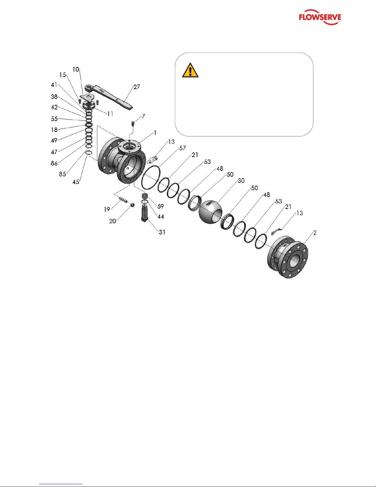
FK 75C Disassembly / Assembly
Total Disassembly
Bring stem (31) into the CLOSED position.
Remove snap ring (22) and stop disc (10).
Unscrew cylindrical hexagon Allen head screws (15).
Dismantle bonnet (11) with wiper ring (41), bearing tape (38), and sealing ring (42), thrust ring (18) with bearing
tape (55) and sealing ring (49).
Unscrew hexagon nuts (20) from body (2).
Remove body (2), O-ring (51) and sealing ring (57) from body (1).
Remove ball (30), ball support pads (13), ball seats (50) with sealing ring (48), thrust ring (53), and
belleville washer (21).
Press stem (31) downward and remove from body (1) with bushing (59) and thrust ring (44).
Remove ring (47), sleeves (85, 86) and disk (45) upwards.
Replacing Stem Sealing
Proceed as for Total Disassembly until.
Replace seal (47) and sleeves (85, 86).
Disk (45) can remain in body (1).
If O-ring sealing is required instead of seal (47), remove sleeves (85, 86).
Disk (45) and thrust ring (18) are then replaced by O-ring sealing (drawings & article number on request).
Additionally, belleville washer (17) and ring (43) are needed.
Inspect all parts for wear and tear or for any sign of improper functioning.
Partial disassembly may be sufficient.
For reassembly, proceed in reverse order of disassembly.
Replace the worn items by original Flowserve spare parts.
Page 20
ARGUS
20
Installation & Operating Instructions
FK 75C and FK 76C
FK 76C Disassembly / Assembly
DANGER
Ball valve must be depressurized!
Operate the ball valve so that trapped
pressure can escape.
Only adequately qualified and instructed personnel
with adequate personal protective equipment and
tools may execute this task.
Always pay attention to dangerous fluids and
extreme surface temperature.
Use appropriate tools and hoisting gear.
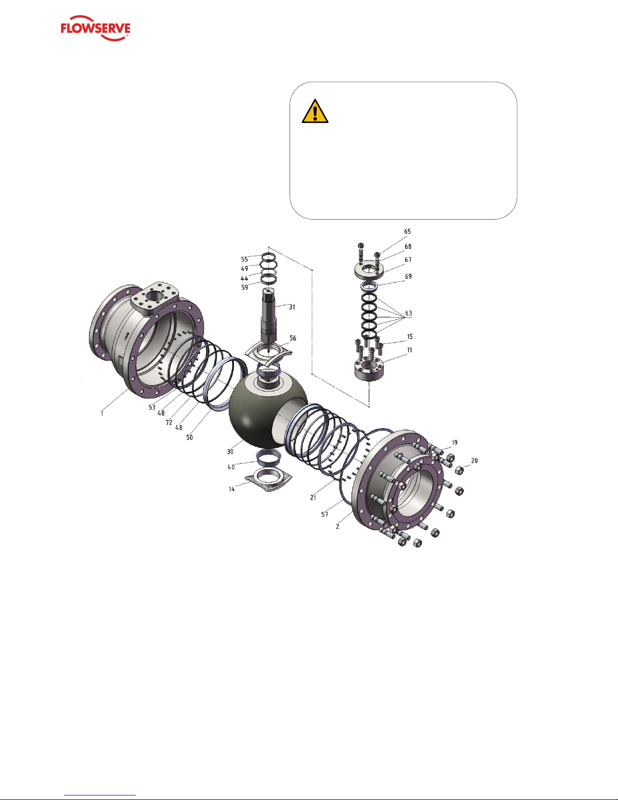
FK 76C Disassembly / Assembly
Total Disassembly – Standard
Bring stem (31) into the CLOSED position.
Unscrew hexagon nuts (65).
Remove packing gland (67) with thrust ring (69).
Unscrew Allen head screws (15).
Remove stuffing box (11) with sealing rings (63), bearing tape (55), and sealing ring (49).
Pull out stem (31) with bearing tape (59), thrust ring (44) and compression spring (56).
Unscrew hexagon nuts (20) from the body (2).
Remove body (2) and seal ring (57) from the body (1).
Remove ball (30), counter-bearing (14) with bearing bushing (40), ball seats (50) with sealing rings (48),
thrust rings (72) as well as thrust rings (53) and compression springs (21).
Replacing Stem Sealing (Packing)
Proceed as for Total Disassembly until.
Remove and replace sealing rings (63).
Inspect all parts for wear and tear or for any sign of improper functioning.
Partial disassembly may be sufficient.
For reassembly, proceed in reverse order of disassembly.
Replace the worn items by original Flowserve spare parts.
Page 21

ARGUS
21
Installation & Operating Instructions
Ball Valve FK 75C and FK 76C
FK 76C Disassembly / Assembly
----------------------------------------------------------------------------------------------------------------------------------------------------------------------------------------------------Document No. BA1010_EN Rev.: A – 2019-01-07
Disclaimer
Information in this user manual is believed to be complete and reliable. In spite of all Flowserve’s efforts to provide comprehensive information and instructions, sound
engineering and safety practices must always be used. Qualified personnel must be consulted. For any further query, Flowserve should be contacted.
Page 22

ARGUS
22
Installation & Operating Instructions
FK 75C and FK 76C
These instructions and detailed product bulletins are also available for download under:
http://flowserve.com
Your FLOWSERVE Contact:
Flowserve factory contacts:
Flowserve Corporation
1978 Foreman Drive
Cookeville, TN 38501
Tel: +1 931 432 4021
Flowserve Corporation
3993 W. Sam Houston Parkway North
Suite 100
Houston, TX 77043
Tel: +1 281 469 4166
Flowserve ARGUS
Lead Product Operation contact:
Flowserve Flow Control GmbH
Rudolf-Plank-Str.2
76275 Ettlingen
Germany
Tel: +49 7243 103 0
 Loading...