

Page 1

DMX/DMXD/DMXH/DMXDH centrifugal
pumps
USER INSTRUCTIONS
Installation
Operation
Multistage, single/double suction, horizontally split volute
type centrifugal pumps
PCN = 85392728 – 10/09 (E)
O
riginal instructions
Maintenance
SLEEVE/KTB CONFIGURATION
These instructions must be read prior to installing,
operating, using and maintaining the equipment.
Page 2

DMX/DMXD/DMXH/DMXDH USER INSTRUCTIONS ENGLISH 85392728 - 10/09
CONTENTS
1 INTRODUCTION AND SAFETY ...................... 3
1.1 General ....................................................... 3
1.2 CE marking and approvals ......................... 3
1.3 Disclaimer ................................................... 3
1.4 Copyright .................................................... 3
1.5 Duty conditions ........................................... 3
1.6 Safety.......................................................... 4
1.7 Warning labels ............................................ 7
1.8 Specific machine performance ................... 8
1.9 Noise level .................................................. 8
2 TRANSPORT AND STORAGE ...................... 10
2.1 Consignment receipt and unpacking ........ 10
2.2 Handling ................................................... 10
2.3 Lifting ........................................................ 10
2.4 Extended storage ..................................... 11
2.5 Recycling and end of product life ............. 14
3 PUMP DESCRIPTION .................................... 15
3.1 Configurations .......................................... 15
3.2 Name nomenclature ................................. 15
3.3 Design of major parts ............................... 15
3.4 Performance and operating limits ............. 16
4 INSTALLATION .............................................. 17
4.1 Location .................................................... 17
4.2 Foundation ................................................ 17
4.3 Grouting .................................................... 18
PAGE PAGE
5.5 Guarding................................................... 31
5.6 Priming and auxiliary supplies.................. 31
5.7 Starting the pump ..................................... 31
5.8 Running or operation ................................ 31
5.9 Stopping and shutdown ............................ 32
5.10 Hydraulic, mechanical and electrical duty 32
6 MAINTENANCE ............................................. 34
6.1 Maintenance schedule ............................. 34
6.2 Spare parts ............................................... 35
6.3 Recommended spares and consumable
items ......................................................... 35
6.4 Tools required ........................................... 35
6.5 Fastener torques ...................................... 35
6.6 Disassembly ............................................. 36
6.7 Examination of parts................................. 39
6.8 Assembly of pump and seal ..................... 40
7 FAULTS; CAUSES AND REMEDIES ........... 47
8 PARTS LIST AND DRAWINGS ..................... 49
9 CERTIFICATION ............................................ 55
10 OTHER RELEVANT DOCUMENTATION AND
MANUALS ...................................................... 55
10.1 Supplementary user instruction manuals . 55
10.2 Change notes ........................................... 55
10.3 Additional sources of information ............. 55
10.4 Customer Data Sheet ............................... 56
4.4 Initial alignment ......................................... 20
4.5 Piping ........................................................ 24
4.6 Electrical connections ............................... 26
4.7 Final shaft alignment check ...................... 27
4.8 Protection systems ................................... 27
5 COMMISSIONING, START-UP, OPERATION
AND SHUTDOWN .......................................... 28
5.1 Precommissioning procedure ................... 28
5.2 Pump lubricants ........................................ 29
5.3 Impeller wearring clearance ..................... 31
5.4 Direction of rotation .................................. 31
Page 2 of 60
Page 3

DMX/DMXD/DMXH/DMXDH USER INSTRUCTIONS ENGLISH 85392728 - 10/09
1 INTRODUCTION AND SAFETY
1.1 General
These Instructions must always be kept
close to product's operating location or directly
with the product.
Flowserve's products are designed, developed and
manufactured with state-of-the-art technologies in
modern facilities. The unit is produced with great care
and commitment to continuous quality control, utilising
sophisticated quality techniques, and safety
requirements.
Flowserve is committed to continuous quality
improvement and being at service for any further
information about the product in its installation and
operation or about its support products, repair and
diagnostic services.
These instructions are intended to facilitate
familiarization with the product and its permitted use.
Operating the product in compliance with these
instructions is important to help ensure reliability in
service and avoid risks. The instructions may not take
into account local regulations; ensure such regulations
are observed by all, including those installing the
product. Always coordinate repair activity with
operations personnel, and follow all plant safety
requirements and applicable safety and health
laws/regulations.
These instructions must be read prior to
installing, operating, using and maintaining the
equipment in any region worldwide. The
equipment must not be put into service until all
the conditions relating to safety, noted in the
instructions, have been met. Failure to follow
and apply the present user instructions is
considered to be misuse. Personal injury,
product damage, delay or failure caused by
misuse are not covered by the Flowserve
warranty.
1.2 CE marking and approvals
It is a legal requirement that machinery and
equipment put into service within certain regions of
the world shall conform with the applicable CE
Marking Directives covering Machinery and, where
applicable, Low Voltage Equipment, Electromagnetic
Compatibility (EMC), Pressure Equipment Directive
(PED) and Equipment for Potentially Explosive
Atmospheres (ATEX).
Where applicable, the Directives and any additional
Approvals, cover important safety aspects relating to
machinery and equipment and the satisfactory
provision of technical documents and safety
instructions. Where applicable this document
incorporates information relevant to these Directives
and Approvals. To confirm the Approvals applying
and if the product is CE marked, check the serial
number plate markings and the Certification, see
section 9, Certification.
1.3 Disclaimer
Information in these User Instructions is believed
to be reliable. In spite of all the efforts of
Flowserve to provide sound and all necessary
information the content of this manual may
appear insufficient and is not guaranteed by
Flowserve as to its completeness or accuracy.
Flowserve manufactures products to exacting
International Quality Management System Standards
as certified and audited by external Quality
Assurance organisations. Genuine parts and
accessories have been designed, tested and
incorporated into the products to help ensure
continued product quality and performance in use. As
Flowserve cannot test parts and accessories sourced
from other vendors the incorrect incorporation of such
parts and accessories may adversely affect the
performance and safety features of the products. The
failure to properly select, install or use authorised
Flowserve parts and accessories is considered to be
misuse. Damage or failure caused by misuse is not
covered by Flowserve's warranty. In addition, any
modification of Flowserve products or removal of
original components may impair the safety of these
products in their use.
1.4 Copyright
All rights reserved. No part of these instructions may
be reproduced, stored in a retrieval system or
transmitted in any form or by any means without prior
permission of Flowserve Corporation.
1.5 Duty conditions
This product has been selected to meet the
specifications of your purchaser order. The
acknowledgement of these conditions has been sent
separately to the Purchaser. A copy should be kept
with these instructions.
The product must not be operated beyond
the parameters specified for the application. If
there is any doubt as to the suitability of the
Page 3 of 60
Page 4
DMX/DMXD/DMXH/DMXDH USER INSTRUCTIONS ENGLISH 85392728 - 10/09
product for the application intended, contact
Flowserve for advice, quoting the serial number.
If the conditions of service on your purchase order are
going to be changed (for example liquid pumped,
temperature or duty) it is requested that the user seeks
Flowserve’s written agreement before start up.
1.6 Safety
1.6.1 Summary of safety markings
These user instructions contain specific safety
markings where non-observance of an instruction
would cause hazards. The specific safety markings
are:
This symbol indicates electrical safety
instructions where non-compliance will involve a high
risk to personal safety or the loss of life.
This symbol indicates safety instructions where
non-compliance would affect personal safety and
could result in loss of life.
This symbol indicates “hazardous substances
and toxic fluid” safety instructions where noncompliance would affect personal safety and could
result in loss of life.
This symbol indicates safety
instructions where non-compliance will involve some
risk to safe operation and personal safety and would
damage the equipment or property.
This symbol indicates explosive atmosphere
marking according to ATEX. It is used in safety
instructions where non-compliance in the hazardous
area would cause the risk of an explosion.
This symbol indicates is used in safety
instructions to remind not to rub non-metallic surfaces
with a dry cloth; ensure cloth is damp. It is used where
non-compliance in the hazardous area would cause
the risk of an explosion.
This sign is not a safety symbol but
indicates an important instruction in the assembly
process.
1.6.2 Personnel qualification and training
All personnel involved in the operation, installation,
inspection and maintenance of the unit must be
qualified to carry out the work involved. If the
personnel in question do not already possess the
necessary knowledge and skill, appropriate training
and instruction must be provided. If required the
operator may commission the manufacturer / supplier
to provide applicable training.
Always co-ordinate repair activity with operations and
health and safety personnel, and follow all plant safety
requirements and applicable safety and health laws
and regulations.
1.6.3 Safety action
This is a summary of conditions and actions to
prevent injury to personnel and damage to the
environment and to equipment. (For products
used in potentially explosive atmospheres
section 1.6.4 also applies.)
Do not use pump as a support for piping. Do not
mount expansion joints, unless authorized by
Flowserve in writing, so that their force, due to
internal pressure, acts on the pump flange.
(See section 5, Commissioning, startup, operation
and shutdown.)
opened (Unless otherwise instructed at a specific
point in the user instructions). This is recommended
to minimize the risk of overloading at full flow and
damaging the pump at zero flow. Pumps may be
started with the valve further open only on
installations where this situation cannot occur. The
pump outlet control valve may need to be adjusted to
comply with the duty following the run-up process.
(See section 5, Commissioning start-up, operation
and shutdown.)
pump is running. Running the pump at zero flow or
below the recommended minimum flow continuously
will cause damage to the pump and seals. Low flow
rates may cause a reduction in pump/bearing life,
Prevent excessive external pipe load
Ensure correct lubrication
Start the pump with outlet valve partly
Never run the pump dry.
Inlet valves to be fully open when
Page 4 of 60
Page 5
DMX/DMXD/DMXH/DMXDH USER INSTRUCTIONS ENGLISH 85392728 - 10/09
overheating of the pump, instability and cavitation/
vibration.
Do not run the pump at abnormally
high or low flow rates. Operating at a flow rate higher
than normal or at a flow rate with no backpressure on
the pump may overload the motor and cause pump
cavitation.
Never do maintenance work when
the unit is connected to power.
When the pump is handling hazardous
liquids care must be taken to avoid exposure to
the liquid by appropriate sitting of the pump,
limiting personnel access and by operator
training. If the liquid is flammable and/or
explosive, strict safety procedures must be
applied.
HANDLING COMPONENTS
Many precision parts have sharp corners and the
wearing of appropriate safety gloves and
equipment is required when handling these
components. To lift heavy pieces above 25 kg (55
lb) use an appropriate crane for the mass and in
accordance with current local regulations.
Coupling guards must not be removed while
the pump is operational.
THERMAL SHOCK
Rapid changes in the temperature of the liquid
within the pump will cause thermal shock, which
can result in damage or breakage of components
and should be avoided.
HOT (and cold) PARTS
If hot or freezing components or auxiliary heating
supplies can present a danger to operators and
persons entering the immediate area action must
be taken to avoid accidental contact. If complete
protection is not possible, the machine access
must be limited to maintenance staff only, with
clear visual warnings and indicators to those
entering the immediate area. Note: bearing
housings must not be insulated and drive motors
and bearings may be hot.
If the temperature is greater than 68 °C (154°F) or
below -5 °C (20 °F) in a restricted zone, or
exceeds local regulations, action as above shall
be taken.
1.6.4 Products used in potentially explosive
atmospheres
Measures are required to:
• Avoid excessive temperature
• Prevent the build up of explosive mixtures
• Prevent the generation of sparks
• Prevent leakages
• Maintain the pump to avoid hazard
The following instructions for pumps and pump units
when installed in potentially explosive atmospheres
must be followed to help ensure explosion protection.
Both electrical and non-electrical equipment must
meet the requirements of European Directive
94/9/EC.
1.6.4.1 Scope of compliance
Use equipment only in the zone for which it is
appropriate. Always check that the driver, drive
coupling assembly, seal and pump equipment are
suitably rated and/or certified for the classification of
the specific atmosphere in which they are to be
installed.
Where Flowserve has supplied only the bare shaft
pump, the Ex rating applies only to the pump. The
party responsible for assembling the ATEX pump set
shall select the coupling, driver and any additional
equipment, with the necessary CE Certificate/
Declaration of Conformity establishing it is suitable for
the area in which it is to be installed.
The output from a variable frequency drive (VFD) can
cause additional heating effects in the motor and so,
for pumps sets with a VFD, the ATEX Certification for
the motor must state that it is covers the situation
where electrical supply is from the VFD. This
particular requirement still applies even if the VFD is
in a safe area.
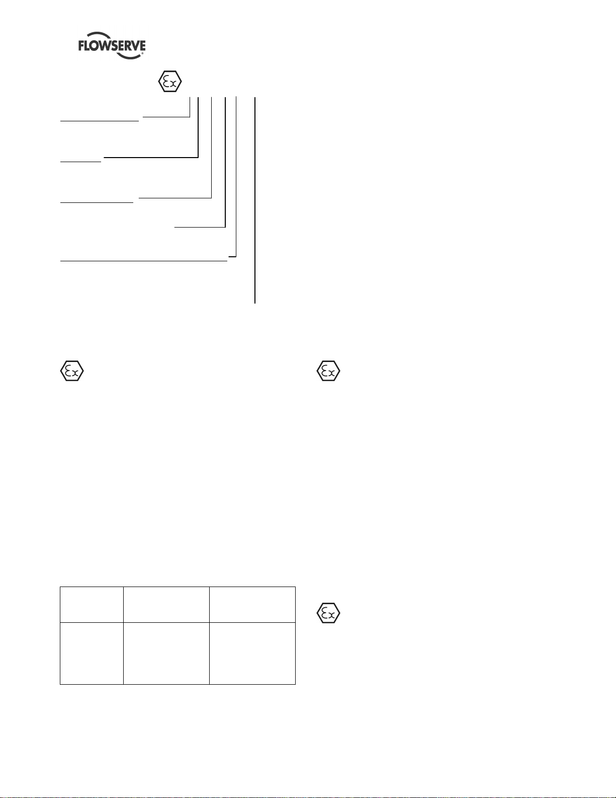
1.6.4.2 Marking
An example of ATEX equipment marking is shown
below. The actual classification of the pump will be
engraved on the nameplate.
Page 5 of 60
Page 6
DMX/DMXD/DMXH/DMXDH USER INSTRUCTIONS ENGLISH 85392728 - 10/09
II 2 GD c IIB 135 ºC (T4)
Equipment Group
I = Mining
II = Non-mining
Category
2 or M2 = High level protection
3 = normal level of protection
Gas and/or Dust
G = Gas; D= Dust
c = Constructional safety
(in accordance with prEN13463-5)
Gas Group (Equipment Group II only)
IIA - Propane (Typical)
IIB - Ethylene (Typical)
IIC - Hydrogen (Typical)
Maximum surface temperature (Temperature Class)
(See section 1.6.4.3.)
1.6.4.3 Avoiding excessive surface
temperatures
The responsibility for compliance with the
specified maximum liquid temperature is with the
plant operator.
If an explosive atmosphere exists during the
installation, do not attempt to check the direction of
rotation by starting the pump unfilled. Even a short
run time may give a high temperature resulting from
contact between rotating and stationary components.
Where there is any risk of the pump being run against
a closed valve generating high liquid and casing
external surface temperatures, the users shall fit an
external surface temperature protection device.
Avoid mechanical, hydraulic or electrical overload by
using motor overload trips, temperature monitor or a
power monitor and make routine vibration monitoring
checks.
In dirty or dusty environments, regular checks shall
be made and dirt removed from areas around close
clearances, bearing housings and motors.
1.6.4.4 Preventing the build up of explosive
mixtures
ENSURE THE EQUIPMENT TEMPERATURE
CLASS IS SUITABLE FOR THE HAZARD ZONE
Pumps have a temperature class as stated in the
ATEX Ex rating on the nameplate. These are based
on a maximum ambient temperature of 40 °C
(104 °F); refer to Flowserve for higher ambient
temperatures.
The temperature of the liquid handled influences the
surface temperature on the pump. The maximum
permissible liquid temperature depends on the ATEX
temperature class and must not exceed the values in
the table that follows.
The temperature rise at the seals and bearings and
due to the minimum permitted flow rate is taken into
account in the temperatures stated.
Temperature
class to
prEN 13463-1
T6
T5
T4
T3
T2
T1
*The table only takes the ATEX temperature class into
consideration. Pump design or material as well as component
design or material may further limit the maximum working
temperature of the liquid.
Maximum surface
temperature
permitted
85 °C (185 °F)
100 °C (212 °F)
135 °C (275 °F)
200 °C (392 °F)
300 °C (572 °F)
450 °C (842 °F)
Temperature limit of
Consult Flowserve
Consult Flowserve
115 °C (239 °F) *
180 °C (356 °F) *
275 °C (527 °F) *
400 °C (752 °F) *
liquid
ENSURE THE PUMP IS PROPERLY FILLED
AND VENTED AND DOES NOT RUN DRY
Ensure the pump and relevant suction and discharge
pipeline system is totally filled with liquid at all times
during the pump operation, so that an explosive
atmosphere is prevented. In addition it is essential to
make sure that seal chambers, auxiliary shaft seal
systems and any heating and cooling systems are
properly filled. If the operation of the system cannot
avoid this condition, users shall fit an appropriate dry
run protection device (e.g. liquid detection or a power
monitor).
To avoid potential hazards from fugitive emissions of
vapor or gas to atmosphere the surrounding area
shall be well ventilated.
1.6.4.5 Preventing sparks
To prevent a potential hazard from mechanical
contact, the coupling guard must be non-sparking
and anti-static for Category 2.
To avoid the potential hazard from random induced
current generating a spark, the baseplate shall be
properly grounded.
Avoid electrostatic charge: do not rub non-metallic
Page 6 of 60
Page 7

DMX/DMXD/DMXH/DMXDH USER INSTRUCTIONS ENGLISH 85392728 - 10/09
surfaces with a dry cloth; ensure cloth is damp.
The coupling must be selected to comply with 94/9/EC
and correct alignment must be maintained.
1.6.4.6 Preventing leakage
The pump shall only be used to handle liquids
for which it has been approved to have the correct
corrosion resistance.
Avoid entrapment of liquid in the pump and
associated piping due to closing of suction and
discharge valves, which could cause dangerous
excessive pressures to occur if there is heat input to
the liquid. This can occur if the pump is stationary or
running.
Bursting of liquid containing parts due to freezing
must be avoided by draining or protecting the pump
and ancillary systems.
Where there is the potential hazard of a loss of a seal
barrier fluid or external flush, the fluid shall be
monitored.
1.7 Warning labels
If leakage of liquid to atmosphere can result in a
hazard, then a liquid detection device shall be
installed.
1.6.4.7 Maintenance to avoid the hazard
CORRECT MAINTENANCE IS REQUIRED TO
AVOID POTENTIAL HAZARDS WHICH GIVE A
RISK OF EXPLOSION
The responsibility for compliance with
maintenance instructions is with the plant owner
or operator.
To avoid potential explosion hazards during
maintenance, the tools, cleaning and painting
materials used must not give rise to sparking or
adversely affect the ambient conditions. Where there
is a risk from such tools or materials, maintenance
must be conducted in a safe area.
A maintenance plan and schedule shall be adopted.
(See section 6, Maintenance).
Page 7 of 60
Page 8

DMX/DMXD/DMXH/DMXDH USER INSTRUCTIONS ENGLISH 85392728 - 10/09
Oil lubricated units only:
1.8 Specific machine performance
For performance parameters see 10.4 Customer
Data Sheet. When the contract requirement specifies
these to be incorporated into User Instructions these
are included here. Where performance data has
been supplied separately to the purchaser these
should be obtained and retained with these User
Instructions if required.
1.9 Noise level
Attention must be given to the exposure of personnel
to the noise, and local legislation will define when
guidance to personnel on noise limitation is required,
and when noise exposure reduction is mandatory.
This is typically 80 to 85 dBA.
The usual approach is to control the exposure time to
the noise or to enclose the machine to reduce
emitted sound. You may have already specified a
limiting noise level when the equipment was ordered,
however if no noise requirements were defined, then
attention is drawn to the following table to give an
indication of equipment noise level so that you can
take the appropriate action in your plant.
Pump noise level is dependent on a number of
operational factors, flow rate, pipework design and
acoustic characteristics of the building, and so the
values given are subject to a 3 dBA tolerance and
cannot be guaranteed.
1.9.1 Pump noise levels
The following tables may be used to determine the
estimated sound pressure levels (SPL), expressed in
dBA (dB), for DMX/DMXD/DMXH/DMXDH pumps.
The values shown have been derived from actual
noise test data and are based on the following
conditions:
a) Equipment is located in a free field above a
reflecting plane in which the reduction in noise
level in all directions is 6 dB in each octave band
for each doubling of distance.
b) Background noise is 10 dB (minimum) below all
noise levels in each octave band.
c) The values shown are at a distance of 1 m
(3.281 ft), horizontally from major pump surfaces
and 1.5 m (4.78 ft) above the floor using the
standard pressure reference of 20 µPa
(0.00002 N/m2).
d) Overall noise level, dBA ("A" scale) is determined
at points of maximum noise level, and the values
of all mid-band frequencies are basis "C" scale
readings.
1.9.2 Overall noise level
Tables below show dBA levels for two stage and
three or more stage pumps, based on the best
efficiency point BEP at design RPM and required
impeller diameter.
For specific gravities less than 1.0, use 1.0 specific
gravity. For specific gravities above 1.0, use the
actual specific gravity.
When the required condition flow falls outside the
range of 75% to 125% of BEP, a Part Load
Correction (PLC) must be added to the noise levels
as follows:
Percent of BEP at required Impeller
Diameter
74 to 62 % or 126 to 136 % +1
61 to 50 % or 137 to 150 % +2
49 to 38 % +3
37 to 25 % +4
PLC DB
Brake Horse Power at Best Efficiency
Point.
2 Stage pump
250 to 350 87
350 to 500 88
500 to 700 89
700 to 940 90
940 to 1100 91
1100 to 1300 92
1300 to 1500 93
Above 1500, contact Flowserve 94
dBA
Page 8 of 60
Page 9

DMX/DMXD/DMXH/DMXDH USER INSTRUCTIONS ENGLISH 85392728 - 10/09
Brake Horse Power at Best Efficiency
Point.
3 to 14 Stages
90 to 110 79
110 to 140 80
140 to 180 81
180 to 220 82
220 to 280 83
280 to 360 84
360 to 450 85
450 to 560 86
560 to 720 87
720 to 900 88
900 to 1125 89
1125 to 1400 90
1400 to 1800 91
1800 to 2250 92
2250 to 2800 93
2800 to 3600 94
3600 to 4500 95
4500 to 5700 96
5700 to 7200 97
7200 to 9000 98
9000 to 11,000 99
11,000 to 14,000 100
dBA
1.9.3 Combined noise levels for pump and
driver components
When two or more sources produce noises that are
sufficiently unrelated (so that interference effects do
not occur) the total combined noise level may be
obtained by a simple addition of dB values according
to the below table.
Difference between two
levels to be Combined, dB
0 3
1 2.5
2 2
4 1.5
6 1
9 0.5
10 0
Add to higher level to
obtain Combined level, dB
Page 9 of 60
Page 10
DMX/DMXD/DMXH/DMXDH USER INSTRUCTIONS ENGLISH 85392728 - 10/09
2 TRANSPORT AND STORAGE
2.1 Consignment receipt and unpacking
Immediately after receipt of the equipment it must be
checked against the delivery/shipping documents for
its completeness and that there has been no damage
in transportation.
Any shortage and or damage must be reported
immediately to Flowserve and received in writing
within one month of receipt of the equipment. Later
claims cannot be accepted.
Check any crates, boxes and wrappings for any
accessories or spare parts which may be packed
separately with the equipment or attached to side
walls of the box or equipment.
Each product has a unique serial number. Check that
this number corresponds with that advised and
always quote this number in correspondence as well
as when ordering spare parts or further accessories.
2.1.1 Receipt inspection
In general, care is to be taken when removing
crating, coverings, and strapping in order not to
damage any auxiliary equipment and/or the paint
finish.
2.1.3 Paint/rust preventive
Internal parts of the pump and bearing housings are
protected prior to shipment with a rust preventive
such as Dasco guard 2408M. This can be removed
with petroleum solvents.
External non-machined surfaces are painted with one
of applicable Flowserve coating.
Parts ordered separately are protected with a rust
preventive such as Dasco guard 2408M. This can be
removed with petroleum solvents.
2.2 Handling
Boxes, crates, pallets or cartons may be unloaded
using forklift vehicles or slings dependent on their
size and construction.
2.3 Lifting
The following information regarding
receiving is only offered as a general guideline to the
customer. Flowserve requires that all receiving
be conducted in accordance with specifications set
forth in Chapter 3, Jobsite Receiving and Protection
from API Recommended Practices 686/PIP REIE
686, First Edition.
The pump and its associated equipment were
carefully inspected at the factory prior to
shipment to ensure quality compliance. It is
suggested that the pump be inspected upon
arrival and that any irregularities or damage be
reported to the carrier immediately.
The condition of the skid and covering is indicative of
the way the shipment was handled. Broken skids,
torn coverings, bent hold-down bolts, broken straps,
etc. indicate rough handling.
The protective covers on the pump nozzles should be
in place and undamaged.
2.1.2 Unpacking
The pump should arrive already mounted on the
baseplate and it is therefore suggested that the
unpacking of the equipment should proceed per
instruction as outlined in this manual.
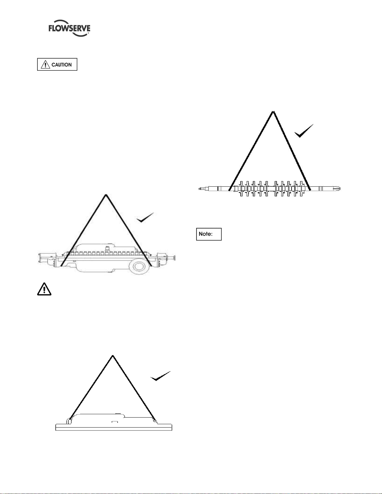
To avoid distortion, the pump unit
should be lifted as shown.
TRAINED PERSONNEL
A crane must be used for all pump sets in excess
of 25 kg (55 lb). Fully trained personnel must
carry out lifting, in accordance with local
regulations. The driver and pump weights are
recorded on their respective nameplates or mass
plates.
2.3.1 Lifting equipment
The following information regarding lifting is
only offered as a general guideline. Flowserve
requires that all lifting and rigging be performed in
accordance with specifications set forth in Chapter 2,
Lifting and Rigging from API Recommended
Practices 686/PIP REIE 686, First Edition.
EQUIPMENT CAPACITY
Make sure that any equipment used to lift the
pump or any other of its components is capable
of supporting the total weight encountered. Make
sure that all parts are properly rigged before
attempting to lift.
Page 10 of 60
Page 11
DMX/DMXD/DMXH/DMXDH USER INSTRUCTIONS ENGLISH 85392728 - 10/09
2.3.2 To lift unit
The complete unit with pump, driver
and auxiliary equipment all mounted on the baseplate
can NOT be lifted as a unit. Driver must be removed
from baseplate before lifting. To lift unit sling
baseplate from all lifting eyes. Failure to do this may
result in permanent deformation of baseplate.
Damage to baseplate caused by mishandling or
improper setting prior to grouting is not covered by
Flowserve’s warranty.
2.3.3 To lift driver
Refer to driver manufacturers instructions.
2.3.4 To lift pump
Install sling from overhead hoist and under bearing
housing mounting brackets (cast portion of casing
where bearing housings attach).
To lift the pump bottom half casing, slings can be
attached to the pump feet, casing boltholes or
padded slings can be used around the outer casing.
2.3.6 To lift pump rotor
Using slings that will not damage shaft, rig around
shaft close to the impellers and to overhead hoist.
Carefully lift rotor from lower half casing.
Proper lifting practice for pump
2.4 Extended storage
Proper lifting practice for pump
LIFTING PRACTICE
Do not lift entire pump from cast lifting lugs on
upper half casings. These lugs are for lifting
upper half casing only.
2.3.5 To lift half casing
To lift upper half casing, rig to overhead hoist from
cast lifting lugs provided.
Proper lifting practice for upper case
The following information regarding
receiving is only offered as a general guideline.
Flowserve requires that all receiving be conducted in
accordance with specifications set forth in Chapter 3,
Jobsite Receiving and Protection from API
recommended Practices 686/PIP REIE 686, First
Edition.
During extended periods of storage prior to
installation and from the time of installation until
commercial operation, precautions must be taken to
protect the pump from deterioration. The various
parts of the pump are protected prior to shipment by
applying varying grades of preservative and paint.
However, during shipment and handling, the
preservatives are subjected to conditions that can
cause their removal. Also, during extended periods of
time, the preservatives may deteriorate. The following
procedures should be followed to prevent
deterioration of the pump during the extended
storage period. These procedures may also be
supplemented by the experience of the person(s)
performing the tasks.
It should be noted, that unless otherwise agreed to,
full responsibility and costs associated with the
storage and inspection of this equipment rests with
the customer.
Page 11 of 60
Page 12

DMX/DMXD/DMXH/DMXDH USER INSTRUCTIONS ENGLISH 85392728 - 10/09
If pump is equipped with a mechanical
seal and is stored or has not been run for 1 year or
more, the mechanical seal must be removed before
start-up and faces re-lapped to guard against the
possibility of seal leakage. When reinstalling the seal,
new “O” rings and gaskets must be used.
2.4.1 Pump inspection upon arrival
When the pump is received, it should be inspected
for damage or other signs of rough handling. Any
damage if found should be reported to the carrier
immediately.
Inspect the preservative coating on the various parts.
If necessary, renew the preservative in areas where it
has rubbed off or scraped.
Inspect all painted surfaces. If necessary, touch up
the areas where paint has been chipped or scraped.
Inspect all covers over pump openings and piping
connections. If covers or seals for the covers are
damaged or loose, they are to be removed, and a
visual inspection made of the accessible interior
areas for accumulation of foreign materials or water.
If necessary, clean and re-coat the interior parts with
preservative to restore the parts to the “as shipped”
condition. Install or replace covers and fasten secure.
2.4.2 Storage area
When selecting a storage area, the following should
be taken into consideration:
a) The deterioration of the equipment will be
proportionate to the class/type of storage
provided.
b) The expenses involved in restoring the
equipment at time of operation will be
proportionate to the class/type of storage
provided.
2.4.3 Storage preferred (dry)
If at all possible, the pump and its components
should be stored indoors where they will be protected
from the elements. If it is not possible to store the
pump and its components indoors, precautions must
be taken to protect them from the elements.
Regardless of whether storage is inside or outside,
the storage area should be vibration-free. All boxes
that are marked for inside storage must be stored
indoors. Coverings of heavy gauge plastic sheets,
canvas, waterproof burlap or other suitable coverings
should protect the pump and its components from
dirt, dust, rain, snow or other unfavorable conditions
when stored outdoors.
All equipment must be placed upon skids or blocks to
prevent contact with the ground and surface
contaminants. Equipment must be adequately
supported to prevent distortion and bending.
2.4.3.1 Rotor storage
It is recommended that pump rotor be removed from
pump and stored vertically. Rotors may also be
stored horizontally in the pump. Rotors that have to
be stored horizontally outside the pump must be
supported close to impeller to eliminate sag that may
cause rotor to take a permanent set.
2.4.3.2 Customer inspection
The stored equipment is to be placed on a periodic
inspection schedule by the customer.
The responsibility for setting up an
inspection and maintenance schedule rests with the
customer and will be dependent upon the class/type
of storage provided. It will be expected that initially
inspection would occur weekly, then depending upon
the inspection reports being favorable or unfavorable,
inspection would continue weekly, monthly, or
quarterly, as may be determined. Inspection reports
must be kept on file.
Every inspection should consist of a general surface
inspection.
a) Pump supports are firmly in place.
b) Pump covers over openings are firmly in place.
c) Pump coverings, plastics or tarps, are firmly in
place. Any holes or tears must be repaired to
prevent entrance of dirt or water.
d) Pump covers are periodically removed from
openings and interior accessible areas inspected.
If surface rusting has occurred, clean and repaint
or re-coat with preservative.
e) If rusting occurs on exterior surfaces, clean and
repaint or re-coat with preservative.
f) Loosen casing drain plugs to allow seepage of
any accumulated moisture.
g) If the rotor is stored horizontally, rotate pump
rotor 1-1/4 revolutions at least once a month to
prevent rotor from taking a permanent set.
Page 12 of 60
Page 13

DMX/DMXD/DMXH/DMXDH USER INSTRUCTIONS ENGLISH 85392728 - 10/09
Make sure bearings have adequate
lubrication before turning rotor.
The oil inlet blanking plates should be
removed and a small amount of oil injected into the
bearings before turning. Refit blanking plates.
h) Periodically remove bearing covers and inspect
for accumulation of moisture, rust and foreign
material. As required, clean bearings and bearing
housing and re-preserve. Install bearing cover
and secure to assure maximum protection.
Bearings removed for storage should be coated
with preservative, wrapped in oil/wax paper, and
stored in a warm dry area.
i) Check individually wrapped parts for signs of
deterioration. If necessary, renew preservative
and wrapping.
If storage is over one month,
Instrumentation (Controls, Electrical devices,
Temperature switches) should be removed and
placed in a climate control environment if
Instrumentation is not powered up.
2.4.3.3 Prior to installation maintenance
Six months prior to the scheduled installation date, a
Flowserve representative is to be employed to
conduct an inspection. All costs involved during
inspection, dismantling, restoration, replacement of
parts, and reassembly will be the responsibility of the
customer. The customer will supply all necessary
labor, tools, and cranes. This inspection will include
(not necessarily in its entirety) but not be limited to
the following:
a) An inspection of all periodic inspection records as
kept on file by the customer, and all inspection
reports that have been compiled during the
storage period.
b) An inspection of the storage area to determine
the “as stored” condition of the equipment prior to
any protection being removed.
c) An inspection of the equipment with protection
covers and flange covers removed.
d) Depending upon the length of time the equipment
was stored, the class/type of storage provided,
(i.e.: indoor, heated, unheated, ground floor,
concrete floor, out-of-doors, under roof, no roof,
waterproof coverings, on concrete, on ground)
and as a result of the inspection of a, b and c
above, Flowserve representative may require a
partial or complete dismantling of the equipment.
e) Dismantling may necessitate restoration of
painted or preserved surfaces, and/or
replacement of gaskets, “O” rings and
mechanical seal and bearings. Use only
Flowserve recommended replacement materials.
Upon completion of the inspection, the Flowserve
representative shall submit a report to the Customer,
and to the Manager of Customer Service, stating in
detail the result of the inspection.
If there are any discrepancies identified, it is the
customer's responsibility for correction before initial
startup.
2.4.4 Storage non-preferred (wet)
It is not recommended that the rotor be subjected to
extended periods of submergence or wetting prior to
start-up. However, it is recognized that in some
cases, a long period of time may lapse from
installation until commercial operation.
If the pump must be stored after being installed and
wetted, the following inspection and maintenance
should be performed.
• Isolate the pump with valving - tag (seal) all
valves.
• Preserve the pump internals.
If storage is over one month,
Instrumentation (Controls, Electrical devices,
Temperature switches) should be removed and
placed in a climate controlled environment if
Instrumentation is not powered up.
Electric motors (pump driver) should
not be stored in damp places without special
protection (refer to motor manufacturer’s
instructions).
2.4.4.1 Corrosive pumpage.
Fill entirely the pump with an approved preservative
such as #2004-Chempagard 9 from Chempak. The
pump should be filled to highest level possible,
affording the greatest protection possible to all
internal parts of the pump.
Page 13 of 60
Page 14

DMX/DMXD/DMXH/DMXDH USER INSTRUCTIONS ENGLISH 85392728 - 10/09
This solution, when drained, will result in a thin
residual oil film (less than 0.0127 mm (0.0005 in.)) on
all internals after the water has evaporated. This
residue provides added corrosion protection until
pump is again filled with liquid or put into service.
Pump cannot be fully drained. Volutes in
the lower half cannot be drained below the bottom of
the main casing bore.
2.4.4.2 Non-corrosive pumpage.
Fill pump with pumpage to the highest level possible.
Open periodically drain connection to drain off any
moisture that may have accumulated. Refill to highest
level possible. Drain and inspect pump prior to startup.
a) Rotate pump rotor 1-1/4 revolutions at least once
a month.
Make sure bearings have adequate
lubrication before turning rotor.
b) Periodically remove bearing covers and inspect
for accumulation of moisture, rust and foreign
material. As required, clean bearings and bearing
housing and re-preserve. Install bearing cover
and secure to assure maximum protection.
2.4.4.3 Painting and preservation
Paints and preservatives used are either Flowserve
standard or special as required by the contract
specification. Refer to 2.1.3, Paint/Rust Preventive for
the description of paints and preservatives used in
this order or contact the branch office through which
the order was placed.
2.5 Recycling and end of product life
At the end of the service life of the product or its
parts, the relevant materials and parts should be
recycled or disposed of using an environmentally
acceptable method and local regulations. If the
product contains substances which are harmful to the
environment, these should be removed and disposed
of in accordance with current regulations. This also
includes the liquids and or gases in the "seal system"
or other utilities.
specifications must be in accordance with the current
regulations at all times.
Make sure that hazardous substances or
toxic fluids are disposed of safely and that the correct
personal protective equipment is used. The safety
Page 14 of 60
Page 15
DMX/DMXD/DMXH/DMXDH USER INSTRUCTIONS ENGLISH 85392728 - 10/09
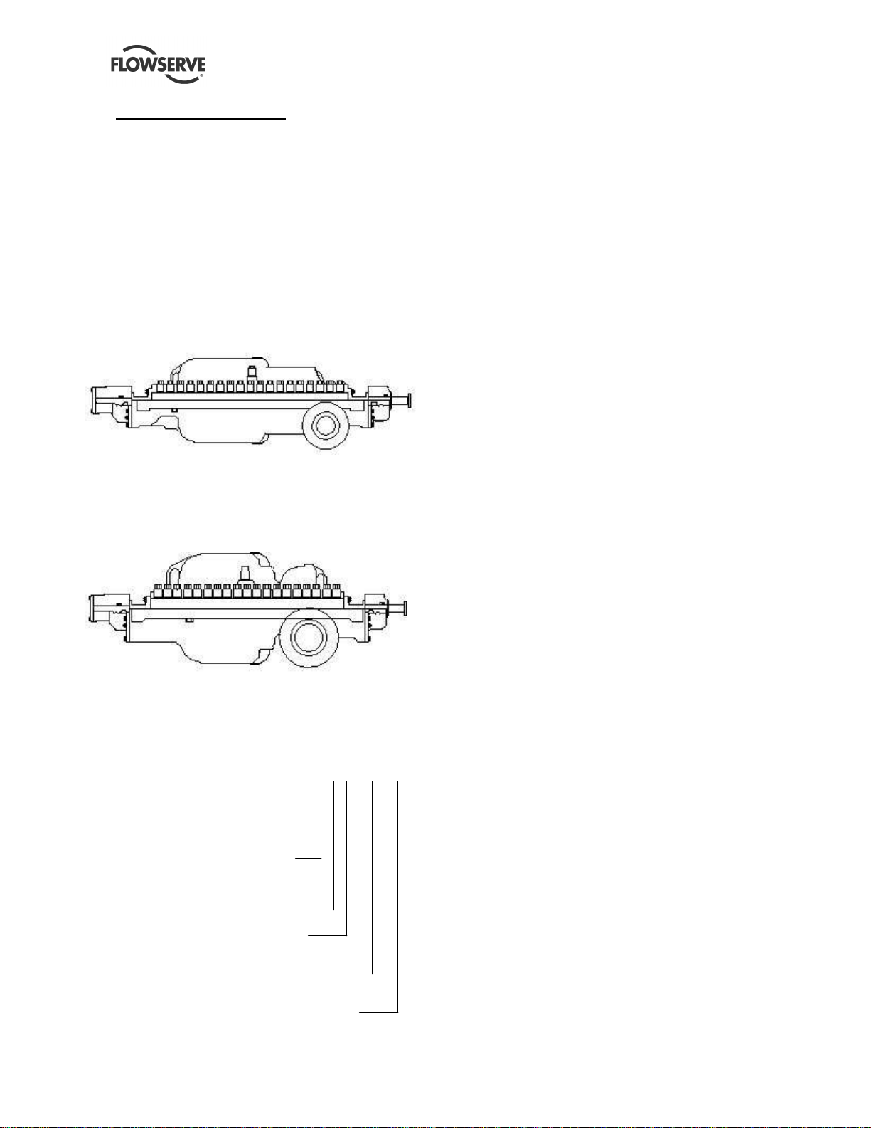
3 PUMP DESCRIPTION
The “DMX” is a multistage single or double suction,
opposed impeller, horizontally split volute pump.
The suction and discharge nozzles are cast integral
with the lower half casing. Rotating parts are
accessible by removing the upper half casing, which
can be removed without breaking suction and
discharge piping.
3.1 Configurations
The DMX can have the following configurations:
3.1.1 Single suction
Single suction configuration
Single suction impeller at first stage (DMX)
3.1.2 Double suction
Double suction configuration
Double suction impeller at the first stage (DMXD)
3.2 Name nomenclature
The pump nomenclature is: 3X10DMX10
The 3 is the pump discharge size
The X is the separator
The 10 is the nominal impeller size
The DMX is pump type
The 10 is the number of stages and depending
on pump size, they go from 2 to 14 stages
DMX= Single suction standard pressure
DMXD = Double suction standard pressure
DMXH = Single suction high pressure
DMXDH = Double suction high pressure
3.3 Design of major parts
3.3.1 Casing
The casing provides for immediate containment of
the liquid being pumped, while directing the flow of
liquid from the suction nozzle to the impellers and
subsequently through the volute to the discharge
nozzle.
The casing halves are sealed by the use of a gasket
and are joined together by studs, which are installed
in the lower half casing and fastened with washers
and cap-nuts.
3.3.2 Impellers
The series’ impellers are single suction, enclosed
type, and one-piece construction and are dynamically
balanced. They are fitted with renewable impeller
rings (front and back), which are held in place by
headless set-screws.
The impellers are keyed and have a shrink fit to the
pump shaft. They are held in axial position by a split
ring.
3.3.3 Casing rings
Casing rings are positioned over the impeller front
rings. These rings are tubular and renewable.
3.3.4 Channel rings
Renewable cast channel rings are positioned over
the impeller back rings. They divide the casing into
stages. These rings are horizontally split and are held
together by shoulder screws or dowel pins.
3.3.5 Center sleeve
A renewable type center sleeve is used under the
center bushing. The center sleeve is tubular and
keyed to the shaft (via the impeller key).
3.3.6 Center bushing
The renewable center bushing is horizontally split,
and the two halves are held together by socket head
cap screws and taper dowel pins. It is held in position
by the raised annular ring of the bushing engaging
the annular groove in the casing. The center bushing,
in conjunction with center sleeve, divides the casing
at the center (back to back) impellers.
Page 15 of 60
Page 16

DMX/DMXD/DMXH/DMXDH USER INSTRUCTIONS ENGLISH 85392728 - 10/09
3.3.7 Throttling sleeve
Renewable type throttling sleeve is used under the
throttling bushing. The throttling sleeve is tubular,
keyed, has a shrink fit to the shaft, and is held in
position by a split ring.
3.3.8 Throttling bushing
Renewable type throttling bushing is used. It is held
in position by the raised annular ring of the bushing
engaging the annular groove in the casing. The
throttling bushing, in conjunction with the throttling
sleeve, allows pressure to be bled off through the
balance line, so that pressure on the Seal Chambers
is balanced. The throttling bushing also balances the
axial thrust of the pump rotor.
3.3.9 Crossover sleeve
A renewable type crossover sleeve under crossover
bushing is only used on double suction pumps
(DMXD/DMXDH). The crossover sleeve is tubular,
keyed, has a shrink fit to the shaft, and is held in
position by a split ring.
3.3.10 Crossover bushing
A renewable type crossover bushing is only used on
double suction pumps (DMXD/DMXDH). The
crossover bushing is horizontally split, and the two
halves are held together by taper dowel pins. It is
held in position by the raised annular ring of the
bushing engaging the annular groove in the casing.
The crossover bushing, in conjunction with crossover
sleeve, controls the leakage between the first and
second stage impellers.
3.3.11 Shaft
The high strength shaft is ground over its entire
length to close tolerances. The shaft is designed to
transmit the required power without vibration and is
stepped at each impeller fit for ease of assembly and
disassembly.
3.3.12 Bearings
The sleeve bearings are carbon steel backed, babbitt
lined, sleeve type insert bearings. The renewable
bearing inserts are mounted in bearing housings kept
from rotating by means of stop pins.
Each bearing is lubricated by an external pressure
supply system.
The thrust bearing is of the titling type with pads on
each side of the shaft mounted thrust
collar. It is capable of transmitting the thrust load in
either direction. It is lubricated from the
pressure lubrication system.
3.3.13 Seal Chambers
The Seal Chambers are cast integral with the casing.
Your pump is typically shipped with the mechanical
seal already installed.
The mechanical seal is designed to suit each
application. This creates the correct seal loading
face when seal gland is bolted in place.
Cartridge type mechanical seals are preset at the
seal manufacturer’s facility and require no field
settings. The seal installation should be checked
before startup.
Refer to the mechanical seal manufacturers drawing
and instructions found in section 8 of this manual for
detailed information.
3.4 Performance and operating limits
Refer to section 10.4 Customer Data Sheet.
Page 16 of 60
Page 17

DMX/DMXD/DMXH/DMXDH USER INSTRUCTIONS ENGLISH 85392728 - 10/09
4 INSTALLATION
The installation/commissioning of this
equipment must be conducted in accordance with
API Recommended Practices 686/PIP REIE 686 First Edition.
Copies of API Recommended ‘Practices’ 686/PIP
REIE 686 - First Edition may be obtained from
America Petroleum Institute
1220 L Street, N.W.
Washington, D.C. 20005.
Telephone: (202) 682-8000.
4.1 Location
Install the unit close to the source of the liquid to be
pumped.
Equipment operated in hazardous locations
must comply with the relevant explosion protection
regulations. See section 1.6.4, Products used in
potentially explosive atmospheres.
When selecting the location, be sure to allow
adequate space for operation as well as for
maintenance operations involving dismantling and
inspections of parts.
Headroom is an important consideration as an
overhead lift of some type is required.
4.2 Foundation
The following information regarding
foundation is only offered as a general guideline.
Flowserve requires that all foundations be designed
and installed in accordance with specifications set
forth in Chapter 4, Foundations from API
Recommended Practices 686/PIP REIE 686, First
Edition.
The design of foundation is not the responsibility of
Flowserve. It is therefore recommended that the
customer consult a competent specialist skilled in the
field of foundations, to insure proper
design/installation of the foundation.
The foundation should be properly prepared
according to the planned grouting method. See 4.3
Grouting for details.
The foundation should be rigid and substantial to
support the baseplate at all points to prevent any
pump vibration and to permanently.
The most satisfactory foundations are made of
reinforced concrete. These should be poured well in
advance of the installation to allow proper time for
drying and curing.
The General Arrangement Drawing will show
required anchor bolt locations and size of bolts.
Allow a little more than the specified threaded bolt
length above the rail of the baseplate. The excess
can always be cut off if it is not needed.
A clean rough-finish top surface is required when
applying grout.
4.2.1 Installation check list
a) Level Baseplate.
b) Preliminary Alignment.
c) Grout Baseplate - Check Foundation Bolts
d) Alignment Shaft/Coupling.
e) Piping installed – correct vent, gauge, valve,
suction strainer and pipe support locations?
f) Check Coupling Alignment.
g) Coupling guard correctly installed?
4.2.2 Level the baseplate
The following information regarding leveling
of equipment is only offered as a general guideline.
Flowserve requires that all leveling of equipment be
performed in accordance with specifications set forth
in Chapter 5, Mounting Plate Grouting from API
Recommended Practices 686/PIP REIE 686, First
Edition.
Before putting the unit on the foundation, thoroughly
clean the top of the foundation. Break off any loose
pieces of cement and roughen the top with a chisel to
afford a good hold for grout.
When lifting baseplate with pump, sling
baseplate from all lifting eyes provided. Failure to do
Page 17 of 60
Page 18

DMX/DMXD/DMXH/DMXDH USER INSTRUCTIONS ENGLISH 85392728 - 10/09
this may result in permanent deformation of
baseplate.
Pump, driver auxiliary equipment and
piping shall be removed from the baseplate before
leveling the baseplate.
Locate the baseplate in its proper position on the
concrete block together with the leveling screws as
shown in the General Arrangement Drawing.
Using a precision level across the machined surfaces
of the pump and driver mounting pads, adjust leveling
screws as necessary to ensure that baseplate is
leveled in all directions.
When the baseplate is leveled, snug the foundation
bolts, but do not completely tighten.
4.2.3 Preliminary alignment
Using the previous procedure, adjust baseplate until
pump and driver are within 0.076 mm (0.003 in.).
4.3 Grouting
The following information regarding
grouting is only offered as a general guideline.
Flowserve requires that all grouting be installed in
accordance with specifications set forth in Chapter 5,
Mounting Plate Grouting from API Recommended
Practices 686/PIP REIE 686, First Edition. Refer to
API 610 - Eighth Edition - Appendix `L` for baseplate
grouting requirements. It is recommended that the
customer consult a competent specialist skilled in the
field of grouting, to insure the proper installation of all
grouting.
The following ASTM Specifications are furnished as
references for test methods used in conjunction with
installation of grouting materials and should be used
to obtain proper results:
ASTM C 78-84, Test Method for Flexural Strength for
Concrete
ASTM C 109-90, Test Method for Compressive
Strength of Hydraulic Cement Mortars – Modified
ASTM C 469-87a, Test Method for Static Modulus of
Elasticity and Poisson’s Ratio of Concrete in
Compression
ASTM C 496-90, Test Method for Splitting Tensile
Strength of Cylindrical Concrete Specimens
ASTM C 531-85, Test Method for Linear Shrinkage
and Coefficient of Thermal Expansion of Chemical
Resistant Grouts and Monolithic Surfacing - Modified
ASTM C 666-90, Test Method for Resistance of
Concrete to Rapid Freezing and Thawing
ASTM C 939-87, Test Method for Flow of Grout for
Preplaced Aggregate Concrete (Flow Cone Method)
ASTM C 942-86, Test Method for Compressive
Strength of Grouts for Preplaced Aggregate Concrete
in the Laboratory
ASTM C 1090-88, Test Method for Measuring
Changes in Height of Cylindrical Specimens from
Hydraulic Cement Grout
ASTM C 1107-91, Standard Specification for
Packaged Hydraulic-Cement Grout (Non-Shrink)
(CRD-C 621-92), ACI 351, Grouting for Support of
Equipment and Machinery
24-Hour Test, MBT Test Method for Grout
Performance
Minimum requirements for epoxy grout
(typical properties at 23 oC (73 oF))
ASTM D-635, Fire Resistant
ASTM C-579B, Minimum Compressive Strength –
12000 psi
ASTM C-827, Height Change @ 38 oC (100 oF) –
Positive – Effective Bearing Area – 95%
ASTM C-1181, Maximum Creep in 1 Year –
1.6X10
-3
in./in. at 140 oF, 400 psi
ASTM C-307, Minimum Tensile Strength – 12.4 Mpa
(1800 psi)
ASTM C-580, Minimum Flexural Strength – 26.2 Mpa
(3800 psi)
ASTM C-580, Minimum Flexural Secant Modulus –
1.2X10⁴ Mpa (1.8X10⁶ psi)
ASTM C-531, Maximum Coefficient of Expansion –
-6
17X10
in./in./oF. Maximum Peak Exotherm 1000 g
(35.27 oz.) insulated – 35 oC (95 oF). Full Aggregate
Must Be Used.
Page 18 of 60
Page 19

DMX/DMXD/DMXH/DMXDH USER INSTRUCTIONS ENGLISH 85392728 - 10/09
30-40 mm
25 –
50 mm unless
Normal concrete
30-40 mm
a
c
b
NOT FINISH WITH TROWEL
CONCRETE
4.3.1 Grouting material
4.3.1.1 Normal grout material
A quality, high strength, non-shrink cementatious
grout material shall be used for installation. Epoxy is
preferred.
4.3.1.2 Layered grout material
A layered combination of non-shrink cementatious
grout and normal industrial concrete can be used.
See sketch below for example.
a) The first layer shall be 25 – 50 mm plus a layer of
30 - 40 mm of normal grout material as described
in 4.3.1.1.
b) The second layer is normal industrial concrete
poured to a level that is approximately 30-40 mm
from the top of the baseplate decking.
c) The top layer is 30-40 mm normal grout material
as described in 4.3.1.1.
as specified
4.3.2 Grouting method A
a) Prepare the foundation properly as specified in
sketches below.
BOLT
PIPE
WASHER
ALLOW BOLTS TO PROJECT
FOR GROUTING UNDER
BASEPLATE
MAKE THIS
DISTANCE
EQUAL TO LUG
ON BASEPLATE
ALLOW AMPLE
THREADED BOLT
LENGTH ABOVE
ROUGH FINISH
FOR GROUT
ROUGH CONCRETE
STUFF WASTE AROUND
BOLT WHILE POURING
PIPE SLEEVE TO BE
THREE TIMES
DIAMETER OF ANCHOR
BOLT
WELD A LARGE
WASHER WITH LUGS
TO THE BOTTOM OF
BOLT & PIPE SLEEVE
TO PREVENT
TURNING
Foundation complete description
b) Build a dam around the foundation to contain
grout materials.
Before grouting, check level of
machined pads of baseplate in both directions and
perform a rough shaft/coupling alignment. Alignment
after grout has set will not be possible if above is not
satisfactorily completed.
c) Grout leveling space and baseplate as per
manufacturer's instructions.
Holes are provided in the baseplate to permit
pouring the grout and distributing. Vent holes are
also provided in each compartment. Fill under the
baseplate completely, stirring to assure proper
distribution of the grout. Check to see that the
grout flows under the edges of the baseplate
evenly.
LEAVE TOP OF
FOUNDATION ROUGH DO
FINISHED
GROUTING
DAM
Template for hanging foundation bolts
The sketch illustrates a recommended foundation
bolt arrangement. Notice the large washer with
lugs at the bottom. It should be welded to the bolt
and pipe sleeve to prevent turning.
Building dam around the foundation before pouring
grout
Page 19 of 60
Page 20

DMX/DMXD/DMXH/DMXDH USER INSTRUCTIONS ENGLISH 85392728 - 10/09
SCREW
Pour grout until level reaches top of dam.
Allow drying sufficiently to prevent grout from
overflowing while completing the remaining grouting.
Do not vibrate baseplate when grouting;
make sure baseplate is vented properly and all areas
indicated on General Arrangement drawing are
thoroughly filled to prevent any resonant problems.
d) When the grout is thoroughly hardened, remove
the dam.
e) Completely tighten the foundation bolts.
4.3.3 Grouting method B
a) Prepare foundation properly as shown in the
General Arrangement Drawing. The bolt holes
shall be tapered to the top.
GROUT
BASEPLATE
LEVELING
FOUDNATION
CONCRETE
FOUNDATION BOLTS
GROUT LEVELING
SPACE
GROUT BOLT HOLES
Foundation and grouting description
b) Build a dam around the foundation to contain
grout materials.
c) Grout the foundation bolt holes as per
manufacturer's instructions, ensure that the grout
fills all open space and eliminates all air pockets.
Before grouting leveling space and
baseplate, check level of machined pads of baseplate
in both directions and perform a rough shaft/coupling
alignment. Alignment after grout has set will not be
possible if above is not satisfactorily completed.
d) Grout leveling space and baseplate as per
manufacturer's instructions.
Holes are provided in the baseplate to permit
pouring the grout and distributing. Vent holes are
also provided in each compartment. Fill under the
baseplate completely, stirring to assure proper
distribution of the grout. Check to see that the
grout flows under the edges of the baseplate
evenly.
Pour grout until level reaches top of dam.
Allow drying sufficiently to prevent grout from
overflowing while completing the remaining grouting.
Do not vibrate baseplate when grouting;
make sure baseplate is vented properly and all areas
indicated on General Arrangement drawing are
thoroughly filled to prevent any resonant problems.
e) When the grout is thoroughly hardened, remove
the dam.
f) Completely tightened the foundation bolts.
4.4 Initial alignment
4.4.1 Shaft/coupling alignment
The following information regarding shaft
alignment is only offered as a general guideline.
Flowserve requires that all shaft alignment be
performed in accordance with specifications set forth
in Chapter 7, Shaft Alignment from API
Recommended Practices 686/PIP REIE 686, First
Edition.
Shaft alignment must be correct for
successful operation. Rapid wear, noise, vibration
and actual damage to the equipment may be caused
by shaft misalignment. The shafts must be aligned
within the limits given within this section.
Adjustment to correct the alignment in one
direction may alter the alignment in another direction.
Always check in all directions after making any
adjustment.
Coupled equipment must be aligned to minimize
unnecessary stresses in shafts, bearings and
coupling. Flexible couplings will not compensate for
appreciable misalignment. Foundation settling,
thermal expansion or nozzle loads resulting in
baseplate/foundation deflection and vibration during
Page 20 of 60
Page 21

DMX/DMXD/DMXH/DMXDH USER INSTRUCTIONS ENGLISH 85392728 - 10/09
DRIVER SIDE
DRIVER SIDE
operation may require the full coupling misalignment
capability.
4.4.1.1 Types of misalignment
There are two types of shaft misalignment: Angular
and offset. Both types of misalignment can occur in
horizontal and vertical planes and are present in most
applications.
In angular misalignment, the centerline of the shafts
intersects, but is not on the same axis.
PUMP SIDE
Angular misalignment
In offset misalignment, the shaft centerlines are
parallel but do not intersect.
Offset misalignment
Combined misalignment
4.4.1.2 Alignment methods
The following methods may be used to align
equipment train. The methods a) and b) are dial
indicator based.
a) Rim and face alignment
Rim and face alignment
b) Reverse rim indicator alignment
PUMP SIDE
Reverse rim indicator alignment
c) Laser alignment.
4.4.2 Dial-indicator-based alignment
4.4.2.1 Check soft foot
Soft foot can affect the alignment readings and
should be checked first and eliminated on both pump
and driver.
a) Tighten hold down bolts.
b) Set a dial indicator on one foot, loosen the bolt
and check if there is a indicator reading. If so
place a shim with the same thickness as the
displacement.
c) Check and adjust all feet.
Page 21 of 60
Page 22

DMX/DMXD/DMXH/DMXDH USER INSTRUCTIONS ENGLISH 85392728 - 10/09
4.4.2.2 Set DBSE
The shaft gap, or distance between shaft ends
(DBSE), must be in accordance with the certified
General Arrangement Drawing and must be
measured with pump and driver shafts in the center
of their axial end float. Motor with sleeve bearings is
to be aligned with rotor at magnetic center.
Move driver to insure proper gap distance.
It is recommended that the pump holddown bolting be torqued before taking any alignment
measurements. This makes the pump the fixed
machine and the driver the movable machine. In
certain cases, however, it may be impractical to move
the driver; therefore, the pump may have to be
moved.
4.4.2.3 Determine bracket sag
Bracket sag must be determined and included in the
alignment calculation.
a) Install clip with extension pieces and dial
indicator(s).
b) Place indicator on top and reset to zero, turn
180° and read indicator and register.
c) Record sag reading obtained at the bottom.
d) Side to side readings need not to be corrected as
the sag is equal on both sides.
4.4.2.4 Determine misalignment and correct
vertical plane
Before moving the equipment vertically, it is important
that the vertical thermal expansion be taken into
consideration. Refer to General Arrangement
Drawing notes and/or driver instructions for
recommended cold vertical setting (if thermal
expansion is a factor).
The shims between the motor feet and mounting
surface should be clean and dry. This is especially
critical for equipment that has been in service for
some time and need to be realigned. Water, dirt and
rust may change the height of the shim pack over a
period of time. Shims should be made large enough
to support the weight of the motor on its mounting
foot. Do not use many thin shims, as this may result
in a spongy mounting.
Recommended shim design
Move the equipment vertically by adding or removing
the calculated thickness of shims. Torque equipment
hold-down bolting to required values.
4.4.2.5 Determine misalignment and correct
horizontal plane
The dial indicators shown below are required to
accurately measure the move in the horizontal
direction. Move the driver by bumping with soft
hammer/mallet or using the jack-screws (if provided).
The amount of horizontal relocation required is
calculated in alignment data sheet.
TOP VIEW
COUPLING
DIRECTION OF SHAFT
DIAL INDICATORS
AT DRIVER FEET
DRIVER
(MOVABLE)
Dial indicators configuration
It is recommended, the completed
alignment document be retained as part of your
permanent maintenance file.
4.4.3 Laser alignment
The use of laser alignment greatly simplifies the
alignment process. Because of equipment and
software differences, this will only describe laser
alignment in general steps.
a) Prior to alignment process the baseplate must be
leveled.
b) Check for soft foot condition. Uneven base
height, dirty or corroded foot or other irregularities
c) Rough align the pump and motor shafts with a
straight edge.
Page 22 of 60
Page 23

DMX/DMXD/DMXH/DMXDH USER INSTRUCTIONS ENGLISH 85392728 - 10/09
CLEARANCE
d) Mount the laser emitter on the pump shaft, and
the laser target on the motor shaft.
e) Link the shaft ends so they rotate together.
f) Adjust shim stack heights for vertical parallelism
and angular alignment per laser unit’s output.
Make the necessary corrections by adding or by
removing shims at the motor feet.
g) Adjust the motor position sideways for horizontal
and angular alignment per the laser unit’s output
by using a soft mallet or adjusting screws.
h) Tighten all pump and motor feet fasteners.
i) Verify the final alignment
4.4.4 Check coupling alignment
The angular and offset coupling alignment must be
rechecked.
a) Coupling faces are to be parallel within
0.0254 mm (0.001 in.) TIR.
b) Coupling outside diameters is to be aligned within
0.0762 mm (0.003 in.) TIR.
c) Motor-Driven: “Bump” the motor and check motor
rotation.
d) Turbine-Driven: Check turbine rotation. (If wrong,
consult turbine manufacturer.)
4.4.5 Assemble coupling
a) Assemble coupling per the manufacturer's
instructions included in Section 8 of this manual.
b) Install coupling guard.
4.4.6 Dowel pump and driver
a) Cold Pumps (temperature below 93 °C (200 °F))
Pump hold down bolts are to be torqued to the
proper value and dowel pins put in two diagonally
opposite feet.
b) Hot Pumps
Pumps handling liquids at temperatures of 94 °C
(200 °F) and over are designed to permit the casing
to expand with temperature away from coupling end
of pump. The units that come under this classification
must have the pump support feet dowelled to the
pedestal at the coupling end. This maintains the
coupling gap at the desired amount.
The pump feet at the opposite end are held from
moving vertically by the use of a self-locking nut. The
clearance between the base of the nut and the top of
the pump foot should be 0.051 mm (0.002 in.).
A “Gib Block” running parallel to the length of the
pump foot at each of the outboard feet controls the
horizontal movement. The "Gib Blocks" are bolted
and doweled to the pedestal. A 0.254 mm (0.010 in.)
gap is maintained between the "Gib Block" and pump
foot.
The self-locking nuts, which hold the pump
from moving in a vertical motion, are clamped
tight to the pump foot at time of shipment. The
0.051 mm (0.002 in.) clearance must be
established at time of installation.
DOWEL PIN (TYP)
BASEPLATE
PEDESTAL
FLEX LOCK NUT
GIB
BLOCK
PUMP
FOOT
BASEPLATE
PEDESTAL
0.002"
GIB
BLOCK
0.010"
Gib block installation sketch for hot pump
c) Pump Driver
Refer to General Arrangement Drawing and/or driver
instructions for doweling information.
4.4.7 Gib block installation for hot applications
Gib blocks are installed to control the direction of the
growth while maintaining pump-driver coupling
alignment. They are installed after baseplate has
been leveled and grouted, suction and discharge
piping connected, and final shaft coupling alignment
is completed.
Gib blocks are shipped loose and field installed at the
site. The following procedure must be followed for
correct installation of gib blocks.
a) Fully torque the hold-down bolts in the driver end
of pumps feet to torque values listed in the
instruction manual (refer to Sectional Assembly
Drawing in section 8).
Page 23 of 60
Page 24

DMX/DMXD/DMXH/DMXDH USER INSTRUCTIONS ENGLISH 85392728 - 10/09
b) Install the dowel pins in the pump drive end foot
by drilling the foot and the baseplate for the
tapered dowel provided.
c) Position the gib blocks to obtain a 0.254 mm
(0.010 in.) clearance between the gib block and
the side of the non-drive end pump foot as noted
on the attached figure. Drill and tap the cap
screw holes for the gib blocks.
d) Tighten the hold-down bolts for the gib blocks.
e) Install the dowel pins in the gib blocks by reaming
the block and baseplate for the tapered dowel
provided.
f) Tighten the hold-down locknuts on the non-drive
end pump feet to establish a 0.051 mm
(0.002 in.) gap between the locknut and the
pump foot.
4.4.8 Hot alignment check
A hot check can only be made after the unit has been
in operation a sufficient length of time to assume its
NORMAL operating temperature and conditions. If
the unit has been correctly cold set, the offset
misalignment will be within 0.076 mm (0.003 in.) TIR
and the angular misalignment will be within
0.0254 mm (0.001 in.) TIR when in operation. If not,
make adjustments.
Do not attempt any maintenance,
inspection, repair or cleaning in the vicinity of
rotating equipment. Such action could result in
injury to operating personnel.
Before attempting any inspection or repair
on the pump the driver controls must be in the
"off" position, locked and tagged to prevent
restarting equipment and injury to personnel
performing service on the pump.
4.5 Piping
The following information regarding
piping is only offered as a general guideline to the
customer. Flowserve requires that all piping and
related systems be designed/installed in accordance
with specifications set forth in Chapter 6, Piping from
API recommended practices 686/PIP REIE 686, First
Edition.
The design of piping, and related systems, is not the
responsibility of Flowserve. It is therefore
recommended that the customer consult a competent
specialist skilled in the field of piping, to insure proper
design/installation of all piping.
4.5.1 Suction and discharge piping
These units are furnished for a particular service
condition. Changes in the hydraulic system may
affect performance adversely. This is especially true
if the changes reduce the pressure at the suction or if
the liquid temperature is increased. In case of any
doubt contact the nearest Flowserve Office.
Suction and discharge piping should be of ample
size, be installed in direct runs, and have a minimum
of bends. Eccentric reducer shall be flat on top
(FOT).
It is desirable to have at least seven (7) diameter of
straight pipe between the first elbow and the pump
suction. Elbow in the piping to the pump’s suction
nozzle should be of the long radius type.
Seven (7) diameters of straight pipe should be used
between two elbows in series and the pump suction.
Elbows in more than one plane should not be used
without splitters.
Splitters are placed in the elbow in the mean radius
line perpendicular to the plane of the elbow.
Provision must be made to support
piping external to the pump to prevent excessive
nozzle loads, maintain pump/driver alignment and
avoid pipe- induced vibrations.
Install a check valve and a gate valve in the
discharge pipe of the pump. When the pump is
stopped, the check valve will protect the pump
against excessive pressure and will prevent the pump
from running backward. The check valve should be
installed between the gate valve and the pump
nozzle in order to permit its inspection. The gate
valve is also useful in priming and starting the pump.
Keep the suction pipe short and direct. Use a suction
pipe equal to or one size larger than the pump
suction nozzle. Keep the suction pipe free of all air
pockets.
Page 24 of 60
Page 25

DMX/DMXD/DMXH/DMXDH USER INSTRUCTIONS ENGLISH 85392728 - 10/09
PREFERRED DIRECTION OF FLOW
A spool piece should be installed in suction
line so that the suction screen may be installed and
removed.
Operation at low flows results in pump
power heating the liquid. A bypass may be required
to prevent vaporization and subsequent pump
damage. Mechanical damage may result from
continuous operation at flows less the minimum flow
of design operating point (see 10.4 Customer Data
Sheet).
When pump is equipped with manifolded
vent and drain lines, each line must be equipped
with an individual valve to prevent any liquid from
a high pressure line flowing into a low pressure
line. These valves must be kept in the closed
position during pump operation.
4.5.2 Suction strainer
In a new installation, great care should be taken to
prevent dirt, scale and welding beads from entering
the pump. Even when piping has been previously
flushed, it is difficult to break loose the oxides and
mill scale, which will become free when the pipe
heats and cools several times. Numerous close
running clearances within the pump are vulnerable to
abrasive matter present in new piping. Foreign
material may be large enough, or of sufficient
volume, to jam a pump, with probable damage to
both pump and drive equipment. Smaller size
material passing through the pump can cause rapid
pump wear and premature pump failure.
This pump is provided with the assumption that it will
be pumping clean liquids (unless otherwise stated in
the order and addressed in the proposal). Flowserve
pumps are provided with running clearances ranging
typically from 0.12 mm (0.005 in.) to 0.80 mm
(0.030 in.), depending on the service and the pump
size. It is impractical to install a suction strainer to
remove particulate of this size. Such particles will
normally pass through the pump without causing
damage, provided the concentrations are minor.
The possibility exists that, on shutdown of the pump,
such particles can become trapped in the close
running clearances during coastdown, causing
binding. Flowserve cannot recommend a procedure
that will totally prevent such binding; however, we
strongly suggest that systems be cleaned and
thoroughly flushed prior to connecting the pump to
the piping to minimize particles entering the pump.
Starting and stopping of the pump should be
MINIMIZED, as pumps are most susceptible to dirt
during starts and stops.
In the event that binding on coastdown occurs, it is
unlikely that the binding can be remedied by hand
rolling the rotor, and partial disassembly may be
required to clean the affected parts. It should be
noted that increased particle concentrations increase
the probability of coastdown binding and seizures, as
well as erosion damage.
Excessive force used to try to free a
bound rotor may cause damage beyond minor cleanup and repair of rotor parts.
Generally, a pump should not be installed without
start-up strainer protection. The suction piping
should be thoroughly flushed before installing the
suction strainer and connecting the suction piping to
the pump. The strainer should be installed in the inlet
piping near the pump, making certain that it is located
where it may be readily serviced (cleaned). Be sure,
however, that the installed strainer will not distort the
flow to the pump suction nozzle.
Do not install the strainer directly on the pump
suction nozzle. For a cone-type strainer, the downstream end of the cone should be no closer than four
(4) pipe diameters from the pump suction nozzle.
Basket-type strainers typically introduce greater flow
disturbances and should be installed at least six (6)
pipe diameters from the pump suction nozzle.
The Flowserve standard for suction strainers consists
of conical-shaped steel plate with 1/8 in. perforations
see the below picture. The open area of the strainer
should be a minimum of three times the area of the
pump suction.
At all times when using suction strainers, it is critical
that the pressure drop across the strainer be
constantly monitored to ensure that the pump suction
Page 25 of 60
Page 26

DMX/DMXD/DMXH/DMXDH USER INSTRUCTIONS ENGLISH 85392728 - 10/09
pressure does not fall below that required to prevent
pump cavitation. Pressure (or vacuum) gauges
should be installed on both sides of the strainer so
that the pressure drop across the strainer can be
monitored. During start-up of the system, the gauges
should be monitored continuously. Consult the plant
engineer or system designer for the allowable
pressure differential across the strainer prior to
operating the pump. Pressure differential across the
strainer and/or screen is typically no more than
2 – 3 psig. An increase in the differential pressure
between the two gauges indicates that the strainer or
screen is becoming clogged with dirt and scale.
Before the pressure drop becomes so severe that
cavitation occurs, the pump should be shut down and
the strainer cleaned. Alarm settings to protect the
pump from damaging cavitation and loss of suction
need to be supplied by the plant engineer or system
designer prior to operating the pump. Typical alarm
settings to protect the pump from damaging
cavitation and loss of suction would be 5 psig
differential pressures across the strainer (screen).
The suction piping should be arranged such that the
ultimate strainer configuration (location) allows ready
access for cleaning.
The strainer may be fitted with a finer screen to filter
the inlet flow. When this is done, 40 mesh screens is
typically used for start-up operation, at reduced flow
rates. For final operation in a closed system, the
suction strainers are normally removed after the
system is cleaned. For critical pump applications,
where continuous screening of suction flow is
desirable, and in open systems, 20-mesh screening
is typically used for permanent strainers. At all times,
when using screens and suction strainers, it is
critical that pressure drop across the screen and/or
strainer be constantly monitored to ensure that the
pump suction pressure does not fall below that
required to prevent cavitation.
When dirt and scale have been removed from the
system, as indicated by no further change in pressure
drop across the strainer with time, the start-up
strainer may be removed or the screen may be
replaced with one having larger openings. If a
permanent strainer will be used during normal
operation, the pressure differential needs to be
monitored on a continuous basis.
If a permanent strainer is not used, the start-up
strainer needs to be temporarily reinstalled whenever
the system is opened up for repair or routine
maintenance. As long as a suction strainer or screen
remains in place, the differential pressure should be
monitored on a regular basis.
The pressure drop across the strainer
is a direct reduction in the NPSH available to the
pump. NPSH available must always exceed the
NPSH required by the pump. This requirement may
limit the pump flow rate, particularly during start-up
operation. Alarms or automatic pump shutdown
devices should be installed to minimize the possibility
of pump damage. It is the responsibility of the pump
operator to obtain the allowable pressure drop across
the strainer for safe pump operation from the plant
engineer or system designer prior to operation of the
pump.
4.5.3 Coupling alignment check
Refer to section entitled shaft/coupling alignment and
perform a coupling alignment check as outlined. This
check is recommended to insure the alignment has
not been disturbed during installing suction and
discharge piping.
4.6 Electrical connections
Electrical connections must be
made by a qualified Electrician in accordance
with relevant local national and international
regulations.
It is important to be aware of the EUROPEAN
DIRECTIVE on potentially explosive areas where
compliance with IEC60079-14 is an additional
requirement for making electrical connections.
It is important to be aware of the
EUROPEAN DIRECTIVE on electromagnetic
compatibility when wiring up and installing
equipment on site. Attention must be paid to
ensure that the techniques used during
wiring/installation do not increase
electromagnetic emissions or decrease the
electromagnetic immunity of the equipment,
wiring or any connected devices. If in any doubt
contact Flowserve for advice.
The motor must be wired up in
accordance with the motor manufacturer's
instructions (normally supplied within the
terminal box) including any temperature, earth
leakage, current and other protective devices as
appropriate.
The identification nameplate should be checked
to ensure the power supply is appropriate.
Page 26 of 60
Page 27

DMX/DMXD/DMXH/DMXDH USER INSTRUCTIONS ENGLISH 85392728 - 10/09
A device to provide emergency stopping
must be fitted.
If pre-wired is not supplied to the pump unit, the
controller/starter electrical details will also be supplied
within the controller/starter.
For electrical details on pump sets with controllers
see the separate wiring diagram.
Direction of rotation has to be checked
with pump uncoupled.
4.7 Final shaft alignment check
After connecting piping to the pump, rotate the shaft
several times by hand to ensure there is no binding
and all parts are free.
Recheck the coupling alignment, as previously
described, to ensure no pipe strain. If pipe strain
exists, correct piping.
To prevent excessive surface temperatures at
bearings it is recommended that temperature or
vibration monitoring are carried out.
Refer to section entitled shaft/coupling
alignment and perform a coupling alignment check as
outlined. This check is recommended to insure the
alignment has not been disturbed during the grouting
of the baseplate or while installing suction and
discharge piping.
4.8 Protection systems
The following protection systems are
recommended particularly if the pump is installed in a
potentially explosive area or is handling a hazardous
liquid. If in doubt consult Flowserve.
If there is any possibility of the system allowing the
pump to run against a closed valve or below
minimum continuous safe flow a protection device
should be installed to ensure the temperature of the
liquid does not rise to an unsafe level.
If there are any circumstances in which the system
can allow the pump to run dry, or start up empty, a
power monitor should be fitted to stop the pump or
prevent it from being started. This is particularly
relevant if the pump is handling a flammable liquid.
If leakage of product from the pump or its associated
sealing system can cause a hazard it is
recommended that an appropriate leakage detection
system be installed.
Page 27 of 60
Page 28

DMX/DMXD/DMXH/DMXDH USER INSTRUCTIONS ENGLISH 85392728 - 10/09
5 COMMISSIONING, START-UP,
OPERATION AND SHUTDOWN
Commissioning of all equipment must be
performed in accordance with specifications set forth
in Chapter 9, Commissioning from API
Recommended Practices 686/PIP REIE 686, First
Edition.
These operations must be carried
out by fully qualified personnel.
5.1 Precommissioning procedure
a) Never operate the pump with suction valve
closed.
b) Never operate pump unless it is filled with liquid
and vented.
c) Never operate the pump unless a liquid source is
available.
d) Never operate the pump without proper
lubrication.
5.1.1 Pre-operational checks
At initial start-up and after the equipment has been
overhauled:
a) Ensure pump and piping are clean. Before
putting the pump into operation, it should be
thoroughly flushed to remove the rust preventive
as well as any foreign matter, which may have
accumulated during installation.
Isolate the pump from pipe work, flush out the
pipe work then flush the pump. This operation
must be carried out thoroughly because the
pump contains many close running clearances,
which will be damaged by dirt particles. Take all
possible care not to contaminate your system.
b) Clean and flush bearing housings and lubrication
system. (see pump lubricants).
c) Turn rotor by hand or with strap to make sure it
turns freely.
d) Ensure that the mechanical seal is properly
assembled and tightened.
Most cartridge seals are equipped
with a spacer between the gland plate and drive
collar. This spacer must be removed before starting
unit.
e) Ensure coupling is properly aligned and
lubricated; and pump and driver are properly
doweled. (Refer to shaft /coupling alignment
procedure).
f) Ensure coupling guard is in place.
g) Check torque of all bolting and plugs for
tightness.
5.1.2 Pump instrumentation set points
The following set points apply to DMX Pumps, which
use the sleeve/KTB bearing arrangement.
a) Bearing metal temperature
• Normal 60 oC to 82 oC (140 oF to
180 oF)
• Alarm 85 oC (190 oF)
• Shutdown 90 oC (200 oF)
b) Bearing housing vibration
• Normal 2.5 to 7.6 mm/s (0.1 to
0.3 in./sec)
• Alarm 10.2 mm/s (0.4 in./sec)
• Shutdown 12.7 mm/s (0.5 in./sec)
c) Radial shaft vibration
• Normal 0.025 to 0.050 mm (1 to
2 mils)
• Alarm 0.076 mm (3 mils)
• Shutdown 0.102 mm (4 mils)
5.1.3 Initial start up procedure
a) Close discharge valve if a bypass system is
used. If not, crack open the discharge valve.
b) Prepare the driver for start-up in accordance with
the manufacturer’s instructions.
c) Warm-up pump (if required).
Avoid severe thermal shocks to the pump as a result
of sudden liquid temperature changes. The pump
must be preheated prior to start-up. Unless otherwise
specified, the external temperature of the casing
must be within 55.6 °C (100 °F) of the temperature of
the liquid to be pumped at time of start-up.
Pump temperature stratification could
occur. A maximum temperature delta of 28 °C (50 °F)
between the upper and lower case shall be checked
prior to starting the pump.
Page 28 of 60
Page 29

DMX/DMXD/DMXH/DMXDH USER INSTRUCTIONS ENGLISH 85392728 - 10/09
Due to the heavy metal sections, the casing will lag
the liquid temperature during such changes, and
severe temperature stresses and subsequent
misalignment of machined fits may result. Preheating is accomplished by circulating a small
amount of hot fluid through the casing by utilizing
vents, drains or bypass from discharge and suction.
Preheat pump slowly at a rate not to exceed 55.6 °C
(100 °F) per hour.
d) Prime pump and ensure pump suction valve and
bypass isolating valve are open.
Before starting or while operating the
pump, the casing and suction line must be completely
filled with the liquid being pumped. The rotating parts
depend on this liquid for lubrication, and the pump
may seize if operated without liquid.
e) Ensure pump recirculating line (if provided) is
open and free of obstructions.
f) Check that pump is vented by observing leakage
from casing vent and seal piping vent. Close vent
when liquid is emitted.
g) Make sure seal piping is turned on.
h) Prepare the driver for start-up in accordance with
the manufacturer’s instructions.
i) Check pump rotation by starting unit
momentarily. The direction of rotation is shown
on 10-4, pump data sheet. Note the pump coasts
to a gradual stop.
If pump stops abruptly when driver is
shut down, investigate for pump binding. Take
necessary remedial action before resuming
operation.
j) Starting the driver (motor driven).
k) Starting the driver (turbine driven).
Start the turbine and bring it up to speed quickly.
l) As soon as the pump is up to rated speed, open
discharge valve. This will avoid abrupt changes in
velocity and prevent surging in the suction line.
5.2 Pump lubricants
Operation of the unit without
proper lubrication can result in overheating of the
bearings, bearing failures, pump seizures and
actual breakup of the equipment, exposing
operating personnel to injury.
Oil is supplied to the pressure lubrication system by
one of the two oil pumps. The main oil pump is
mounted on a support head which is bolted to the
thrust end bearing body and cap and is driven by the
main pump shaft via a coupling.
An auxiliary oil pump is furnished to supply oil to the
pressure lubrication system to be used as a minimum
for start up, shut down or periods when the main oil
pump can not supply sufficient oil. Whilst the
operational logic of the system is outside the scope of
this section refer to the lube system control panel
manufacturer for actual logic. It is a requirement to
have oil supplied to the bearings prior to running the
machine i.e. start the auxiliary oil pump prior to start
up of the main train, and for shut down of main
machine or indeed at any time the main oil pump fails
to deliver sufficient quantity of oil.
During operation, oil is taken from the oil reservoir by
the pump and is directed through the oil filter and is
then supplied to the pump/drive bearings. A back
pressure relief valve mounted in the lubrication
system maintains the required system oil pressure.
The system is additionally equipped with a low
pressure, pressure switches, which can be used to
control the unit when the oil pressure in the
lubrication system decreases to predetermined
values or prevents the starting of the unit until
adequate oil pressure is established. A gravity
assisted, sloped oil return line conducts the oil from
the pump/driver bearings back to the system
reservoir.
A check valve is mounted in the auxiliary oil pump
discharge line to prevent oil from returning to the oil
reservoir when the main oil pump is running and the
auxiliary oil pump is shut down.
5.2.1 Lubricating oil
Oil requires frequent replenishment at normal
operating temperatures and very frequent
replenishment at elevated operating temperatures.
Oil is always subject to gradual deterioration from use
and contamination from dirt and moisture. This
deterioration and contamination will, in time, be
harmful to the bearing and cause premature wear.
For this reason, oil should be checked for
contamination and deterioration regularly.
Page 29 of 60
Page 30

DMX/DMXD/DMXH/DMXDH USER INSTRUCTIONS ENGLISH 85392728 - 10/09
Oil Cleanliness Values
Oil replacement interval
The frequency of oil change depends on the
operating conditions and the quality of the lubricant.
Oil should be checked for deterioration and
contamination weekly during periods of operation.
The following guideline is based on the Cleanliness
Code described in ISO 4406-1999.
5.2.2 Oil specifications
Straight mineral oils without additives are generally
preferred for bearing lubrication. It should preferably
be of the turbine type and not contain free acid,
chlorine, sulfur or more than a trace of free alkali.
Quality mineral oils with a minimum Viscosity Index
(VI) of 95 is recommended.
Intervals
During Factory Tests 20 18
First 100 hours of
Field Operation
Every 2000 hours of
Field Operation
ISO 4406 Cleanliness Code
R6µm R14µm
20 18
19 17
An ISO Viscosity Grade (VG) Number identifies
lubricating oils. The VG Number is the viscosity of the
oil at 40 °C. (104 °F.) in centistokes, see table b elow.
In the majority of instances, a turbine oil with a VG
Number of 46 (nominally equivalent to SAE 20) will
meet rolling element bearing lubrication requirements
(see oil temperature).
The listed oil cleanliness values are for
reference only. Deviations from the listed values
should be communicated to Flowserve for evaluation.
parts requiring lubrication.
Lubricant must be compatible with all
Mineral oils oxidize and should be replaced at
intervals described in the table below.
Typical Oil Operating
Temperature
Ambient Stand by 6 calendar months
Ambient – 71 °C
(Ambient to 160 °F)
71 °C – 82 °C
(160 °F – 180 °F)
> 82 °C
(> 180 °F)
Operating
Cycle
Continuous 3 calendar months
Continuous 3 calendar months
Continuous
Oil Change
Interval
As specified by
Flowserve
Notes
Longer intervals between replacements may be
possible at these operating temperatures, but 3 month
intervals are recommended to protect against normal
oxidation, contamination, and deterioration. Regular oil
monitoring can inform this decision.
3 month intervals are recommended to protect against
normal oxidation, contamination, and deterioration.
Continuous operation at oil temperatures above 82 °C
(180 °F) requires consultation with Flowserve.
Oil specifications and characteristics
Oil Characteristics Operating Oil Temperature
16 oC - 38 oC (60 oC -100 oF) 38 oC - 82 oC (101 oF -180 oF).
Saybolt Viscosity (SSU) 38 oC (100 oF) 158 Seconds 215 Seconds
Pour Point -7 oC (20 oF) -7 oC (20 oF)
Flash Point 204 oC (400 oF) 204 oC (400 oF)
Recommended ISO Viscosity
Grade (VG) Number
32 46
5.2.3 Oil temperature
Oil temperature should be maintained between 16 oC
(60 oF) and 82 oC (180 oF).
a) Drain the oil in the bearing housing(s) and
replace with warm oil.
b) Heat the bearing housing(s) using heat tape (or
other suitable means).
The minimum bearing oil temperature
is 16 oC (60 oF). If necessary, prior to startup, one of
the following procedures should be employed:
c) Circulate warm liquid through the cooling jacket
or immersion cooler (if supplied).
d) Utilize oil with a lower viscosity, or VG number, or
consider using a synthetics hydrocarbon oil with
Page 30 of 60
Page 31

DMX/DMXD/DMXH/DMXDH USER INSTRUCTIONS ENGLISH 85392728 - 10/09
a low pour point to give a viscosity similar to that
of ISO 46 (for maximum oil operating
temperatures of 180 °F) or ISO 32 (for maximum
oil operating temperatures of 120 °F).
ISO 46 is recommended for continuous
operating oil temperatures between 38 °C (100 °F)
and 82 °C (180 °F), with a minimum startup
temperature of 16 °C (60 °F); ISO 32 may be
considered for continuous operating oil temperatures
between 16 °C (60 °F) and 49 °C (120 °F), with a
minimum start up temperature of 4 °C (40 °F). For
startup when oil temperature is below 4 °C (40 °F), oil
preheating is recommended.
5.2.4 Cleaning the lubrication system prior to
operation
Before operating the pump, the lubrication system
should be thoroughly cleaned to remove any foreign
matter that may have accumulated during shipment,
storage or installation.
To clean the lubrication system refer to the Sectional
drawing and proceeds as follows:
a) Remove the bearing caps, bearing linings, thrust
shoes and drain plugs.
b) Flush out the bearing housings with kerosene or
other suitable solvent.
c) Wash the bearing linings and thrust shoes with a
suitable solvent.
d) Flush the entire lubrication system with oil.
Flushing oil should be compatible with lubricating
oil that will be used. Follow any instructions given
for the lubrication console.
e) During flushing operation, examine the piping for
leaks and correct as necessary. Also check for
any obstructions that will interfere with free flow
of oil to the bearings.
f) After flushing, replace drain plugs. Reassemble
bearings and torque end cover bolting. (Refer to
maintenance section.)
g) Refer to driver instruction book for instructions
covering flushing of driver bearings.
5.3 Impeller wearring clearance
Please refer to the sectional drawing for ring and
bushing clearance value.
5.4 Direction of rotation
Check pump rotating by starting
momentarily the direction of rotation is shown in 1.5
duty conditions, Note pump coasts to a gradual stop.
5.5 Guarding
Guarding is supplied and fitted to the pump
set.
Fasteners must remain captive in the guard
when the guard is removed to comply with
Machinery Directive 2006/42/EC.
Whenever guarding is removed or disturbed
ensure that all the protective guards around the
pump coupling and exposed parts of the shaft are
securely fixed.
5.6 Priming and auxiliary supplies
Ensure all electrical, hydraulic,
pneumatic, sealant and lubrication systems (as
applicable) are connected and operational.
Ensure the inlet pipe and pump casing
are completely full of liquid before starting continuous
duty operation.
5.7 Starting the pump
5.7.1 Initial start up
See 5.1.3 Initial start up procedure.
5.7.2 Normal start up
The starting procedure to be followed for normal
start-up is the same as that for initial start-up. When
automatic recycle valve is used, discharge valve can
be opened.
5.8 Running or operation
Do not wipe down in the vicinity of rotating
parts, if unusual noise or vibrations occur, secure
the pump as soon as possible.
Page 31 of 60
Page 32

DMX/DMXD/DMXH/DMXDH USER INSTRUCTIONS ENGLISH 85392728 - 10/09
The unit must not be operated unless
coupling guard is bolted in place. Failure to
observe this could result in injury to operating
personnel.
When pump is equipped with manifolded
vent and drain lines, each line must be equipped
with an individual valve to prevent any liquid from
a high pressure line flowing into a low pressure
line. These valves must be kept in the closed
position during pump operation.
Observe extreme caution when venting
and/or draining hazardous liquids. Wear
protective clothing in the presence of caustic,
corrosive, volatile, flammable, or hot liquids. Do
not breathe toxic vapors. Do not allow sparking,
flames, or hot surfacing in vicinity of the
equipment.
The pump should not be operated
outside of the design speed range.
a) Never operate the pump with suction valve
closed.
b) Never operate pump unless it is filled with liquid
and vented.
c) Never operate the pump unless a liquid source is
available.
d) Never operate the pump without proper
lubrication.
5.8.1 Operating checks
In the interest of operator safety, the
unit must not be operated above or below the
nameplate conditions. Such operation could result in
unit failure causing injury to operating personnel.
Operation at low flows results in pump
power heating the liquid. A bypass may be required
to prevent vaporization and subsequent pump
damage. Mechanical damage may result from
continuous operation at flows less than the minimum
flow specified in the section 10.4 Customer Data
Sheet.
Immediately after start-up, and frequently during
running, check the following:
a) Check suction and discharge pressure gauges.
b) Check pressure gauges on each side of suction
strainer.
c) Check for excessive leakage.
d) Check for unusual noises.
e) Check lubrication system.
f) Check for adequate flow of cooling liquids.
g) After unit has been operated a sufficient length of
time to reach normal operating temperature and
condition, the unit is to be shut down and a
“HOT” coupling alignment check must be made.
(Refer to shaft /coupling alignment procedure).
Operation of the unit without appropriate
lubrication can result in overheating of the
bearings, bearing failures, pump seizures and
actual breakdown of the equipment, exposing
operating personnel to injury.
5.9 Stopping and shutdown
If motor driven, de-energize driver circuit. If turbine
driven, stop turbine-driven pumps by manually
tripping the overspeed trip.
If pump stops abruptly when driver is shut
down, investigate for pump binding. Take necessary
remedial action before restarting pump.
If pump is subjected to freezing
temperatures, the pump must be drained of liquid to
prevent damage to pump.
a) Close the pump suction and discharge valve.
b) Close valve in bypass line.
c) Drain the pump.
d) Turn off the auxiliary oil pump and cooling liquid
when supplied.
5.10 Hydraulic, mechanical and electrical
duty
These pumps are furnished for a particular service
condition. Changes in the operating system design
may affect the pump’s performance adversely. This is
Page 32 of 60
Page 33

DMX/DMXD/DMXH/DMXDH USER INSTRUCTIONS ENGLISH 85392728 - 10/09
especially true if the changes reduce the pressure at
the suction flange or if the liquid temperature is
increased. In case of doubt, contact the nearest
Flowserve office.
5.10.1 Specific gravity (SG)
The capacity and total head in m (ft) of liquid
developed by a centrifugal pump are fixed for every
point on the curve and are always at the same speed.
Neither capacity nor total head will be affected by a
change in the specific gravity of the liquid pumped.
However, since the developed pressure in bar (psi)
and the power to drive the pump are a function of the
specific gravity of the liquid, both will be affected in
direct proportion by any change in specific gravity.
Therefore, a change in specific gravity will affect the
discharge gauge pressure and power. Any changes
should be noted, in that they may overload the
pump’s driver.
5.10.2 Viscosity
The pump is designed to deliver rated capacity at
rated head for a liquid with a particular viscosity.
When contemplating operation at some viscosity
other than that for which the pump was originally
designed and/or applied, the changed conditions
should be referred to Flowserve for
recommendations.
5.10.3 Changing the Pump speed
Changing the speed of a centrifugal pump changes
the capacity, total head and brake Horse Power. The
capacity will vary in a direct ratio with the speed,
whereas the total head will vary as the ratio of the
speed squared. The brake Horse Power will vary as
the ratio of the speed cubed except in cases where
the speed change also affects the efficiency of the
pump.
When contemplating speeds other than of the original
condition, refer to Flowserve for recommendations.
5.10.4 Net positive suction head (NPSH)
Any liquid, hot or cold, must be forced into the
impeller of the pump without vaporization by the
pressure of the vessel from which the pump takes its
suction.
The head of liquid necessary to force the required
flow into the pump is called the Net Positive Suction
Head. This value, more commonly called NPSH, is
the head above the vapor pressure of the liquid at the
pumping temperature.
There are two kinds of NPSH: The NPSHR by the
pump, as shown on the pump curve, is the head
needed to cover the losses in the pump suction. The
second NPSH is that available in the system, taking
into account the friction loss in suction piping, valves,
fittings etc. In all cases the NPSHA (measured above
vapor pressure) must exceed the NPSHR in order to
push the liquid into the pump.
Failure to have an adequate margin of NPSHA over
NPSHR will cause a reduction of pump performance
and internal damage to the pump.
Page 33 of 60
Page 34

DMX/DMXD/DMXH/DMXDH USER INSTRUCTIONS ENGLISH 85392728 - 10/09
Preventive Maintenance Item
Instructions
Frequency
6 MAINTENANCE
Your pump is a precision machine. Take every
precaution to avoid damage or slight burrs to the
shaft bearing areas, as well as any other ground,
finished surface when dismantling your pump.
It should be understood that the information
contained in this manual does not relieve operating
and maintenance personnel of the responsibility of
exercising normal good judgment in operation and
care of the pump and its components.
Before performing any disassembly, maintenance
and/or inspection on the unit, the following steps
should be taken and warnings observed.
a) Tag driver controls in the "off" position.
Before attempting any inspection or repair
on the pump, the driver controls must be in the
"off" position, locked and tagged to prevent
injury to personnel performing service on the
pump.
b) Isolating Pump.
Before attempting to disassemble pump,
pump must be isolated from system, by closing
suction and discharge system valves, drained of
liquid and cooled, if pump is handling hot liquid.
c) Draining pump.
• If handling hot liquids
When pump is handling "hot" liquid,
extreme care must be taken to ensure safety of
personnel when attempting to drain pump. Hot
pumps must be allowed to cool before draining.
• If handling caustic liquids
When pump is handling "caustic" liquid,
extreme care must be taken to ensure safety of
personnel when attempting to drain pump.
Protective devices of suitable protective
materials must be worn when draining pump.
• If on vacuum service.
Before attempting any maintenance work on
pumps in vacuum service, pumps must be
isolated from suction and discharge system then
carefully vented to return pressure in pump
casing to atmospheric pressure.
6.1 Maintenance schedule
Although your Flowserve pump has been designed
for extended, trouble-free service, certain preventive
maintenance measures should be performed on a
regular basis to ensure optimum performance. A
well-planned program of routine maintenance is the
best assurance of dependable operation. The
following preventive maintenance (PM) inspections
are suggested as a minimum, and may be
supplemented by the experience of the operating
personnel.
Pump cannot be fully drained.
Suction strainer when used Check pressure differential between the gauges located
on each side of the strainer.
Pump Suction and
Discharge Pressure/Flow Rate
Mechanical Seal Inspect visually Daily
Instrumentation Check all related pressure gauges, temperature and
Shaft rotation
(Down periods only)
Auxiliary piping Check for leakage around connections, etc. Weekly
Shaft/bearing housing
vibration
Bolting tightness Check all external bolting for proper torque. Monthly
Cleanliness General clean-up soiled areas Quarterly
Oil system Refer to Lubrication System section of instruction manual. Periodically
Check suction and discharge pressure/flow rate for proper
pump operation.
detectors, etc. to detect any abnormalities.
During extended down periods rotate the shaft by hand
1-1/4 times to prevent shaft binding.
Review all vibration data for any abnormalities
and/or sudden changes in levels.
Page 34 of 60
Daily
Daily
Daily
Monthly
Weekly
Page 35

DMX/DMXD/DMXH/DMXDH USER INSTRUCTIONS ENGLISH 85392728 - 10/09
6.2 Spare parts
6.2.1 Ordering of spares
Flowserve keep records of all pumps that have been
supplied. When ordering spares the following
information should be quoted:
• Pump serial number
• Pump size/type
• Order number
• Part name – taken from section 8 or pump
sectional drawing
• Part number – taken from section 8 or pump
sectional drawing
• Number of parts required – taken from
section 8 or pump sectional drawing
The pump size and serial number are shown on the
pump nameplate.
Order number should be taken from 10.4 Customer
Data sheet.
For 24-Hour part ordering service, call Flowserve
Distribution Center at +1 800 526 3569.
To place an order, contact the nearest Flowserve
office found at www.flowserve.com.
The use of parts other than Flowserve
approved parts may create hazardous conditions
over which Flowserve has no control. Such
hazardous conditions can lead to injury, or result
in damage to the equipment. Flowserve does not
support nor will be responsible for the use of non
Flowserve furnished parts nor the use of
materials that are not as originally furnished
without the expressed written approval of
Flowserve.
6.2.2 Service instructions
For 24-hour emergency repair service, contact the
Flowserve Service Department at +
8671
or +1 908 859 7372 or contact the nearest
Flowserve Service Center.
6.2.3 Storage of spares
Spares should be stored in a clean dry area away
from vibration. Inspection and re-treatment of
metallic surfaces (if necessary) with preservative is
recommended at 6 monthly intervals.
1 800 547
6.3 Recommended spares and
consumable items
A recommended spare parts classification is offered
for Flowserve parts furnished on this unit. The
classification of a required part can be identified by
referring to the appropriate assembly drawing and
parts list included in section 8 of this manual.
The recommended spare parts are divided into three
classifications, which are defined below.
a) CLASS 1 (Minimum): Covers recommended
spare parts for a single unit where additional
spare parts are ordinarily available from
branch or dealer stock. Suggested for
Domestic Service handling non-corrosive
liquids where interruptions in service are not
objectionable. This include gaskets and
bearings that are not reusable.
b) CLASS 2 (Average): Covers recommended
spare parts for a single unit where additional
spare parts are not readily available.
Suggested for Domestic Service handling
abrasive or corrosive liquids where some
interruptions in service are permissible. This
includes Class 1 spares plus all renewable
wear parts.
c) CLASS 3 (Maximum): Covers recommended
spare parts for a single unit where maximum
protection from major shutdown must be
considered. Suggested for Export Service or
Domestic Service where minimum loss of
service is essential. This includes Class 1 &
2 spares plus a spare rotating assembly.
The Flowserve Sales Representative in your area will
gladly review the class of spares best suited to your
requirement.
6.4 Tools required
No special tools are required to assemble
or disassemble the pump. Common mechanical
tools are sufficient. However we recommend torque
wrench to tighten and remove all fasteners.
6.5 Fastener torques
6.5.1 Torque values
The torque values are given for each stud size for
both standard casing and high pressure casing with a
cross reference to hydro-pressures.
Page 35 of 60
Page 36

DMX/DMXD/DMXH/DMXDH USER INSTRUCTIONS ENGLISH 85392728 - 10/09
STUD SIZE
INCH UN 8 Nm lbfft Nm lbfft
1.125 750 550 930 685
1.250 1050 775 1310 965
1.375 1425 1050 1775 1310
1.500 1700 1250 2100 1550
1.625 2300 1700 2875 2120
1.750 3150 2320 3930 2900
1.875 4200 3100 5220 3850
2.000 4600 3400 5760 4250
2.250 6670 4920 8340 6150
2.500 9220 6800 11525 8500
2.750 12420 9160 15525 11450
3.000 16160 11920 20200 14900
DMX/DMXD
PUMP
DMXH/DMXDH
PUMP
The above torque values will be applied
only when the casing hydro test pressure is equal to
or less than the values showing in the following table.
Any hydro test pressure exceeding these values must
have torque values cleared by Flowserve.
PUMP TYPE
3x8DMX 207 3000
3x10DMX 276 4000
3x10DMXH 414 6000
4x10DMX/DMXD 276 4000
4x10DMXH/DMXDH 414 6000
4x11DMX/DMXD 276 4000
4x11DMXH/DMXDH 414 6000
6x11DMX/DMXD 276 4000
6x11DMXH/DMXDH 379 5500
6x13DMX/DMXD 224 3250
6x13DMXH/DMXDH 345 5000
8x13DMX/DMXD 224 3250
8x13DMXH/DMXDH 248 3600
8x14DMX/DMXD 224 3250
8x14DMXH/DMXDH 248 3600
8x15DMX/DMXD 207 3000
8x15DMXH/DMXDH 248 3600
10x16DMXD 186 2700
MAX. HYDRO PRESSURE
bar psi
The above torque values apply only to
standard stud material, i.e. ASTM A193 GrB7. Any
other material must have torque values cleared by
FLOWSERVE.
The above torque values assume good
thread well greased.
When reassembling the pump, all fasteners
must be tightened to the correct torque value.
Failure to observe this warning could result in
injury to operating personnel.
6.6 Disassembly
For a better understanding of this section please refer
to the exploded views drawings in section 8.
6.6.1 Dismantling procedure
a) Remove all auxiliary piping and instrumentation
that will interfere with disassembly, and drain oil
from bearing housings.
Use extreme caution not to expose
maintenance personnel to hot liquids when
removing auxiliary piping or draining bearing
housings.
b) Remove temperature detectors (if supplied) and
all other instruments from bearing housings.
c) When mechanical seals are used, loosen piping
and seal gland bolting.
6.6.2 Removal of seal chamber parts
To remove mechanical seal from pump:
a) Install setting plates/eccentric washer in place.
b) Loosen drive collar.
c) Remove gland bolting.
d) Slide mechanical seal from shaft after bearing
housings are removed as described in 6.6.4 and
6.6.5.
Seal may be disassembled/inspected/reassembled
per seal manufacturer’s drawing and instructions in
Appendix of this manual.
After reassembly of seal, setting
plates/eccentric washers must be removed before
start-up.
6.6.3 Coupling removal
Remove coupling guard. Remove coupling bolting
and remove the spacer piece (if used). Loosen setscrews in coupling nut and remove nut.
Page 36 of 60
Page 37

DMX/DMXD/DMXH/DMXDH USER INSTRUCTIONS ENGLISH 85392728 - 10/09
The use of a puller will be required to remove it from
the shaft.
6.6.4 Thrust bearing removal
a) Remove cap-screws [6570] from bearing end
cover [3266]. Remove end cover and shims
[3126]. Tag and record thickness of shims for
reassembly.
If pump is equipped with shaft driven main oil
pump, "Driver Half" and "Rubber Spider" of
coupling should be removed and wired to the
support head.
b) Loosen set-screw [6570] in pump side flinger
[2540] and slide it back on the shaft towards the
Seal Chamber.
c) Remove cap-screws [6570] and dowel pins
[6810] from bearing housing [3200]. Rig eyebolt
[6820] in bearing housing cap to an overhead
hoist and lift bearing cap from bearing housing
and place on blocking on floor.
d) The inboard and outboard thrust bearing
assembly [3032] can now be removed from the
bearing housing [3200]. Tag assemblies to
ensure they will be returned to their original
position. Refer to thrust bearing drawing and
instructions.
e) Remove cap screws and dowel pins from bearing
lining [3020].
f) Remove upper half of bearing lining. Raise shaft
slightly and roll out the lower half lining.
g) Remove cap-screws [6570] and dowel pins
[6810] holding bearing housing [3200] to casing
and remove bearing housing and place on
blocking on floor.
h) Loosen set screws [6570] in lock nut [3713].
Remove lock nut and bearing seal ring [4020].
i) Remove thrust collar [3610] and key [6700].
It may be necessary to apply heat to thrust
collar to remove it. Do not allow temperature to rise
above 104 °C (220 °F) when heating thrust collar.
Temperature can be checked with "tempil stick".
j) Remove thrust bearing shims [3126]. Record
thickness of shims and tie together to prevent
shims. Remove flinger [2540] and bearing seal
ring [4020].
6.6.5 Plain bearing removal
a) Loosen Allen set-screw [6570] from coupling side
flinger [2540] and remove flinger from end of
shaft.
b) Loosen Allen set-screw [6570] from pump-side
flinger [2540] and slide flinger back on shaft
towards the mechanical seal.
c) Remove cap-screws [6570] and dowel pins
[6810] from bearing housing [3200]. Rig eyebolt
[6820] in bearing cap to an overhead hoist and lift
bearing cap from bearing housing and place on
blocking on the floor.
d) Install two eyebolts in diagonally opposite corners
of bearing housing [3200] and rig to an overhead
hoist. Remove cap-screws [6570] and dowel pins
[6810] which secure bearing housing to casing.
Using the overhead hoist, lower and remove
bearing housing [3200] away from casing and
place on blocking on the floor.
e) Remove cap screws [6570] and dowel pins
[6810] from bearing lining [3020]. Remove upper
half of bearing lining. Raise shaft slightly and roll
out the lower half lining
6.6.6 Rotor removal
a) Remove cap-nuts [6580] and washers [2905]
holding the upper half casing to the lower half.
Remove dowel pins [6810]. Using jack-screws
[6570] in lower half casing, break the seal
between upper half and lower half casing. Rig
upper half casing to overhead hoist using the two
cast lifting lugs.
The cast lifting lugs provided on upper half
casing are for lifting upper half casing only. Do
not lift pump from these lugs.
Carefully lift upper half casing and place on
boards to protect machine surfaces.
b) Rig slings around shaft close to impellers. Rig the
slings to an overhead hoist. Carefully lift rotor
[2000] from lower casing and place on horses for
further dismantling.
Casing wearing rings [1500], channel rings
[1500], throttle bushing [1630], center bushing [1600]
, seal chamber bushings [4132] and crossover
Page 37 of 60
Page 38

DMX/DMXD/DMXH/DMXDH USER INSTRUCTIONS ENGLISH 85392728 - 10/09
2nd
HEAT
1st
HEAT
bushing [1600] if double suction design (DMXD and
DMXDH) will be removed with rotor.
Block to prevent rolling.
c) Remove seal chamber bushings [4132] and
throttle bushing [1630] from shaft ends.
d) Remove casing rings [1500] from the two outer
impellers at each end of the rotor.
In case of double suction pump (DMXD and
DMXDH), remove crossover bushing [1600].
Crossover bushing is horizontally split and held
together by dowel pins [6810].
e) Remove channel rings [1500] from impeller back
ring at each impeller. Channel rings are
horizontally split and are held together by
shoulder screws or dowel pins.
Channel rings are precision machined as a
set, after being dowelled. They should be match
marked and numbered for reassembly purposes. It is
suggested that the two halves be placed back
together immediately.
f) Remove center bushing [1600] from center (back
to back) impellers. Center bushing is horizontally
split and held together by socket head capscrews [6570] or dowel pins [6810].
6.6.7 Dismantling the rotor
a) Remove throttling sleeve [2430].The throttling
sleeve has a shrunk fit to the shaft and will have
to be heated to remove. Heat throttling sleeves
O.D. evenly throughout its length to
approximately 149 °C (300 °F) using a torch with
a fine tip.
• Push throttling sleeve inboard (towards
impeller)
• Remove split ring [2531]
• Throttling sleeve can now be removed from
end of shaft
• Remove throttling sleeve key [6700]
b) Heat (per procedure in 6.6.8) and remove the first
outboard impeller [2200], split ring [2531] and
impeller key [6700].
When heating parts, gloves or other suitable
protection must be worn.
After impeller is heated, it will have to be pushed
towards the center of the pump, the split rings [2531]
removed and quickly pulled from the end of the shaft.
The shaft is step machined at each impeller
fit to ease the disassembly process. It is
recommended that each impeller be marked with
stage number to insure proper reassembly.
6.6.8 Heating impellers for removal
a) Apply heat (torch with fine tip) to periphery [outer
38 mm (1.5 in.)] of impeller until temperature
reaches 191 °C (375 °F) (minimum) to 204 °C
(400 °F) (maximum). Use "tempilstick" to
determine temperature.
b) Maintaining temperature between. (191 °C –
204 °C (375 °F – 400 °F) at the periphery, apply
heat down through the vane passages, thus
heating the hub.
c) Do not apply heat directly to shaft; this will cause
it to expand.
d) With periphery, shroud and hub at temperature,
remove impeller.
e) If the impeller does not move freely off the shaft,
additional heat may be necessary. This heating
should be started at the periphery of the impeller,
not the hub. (Additional heating of the hub area at
this time will tighten the impeller on the shaft, not
loosen it). If the impeller still fails to come free,
the impeller and shaft should be allowed to cool
completely and the heating process repeated,
starting at Step a).
Heating impeller for removal
f) Remove casing ring [1500] from the next impeller
on the outboard impellers.
Page 38 of 60
Page 39

DMX/DMXD/DMXH/DMXDH USER INSTRUCTIONS ENGLISH 85392728 - 10/09
g) Repeat Steps c) and d) until all impellers are
removed on the outboard impellers.
Let entire rotor cool after removing several
components with heat as there may be a build-up of
heat in the rotor.
h) Heat must be applied to remove center sleeve
[2450].
i) Continue to disassemble the impellers by
repeating steps c) and d) until all impellers [2200]
have been removed from the shaft.
In case of double suction pump (DMXD and
DMXDH), remove crossover sleeve [2450] after the
first stage impeller is removed by applying heat.
6.6.9 Impeller ring removal
Remove impeller rings by removing the set-screws
[6570] and machine off.
6.6.10 Parting flange gasket
Remove all traces of old gasket [4590] material.
When using any tool to surfaces remove gasket
material, do not gouge machined surfaces. Do not
reuse the gasket once the casing is opened. Use only
Flowserve recommended replacement materials.
6.7 Examination of parts
6.7.1 Inspection and renewal of parts
a) Having completely dismantled the rotor, check
the shaft for runout using "V" blocks or rollers
placed under the normal running areas. Runout
not to exceed 0.050 mm (0.002 in.) TIR.
b) Wire-brush the pump parts thoroughly. Clean off
all scale, carbon etc. Examine parts for wearing
corrosion and erosion.
c) Check throttling sleeve, center sleeve and
crossover sleeve (if supplied) for wear. Replace if
required.
d) The casing ring/impeller rings are renewable and
should be replaced when badly grooved, and/or
when the pump performance does not meet the
system requirements. Whenever it becomes
necessary to replace either wearing ring, both
rings involved (casing ring and impeller ring)
must be ordered and replaced as they are
furnished standard size only.
If new casing rings are used, make sure that they
seat in both the upper and lower half casing and
that the anti-rotation device is properly located in
its respective lower half casing fit. The use of a
scraper on the ring to casing fit will help to fit the
ring to the casing.
e) Using a torch could change the metallurgy of the
rings if too much heat is applied. Removing
impellers with torch is acceptable but putting on
new impeller rings shall be done with oven
instead of torch.
6.7.2 Dynamic-balance impeller
Whenever an impeller is tampered with, (i.e. new
impeller, wear rings installed etc.) the impeller must
be dynamically balanced before being reassembled
to shaft.
Dynamic balance shall be performed on a suitable
balancing machine by trained personnel.
Two balance planes shall be used and located
equidistance as possible from the center of gravity of
the impeller.
Metal shall be removed from the impeller shrouds
during the balancing operation in accordance with the
attached sketches until the impeller is within
acceptable tolerance limit of unbalance.
POINT OF
UNBALANCE
Grinding impeller for dynamic-balance
The maximum allowable unbalance at each of the
two planes shall be calculated as follows:
U =4 W / N or .01 oz-in whichever is greater.
U = Unbalance per plane oz-in
W = Impeller weight per plane lb.
Usually 1/2 the total impeller weight.
N = Operational rotational speed RPM
GROUND
AREA
Page 39 of 60
Page 40

DMX/DMXD/DMXH/DMXDH USER INSTRUCTIONS ENGLISH 85392728 - 10/09
SET SCREW
IMPELLER
Grinding must not be performed in the area within
19mm (¾") of the final diameter of the impeller.
Grinded area’s shall have a smooth transition to the
not grinded areas and shall be polished. Minimum
thickness of impeller shrouds after balancing may not
be less than 80% of the nominal thickness per detail
drawing.
6.8 Assembly of pump and seal
When reassembling pump, all fasteners must be
tightened to the proper torque values. Refer to
sectional drawing in section 8.
6.8.1 Bearing handling information
Bearings require proper handling and installation to
ensure optimum performance. The following
information is intended as a minimum to ensure that
the bearings are handled and installed properly.
a) Do not remove new bearings from their storage
package except to inspect the bearings, when
stored for a long period of time or just prior to
their installation.
b) Work area must be clean to ensure that no dirt or
other contaminates will enter the bearings.
Handle bearings with clean, dry hands and with
clean, lint free rags. Lay bearing on clean paper
and keep covered. Never expose bearings on a
dirty bench or floor.
c) Do not wash a new bearing. It is already clean
and the preservative should not be removed.
d) Before mounting, be sure shaft bearings areas
are clean and free of nicks and burrs. Check the
dimensions of these areas to ensure correct fit of
bearings.
6.8.3 Impeller ring installation
Impellers ring setscrews can be either axial or radial
through the hub.
Make sure ring fit on impeller is free of nicks and
burrs. Install the set-screws in the tapered holes on
the ring fits. Radial set screw shall be installed in
such a way that the socket end is accessible from the
inside of the impeller and the point end is just slightly
below the ring fit land. It may be easier to install the
radial set screw from the outside of the impeller.
Heat the new ring to 148°C. (300°F.) in convection
oven to allow for uniform heating. Do not use a torch
as this may cause local re-tempering of the material.
After the rings are thoroughly heated, they can be
assembled on the impeller hubs. Only one of the
internal edges has been machined with a lead in
chamfer. Radial location is unimportant as the
uniform cross-section around the circumference. Ring
must fit up against the shoulder provided on hubs for
proper assembly.
After cooling tighten all the set-screws with an allen
wrench.
Rings were machined to final size. They do not have
to be turned after assembly.
IMPELLER RING
IMPELLER RING
SET
SCREW
Under no circumstances are the bearings to
be left exposed; they should be protected by
wrapping or covered.
6.8.2 Bearing installation
a) When bearings are installed on shaft or journal
sleeve, make sure bearing is installed squarely
and is firmly seated. Hold bearing in place until it
has cooled sufficiently so that it will not move
from position. Cover bearings to protect them
from dirt.
b) When installing bearing housing onto the bearing
and shaft, the bearing housing bores and bearing
outside diameter should be coated with the
grease or lubricating oil to facilitate assembly.
Page 40 of 60
Typical radial screw installation for impeller rings.
Page 41

DMX/DMXD/DMXH/DMXDH USER INSTRUCTIONS ENGLISH 85392728 - 10/09
IMPELLER
SET SCREW
IMPELLER RING
IMPELLER RING
SET
SCREW
Typical axial screw installation for impeller rings.
6.8.4 Rebuilding rotor
Make sure impellers are installed for proper
rotation and location.
d) Install center sleeve [2450] from the opposite end
of shaft. Center sleeve is to be seated against the
impeller hub installed in Step c).
e) Place casing ring [1500] on impeller front ring.
Put the case ring on the previous impeller
before assembling the next impeller. Failure to do
so will require a complete dismantle of the rotor.
f) Continue to assemble remaining inboard
impellers [2200] per steps a), c) and e).
DMXDH), install crossover sleeve [2450] before
assembling the first stage impeller.
In case of double suction pump (DMXD and
Before upstaging or destaging a pump
(adding or removing impellers), contact Flowserve
Customer Service department for instructions, to
avoid permanent damage to the pump rotor.
Split rings and keys shall be pre-fitted and
marked for proper location before assembling rotor.
Impellers shall be marked for proper location prior to
heating for assembling on rotor.
a) Install center stage impeller key [6700], into key
way in shaft and pre-fit split rings [2531] to shaft.
Split rings to fit snug in groove.
b) All impeller bores and shaft outside diameters are
to be dimensionally inspected.
Impeller-to-shaft fit must be minimum
of 0.0254 mm (0.001in.) to 0.0762 mm (0.003 in.)
interference fit.
c) Heat the center impeller [2200] in the suction
side in oven, and assemble to shaft, moving the
impeller past the split ring groove in the shaft.
Quickly install split ring [2531] and pull impeller
back to seat against split ring. Constant heat
source is preferred to torch; torch is not
recommended.
Let entire rotor cool after removing several
components with heat as there may be a build-up of
heat in the rotor. It's recommended that runout of
shaft be checked.
g) Assemble outboard impellers [2200] per steps a),
c) and e).
h) Install throttling sleeve key [6700] to shaft and
pre-fit split rings [2531] in shaft to fit smug in
groove. Heat the throttling sleeve and slide onto
shaft far enough to expose split ring groove.
Install split ring and pull sleeve back to seat
against split ring.
6.8.5 Indicate and dynamic balance rotor
a) Place the rotor assembly on "V" blocks or rollers.
The runout of all impeller wear rings and
bushings is not to exceed 0.05 mm (0.002 in.)
TIR.
b) All pump rotors are to be dynamic balanced.
Refer to 6.7.2 section for grinding for balance
information.
6.8.6 Installing rotor in casing
a) The seal chamber bushing [4132], throttle
bushing [1630], channel rings [1500] and center
bushing [1600] should be checked to make sure
they seat in both the upper and lower half casing
and that the anti-rotating pins [2923] can be
Page 41 of 60
Page 42

DMX/DMXD/DMXH/DMXDH USER INSTRUCTIONS ENGLISH 85392728 - 10/09
properly located in the slot on the lower half
casing parting flange.
b) Install main parting flange gasket [4590]. Refer to
parting flange gasket.
c) Place lower half of the center bushing [1600] into
the lower half casing [1210], making sure the
anti-rotation pins are properly located in the slot
on the lower half casing parting flange.
In case of double suction pump (DMXD and
DMXDH), place lower half of the crossover bushing
[1600] into the lower half casing [1210], making sure
the anti-rotation pins are properly located in the slot
on the lower half casing parting flange.
d) Place the lower half of all channel rings [1500] in
lower half casing, in the same sequence as they
were removed, making sure the anti-rotation pins
are properly located in the slot on the lower half
casing parting flange.
Channel rings are precision machined as a
set, after being dowelled. Be sure they are
reassembled as a set.
e) Place casing rings [1500], throttle bushing [1630]
and seal chamber bushings [4132] in their proper
positions on pump rotor.
f) Rig rotor [2000] to an overhead hoist. Refer to
lifting equipment section of this manual.
g) Position rotor over lower half casing and position
bushings and casing rings such that the antirotation pins are facing in the up position such
that they can be easily rotated in the slot on the
lower half casing parting flange.
All anti-rotation pins must be located
in the slot on the lower half casing parting flange.
Failure to do so could cause the pins to be bent or
crushed.
h) Lower rotor into casing slowly, making sure it is
seated properly.
i) After the rotor is in pump, rotate the rings and
bushings on the rotor so that the anti-rotation
pins are properly located in the slot on the lower
half casing parting flange.
j) Install the upper half of center bushing [1600] and
seat taper dowel pins [6810]. Install cap-screws
[6570] and tighten.
In case of double suction pump (DMXD and
DMXDH), Install the upper half of crossover bushing
[1600] and seat taper dowel pins [6810].
k) Install upper half of channel rings [1500] and seat
shoulder screws or dowel pins.
l) Check rotor axial float as described in 6.8.8.
m) Rig upper half casing [1210] to an overhead
hoist. Refer to lifting equipment section.
n) Position upper half casing over lowers half and
lower carefully, making sure all rings and
bushings enter their proper fit.
o) Install main parting flange dowel pins [6810] and
seat.
p) Check rotor axial float and vertical lift as
described in 6.8.8 and 6.8.7.
q) Install main parting flange washers [2905] and
nuts [6580] and torque to the recommended
value.
Make sure parting flange jack-screws
[6570], in lower half casing, are backed out far
enough so as not to protrude above parting flange
machined surface.
6.8.7 Check rotor vertical lift
It is necessary to check and record the vertical lift of
the rotor within the casing.
a) Place a dial indicator on the upper half casing
with the indicator tip resting on the top of the
shaft. Zero the indicator.
b) Using a bar and a block of wood under the shaft,
lift the shaft and record the movement. Take
measurements at both ends of the pump.
c) The minimum acceptable vertical movement is
the minimum back ring clearance on the suction
end of the pump and the minimum throttling
bushing clearance on the discharge end of the
pump. For clearances, refer to the sectional
drawings included in section 8 of this manual.
Page 42 of 60
Page 43

DMX/DMXD/DMXH/DMXDH USER INSTRUCTIONS ENGLISH 85392728 - 10/09
d) If this minimum movement is not obtained, the
cause must be investigated and corrected.
6.8.8 Check rotor axial float
a) Push the rotor toward the coupling end as far as
it will go.
Do not force rotor.
Some of the rotor weight may have to be
supported externally. The impeller rings contacting
the channel rings are now supporting the rotor.
b) Place a piece of masking tape on the shaft (if
seal is used) or shaft sleeve (if seal chamber is
used), in the seal chamber area, at the thrust end
of the pump. Place a scale across the face of the
seal chamber and make a line on the masking
tape.
c) Push the rotor toward outboard end as far as it
will go. Using scale, mark another line on
masking tape.
d) Measure and record the total rotor end float
between the two lines. The acceptable minimum
end float is given on the pump sectional drawing
(included in section 8). If this minimum end float
is not obtained, the cause must be investigated
and corrected. Two of the most likely causes
could be:
• Impellers not properly seated against the split
ring.
• Improperly machined part, i.e. impeller ring or
channel ring.
e) Mark another line midway between the first two
lines. This centerline represents the centering of
the impellers within their volutes. Masking tape is
to be left on shaft for use in centralize rotor
axially.
6.8.9 Horizontal and vertical shaft alignment
a) Assemble Plain Bearing:
• Rig bearing housing [3200] to casing. Install
dowel pins [6810] and snug cap-screws
[6570]. Install both horizontal and vertical
adjusting screws [6570] in the bearing
housing mounting flange. Remove dowel
pins [6810].
• Wipe a film of oil on journal area of shaft.
Place lower half of bearing lining on shaft.
Wipe a film of oil on lower half of bearing
lining. Roll lower half of bearing lining into
lower half of bearing housing [3200].
b) Assemble Thrust Bearing:
• Install shim pack [3126] against shoulder of
shaft. If shim pack thickness was not
recorded at disassembly or if rotor was
rebuilt completely, install approximately 1/16
inch of shims.
• Assemble thrust collar key [6700] and thrust
collar [3610] to shaft. Fit lock nut [3713].
• Rig the lower half of bearing housing [3200]
to an overhead hoist as done during
disassembly. Assemble lower half of thrust
bearing housing [3200] to casing. Install both
the horizontal and vertical adjusting screws
[6570] in bearing housing mounting flange.
Remove dowel pins.
• Wipe a film of oil on journal area of shaft.
Place lower half of bearing lining on shaft.
Wipe a film of oil on lower half of bearing
lining and roll lower half of bearing lining into
lower half of bearing housing.
Bearing housings have been preset at
factory and dowelled to the casing. Rotor vertical and
horizontal alignment should be checked. Rotor
should turn with no indication of binding. Should rotor
require further adjustment, remove dowel pins [6810]
and proceed with steps c), d) and e).
c) Using a dial indicator and the adjusting screws
[6570], adjust the horizontal and vertical position
of the shaft inside the seal chamber to within
0.0254 mm (0.001 in.) radially.
d) Repeat step c) on thrust end, then recheck plain
end. Pump shaft should turn free with no
indication of binding or rubbing. This should be
taken into account when making adjustments.
e) If rubs occur, adjust the rotor upwards in
0.025 mm (0.001 in.) increments. Check
alignment at both ends after each movement.
After adjustment, check for rubs.
f) When vertical and horizontal alignment is
obtained, tighten bearing housing bolting-except
Page 43 of 60
Page 44

DMX/DMXD/DMXH/DMXDH USER INSTRUCTIONS ENGLISH 85392728 - 10/09
the two top bolts at the adjusting screws. Ream
the dowel holes and install dowel pins [6810].
Loosen adjusting screws and tighten the two top
bearing housing bolts.
6.8.10 Centralize rotor axially
a) Pour a small amount of oil on thrust collar and
thrust shoes. Install inboard thrust bearing
assembly.
b) Make sure center mark on masking tape is in line
with Seal Chamber face per Step e) of check
rotor axial float instructions.
c) Install dial indicator on thrust bearing housing
[3200] so indicator contacts end of shaft. Set
indicator at zero.
d) Push rotor outboard to ensure contact between
thrust bearing [3013] and bearing housing [3200].
e) Read the distance the shaft moved on the dial
indicator. This is the amount of shims [3126] to
be installed between thrust collar [3610] and
shoulder of shaft.
f) Remove masking tape.
6.8.11 Final bearing assembly
a) Remove inboard thrust bearing assembly.
b) Roll out both lower half bearing linings [3020].
Remove both bearing housings [3200].
c) Remove thrust collar lock nut [3713] and thrust
collar [3610].
d) Install both completely assembled mechanical
seals to shaft . Insert into seal chamber. Do not
tighten gland nuts [6580] or mechanical seal
drive collar at this time.
e) Position inboard flingers [2540] and outboard
flingers [2540] onto shaft and place in their
approximate position. Refer to pump sectional
drawing in section 8 of this manual.
f) Slide inboard thrust bearing seal ring [4010] over
shaft (refer to thrust bearing drawing and
instructions). Rest it on shaft in its proper
position. (Refer to pump assembly drawing).
g) Install shims [3126}.
Ensure proper thickness of shims [3126]
are seated against shoulder on shaft.
h) Install thrust collar key [6700], thrust collar
[3610], and lock nut [3713]. Tighten lock nut and
tighten set screws in lock nut.
Before installing thrust collar [3610] onto
shaft, heat the thrust collar to 104 °C (220 °F) (M AX.)
in successive stages working from periphery towards
centre.
i) Rig bearing housings [3200] to an overhead
hoist. Assemble bearing housings [3200] to
casing. Install dowel pins [6810] and snug capscrews [6570].
When installing bearing housings to casing,
ensure flingers [2540] are properly positioned with
the inner part of the bearing housing. Refer to pump
sectional drawing in section 8 of this manual.
j) Tighten bearing-body-to-casing screws [6570] to
the proper torque value.
Ensure dowel pins [6810] seat correctly to
obtain rotor alignment.
k) Wipe a film of oil on journal area of shaft. Place
lower half of bearing lining on shaft. Wipe a film
of oil on lower half of bearing lining. Roll lower
half of bearing lining into lower half of bearing
housing [3200].
l) Place upper half of bearing lining [3020] in
position on top of shaft.
m) Ensure bearing housings [3200] and parting-
flange surfaces are clean and free of dry
“permatex”. Coat flange with new “permatex”.
Assemble bearing housings [3200]. Install dowel
pins [6810] and cap-screws [6570]. Tighten capscrews to the proper torque value.
n) Assemble lower half of bearing lining [3020] to
thrust bearing housing in the same manner as
Step k).
o) Assemble upper half of bearing lining [3020] in
the same manner as step l).
Page 44 of 60
Page 45

DMX/DMXD/DMXH/DMXDH USER INSTRUCTIONS ENGLISH 85392728 - 10/09
p) Assemble outboard thrust bearing seal ring
[4010] to shaft and temporarily assemble support
head [3830] or end cover [3266] to bearing
housing. Secure two cap screws.
q) Pour a small amount of oil on thrust collar [3610]
and thrust bearing assembly. Assemble inboard
and outboard thrust bearings to bearing housing.
Rotate base ring so the "keys" of base ring
enter their key ways at the parting flange in the
bearing housing.
r) Ensure bearing housing [3200] and parting flange
surfaces are clean and free of “permatex”. Coat
flange with new “permatex”. Assemble bearing
housings [3200]. Install dowel pins [6810] and
cap-screws [6570]. Tighten cap-screws to proper
torque value.
6.8.12 Set thrust bearing end-play
a) Remove end cover [3266] or support head [3830]
from bearing housing. If pump is equipped with a
support head and shaft driven main oil pump,
assemble shaft extension and "driver half" of
coupling to pump shaft.
b) Place shims [3126] against outboard thrust
bearing "base ring". Assemble end cover [3266]
to bearing housings. Tighten cap-screws [6570]
to proper torque value.
c) Install a dial indicator on coupling end bearing
housing so the indicator contacts the end of the
shaft. Push the rotor outboard (towards thrust
bearing) and set indicator at zero. Push rotor
inboard. Indicator should read 0.23 mm (0.009
in.) to 0.33 mm (0.013 in.). Add or remove shims
[3126] to obtain the proper end-play. Coat end of
bearing housings with “permatex” and
reassemble end cover, torque and recheck endplay.
6.8.13 Final assembly
a) Position bearing flingers [2540] approximately
1.02 mm (0.040 in.) away from end covers and
tightens the set-screws [6570].
b) If pump is equipped with shaft driven oil pump,
assemble "driver half" of coupling to oil pump.
Position "coupling spider" in the driver half
coupling. Assemble oil pump with its gasket to
support head. Tighten nuts to proper torque
value.
c) Ensure seal gland is seated properly in seal
chamber bore. Assemble washers [2905] and
tighten nuts [6580] to the proper value. Tighten
drive collar.
Refer to seal chamber.
d) Using a strap wrench, rotate pump shaft to be
sure rotor is properly aligned and does not bind.
Do not rotate pump shaft excessively.
Internal parts depend on the liquid being pumped for
lubrication.
e) Install remaining cap-screws [6570] between
bearing end cover [3266] and bearing housing
[3200]. Install coupling key, pump-half coupling,
coupling nut and set coupling-nut set-screws.
Refer to coupling removal section.
f) Check coupling/shaft alignment as described
under shaft/coupling alignment and assemble
coupling.
g) Install coupling guard.
h) Replace all auxiliary piping, instrumentation and
pipe plugs.
i) Refer to Pump lubricants section for lubrication
information.
j) Refer to Running or operation section for starting
procedure.
6.8.14 Parting flange gasket
a) Using proper recommended 0.397 mm (1/64 in.)
thick gasket material, locate and cut stud holes,
using upper half casing as a template.
b) Lay gasket on lower half casing, using either a
gasket adhesive or a band of shellac
approximately 13 mm (1/2 in.) wide on the outer
edge of lower casing.
c) Place upper half casing on top of gasket and
allow time for gasket adhesive or shellac to set
up.
d) Remove upper half casing.
e) Using a sharp knife, cut gasket with downward
strokes only. Make sure all cuts are neat and
exact, especially on internal edges of casing. If
Page 45 of 60
Page 46

DMX/DMXD/DMXH/DMXDH USER INSTRUCTIONS ENGLISH 85392728 - 10/09
this is not done, the high-pressure liquid will
bypass and erode the ring fits.
It is important that the gasket at the seal
chamber be flush with the casing faces. It is
necessary hang a little bit of gasket out and cut after
final torque.
Do not use any hammering device to cut
gasket.
When cutting parting flange gasket, do
not forget to cut opening for discharge passage.
c) Torque the cap-nuts on the opposite corner of the
pump as indicated in below diagram, casing
quadrant 4. Again, start at the center of the pump
and work towards the opposite end.
d) Torque the cap-nuts in below diagram, casing
quadrant 5 in a similar manner.
e) Torque the cap-nuts in below diagram, casing
quadrant 6 in a similar manner.
f) Repeat the same sequence two or more times
using increasing torque values with each full
pass.
DISCHARGE
PASSAGE
Position of the Parting Flange Gasket
6.8.15 Parting flange torque procedure
Assemble upper half casing to lower half casing and
secure with washers and cap-nuts listed on the parts
list of the casing. Torque the cap-nuts in three or
more complete passes of increasing torque values
until the torque values in 6.5.1 are achieved.
Minimum recommended torque passes:
First pass - 50% specified torque value
Second pass- 90% specified torque value
Final pass - 100% specified torque value
Tighten the cap-nuts in the following sequence during
each pass:
a) Torque both center cap-nuts – marked O.
b) Torque the cap-nuts shown in below diagram,
casing quadrant 3. Start approximately in the
center of the pump and proceed towards the
suction nozzle.
Parting flange torque procedure diagram
Page 46 of 60
Page 47

DMX/DMXD/DMXH/DMXDH USER INSTRUCTIONS ENGLISH 85392728 - 10/09
⇓⇓⇓⇓
PROBABLE CAUSES
POSSIBLE REMEDIES
A. SYSTEM TROUBLES
B. MECHANICAL TROUBLES
7 FAULTS; CAUSES AND REMEDIES
FAULT SYMPTOM
Pump overheats and seizes
Bearings have short life
⇓⇓⇓⇓
⇓⇓⇓⇓
Pump vibrates or is noisy
⇓⇓⇓⇓
⇓⇓⇓⇓
Mechanical seal has short life
⇓⇓⇓⇓
⇓⇓⇓⇓
Mechanical seal leaks excessively
⇓⇓⇓⇓
⇓⇓⇓⇓
Pump requires excessive power
⇓⇓⇓⇓
⇓⇓⇓⇓
Pump loses prime after starting
⇓⇓⇓⇓
⇓⇓⇓⇓
Insufficient pressure developed
⇓⇓⇓⇓
⇓⇓⇓⇓
Insufficient capacity delivered
⇓⇓⇓⇓
⇓⇓⇓⇓
⇓⇓⇓⇓
⇓⇓⇓⇓
Pump does not deliver liquid
⇓⇓⇓⇓
Pump not primed. Check complete filling. Vent and/or prime.
Pump or suction pipe not completely filled
with liquid.
Suction lift too high or level too low.
Insufficient margin between suction pressure
and vapor pressure.
Excessive amount of air or gas in liquid. Check and purge pipes and system.
Air or vapor pocket in suction line. Check suction line design for vapor pockets
Air leaks into suction line. Check suction pipe is airtight.
Air leaks into pump through mechanical seal,
sleeve joints, casing joint or pipe plugs.
Inlet of suction pipe insufficiently submerged. Check out system design
Speed too low. CONSULT FLOWSERVE.
Speed too high. CONSULT FLOWSERVE.
Total head of system higher than differential
head of pump.
Total head of system lower than pump design
head.
Specific gravity of liquid different from design. Check and CONSULT FLOWSERVE.
Viscosity of liquid differs from that for which
designed.
Operation at very low capacity. Measure value and check minimum permitted.
Operation at high capacity. Measure value and check maximum permitted.
Suction pressure too low, Foreign material in
suction line.
Misalignment due to pipe strain.
Misalignment due to improper pump/driver
setup.
Improperly designed foundation.
Check NPSHa>NPSHr, proper submergence, losses at
strainers and fittings
Check and replace faulty parts.
CONSULT FLOWSERVE.
Check system losses.
Remedy or CONSULT FLOWSERVE.
Remedy or CONSULT FLOWSERVE.
Remedy or CONSULT FLOWSERVE.
Open suction valve, Check power supply to correct voltage,
Dismantle suction line remove foreign material.
Check the flange connections and eliminate strains using
elastic couplings or a method permitted
Check alignment and correct as necessary.
Check setting of baseplate: tighten, adjust, grout base as
required.
Page 47 of 60
Page 48

⇓⇓⇓⇓
PROBABLE CAUSES
POSSIBLE REMEDIES
C. ELECTRICAL TROUBLES
FAULT SYMPTOM
Pump overheats and seizes
Bearings have short life
⇓⇓⇓⇓
⇓⇓⇓⇓
Pump vibrates or is noisy
⇓⇓⇓⇓
⇓⇓⇓⇓
Mechanical seal has short life
⇓⇓⇓⇓
⇓⇓⇓⇓
Mechanical seal leaks excessively
⇓⇓⇓⇓
⇓⇓⇓⇓
⇓⇓⇓⇓
⇓⇓⇓⇓
Pump requires excessive power
Pump loses prime after starting
⇓⇓⇓⇓
⇓⇓⇓⇓
Insufficient pressure developed
⇓⇓⇓⇓
⇓⇓⇓⇓
Insufficient capacity delivered
⇓⇓⇓⇓
⇓⇓⇓⇓
⇓⇓⇓⇓
⇓⇓⇓⇓
DMX/DMXD/DMXH/DMXDH USER INSTRUCTIONS ENGLISH 85392728 - 10/09
Pump does not deliver liquid
⇓⇓⇓⇓
Shaft bent (excessive runout) Check shaft runouts are within acceptable values.
CONSULT FLOWSERVE.
Rotating part rubbing on stationary part
internally.
Bearings worn Replace bearings.
Wearing ring surfaces worn. Replace worn wear ring/ surfaces
Impeller damaged or eroded.
Leakage under sleeve due to joint failure. Replace joint and check for damage
Shaft sleeve worn or scored or running off
center.
Mechanical seal improperly installed.
Shaft running off centre because of worn
bearings or misalignment.
Impeller out of balance resulting in vibration. Check and CONSULT FLOWSERVE
Abrasive solids in liquid pumped.
Mechanical seal was run dry.
Excessive thrust caused by a mechanical
failure inside the pump.
Lack of lubrication for bearings.
Improper installation of bearings (damage
during assembly, incorrect assembly, wrong
type of bearing etc).
Damaged bearings due to contamination.
Rotating assembly out of balance. Check balance, runouts, balance as required.
Coupling out of balance Check for missing parts or damage.
Cavitation Check pump is primed, check for obstruction in suction line.
Wrong direction of rotation. Reverse 2 phases on motor terminal box.
Motor running on 2 phases only. Check supply and fuses.
Motor running too slow. Check motor terminal box connections and voltage.
Check and CONSULT FLOWSERVE, if necessary
Replace or CONSULT FLOWSERVE for improved material
selection.
Check and replace defective parts.
Check alignment of faces or damaged parts and assembly
method used. Refer to mechanical seal instructions.
Check misalignment and correct if necessary. If alignment
satisfactory check bearings for excessive wear.
Check mechanical seal condition and source of dry running
and repair.
Check wear condition of Impeller, its clearances and liquid
passages.
Check hours run since last change of lubricant. Check oil
level and add if necessary.
Check method of assembly, possible damage or state of
cleanliness during assembly and type of bearing used.
Remedy or CONSULT FLOWSERVE, if necessary.
Check contamination source and replace damaged
bearings
CONSULT FLOWSERVE.
CONSULT FLOWSERVE.
Page 48 of 60
Page 49

DMX/DMXD/DMXH/DMXDH USER INSTRUCTIONS ENGLISH 85392728 - 10/09
8 PARTS LIST AND DRAWINGS
Page 49 of 60
Page 50

DMX/DMXD/DMXH/DMXDH USER INSTRUCTIONS ENGLISH 85392728 - 10/09
Page 50 of 60
Page 51

DMX/DMXD/DMXH/DMXDH USER INSTRUCTIONS ENGLISH 85392728 - 10/09
Page 51 of 60
Page 52

DMX/DMXD/DMXH/DMXDH USER INSTRUCTIONS ENGLISH 85392728 - 10/09
Page 52 of 60
Page 53

DMX/DMXD/DMXH/DMXDH USER INSTRUCTIONS ENGLISH 85392728 - 10/09
Page 53 of 60
Page 54

DMX/DMXD/DMXH/DMXDH USER INSTRUCTIONS ENGLISH 85392728 - 10/09
Page 54 of 60
Page 55

DMX/DMXD/DMXH/DMXDH USER INSTRUCTIONS ENGLISH 85392728 - 10/09
9 CERTIFICATION
Certificates determined from the Contract
requirements are provided with these instructions
where applicable. Examples are certificates for CE
marking, ATEX marking etc. If required, copies of
other certificates sent separately to the Purchaser
should be obtained from the Purchaser for retention
with these User Instructions.
10 OTHER RELEVANT
DOCUMENTATION AND MANUALS
10.1 Supplementary user instruction
manuals
Supplementary instruction determined from the
contract requirements for inclusion into User
Instructions such as for a driver, instrumentation,
controller, sub-driver, seals, sealant system,
mounting component etc. are included under this
section. If further copies of these are required they
should be obtained from the purchaser for retention
with these User Instructions.
Where any pre-printed set of User Instructions are
used, and satisfactory quality can be maintained only
by avoiding copying these, they are included at the
end of these User Instructions such as within a
standard clear polymer software protection envelope.
10.2 Change notes
If any changes, agreed with Flowserve, are made to
the product after its supply, a record of the details
should be maintained with these User Instructions.
10.3 Additional sources of information
Reference 1:
NPSH for Rotordynamic Pumps: a reference guide,
Europump Guide No. 1, Europump & World Pumps,
Elsevier Science, United Kingdom, 1999.
Reference 2:
Pumping Manual, 9th edition, T.C. Dickenson,
Elsevier Advanced Technology, United Kingdom,
1995.
Reference 3:
Pump Handbook, 2nd edition, Igor J. Karassik et al,
McGraw-Hill Inc., New York, 1993.
Reference 4:
ANSI/HI 1.1-1.5
Centrifugal Pumps - Nomenclature, Definitions,
Application and Operation.
Reference 5:
ANSI B31.3 - Process Piping.
Page 55 of 60
Page 56

DMX/DMXD/DMXH/DMXDH USER INSTRUCTIONS ENGLISH 85392728 - 10/09
10.4 Customer Data Sheet
10.4.1 Order information
Purchaser:
Location:
Flowserve order:
Serial numbers:
10.4.2 Technical information
Pump application:
Liquid pumped:
Specific gravity:
Pump size and Type:
Driver:
Pump rating:
Net Positive Suction Head Required:
Net Positive Suction Head Available:
Total Head:
Suction pressure:
Discharge pressure:
Minimum flow:
Pump efficiency at design:
Brake Horse Power (design/max) with pumped liquid:
Pump rotation from coupling end:
Hydrotest pressure:
Maximum temperature:
Bearing lubrication:
Pump hold-down bolt torque value:
10.4.3 Weights
Pump weight:
Driver weight:
Baseplate weight:
Total weight:
Page 56 of 60
Page 57

NOTES:
DMX/DMXD/DMXH/DMXDH USER INSTRUCTIONS ENGLISH 85392728 - 10/09
Page 57 of 60
Page 58

NOTES:
DMX/DMXD/DMXH/DMXDH USER INSTRUCTIONS ENGLISH 85392728 - 10/09
Page 58 of 60
Page 59

NOTES:
DMX/DMXD/DMXH/DMXDH USER INSTRUCTIONS ENGLISH 85392728 - 10/09
Page 59 of 60
Page 60

DMX/DMXD/DMXH/DMXDH USER INSTRUCTIONS ENGLISH 85392728 - 10/09
Your Flowserve factory contacts:
Flowserve Corporation
Parallelweg 6
4878 AH
Etten-Leur, The Netherlands
Telephone: +31 76 502 8200
Flowserve Spain, S.A.
Poligono Industrial
Avda. Fuentemar, 26-28
E28823 Coslada (Madrid), Spain
Telephone: +34 91 660 4600
Flowserve S.A.
Chuquisaca 302
5547 Godoy Cruz
Mendoza, Argentina
Telephone: +54 261 405 3100
Flowserve Corporation
2300 East Vernon Avenue
Vernon, CA, USA 90058
Telephone: +1 323 587 6171
Your local Flowserve representative:
To find your local Flowserve representative please
use the Sales Support Locator System found at
www.flowserve.com
FLOWSERVE REGIONAL
SALES OFFICES:
USA and Canada
Flowserve Corporation
5215 North O’Connor Blvd.,
Suite 2300
Irving, Texas 75039-5421 USA
Telephone 1 972 443 6500
Fax 1 972 443 6800
Europe, Middle East, Africa
Worthing S.P.A.
Flowserve Corporation
Via Rossini 90/92
20033 Desio (Milan) Italy
Telephone 39 0362 6121
Fax 39 0362 303396
Latin America and Caribbean
Flowserve Corporation
6840 Wynnwood Lane
Houston, Texas 77008 USA
Telephone 1 713 803 4434
Fax 1 713 803 4497
Asia Pacific
Flowserve Pte. Ltd
10 Tuas Loop
Singapore 637345
Telephone 65 6771 0600
Fax 65 6779 4607
 Loading...