

Page 1
USER INSTRUCTIONS
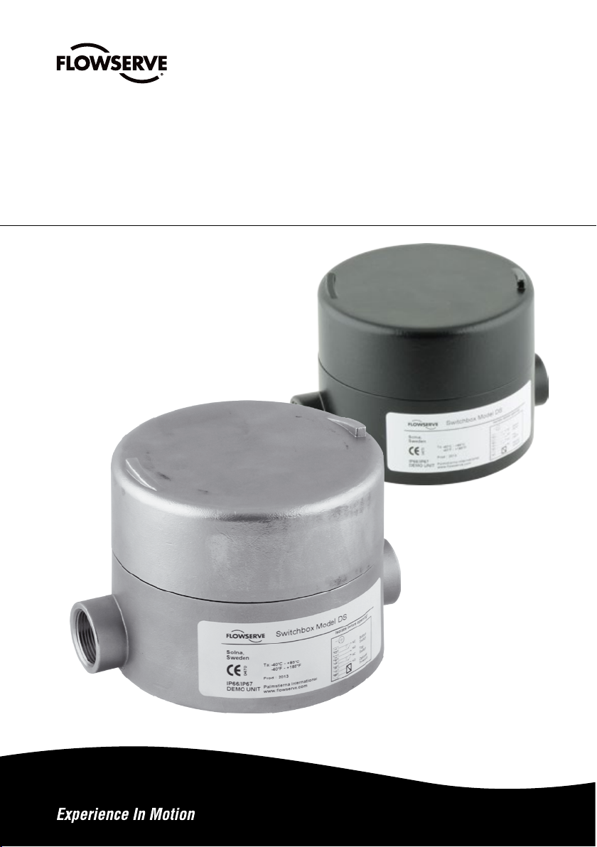
PMV DS/DM Ultraswitch™
Switch box
FCD PMENIM0020-00 - 02/15
Installation
Operation
Maintenance
Page 2

FCD PMENIM0020-00 - 02/15 FCD PMENIM0020-00 - 02/15
CONTENTS
1. GENERAL INFORMATION .........................................................................................................................3
2. SAFETY INSTRUCTION .............................................................................................................................3
3. UNPACKING ..............................................................................................................................................3
4. CERTIFICATES ..........................................................................................................................................4
5. SPECIFICATIONS ......................................................................................................................................4
5.1 Technical data.........................................................................................................................................4
5.2 Materials of construction ........................................................................................................................4
5.3 Product label ..........................................................................................................................................4
5.4 DS/DM UltraSwitch™ nomenclature ......................................................................................................5
5.5 DS/DM UltraSwitch™ switch options ......................................................................................................6
6. INSTALLATION .........................................................................................................................................7
6.1 Wiring instructions ..................................................................................................................................8
7. SWITCHES (Certified) ..............................................................................................................................9
7.1 Installation in hazardous locations ..........................................................................................................9
7.2 Adjusting limit switches ..........................................................................................................................9
7.3 Cam fine adjustment ............................................................................................................................10
7.4 Adjusting UltraDome™ position indicator ..............................................................................................10
7.5 Analog feedback option specifications...................................................................................................10
7.6 Calibrating 4-20mA Transmitter ............................................................................................................11
8. DIMENSIONS ..........................................................................................................................................12
9. NOTES ....................................................................................................................................................13
1. GENERAL INFORMATION
PMV DS/DM UltraSwitch™ limit switch enclosures provide local and remote position indication for automated
valves. An external visual indicator for intuitive local position determination is optional. The DS/DM UltraSwitch™
is available with a number of limit switch options for remote indication in a variety of electrical applications.
They may also be used as a junction box for direct installation of solenoid valves.
2. SAFETY INSTRUCTION
Read the safety instructions in this manual carefully before using the product. If any questions arise during
installation, contact supplier/sales office before continuing further.
3. UNPACKING
Report transport damage to the carrier immediately. In case of discrepancies - contact your nearest
FLOWSERVE location.
• Substitution of components may impair suitability
for Div. 2 locations.
• Inspect periodically for degradation. Replace parts
if degradation is found.
• Cleaning this housing by rubbing should be done
in a non-hazardous area.
• Potential electrostatic charging hazard. Clean
only with a damp cloth – danger of propagating
discharge.
• All grounding and bonding installation requirements must be addressed.
• Pay attention to personal protection, (clothing,
glasses, gloves) when performing installation or
service.
• Use only Flowserve original spare parts not to
invalidate certification.
• All installation, inspection and maintenance
of the equipment should be performed by
suitably trained personnel. In addition, for ATEX, all
installation, inspection, maintenance and repair
must be done by suitably trained personnel. For more
information refer to EN 60079-14:1997, EN 60079-
17, EN 60079-18, EN 60079-19.
• Do not disconnect equipment unless area is known
to be non-hazardous.
• To prevent ignition of ammable or combustible
atmospheres, disconnect power before servicing.
32
Page 3
FCD PMENIM0020-00 - 02/15 FCD PMENIM0020-00 - 02/15
4. CERTIFICATES
ATEX II 2 GD Ex d IIC T4 Gb, Ex tb IIIC T113°C Db IP66
All certificates available for
download at www.pmv.nu
IECEx Ex d IIC T4 Gb, Ex tb IIIC T113°C Db IP66
5. SPECIFICATIONS
5.1 Technical data
Enclosure ratings IP66, IEC 529
Weight Aluminum housing 1.8kg / 4 lbs
Weight Stainless Steel housing 3.5kg / 7.75 lbs
Working Temperature: -40°C to +85°C / -40°F to +185°F
Maximum Surface Temperature: +120°C / +248°F
5.2 Materials of construction
Housings & Covers Powder epoxy painted Aluminum or Stainless Steel
Shaft Stainless Steel
Cams/Splines Nylon
Terminal Block Nylon
Internal Brackets Nylon, Aluminum or Stainless Steel
All External Fasteners Stainless Steel
All Internal Fasteners Stainless Steel
Indicator Polycarbonate/Polyurethane
Label Polyester or Stainless Steel
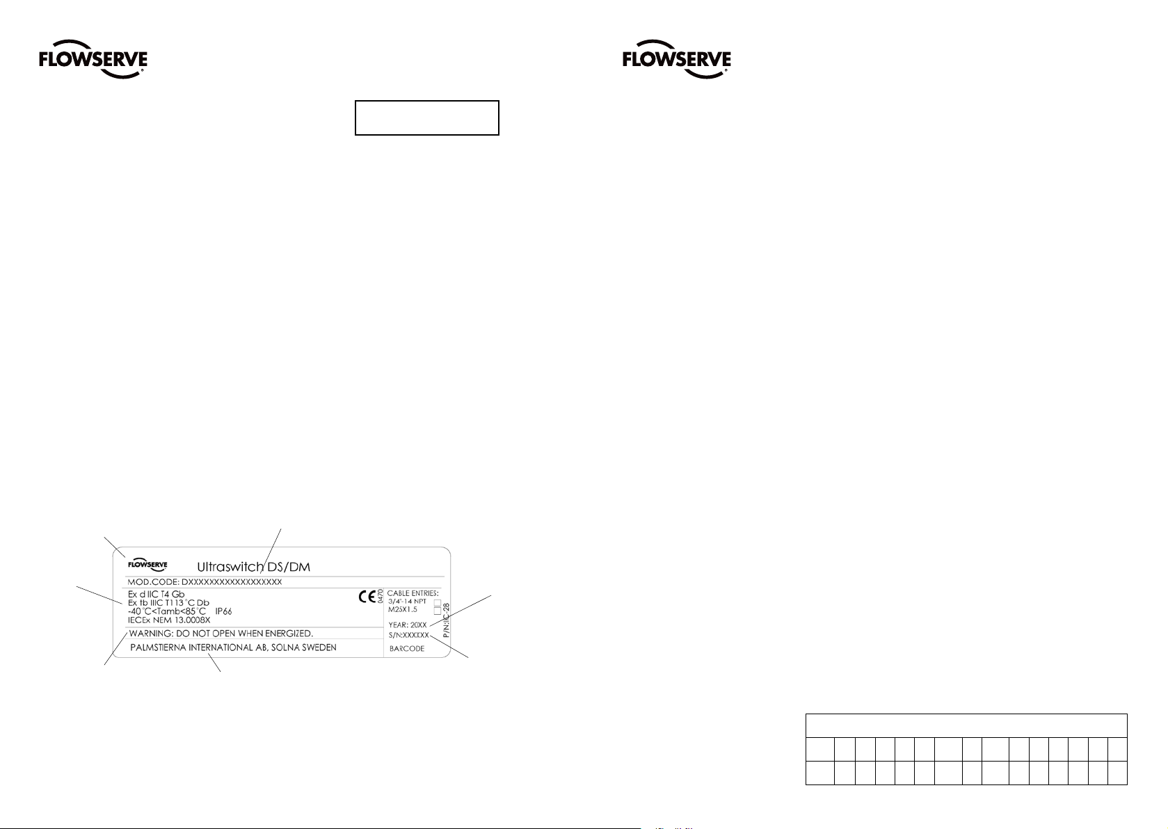
5.3 Product label
Logotype
Electrical
rating
Warnings
Manufacturer
Product name and model code
Serial number
Year of
manufacture
5.4 DS/DM UltraSwitch™ nomenclature
A = Product & Connections (cable entry)
DS Explosion proof / Flame proof switch box with 3/4” NPT cable entries
DM Explosion proof / Flame proof switch box with M25x1,5 cable entries
B = Number of open cable entries
2 2 x open cable entries (standard)
3 3 x open cable entries (option)
C = Housing material /Surface treatment
B Aluminum housing, polyester powdercoating, Black base & cover
W Aluminum housing, polyester powdercoating, Black base & White cover
C Aluminum housing, polyester powdercoating, Black base & Optional cover color
S Stainless Steel housing DIN 1.4408 - EN G-X 6 CrNiMo 18-10 - SAE 316
D = Shaft
D Double ’D’ Shaft 1/4”
N Namur VDI/VDE 3845 Shaft (rotary actuators)
T For NAF Turnex actuators
L D style including nut for linear applications
E = Indicator option
0 Flat top cover, no indicator
1 Flat top cover, indicator below switchbox for 90 deg
F = Qty of switches
0 0 switches (Cam assembly for 2 x M1 only)
2 2 Switches
4 4 Switches
G = Switch options - see page 6 for switch options
H = Certificate
14 General Purpose
19 ATEX II 2 GD Ex d IIC, IECEx Ex d IIC
I = Product approval marking
0 Self-adhesive marking label, Polyester
M Stainless steel marking plate
J = Analog Output
0 None
4 4-20mA transmitter (F=0 only)
K = Terminal Options
2 2 Extra open terminals (Standard)
4 4 Extra open terminals (Optional, not possible for all switch options)
6 6 Extra open terminals (Optional, not possible for all switch options)
8 8 Extra open terminals (Optional, not possible for all switch options)
H Heavy Duty Terminal Block, 8 contact points.
L = Options/ Elastomers
0 Nitrile O-rings
V Viton O-rings
M = Brand
P PMV
Ordering code example
A B C D E F G H I J K L M
DS 2 B N 1 2 MG - 14 - 0 0 2 0 P
54
Page 4

FCD PMENIM0020-00 - 02/15 FCD PMENIM0020-00 - 02/15
5.5 DS/DM UltraSwitch™ switch options
Code
Switch Option Manufacturer Part Number Load Capacity
F3 IFM IF5250 10-36VDC NC PNP, 150mA, 3-wire NC
F5 IFM IF6001 18-32VDC,NOPNP,150mA@50°C
F6 IFM IF6034 10-36VDC, NO PNP, 150mA, Stainless steel
F7 IFM IN0074 20-250 AC/DC, NO, 350mA/100mA
F8 IFM IN0081 20-250 AC/DC, NO, 350mA/100mA w/LED
F9 IFM IN0097 20-250V AC/DC NO 2-Wire (H=14 only)
FB IFM IF5249 10-36VDC NO PNP, 150mA, 3-wire NO
FC IFM IF5718 10-36VDC NO PNP/NPN, 150mA, plastic
FG IFM IS5070 10-36 VDC NO PNP 3-wire (H=14 only)
M1 SPDT Honeywell V7-1C13D8-201 15.1A (1/2 HP) at 125/250 AC;
Mechanical MicroSwitch A at 125 VDC; 1/4A at 250VDC; 5A at 120Vac
MG SPDT Honeywell V7-1D19D8-201 1A at 125 VAC / 50 mA at 24 VDC
Gold Mechanical MicroSwitch
N1 Pepperl+Fuchs NJ4-12GM40-E Proximity 3-wire NPN NO 10-60 VDC
N3 Pepperl+Fuchs SJ3,5-S1N NAMUR NO 8V
N8 Solid State Proximity Pepperl+Fuchs NJ2-V3-N NAMUR Sensor Output / 5-25 VDC Supply
N9 Solid State Proximity Pepperl+Fuchs NBB3-V3-Z4 NPN Sourcing/ 100 mA max. Current / 5-60 VDC
NA Pepperl+Fuchs NBN4-12GM40-E2 Inductive. 3 wires PNP NO 10-30VDC
ND Pepperl+Fuchs NCB2-12GM40-Z1 Proximity inductive 2-wire DC NC
NE Pepperl+Fuchs NCB2-12GM35-N0 NAMUR with LED NC 8,2V
NF Pepperl+Fuchs NCN4-12GM35-N0 NAMUR with LED NC 8,2V
NG Pepperl+Fuchs NJ5-11-N-G NAMUR NC 8,2V
NK Pepperl+Fuchs NCN4-12GM40-Z0 Proximity 2-wire DC NO 8,2V
NM Pepperl+Fuchs NJ2-11-SN-G NAMUR NC 5-25 VDC
NP Solid State Proximity Pepperl+Fuchs SJ3.5-N NAMUR 5-25 VDC Supply
NQ Solid State Proximity Pepperl+Fuchs NJ4-12GK-N NAMUR NC-Sensor, 8VDC
NR Solid State Proximity Pepperl+Fuchs NJ4-12GM40-E1 NPN Sinking / 200 mA max. Current / 10-60 VDC
NS Solid State Proximity Pepperl+Fuchs NJ4-12GM40-E2 PNP Sourcing / 200 mA max. Current / 10-60 VDC
NT Solid State Proximity Pepperl+Fuchs NJ4-12GK40-E2 NPN Sourcing / 200 mA max. Current / 10-60 VDC
NW Solid State Proximity Pepperl+Fuchs SJ3,5-SN NAMUR Sensor Output / 5-25 VDC Supply
P4 SPST Proximity Aleph PS-6132 0.35A at 140 VAC / .25A at 200VDC (50 W Max.)
P5 SPDT Proximity Hamlin 59135-030 0.25A at 120 VAC / 0.25A at 28 VDC (3 W Max.)
PE SPDT Sabre Proximity Flowserve XA0199 1A at 120 VAC / 2A at 24 VDC
PP SPDT Phazer Proximity Flowserve XA0155 3A at 120 VAC / 2A at 24 VDC
PT SPST BRS Proximity Flowserve XA0157 3A at 120 VAC / 0.5 at 24 VDC
6. Installation
A variety of mounting hardware is available for
mounting the DS/DM Ultraswitch™ to valve actuators.
For best results, specify the NAMUR shaft option and
NAMUR mounting hardware when installing to NAMUR
compliant actuator.
The NAMUR mounting hardware allow direct
coupling to actuators without adaptors, reducing dead
band. Simply bolt bracket to actuator and DS/DM
UltraSwitch™ to bracket, leaving bolts finger tight.
For NAMUR applications the DS/DM UltraSwitch™
shaft features an integral alignment pin. This pin must
engage the tapped hole in the actuator shaft.
For non-NAMUR applications, make sure to properly
install a coupler between DS/DM UltraSwitch™ and
actuator. Once the DS/DM UltraSwitch™ is installed
with fasteners loosely tightened, stroke the actuator
two or three times to align the bracket. Then tighten
all fasteners.
NOTE: External mounting fasteners must not be
allowed to bottom. Select length of screws to allow
at least one thread turn of clearance against bottom
of female thread when screw is tightened (due to
approval conditions). See picture.
NOTE: If the equipment is likely to come into
contact with aggressive substances, then it is the
responsibility of the user to take suitable precautions
that prevent it from being adversely affected, thus
ensuring that the type of protection provided by the
equipment is not compromised.
76
Page 5

FCD PMENIM0020-00 - 02/15 FCD PMENIM0020-00 - 02/15
6.1 Wiring instructions
DS/DM UltraSwitch™ enclosures feature prewired switches. All user connections are made at a
numbered terminal strip. Both external and internal
grounding locations have been provided for use in
installation (see illustration to the right). A wiring diagram is located inside the cover and indicates which
terminal numbers correspond to switch contacts:
normally open, normally closed, common, etc. Follow
the wiring diagram and electric code to connect the
switches to your system.
For field wiring: ensure that any excess wire lengths
or loops are routed away from any moving parts
and are short enough, or secured to ensure a ¼”
clearance between the wire and the inside surface of
the switchbox cover.
Solenoids may also be wired through the DS/DM
UltraSwitch™ enclosure. At least two auxiliary
terminals are included as standard. Wire the solenoid
to auxiliary terminals, then connect power leads to the
opposite terminal side. Be sure to properly ground the
solenoid at provided ground terminals.
DS/DM UltraSwitch™ DS-Series enclosures include
two 3⁄4” NPT conduit/cable entries and the DM-Series
include two M25x1.5 conduit/cable entries.
Ground terminals
7. Switches (certified)
Substitution of components may impair suitability for hazardous (classied) locations. Do not
disconnect equipment unless area is known to be non-hazardous.
To prevent ignition of ammable or combustible atmospheres, disconnect power before servicing.
7.1 Installation in hazardous locations
Installation of this device may only be performed by authorized personnel. All wiring and other external
components used to connect this device must comply with the hazardous locations regulations.
Special conditions for safe use
According to ATEX marking on the units indicates
WARNING: Do not open when energized. After de-energizing – delay 8 minutes before opening.
Seal within 50 mm of enclosure. Connecting cables must be rated for Tamb> 161°C / 322°F.
According to CSA marking on the units indicates
WARNING: To prevent ignition of hazardous atmospheres – disconnect before opening.
WARNING: Conduit runs must have seal fittings installed within 50 mm of the enclosure.”
7.2 Adjusting limit switches
UltraSwitch™ enclosures feature Quick-Set™ cams
which are used to trip the limit switches. These cams
are easily adjusted without tools.
Caution: Disconnect power before removing cover
when installed in hazardous locations.
Remove cover and set aside. Rotate actuator/valve to
full clockwise (CW) position. Adjust cam(s) associated
with CW as follows:
Caution!
• Proper and suitable conduit plugs must be installed
in unused conduit entries before placing the unit
into service.
• Install according to National Electric Code, local
codes, local certificates and manufacture instructions in all cases. Environmental seals must
be used to protect ingress of water through the
conduits. Electrical connections/plugs must
comply with relevant approval standards.
• Connecting cables must be rated for ambient
temperature above 161°C (322°F).
Note: The outside ground terminal of the Aluminum
housing has a stainless steel washer underneath
the grounding jumper. Make sure that the grounding
cable is squeezed between the washer and the
grounding jumper (see picture above).
1. Push or pull cam against spring to disengage it
from splines.
2. Rotate cam CW breaking contact with switch (or
moving magnet away from switch).
3. Continue rotating cam CW just until switch trips.
4. Release cam and re-engage it with splines.
Rotate actuator/valve to full counter-clockwise (CCW)
position. Adjust cam(s) associated with CCW as
described in steps 1 through 4, except rotate cam(s)
CCW.
Cam adjustment
Note: factory setting is:
Top switch = CW (closed)
Second switch = CCW (open)
Third switch = CW
Fourth switch = CCW
98
Page 6

FCD PMENIM0020-00 - 02/15 FCD PMENIM0020-00 - 02/15
7.3 Cam fine adjustment
Some cams have a fine adjustment available. These
cams will have a small screw embedded into the side
of the cam.
Adjusting this screw clockwise or counter clockwise
will deform the cam, changing the trip point slightly.
7.4 Adjusting Visual Position Indicator
(optional part):
As an option, the DS/DM UltraSwitch™ can be
equipped with a visual indicator located beneath the
housing. This ring-type indicator can easily be adjusted
using manual force. Simply rotate the indicator by hand
to the desired position. Double check that its position
corresponds to the position of the valve.
Mounting instructions are included in the box.
Cam fine adjustment
7.6 Calibrating 4-20 mA transmitter
Setting direct/reverse action: A dip-switch setting
controls the direction of increasing travel. For 4 mA in
the full clockwise position, select ”D”, for 4 mA in the
full counterclockwise position, select ”R”.
Adjusting zero/span:
1. Attach a DC mA meter to +/- terminals.
2. Operate valve/switch box to position corresponding
to 4 mA.
3. Adjust feedback board zero trim pot to yield 4
mA. (Turning CW increases value, turning CCW
decreases value).
- +
4. Operate valve/switch box to position corresponding
to 20 mA feedback.
5. Adjust feedback board span trim pot to yield 20
mA. (Turning CW increases value, turning CCW
decreases value).
6. The zero and span adjustments are interactive.
Repeat steps 1 through 5 as necessary.
Note: If transmitter adjustment gets difcult (i.e.,
trim pots do not have desired effect) start again by
”centering” the trim pots. This is accomplished by
turning in one direction for 20 turns and reversing
direction for 10 turns.
4-20 mA Transmitter
- +
mA meter
7.5 Analog feedback option specifications
Option 4 - 4-20 mA Transmitter
Voltage Supply: 6-30 VAC
Impedance: 300 Ohms at 20 mA
6-30 VDC
1110
Page 7

FCD PMENIM0020-00 - 02/15 FCD PMENIM0020-00 - 02/15
8. Dimensions (mm/Inch)
M6(4X)
Ø 125 (4.213)
35,4 (1.394)
57,2 (2.252)
3/4”-14 NPT OR
M25x1.5 (1-3x)
35,4 (1.394)
57,2 (2.252)
5/16”-18 UNC(4X)
93 (3.740)
99,3 (3.090)
Clearence=145 (5.701)
9. Notes
149 (5.866)
4 (.157)
137,5 (5.413)
DOUBLE “D” 1/4”
12,4
(.488)
NAMUR
VDI/VDE 3845
33
(1.299)
15(.590)
Ø56 (2.203)
SHAFTS
21(.827)
NAF TURNEX
20
(.787)
“D” WITH NUT
LINEAR
23
(.906)
1312
Page 8

FCD PMENIM0020-00 - 02/15 FCD PMENIM0020-00 - 02/15
9. Notes (continued)9. Notes (continued)
1514
Page 9

Country Name
Town Name, City 00000 Country
Telephone: 0 000 000 0000
Country Name
Town Name, City 00000 Country
Telephone: 0 000 000 0000
Country Name
Town Name, City 00000 Country
Telephone: 0 000 000 0000
Country Name
Town Name, City 00000 Country
Telephone: 0 000 000 0000
Country Name
Town Name, City 00000 Country
Telephone: 0 000 000 0000
Country Name
Town Name, City 00000 Country
Telephone: 0 000 000 0000
Country Name
Town Name, City 00000 Country
Telephone: 0 000 000 0000
Country Name
Town Name, City 00000 Country
Telephone: 0 000 000 0000
Country Name
Town Name, City 00000 Country
Telephone: 0 000 000 0000
Country Name
Town Name, City 00000 Country
Telephone: 0 000 000 0000
Country Name
Town Name, City 00000 Country
Telephone: 0 000 000 0000
Country Name
Town Name, City 00000 Country
Telephone: 0 000 000 0000
Country Name
Town Name, City 00000 Country
Telephone: 0 000 000 0000
To find your local Flowserve representative please use
the Sales Support Locator System found at
www.flowserve.com
Or call toll free: 0 000 000
To find your local Flowserve representative:
Bulletin XX-00-00 (X)
This area can be used for divisional information
Flowserve Corporation has established industry leadership in the design and manufacture of its products. When properly selected, this Flowserve
product is designed to perform its intended function safely during its useful life. However, the purchaser or user of Flowserve products should be aware
that Flowserve products might be used in numerous applications under a wide variety of industrial service conditions. Although Flowserve can provide
general guidelines, it cannot provide specific data and warnings for all possible applications. The purchaser/user must therefore assume the ultimate
responsibility for the proper sizing and selection, installation, operation, and maintenance of Flowserve products. The purchaser/user should read and
understand the (INSERT OFFICIAL USER INSTRUCTION TITLE) instructions included with the product, and train its employees and contractors in the
safe use of Flowserve products in connection with the specific application.
While the information and specifications contained in this literature are believed to be accurate, they are supplied for informative purposes only and
should not be considered certified or as a guarantee of satisfactory results by reliance thereon. Nothing contained herein is to be construed as a
warranty or guarantee, express or implied, regarding any matter with respect to this product. Because Flowserve is continually improving and upgrading
its product design, the specifications, dimensions and information contained herein are subject to change without notice. Should any question arise
concerning these provisions, the purchaser/user should contact Flowserve Corporation at any one of its worldwide operations or offices.
For more information about Flowserve Corporation, contact www.flowserve.com or call USA 1-800-225-6989.
To find your local Flowserve representative:
To find your local Flowserve representative please use the Sales Support
Locator System found at www.owserve.com
FCD PMENIM0020-00 - 02/15
Flowserve Corporation has established industry leadership in the design and manufacture of its
products. When properly selected, this Flowserve product is designed to perform its intended function
safely during its useful life. However, the purchaser or user of Flowserve products should be aware
that Flowserve products might be used in numerous applications under a wide variety of industrial
service conditions. Although Flowserve can provide general guidelines, it cannot provide specific
data and warnings for all possible applications. The purchaser/user must therefore assume the
ultimate responsibility for the proper sizing and selection, installation, operation, and maintenance
of Flowserve products. The purchaser/user should read and understand the (DS/DM Switch box User
Instructions) instructions included with the product, and train its employees and contractors in the
safe use of Flowserve products in connection with the specific application.
While the information and specifications contained in this literature are believed to be accurate, they
are supplied for informative purposes only and should not be considered certified or as a guarantee
of satisfactory results by reliance thereon. Nothing contained herein is to be construed as a warranty or guarantee, express or implied, regarding any matter with respect to this product. Because
Flowserve is continually improving and upgrading its product design, the specifications, dimensions
and information contained herein are subject to change without notice. Should any question arise
concerning these provisions, the purchaser/user should contact Flowserve Corporation at any one
of its worldwide operations or offices.
For more information about Flowser ve Corporation, contact www.owserve.com or call USA
1-800-225-6989.
© February 2015, Flowserve Corporation, Irving, Texas
Palmstierna International AB
Korta Gatan 9
SE-171 54 Solna
SWEDEN
Tel: +46 (0) 8 555 106 00
Fax: +46 (0) 8 555 106 01
E-mail: infopmv@owserve.com
Germany
Flowserve
Sperberweg 16
D-41468 Neuss
GERMANY
Tel: +49 (0) 2131 795 74 80
Fax: +49 (0) 2131 795 74 99
E-mail: pmvgermany@owserve.com
Flowserve Flow Control GmbH
Rudolf-Plank Strasse 2
D-76275 Ettlingen
GERMANY
Tel: +49 (0) 7243 103 0
Fax: +49 (0) 7243 103 222
E-mail: argus@owserve.com
UK
Flowserve
Abex Road
Newbury, Berkshire, RG14 5EY
UK
Tel: +44 (0) 1635 46 999
Fax: +44 (0) 1635 36 034
E-mail: pmvukinfo@owserve.com
Italy
Flowserve Spa
Via Prealpi, 30
20032 Cormano (Milano)
ITALY
Tel: +39 (0) 2 663 251
Fax: +39 (0) 2 615 18 63
E-mail: infoitaly@owserve.com
USA, Mexico
PMV-USA
14219 Westfair West Drive
Houston, TX 77041, USA
Tel: +1 281 671 9209
Fax: +1 281 671 9268
E-mail: salespmv@owserve.com
Asia Pacific Headquarters
Flowserve Pte Ltd.
No. 12 Tuas Avenue 20
REPUBLIC OF SINGAPORE 638824
Tel: +65 (0) 687 98900
Fax: +65 (0) 686 24940
E-mail: fcdasiaprocess@owserve.com
The Netherlands
Flowserve Flow Control Benelux
Rechtzaad 17
4703 RC Roosendaal
THE NETHERLANDS
Tel: +31 (0) 30 6771946
Fax: +27 (0) 30 6772471
E-mail: fcbinfo@owserve.com
flowserve.com
 Loading...