

Page 1
User Instructions ARG Series Standard Actuator - ACENIM0123-00 12/12
®
ARG Series Standard Actuator
Jackscrew Override
USER INSTRUCTIONS
Sandwich Gearbox Override
Hydraulic Override
FCD ACENIM0123-00 12/12
Installation
Operation
Maintenance
Experience In Motion
Worchester Controls
1
Page 2
User Instructions ARG Series Standard Actuator - ACENIM0123-00 12/12
STOP!
®
INDEX
1 Using Flowserve valves, actuators and acces-
sories correctly
2 Jackscrew Override
2.2 Install jackscrew override onto heavy duty DA
actuator
2.3 install jackscrew override onto existing heavy
duty SR actuator
2.4 Operation –Jackscrew Override
2.5 Automatic Operation
3 Gear Override
3.2 Retrofit Gear Override onto Existing ARG Actuator Installation
3.3 Mount a Preassembled Actuator
3.4 Operation
3.5 Restoring Automatic Operation
4 Hydraulic Override
4.2 Install hydraulic override onto existing heavy
duty Spring Return actuator
4.3 Operation –SR Override
4.4 Install hydraulic override on Standard DA
heavy duty actuator
4.5 Operation –DA Override
1 Using Flowserve Valves, Actuators and Acces-
sories Correctly
1.1 General usage
The following instructions are designed to assist in
unpacking, installing and performing maintenance
as required on FLOWSERVE products. Product users and maintenance personnel should thoroughly
review this bulletin prior to installing, operating or
performing any maintenance.
In most cases FLOWSERVE valves, actuators and
accessories are designed for specific applications
with regard to medium, pressure and temperature.
For this reason they should not be used in other applications without first contacting the manufacturer.
1.2 Terms concerning safety
The safety terms DANGER, WARNING, CAUTION
and NOTE are used in these instructions to highlight
particular dangers and/or to provide additional information on aspects that may not be readily apparent.
DANGER: indicates that death, severe personal injury
and/or substantial property damage will occur if proper
precautions are not taken.
WARNING: indicates that death, severe personal
injury and/or substantial property damage can occur
if proper precautions are not taken.
CAUTION: indicates that minor personal injury and/
or property damage can occur if proper precautions
are not taken.
NOTE: indicates and provides additional technical
information, which may not be very obvious even to
qualified personnel.
Compliance with other, not particularly emphasised
notes, with regard to transport, assembly, operation
and maintenance and with regard to technical documentation (e.g. in the operating instruction, product
documentation or on the product itself) is essential,
in order to avoid faults, which in themselves might
directly or indirectly cause severe personal injury or
property damage.
1.3 Protective clothing
FLOWSERVE products are often used in problematic
applications (e.g. extremely high pressures, dangerous, toxic or corrosive mediums). In particular valves
with bellows seals point to such applications. When
performing service, inspection or repair operations
always ensure, that the valve and actuator are depressurised and that the valve has been cleaned and is free
from harmful substances. In such cases pay particular
attention to personal protection (protective clothing,
gloves, glasses etc.).
1.4 Qualified personnel
Qualified personnel are people who, on account of their
training, experience and instruction and their knowledge of relevant standards, specifications, accident
prevention regulations and operating conditions, have
been authorised by those responsible for the safety of
the plant to perform the necessary work and who can
recognise and avoid possible dangers.
2
Page 3

User Instructions ARG Series Standard Actuator - ACENIM0123-00 12/12
STOP!
®
1.5 Installation
DANGER: Before installation check the order-no.,
serial-no. and/or the tag-no. to ensure that the valve/
actuator is correct for the intended application.
Do not insulate extensions that are provided for hot
or cold services.
Pipelines must be correctly aligned to ensure that the
valve is not fitted under tension.
Fire protection must be provided by the user.
1.6 Spare parts
Use on l y FLOWS E R V E origin a l spare parts.
FLOWSERVE cannot accept responsibility for any
damages that occur from using spare parts or fastening materials from other manufactures. If FLOWSERVE
products (especially sealing materials) have been on
store for longer periods check these for corrosion or
deterioration before using these products. Fire protection for FLOWSERVE products must be provided by
the end user.
1.7 Service / repair
To avoid possible injury to personnel or damage to
products, safety terms must be strictly adhered to.
Modifying this product, substituting nonfactory parts,
or using maintenance procedures other than outlined
in this instruction could drastically affect performance
and be hazardous to personnel and equipment, and
may void existing warranties. Between actuator
and valve there are moving parts. To avoid injury
FLOWSERVE provides pinch-point-protection in the
form of cover plates, especially where side-mounted
positioners are fitted. If these plates are removed
for inspection, service or repair special attention is
required. After completing work the cover plates must
be refitted.
1.8 Storage
In most cases FLOWSERVE products are manufactured
from stainless steel. Products not manufactured from
stainless steel are provided with an epoxy resin
coating. This means that FLOWSERVE products
are well protected from corrosion. Nevertheless
FLOWSERVE products must be stored adequately
in a clean, dry environment. Plastic caps are fitted
to protect the flange faces to prevent the ingress of
foreign materials. These caps should not be removed
until the valve is actually mounted into the system.
1.9 Valve and actuator variations
These instructions cannot claim to cover all details of
all possible product variations, nor can they provide
information for every possible example of installation,
operation or maintenance. This means that the
instructions normally include only the directions to
be followed by qualified personal where the product
is being used for is defined purpose. If there are any
uncertainties in this respect particularly in the event
of missing product-related information, clarification
must be obtained via the appropriate FLOWSERVE
sales office.
1.10 Unpacking
Each delivery includes a packing slip. When unpacking,
check all delivered valves and accessories using this
packing slip.
Report transport damage to the carrier immediately.
In case of discrepancies, contact your nearest
FLOWSERVE location.
Apart from the operating instructions and the
obligatory accident prevention directives valid in the
country of use, all recognised regulations for safety
and good engineering practices must be followed.
WARNING: Before produ c ts ar e re t urned to
FLOWSERVE for repair or service FLOWSERVE must
be provided with a certificate which confirms that
the product has been decontaminated and is clean.
FLOWSERVE will not accept deliveries if a certificate
has not been provided (a form can be obtained from
FLOWSERVE).
3
Page 4
User Instructions ARG Series Standard Actuator - ACENIM0123-00 12/12
®
2 Heavy Duty Jackscrew Overrides
Jackscrew overrides on Worchester Controls heavy duty actuators provide economical, durable method for manually
operating the actuator. The jackscrews are either direct operating or bevel gearbox driven, to reduce operation effort. The
direct operation consists of a rotating screw, threading into
the nut which is fitted on the Torque module/ Spring module,
and the hand wheel directly turns the screw.
The bevel gearbox driven jackscrew, has an arrangement of
rotating nut and a rising screw. The higher thrust requirements for models bigger than 4000 Nm and for the stiffer
springs are met with this type of jackscrew design.
Jackscrews are available on models ARG1 through ARG5.
2.1 Installation
worchester Controls standard jackscrew overrides are provided as a complete integral component of the heavy duty
actuator. Override units are shipped with the jackscrew assembly mounted to the actuator and vent valves installed on
the pressure module. No additional customer installation is
required. Refer Worchester Controls Heavy Duty IOM (FCD
AXENIM0121) for instructions on installing Heavy Duty actuator into service.
end flange, locating the spigot in the Torque module.
2.2.4 Use the jackscrew mounting kit and the O-ring from
the DA cover.
2.2.5 Tighten the mounting stud nuts fully, with lock washers from the kit.
2.2.6 Fix the 3 way vent valves supplied in the kit, to both
ports of the pressure module and connect air supply
pressure lines to these valves.
2.2.7 Installation of pressure module side jackscrew requires replacement of std end plate of the pressure
module. Remove tie rod nuts and end plate, and fit in
the jackscrew assembly, supplied preassembled with
the suitable thrust base End Plate. Tighten the tie rod
nuts back on the pressure module. Fix the 3way valve
on the ports.
2.3 Install jackscrew override onto existing heavy
duty SR actuator (see Fig.: 2)
2.3.1 Disconnect air pressure and electrical power from actuator.
2.2 Install jackscrew override onto heavy duty DA
actuator (see Fig.: 1)
2.2.1 Disconnect air pressure and electrical power from actuator.
2.2.2 Remove the DA end cover plate.
2.2.3 Back off the jackscrew fully in the assembly and
mount the jackscrew assembly on the torque module
2.3.2 Remove the end cover plate on the Spring module, retaining the cover O-ring.
2.3.3 Tighten the mounting studs from the mounting kit with
thread lock compound into the spring module end
plate.
2.3.4 Back off the jackscrew fully in the assembly and mount
the jackscrew assembly on the spring module end
plate’s thrust base, locating the spigot in the spring
4
Fig.: 1 Install Jackscrew Override (DA)
Page 5

User Instructions ARG Series Standard Actuator - ACENIM0123-00 12/12
®
Fig.: 2 Install Jackscrew Override (SR)
module end plate.
2.3.5 Locate the jackscrew nut or the spool (for bevel gearbox jackscrews) into the studs and tighten the nuts
fully, with lock washers from the kit.
2.3.6 Fix a 3 way valve, to the pressure module’s rod end
side port and connect air supply pressure line to it, see
fig.
2.4 Operation –Jackscrew Override
2.4.1 To test / operate the override, turn the 3 way valves to
shut off air supply and vent the cylinder ports.
sure module would be required for this.
2.5 Automatic Operation
2.5.1 Operate hand wheel counterclockwise to completely
retract the jackscrews and lock the position with the
locknut on the jackscrew.
2.5.2 Turn the 3way valves on the pressure module to connect to air supply.
2.5.3 Operate actuator normally on supply pressure.
2.4.2 Turning the hand wheel clockwise advances the screw
into the torque / spring module for DA/SR models.
2.4.3 Resistance will be felt when the thrust head of the
jackscrew touches the guide block face in case of DA
actuator or on the Pull Rod hex end, in case of the SR
model.
2.4.4 Tightening the hand wheel further clockwise will cause
the guide block to move against the resistance from
the valve/ spring and effect the override function.
NOTE: In case of SR jackscrew, the spring constantly
loads the screw, and returns the actuator to fail safe
state when the jackscrew is retracted. But in case of
DA models, the jackscrew on torque module retracts
free of load and does not move the actuator in the
other direction. An additional jackscrew on the pres-
5
Page 6

User Instructions ARG Series Standard Actuator - ACENIM0123-00 12/12
®
3 Heavy Duty Gear Overrides
Gear overrides on Worchester Controls ARG series heavy duty
actuators are available for models ARG1 through ARG5 providing a convenient and safe method for manually operating the
actuator, in event of supply failure. These are declutchable for
efficient, automatic operation. The gear override consists of a
declutchable gearbox mounted below the actuator, and is positioned between the ARG series actuator and the valve/damper to
be actuated.
Any accessories, such as limit switches and positioners, are not
disturbed and continue to be mounted on the NAMUR mounting
drive, on top side of the actuator.
The gear override is designed for the full rated torque of the
actuator and has an identical ISO base and bolting patterned, as
the actuator.
NOTE: In the event that needs the actuator to be removed
from the valve for maintenance or repair, the gearbox
can be left mounted on the valve, to allow manual operation.
3.1 Installation
bore of the actuator, aligning the keys on the shaft to the
keyways in the Yoke bore. Declutch the manual gearbox
(see instructions on gear box to disengage lock pin and
disengage the worm shaft).
3.2.6 Seat the actuator fully on the override gearbox flange and
thread in the Nuts with Lock washers from the Mounting
Kit, from below the mounting flange. Torque the Nuts to
rated torque for the Nut size.
3.2.7 Now this assembly is mounted on the valve stem or on
the bracket and coupler shaft, the way the actuator was
seated.
3.2.8 Bolt up the Gear drive mounting with the fasteners removed from the actuator-valve mounting.
3.2.9 Fit the 3 way valves to pressure module, per schematic
(see Figs. on page 5).
NOTE: After mounting actuator to valve, the gear over-
ride travel stops must be set. First make sure that the
actuator travel stops are set correctly. Then set the
gear override travel stops to the same position.
Worchester Controls standard sandwich gear overrides are provided as a modular component of the heavy duty actuator. Gear
override units are shipped with the gear mounted to the actuator. The vent valves are installed on the pressure cylinder. No
additional customer installation is required. Refer Worchester
Controls Heavy Duty ARG series IOM (FCD ACENIM0121) for
instructions on installing Heavy Duty actuator into service.
3.2 Retrofit gear override onto existing ARG actuator installation
3.2.1 Disconnect air pressure and electrical power from actuator and dismount the actuator from valve/mounting
bracket.
3.2.2 Thread in fully, the studs from the Gear Override Mounting Kit, into the mounting base of the removed actuator.
3.2.3 Orient the manual override gear to the fail safe position
of the actuator, if actuator is spring return model, or else
bring both the actuator and the gear to the same position, say Clockwise end. Back off the gearbox’s travel
stops.
3.2.4 The coupler shaft is fitted into and supplied with the
gearbox. The coupler shaft bottoms out on the step/
circlip inside the gear bore, preventing it from sliding
through the gear bore.
3.2.5 Mount the actuator on to the coupler shaft, into the yoke
3.3 Mount a preassembled actuator- gear override
assembly on the valve, a mounting bracket and
a Coupler/ Adaptor shaft is required with the
mounting kit.
3.3.1 Fix the mounting bracket on to the valve with the fasteners from the mounting kit.
3.3.2 Locate the Coupler/Adaptor shaft supplied, on the valve
stem and lock to the stem.
3.3.3 Orient the actuator and the valve to same position, usually the fail safe condition of the actuator for SR/SO models and full clockwise end, for DA models.
3.3.4 Disengage the worm shaft from the worm wheel of the
override gearbox (see declutching instructions on the
override gearbox).Back off the override gearbox’s travel
stops.
3.3.5 Now mount the actuator-override gearbox assembly on
the coupler shaft, aligning the keys into the keyways in
the gear bore. Seat the actuator assembly on the bracket
and fasten with the mounting bolts.
3.3.6 Set the Actuator’s travel stops to the position required by
the valve.
3.3.7 Set the override gearbox’s travel stops to the same position as the actuator, and lock the setting.
6
Page 7

User Instructions ARG Series Standard Actuator - ACENIM0123-00 12/12
®
7
Page 8

User Instructions ARG Series Standard Actuator - ACENIM0123-00 12/12
®
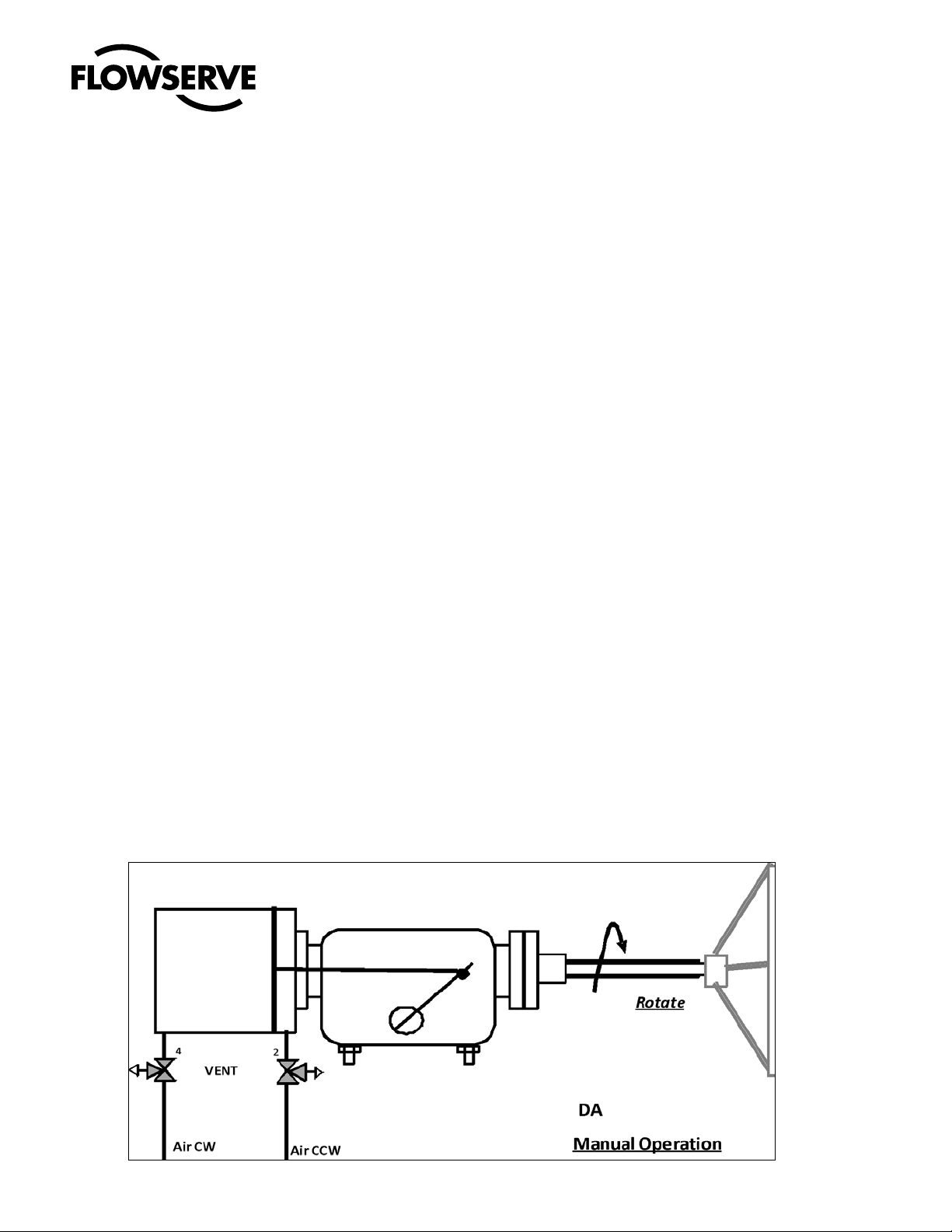
3.4 Operation
Manual Operation (In the absence of pneumatic pressure
only)
3.4.1 Turn the 3 way valves on the pressure module to vent the
cylinder ports to atmosphere. Ensure all vent valves are
in vent position. Number of these valves varies as per the
actuator type (DA/DD/SR).
3.4.2 Rotate the hand wheel on the manual override until the
position indicator on the manual override agrees with the
valve position.
4 Hydraulic Override
Hydraulic overrides on Worchester Controls heavy duty actuators provides a low effort, high thrust in compact sized
override, for manually operating the actuator. The hydraulic
overrides are single acting on the SR models and double
acting on the DA actuator for efficient, automatic operation.
These are available on models ARG3 through ARG8.
The hydraulic override consists of a power pack with hand
operated high pressure pump connected by SS tubing, to hydraulic cylinder, mounted on spring module on SR models
and on the torque module, on the DA models.
NOTE: The position indicator on the manual override
indicates actuator/valve position only when the hand
wheel is engaged. (Position indicator shows ‘SHUT’ in
full CW position and ‘OPEN’ in full CCW position)
3.4.3 Engage worm shaft by pulling out the lock pin and rotate the engage-disengage lever 90 degrees till the spring
loaded lock pin drops into the indexed position. Operate
hand wheel to turn the gear override. Follow instructions
on gearbox to engage the worm shaft.
3.4.4 Manually operate the actuator by turning the hand wheel.
See direction markings on the gearbox and turn the hand
wheel accordingly to open/shut the valve.
3.5 Restoring Automatic Operation
3.5.1 Operate hand wheel to desired valve position. This should
be fail safe position, for a spring return actuator.
3.5.2 Pull out the lock pin of the declutch mechanism, out of
locking position, and turn the lever to Disengage the
worm shaft from the wheel. Turn the lever until the lock
pin sits into the indexed position. It may be necessary to
rotate the hand wheel back & forth at the same time the
declutching handle is lifted, to relieve the load on the
declutching pin.
3.5.3 Turn the 3 way valves, on the pressure module ports to
connect cylinder ports to air supply pressure.
The hydraulic override provides adequate thrust to output the
rated torque on DA models, and required valve torque output
for the operation of SR models.
4.1 Installation
Worchester Controls standard hydraulic overrides are provided as a complete integral component of the heavy duty actuator. Hydraulic override is shipped with the cylinders mounted
to the actuator and bypass/vent valves installed on the pressure cylinders. The power pack is selected, factory fitted and
connected, as per the application. No additional customer
installation is required. See Worchester Controls Heavy Duty
IOM (FCD WCENIM0121) for instructions on installing Heavy
Duty actuator into service.
4.2 Install hydraulic override onto existing heavy
duty Spring Return actuator (see Fig.: 2)
4.2.1 Disconnect air pressure and electrical power from actuator.
4.2.2 Remove the end cover plate, retaining the O-ring on
the Spring Module end.
4.2.3 Thread in the studs (1), from the override mounting
kit, into the thrust base and insert the Hydraulic Cylinder into the Spring Module to mate the cylinder flange
inner face to the thrust base, keeping the air venting
plug to the top (see Fig.: 1 ).
3.5.4 Operate actuator normally with pneumatic pressure supply.
CAUTION! The gearbox override on a spring return ac-
tuator shall not be disengaged while the spring is under compression. Engagement and disengagement of
the worm shaft of the override gearbox should be done
only at the Fail Safe condition of the actuator.
8
Fig.: 1 Insert Hydraulic Cylinder
Page 9

User Instructions ARG Series Standard Actuator - ACENIM0123-00 12/12
®
Hydraulic Pressure Settings for SR Models, psi
Model
ARG3
ARG4
ARG5
ARG6
ARG7
ARG8
1 2 3 4 5 6 7 8
1550 2000 2400 2850 3000 3000 3000
1350 1580 1950 2200 2450 2900 3000 3000
1200 1680 2000 2300 2900 3000
1000 1550 1900 2200 2500 2800
1050 1750 2000 2350 2800 3000
1150 1800 2300 2700 2900 3000
Hydraulic MOP: 3000 psi
Fig.: 2 Install Hydraulic Override (SR)
4.2.4 Bolt up the cylinder flange on the thrust base of the
Spring Module using the using the lock washers and
nuts from override mounting kit.
4.2.5 Thread in the hydraulic connector into the cylinder port
and connect it to the power pack, as per the schematic.
4.2.6 Fit the 3 way valves supplied in the mounting kit, to the
pressure module’s ports, as per the schematic.
Spring Module
4.3 Operation –SR Override
4.3.1
To operate the override, turn the 3/2 way valve on pressure module to vent the cylinder port to atmosphere and
Close the pressure release valve, PRV (provided either
externally or integral with the hand pump). Operating the
Hand Pump on the power pack pushes the pull rod, compresses the spring and operates the valve.
4.2.7 Fill to level, hydraulic fluid (ISO 32 grade for general
application) in the power pack reservoir, in the full retracted position of the piston.
4.3.2
Opening the pressure release valve, PRV releases the hydraulic pressure and the spring returns the actuator to fail
safe state and the piston rod of override cylinder to retracted
position.
4.2.8 Verify the maximum hydraulic pressure setting for the
actuator model (refer table), close the pressure release
valve on the pump and operate the hydraulic pump to
start the ram movement. Lightly loosen the air vent
4.3.3 To restore normal Automatic operation, turn the PRV
to Open and switch the 3/2 way valve in position to
connect cylinder port to air supply pressure.
screw on the cylinder flange to bleed off air from the
hydraulic lines. The ram touches the Pull Rod’s end
face and pushes the pull rod, effecting the override.
4.2.9 Adjust the overload valve setting on the pump to ensure the pressure does not grossly exceed the Hydraulic pressure setting for the actuator, at the end of the
stroke when the stopper bolt gets loaded.
Piston rod/pull Rod Torque
Hex Size, A/F 18 18 24 30 36 46 65 85
Tightning
torque
ft Lb 30-35 35-45 50-60 60-75 75-85 100-140 175-200 200-240
kgm 4-5 4-5 7-8 8-10 10-12 13-19 24-28 28-33
4.4 Install hydraulic override on Standard DA heavy
duty actuator
4.4.1 Remove the DA cover plate from the torque module
and mount the DA hydraulic override cylinder assembly with the mounting kit and flange O-ring in the face
groove.
9
Page 10
User Instructions ARG Series Standard Actuator - ACENIM0123-00 12/12
®
4.4.2
Remove end cap of the hydraulic cylinder. With a suitable socket/tube spanner located on the hex head of the
hydraulic piston end, thread in and tighten the piston rod
into the threading of the Torque Module’s Guide Block.
Torque
to values, as for pull rod/ piston rod.
4.4.3 Put back the end cap, taking care not to damage the
cap seal, and tighten fully the tie rod nuts of the hydraulic cylinder.
4.4.4 Connect the ports of the hydraulic cylinder to the direction control valve on the hydraulic power pack. Refer schematic.
4.4.5 Check and ensure the Hydraulic pressure setting of
the pump does not exceed the MOP setting, refer table
below. Use the plugged port on the pressure line Tee,
to connect a suitable pressure gage.
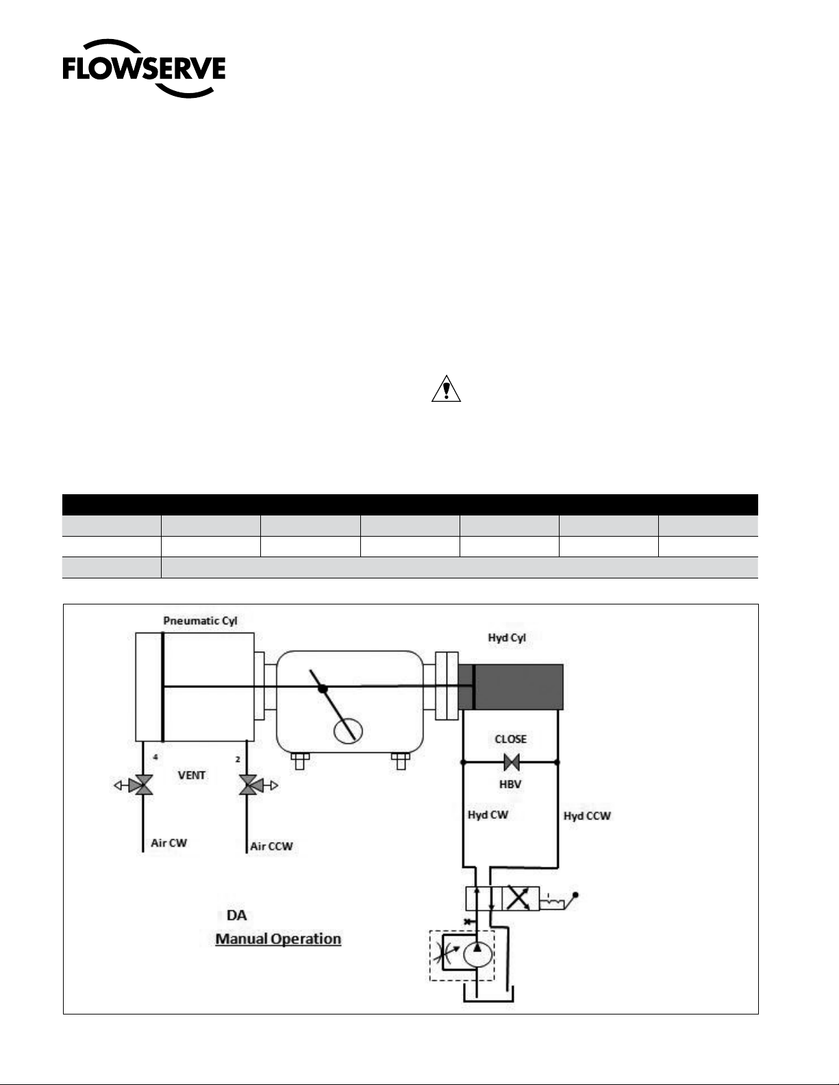
4.5 Operation –DA Override
4.5.1 For Manual Override operation, turn the 3 way valves
on the pressure module to vent cylinder ports to atmosphere and Close the the hydraulic bypass valve,
HBV (if provided externally). Close the pressure release valve on the pump. Turn the lever on the 4 way
direction control valve on the power pack, to select
the direction of the actuator rotation and stroke the
hydraulic pump.
4.5.2 To restore Automatic operation, turn HBV to Open
position, turn the vent valves to connect the cylinder
ports to air supply pressure and open the pressure
release valve on the hand pump.
CAUTION! Over thrust by the hydraulic override may
cause actuator damage. Prevent damage and unsafe working, by adjusting the overload valve on the
pump to limit the hydraulic pressure, as shown in
the table.
Model
MOP, psi
Max. System Pr
DA Hydraulic Override Pressure for Rated Body torque
ARG3 ARG4 ARG5 ARG6 ARG7 ARG8
1860 2100 2050 1950 1950 2150
2500 psi
Fig.: 3 Install Hydraulic Override (DA)
10
Page 11

User Instructions ARG Series Standard Actuator - ACENIM0123-00 12/12
®
11
Page 12

Contact:
User Instructions ARG Series Standard Actuator - ACENIM0123-00 12/12
®
All data subject to change without notice
© ©12.2010 Flowserve Corporation. Flowserve and Kämmer are trademarks of Flowserve Corporation
Flowserve Corporation has established industry leadership in the design and manufacture of its products. When properly selected this Flowserve product is designed to perform its intended function safely during its useful life. However, the purchaser
or user of Flowserve products should be aware that Flowserve products might be used in numerous applications under a wide variety of industrial service conditions. Although Flowserve can (and often does) provide general guidelines, it cannot
provide specific data and warnings for all possible applications. The purchaser/user must therefore assume the ultimate responsibility for the proper sizing and selection, installation, operation, and maintenance of Flowserve products. The purchaser/
user should read and understand the Installation Operation Maintenance (IOM) instructions included with the product, and train its employees and contractors in the safe use of Flowserve products in connection with the specific application.
While the information and specifications contained in this literature are believed to be accurate they are supplied for informative purposes only and should not be considered certified or as a guarantee of satisfactory results by reliance thereon.
Nothing contained herein is to be construed as a warranty or guarantee, expressed or implied, regarding any matter with respect to this product. Because Flowserve is continually improving and upgrading its product design, the specifications,
dimensions and information contained herein are subject to change without notice. Should any question arise concerning these provisions, the purchaser/user should contact Flowserve Corporation at any one of its worldwide operations or offices.
Flowserve Flow Control (UK) Ltd.
Burrell Road
Haywards Heath
West Sussex United Kingdom RH16 1TL
Phone:
+44 1444 314400
Fax:
+44 1444 314401
Flowserve Corporation
Flow Control Division
1978 Foreman Drive
Cookeville, Tennessee 38501 USA
Phone: +931 432 4021
Fax: +931 432 5518
12
Flowserve Pte Ltd
No. 12 Tuas Avenue 20
Singapore 638824
Phone: +65 6879 8900
Fax: +65 6862 4940
Flowserve Flow Control Benelux BV
Rechtzaad 17
4703 RC Roosendaal NB
Netherlands
Phone: +31 165 598 800
Fax: +31 165 555 670
Flowserve Australia Pty Ltd
Flow Control Division
14 Dalmore Drive
Scoresby, Victoria 3179
Austrialia
Phone: +61 3 9759 3300
Fax: +61 3 9759 3301
Flowserve do Brasil Ltda
Rua Tocantins, 128 - Bairro Nova Gerti
São Caetano do Sul,
São Paulo 09580-130 Brazil
Phone: +5511 4231 6300
Fax: +5511 4231 6329 - 423
Unit 01\02\06\07 9F
China Fortune Tower
No. 1568, Century Avenue, Pudong
Shanghai China 200122
Phone: +86 21 38654800
Fax: +86 21 50811781
Flowserve Corporation
No. 35, Baiyu Road
Suzhou Industrial Park
Suzhou 215021, Jiangsu Province, PRC
Phone: +86-512-6288-1688
Fax: +86-512-6288-8737
 Loading...