

Page 1

3-Position Control/Dribble Control
CONTROLS
Accord Controls 765 South 100 East Phone: 801 373 4576
A Unit of Flowserve Corporation Provo, Utah 84606 Facsimile: 801 489 2591
Installation, Operation and Maintenance Instructions
SR Limit Switch Method
AR5 Actuator
www.accord-controls.com
AR5 Actuator
AR5 Scotch-Yoke Actuator
The AR5 scotch-yoke actuator is an extension to the ARseries pneumatic scotch-yoke actuator. The AR5 actuator will
produce up to 500,000 in.-lb. double acting torque and
225,000 in.-lb. spring end torque.
Installation to Valve
1. All actuators are factory lubricated for life, but still
should be protected from the elements and stored
indoors until ready for use. The ports of the actuator
are plugged as supplied from the factory. If actuators
are stored for a long period of time prior to installation,
the actuators should be stroked every 3 months to
prevent the seals from taking set. See bulletin B00129
for long term storage instructions.
2. Prior to assembly, manually open and close valve to
ensure freeness of operation. Be sure valve and
actuator rotate in the same direction and are in the
same position (i.e. valve closed, actuator closed).
3. Check the mounting surfaces, the stem adaptor, and
the bracket to assure proper fit. Secure the valve in the
closed position with the stem vertical. Bolt the bracket
to the valve and place the stem adaptor on the valve
stem. Position the actuator over the valve and lower to
engage the stem adaptor to the actuator output bore.
Continue to lower until the actuator seats on the
bracket mounting surface. In order to align the bolt
holes, it may be necessary to turn or stroke the
actuator a few degrees and/or adjust the actuator
travel stops. Bolt the actutor to the bracket.
4. Adjust the travel stop bolts of the actuator for the
proper open and closed valve positions, per valve
manufacturer’s recommendations. Pneumatically
stroke the actuator several times to assure proper
operation. The stem adaptor should not bind during
operation. If the actuator is equipped with an
UltraSwitch or other accessories, adjust them at
this time.
5. To prolong actuator life use only clean, dry plant air.
Lubricated air is not required, however it is recommended
particularly for high cycleapplications.
Caution: Do not use Lubricated air with Positioners.
Travel Stop Adjustments
All actuated valves require accurate travel-stop adjustments at
both ends of the stroke to obtain optimum performance and
valve seat life. The accumulation of tolerances in the adaption
of actuators to valves is such that there must be a range of
adjustments for both ends of the stroke to achieve optimum
performance.
The AR5 actuator has travel stop adjustments in both the
clock-wise and counter-clockwise directions. The 12 degree
over-travel feature provides adjustments from -6 to +96
degrees.
Field Conversion from Fail CW to Fail CCW
(for Spring Return Actuators)
The AR5 spring return actuator can be converted from fail CW
to fail CCW easily. Simply turn actuator over and mount to
valve. This is easily accomplished due to identical valve and
accessory mounting pattern machined in the body and cover.
Follow steps below:
1. Disconnect all air and electrical supplies from actuator.
2. Remove any accessories from top actuator mounting
surface.
3. If actuator is mounted to valve dismount actuator
from valve.
4. Remove valve mounting bracket from bottom actuator
mounting surface.
5. Turn actuator over so that the body cover is now
facing down.
6. Install actuator to valve as described above, using
valve mounting pattern on body cover. (Be sure
actuator and valve are in same position)
7. Reinstall any accessories that were removed from
actuator.
8. Check actuator for proper operation.
ACAIM028-00 (AC-98) 3/01
©
2001, Flowserve Corporation, Provo, Utah
Page 1 of 4
Page 2

3-Position Control/Dribble Control
CONTROLS
Accord Controls 765 South 100 East Phone: 801 373 4576
A Unit of Flowserve Corporation Provo, Utah 84606 Facsimile: 801 489 2591
Installation, Operation and Maintenance Instructions
SR Limit Switch Method
AR5 Actuator
www.accord-controls.com
Maintenance Instructions
Disassembly Instructions
1. Disconnect all air and electrical supplies from actuator.
2. Remove all accessories from actuator and dismount
from valve.
Spring Group
NOTE: PERSONAL INJURY may result if Step 2
is attempted before Step I is completed.
1. Apply air pressure to port DA2 to release spring pressure
from the Stop Bolt (10). Remove both Stop Bolts (10)
and release air pressure. This will relieve the majority of
the spring preload.
2. The Spring Cartridge (47) is welded into an integral
component and cannot be disassembled. To remove from
actuator, remove Spring Cartridge Adapter Nuts (34) and
Lockwashers (35). At this point, all spring forces are
contained within the welded cartridge and the spring
Cartridge can be removed from the center body.
3. Before reassembling Spring Cartridge to body, make sure
stud threads are clean of any dirt, shavings, or other
debris. Clean threads with rag and solvent if required,
and lubricate threads with an anti-sieze compound.
Note: Support the Spring Cartridge (47) during removal
so as not to damage the Piston Rod (7).
Pressure Group
1. Check that all air is exhausted from the cylinder.
2. Remove the Tie Rod Nuts (37), Tie Rods (36), and the
Endcap (30).
3. Slide the Cylinder (32) over and off the Piston (31),
being careful not to scratch or dent the honed and
chrome plated surface of the cylinder.
4. Remove the Piston Bolt (38) and Piston Bolt Lockwasher (39). Remove the Piston (31) and Piston Bolt
Seal (44).
5. Remove the Adaptor Stud Nuts (34) and Lockwashers
(35) and carefully slide the Adapter (29) over the
Piston Rod (7).
Housing (Body Group)
NOTE: Spring Cartridge must be removed and
air pressure must be removed from cylinders before
the cover can be taken off the body.
2. Remove Body Cover Bolts (18) and Lockwasher
(19). Remove cover by turning cover jackscrews (40)
until cover is separated enough to pry apart.
3. Remove Yoke Pin Rollers (5), Yoke Pin (6), and Yoke
Block(4).
4. Lift Yoke (3) out of body bore.
5. Remove Yoke Seals (23) and Yoke Bushing (21).
Reassembly Procedures
1. Inspect all parts for wear and replace any worn parts
as needed. Normally, all seals and gaskets should be
replaced when reassembling an actuator.
2. Clean and grease all components with a multipurpose
“polymer” fortified grease such as DuBois Chemical
MPG-2. For low temperature units, use Dow Corning
55 low temperature grease or equivalent.
3. Reverse the disassembly procedures to reassemble.
Use the proper torque from the torque chart on the Tie
Rod Locknuts (37), the Adapter Nuts (34), the Spring
Cartridge Adapter Nuts (34), and the Piston Bolt (38).
These threads should be lubricated with Locktite
Threadlocker 242 or equivalent prior to assembly.
4. See parts and materials drawing which depicts all
required spare parts.
Test the actuator for smooth operation and air leakage at
service pressure before re-installing.
Bolt Torques
Bolt Size Torque Range
Piston Bolt (38)
1 1/4”-7 UNC 1014-1116 ft.lb.
Adapter Studs (34) (ASTM Al 93 Gr. B7)
7/8”-9 UNC 364-403 ft.lb.
Tie Rods (36) (ASTM A311 Stressproof)
7/8”-9 UNC 336-371 ft.lb.
1”-8 UNC 503-556 ft.lb.
1 1/4”-7 UNC 503-556 ft.lb.
Note:
14”-16” cylinders have 7/8”-9 Tie Rods
18”-22” cylinders have 1”-8 Tie Rods
24” cylinders have 1 1/4”-7 Tie Rods
(SAEGr.8 Bolt)
®
®
1. Remove cylinder Piston Rod (7) and spring side
Piston Rod (7) from Yoke Block (4).
ACAIM028-00 (AC-98) 3/01
©
2001, Flowserve Corporation, Provo, Utah
Page 2 of 4
Page 3

3-Position Control/Dribble Control
CONTROLS
Accord Controls 765 South 100 East Phone: 801 373 4576
A Unit of Flowserve Corporation Provo, Utah 84606 Facsimile: 801 489 2591
Installation, Operation and Maintenance Instructions
SR Limit Switch Method
AR5 Actuator
www.accord-controls.com
How To Order:
R5 22 14 SR1 H V
(1) (2) (3) (4) (5) (6)
(1) AR5 - AR5 Model
(2) Cylinder Size
(3) Optional Dual Cylinder Size (blank if not present)
14 - 14” Cylinder
16 - 16” Cylinder
18 - 18” Cylinder
20 - 20” Cylinder
22 - 22” Cylinder
24 - 24” Cylinder
Note: larger cylinder is listed first, if present. See Torque
Charts for available combinations.
(4) Fail-Safe Option
DA - Double Acting
SRxx Spring Return, where ‘xx’ denotes air pressure
at balanced torque
(5) Override Option
Blank - none
H - Hydraulic Override
(6) Temperature Option
Blank - standard -20o to -175oF (nitrile seals)
V - high temperature 0o TO 300oF (viton)
L - Low Temperature -55o to 175oF (low temp. nitrile)
(7) Trim Option
Blank - standard materials, polyurethane paint
E - standard materials, white epoxy coating
G - standard materials, gray epoxy coating
M - marine trim
Example: AR5 with dual 18” cylinders, double acting, with
epoxy paint is AR5I8I8DAE.
Seal Kits:
Standard - AR(Actuator Base Model)SKB
High Temp - AR(Actuator Base Model)SKV
Low Temp - AR(Actuator Base Model)SKL
Example: High Temp. viton seal kit for AR522145R80 is
AR52214SKV.
Actuator Weights and Volumes
Actuator Volume Weights (lb.)
Model (in
AR514 3,233 932 N/A N/A N/A N/A
AR51414 6,466 1,199 N/A N/A N/A N/A
AR516 4,222 1,066 N/A N/A N/A 2,040
AR51614 7,455 1,333 N/A N/A N/A N/A
AR51616 8,444 1,467 N/A N/A N/A N/A
AR518 5,344 1,180 1,938 1,992 2,153 2,260
AR51816 9,566 1,581 N/A N/A N/A N/A
AR51818 10,688 1,695 N/A N/A N/A N/A
AR520 6,597 1,297 2,035 2,253 2,378 2,559
AR52020 13,194 1,929 N/A N/A N/A N/A
AR522 7,983 1,463 2,276 2,437 2,725 2,888
AR52214 11,216 N/A 2,704 2,992 3,274 3,437
AR524 9,500 1,730 2,686 2,811 3,155 3,274
AR52416 13,722 N/A 3,212 3,556 3,838 N/A
ACAIM028-00 (AC-98) 3/01
©
2001, Flowserve Corporation, Provo, Utah
3
) DA SR40 SR60 SR80 SR100
Page 3 of 4
Page 4
3-Position Control/Dribble Control
CONTROLS
Accord Controls 765 South 100 East Phone: 801 373 4576
A Unit of Flowserve Corporation Provo, Utah 84606 Facsimile: 801 489 2591
Installation, Operation and Maintenance Instructions
SR Limit Switch Method
AR5 Actuator
www.accord-controls.com
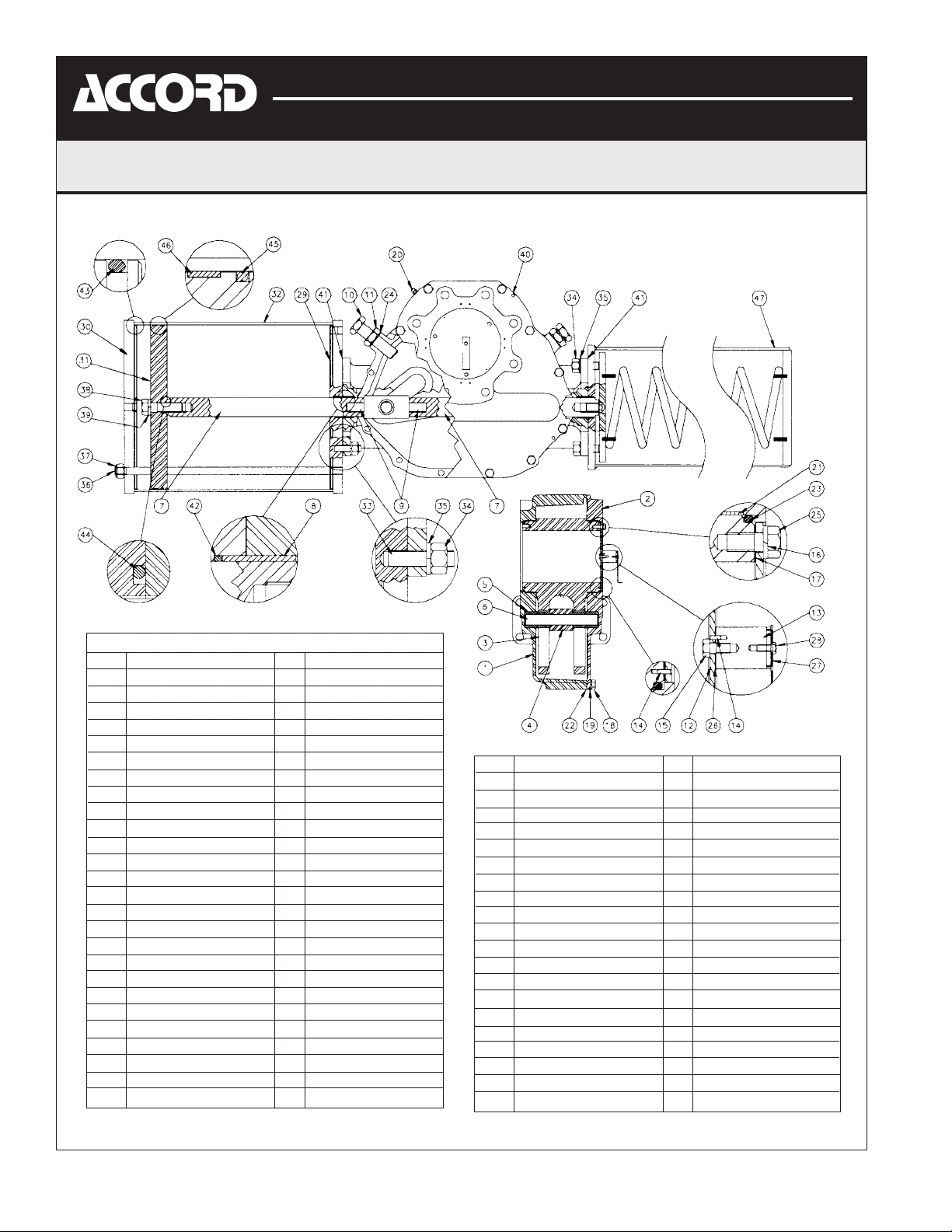
Parts and Materials
Item Description Qty Material
1 Body 1 Ductile Iron
2 Cover 1 Ductile Iron
3 Yoke 1 Ductile Iron
4 Yoke Block 1 Carbon Steel
5 Yoke Roller 4 Alloy Steel
6 Yoke Pin 1 Carbon Steel
7 Piston Rod 1 Carbon Steel
8 Rod Bushing 1 Bronze
9 Rod Stud 1 Alloy Steel
10 Stop Bolt 2 Alloy Steel
11 Stop Bolt Locknut 2 Carbon Steel/Zn
12 Indicator Plate 1 Carbon Steel
13 Accessory Coupler 1 Carbon Steel
14 Roll Pin 3 Alloy Steel
15 Coupler Bolt 1 Carbon Steel
16 Lockwasher 3 Carbon Steel/Zn
17 Indicator Plate Gasket 1 Gasket Material
18 Body Cover Bolt 12 Carbon Steel
19 Lockwasher 12 Carbon Steel/Zn
20 Pressure Relief Valve 1 Brass/Nitrile
21 Yoke Bushing 2 Steel/Teflon/Bronze
22* Cover Gasket 1 Gasket Material
23* Yoke Seal 2 Nitrile
24* Stop Bolt Thread Seal 2 Steel/N Nitrile
25 Indicator Plate Bolt 3 Carbon Steel
26* Coupler Gasket 1 Gasket Material
27 Indicator 1 Carbon Steel
Item Description Qty Material
28 Indicator Bolt 1 Carbon Steel
29 Adapter 1 Carbon Steel
30 Endcap 1 Carbon Steel
31 Piston 1 Carbon Steel
32 Cylinder 1 Carbon Steel/Chrome
33 Adapter Stud 8 Carbon Steel
34 Adapter Nut 8 Carbon Steel
35 Lockwasher 8 Carbon Steel/Zn
36 Tie Rod 4 Carbon Steel
37 Tie Rod Nut 4 Carbon Steel
38 Piston Bolt 1 Carbon Steel
39 Lockwasher 1 Carbon Steel/Zn
40 Cover Jackscrews 4 Stainless Steel
41 Adapter Gasket 1 Gasket Material
42 Piston Rod Seal 1 Nitrile
43* Endcap Seal 2 Nitrile
44* Piston Bolt Seal 1 Nitrile
45* Piston Seal 1 Nitrile
46 Piston Wear Band 1 Teflon
47 Spring Cartridge 1 Carbon/Alloy Steel
*Recommended spare parts
ACAIM028-00 (AC-98) 3/01
©
2001, Flowserve Corporation, Provo, Utah
Page 4 of 4
 Loading...