

Page 1
Installation, Operation, Maintenance Instructions
Pneumatic Diaphragm On-Off Actuators
Series 2, Types: P0, P1
Flow Control Division
Kammer Control Valves
Index
1 Using Kämmer valves and actuators correctly.
2Unpacking
3 Installation
4 Quick check
5 Maintenance
6 Remove and install actuator
7 Disassemble actuator
8 Assemble actuator
9 Troubleshooting chart
1 USING KÄMMER VALVES AND ACTUATORS
CORRECTLY
1.1 General
The following instructions are designed to assist in
unpacking, installing and performing maintenance as
required on Kämmer products. Product users and
maintenance personnel should thoroughly review this
bulletin prior to installing, operating or performing
any maintenance.
DANGER:
are designed for specific applications (e.g. with regard
to medium, pressure, temperature). For this reason
they should not be used in other applications without
first contacting the manufacturer.
1.2 Terms concerning safety
The safety terms DANGER, W ARNING, CAUTION and
NOTE are used in these instructions to highlight
particular dangers and/or to provide additional
information on aspects that may not be readily
apparent.
DANGER:
and/or substantial property damage will occur if
proper precautions are not taken.
STOP!
WARNING:
and/or substantial property damage can occur if
proper precautions are not taken
CAUTION:
or property damage can occur if proper precautions
are not taken.
In most cases Kämmer valves and actuators
indicates that death, severe personal injury
indicates that death, severe personal injury
.
indicates that minor personal injury and/
NOTE:
information, which may not be very obvious even to
qualified personnel.
Compliance with other, not particularly emphasised
notes, with regard to transport, assembly, operation
and maintenance and with regard to technical
documentation (e.g. in the operating instruction,
product documentation or on the product itself) is
essential, in order to avoid faults, which in themselves
might directly or indirectly cause severe personal
injury or property damage.
1.3 Protective clothing
Kämmer products are often used in problematic
applications (e.g. extremely high pressures, dangerous, toxic or corrosive mediums). In particular
valves with bellows seals point to such applications.
When performing service, inspection or repair
operations always ensure, that the valve and actuator
are depressurised and that the valve has been cleaned
and is free from harmful substances. In such cases
pay particular attention to personal protection
(protective clothing, gloves, glasses etc.).
1.4 Qualified personnel
Qualified personnel are people who, on account of
their training, experience and instruction and their
knowledge of relevant standards, specifications,
accident prevention regulations and operating
conditions, have been authorised by those responsible
for the safety of the plant to perform the necessary
work and who can recognise and avoid possible
dangers.
1.5 Installation
DANGER:
serial-no. and/or the tag-no. to ensure that the valve/
actuator is correct for the intended application.
Do not insulate extensions that are provided for hot
or cold services.
Pipelines must be correctly aligned to ensure that the
valve is not fitted under tension.
indicates and provides additional technical
Before installation check the order-no,
KMEIM0002-00 08.03
1
Page 2
Flow Control Division
Kammer Control Valves
1.6 Spare parts
Use only Kämmer original spare parts. Kämmer
cannot accept responsibility for any damages that
occur from using spare parts or fastening materials
from other manufactures. If Kämmer products
(especially sealing materials) have been on store for
longer periods check these for corrosion or deterioration before using these products. Fire protection for
Kämmer products must be provided by the end user .
1.7 Service / repair
To avoid possible injur y to personnel or damage to
products, safety terms must be strictly adhered to.
Modifying this product, substituting nonfactory parts,
or using maintenance procedures other than outlined
in this instruction could drastically affect performance
and be hazardous to personnel and equipment, and
may void existing warranties. Between actuator and
valve there are moving parts. To avoid injury
Flowserve provides pinch-point-protection in the form
of cover plates, especially where side-mounted
positioners are fitted. If these plates are removed for
inspection, service or repair special attention is
required. After completing work the cover plates must
be refitted.
Apart from the operating instructions and the
obligatory accident prevention directives valid in the
country of use, all recognised regulations for safety
and good engineering practices must be followed.
WARNING:
for repair or service Kämmer must be provided with
STOP!
a certificate which confirms that the product has been
Before products are returned to Kämmer
decontaminated and is clean. Kämmer will not accept
deliveries if a certificate has not been provided (a form
can be obtained from Kämmer).
1.8 Storage
In most cases Kämmer Products are manufactured
from stainless steel. Products not manufactured from
stainless steel are provided with an epoxy resin
coating. This means that Kämmer products are well
protected from corrosion. Nevertheless, Kämmer
products must be stored adequately in a clean, dry
environment. Plastic caps are fitted to protect the
flange faces and to prevent the ingress of foreign
materials. These caps should not be removed until
the valve is actually mounted into the system.
1.9 Valve and actuator variations
These instructions cannot claim to cover all details
of all possible product variations, nor in particular
can they provide information for every possible
example of installation, operation or maintenance.
This means that the instructions normally include only
the directions to be followed by qualified personal
where the product is being used for is defined
purpose. If there are any uncertainties in this respect
particularly in the event of missing product-related
information, clarification must be obtained via the
appropriate FLOWSERVE sales office.
2 UNPACKING
2.1 Each delivery includes a packing slip. When unpacking, check all delivered valves and accessories using
this packing slip.
2.2 Larger valves can be lifted using slings on the yoke
rods or, if present, on the lugs provided for this
purpose. If slings are used, attach them so that the
outer tubing or attaching parts are not damaged.
WARNING:
tre of gravity of the valve may be above the lifting
STOP!
If slings are used, be aware that the cen-
point. In this case, secure or support the valve against
rotating, to prevent damage or personnel injury.
2.3 Report transport damage to the carrier immediately.
2.4 In case of discrepancies, contact your nearest
FLOWSERVE sales office.
3 INSTALLATION
3.1 Clean tubing prior to installing.
3.2 If possible, install the valve in an upright position
(actuator on top), to ease maintenance. An upright
installation position is important with low-temperature applications, in order to keep the distance between the packing material and the medium as large
as possible. The packing material then retains the
ambient temperature as much as possible.
NOTE:
Do not insulate extension bonnets that are pro-
vided for hot or cold services
3.3 Make sure that sufficient overhead clearance above
the actuator is maintained, to allow for disassembly
of plug from the valve body.
3.4 After installing, check direction of flow again. The
direction of flow is shown by the arrow on the
housing.
3.5 If the valve is to be welded into the line, make sure that
the valve is shielded from excessive heat.
3.6 Connect supply pressure and signal lines. Control
valves are supplied with a positioner. The end connections for supply pressure and signal are clearly
marked. Series 4 actuators and positioners are suitable for max. 4.2 bar (60 psi) supply pressure. If the
supply pressure exceeds the pressure specified on
the nameplate, a pressure reducing station is required. If instrument air is not available, install an oil
separator/air filter in the air inlet line. All connections
must be leak free.
WARNING:
making mechanical contact with the actuator hous-
STOP!
Prevent other items of equipment from
ing.
4 QUICK CHECK
Before operating, check the valve as follows:
4.1 Open and close the valve, and observe the movement
of the actuator stem. The movement must be smooth
and linear.
4.2 Check for maximum stroke through change of signal
2
Page 3
Flow Control Division
Kammer Control Valves
(for pneumatic positioners, 0.2 - 1.0 bar or corresponding split-range values; for IP positioners, 4-20
or 0-20 mA).
4.3 Check all air connections for leaks.
4.4 Tighten packing nut (see table 1).
Torque
Thread PTFE Grafoil
M20 x 1,5 1 3
M30 x 1,5 6 15
M38 x 1,5 15 35
M45 x 1,5 17 40
Table 1
NOTE:
An excessively tightened gland nut can cause
excessive packing wear and can hinder the free movement of the plug stem.
4.5 Check fail-safe position. To do this, close supply
pressure and observe whether the valve opens or
closes as defined.
4.6 After use at fluctuating temperatures, re-tighten all
bolt connections and check for leaks.
5 MAINTENANCE
Check valves for correct functioning at regular intervals (at least once every 6 months) as follows. This
check can be made when installed and in many
cases without interrupting production. If internal defects are suspected, see section „Disassembly and
Assembly of Valve“.
5.1 Examine gaskets for leaks and if necessary re-tighten
bolts (see Fig. 1).
5.2 Check bellows gasket and test connection - if present
- for external leaks.
5.3 Check valve for damage caused by corrosive residues
or corrosive vapours.
5.4 Clean valve/actuator and repaint as necessary.
Warning:
STOP!
clean the actuator/valve with a damp cloth only.
5.5 Check gland nut for correct torque (see table 1).
To prevent a buildup of electrostatic charge
NOTE: With graphite packing, irregular movement of
the plug stem is normal.
WARNING:
STOP!
all moving parts. Failure to do so can lead to serious
Keep hands, hair , clothing, etc. away from
injury.
5.7 Check all accessories for firm seating.
5.8 If possible, close supply pressure and check the failsafe position.
5.9 Check stem boot for wear.
5.10 Check actuator for leaks. To do this, spray housing,
air connections and plug stem guide with leak spray
and check for any bubble formation.
5.11 Clean plug stem.
5.12 Check air filter, if present, and if necessary replace
insert.
Note:
For further information regarding service and
maintenance please contact your nearest FLOWSERVE
office.
DANGER:
On actuators with aluminium cases the
actuator springs must be renewed with original spare
parts every 10 years or after 50.000 operating hours
which ever occurs first.
NOTE: An excessively tightened gland nut can cause
excessive packing wear and can hinder the free movement of the plug stem.
5.6 If possible, open and close valve and check for maximum stroke and smooth movement of the plug stem.
Irregular movement of the plug stem may indicate
internal defects.
3
Page 4

Flow Control Division
Kammer Control Valves
18
19
20
17
16
14
13
19
20
25
15
12
12
13
28
28
29
20
15
21
29
20
15
21
15
11
26
12
12
1
2
3
4
5
2
6
7
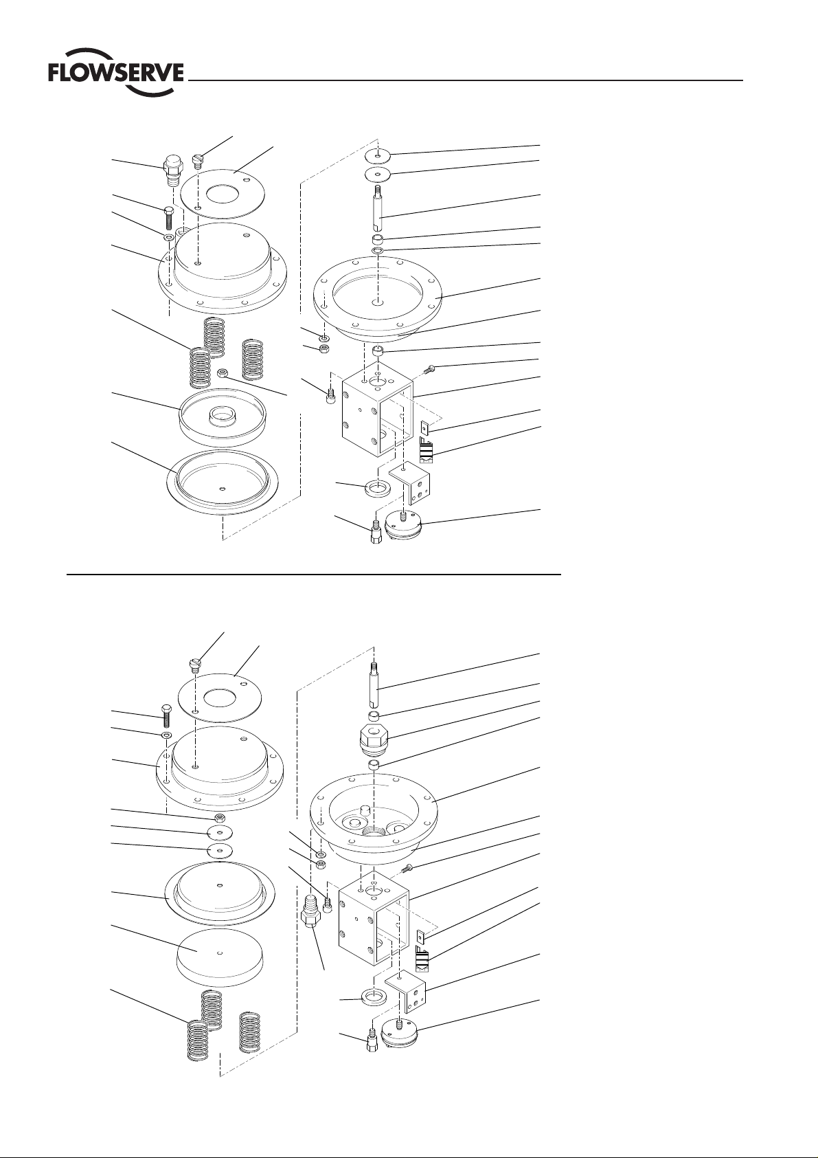
1 Actuator stem
2 Bushing
8
9
3 O-Ring, 10 x 2,4
4 Diaphragm case
5 Label
6 Screw
7 Yoke
8 Square nut
27
9 Travel indicator
10 Bracket (NAMUR)
11 Washer
12 Washer
13 Diaphragm
14 Piston
15 Nut
16 Spring set
17 Spring case
22
18 Vent plug
19 Screw
2
20 Washer
30
21 Screw
2
22 Actuator stem
23 Spring case
24* Spring (set)
23
25 Diaphragm case
26 Nut
27 Coupling
5
28 Bellows seal coupling
6
* For Actuator P0, air-to-
7
close/spring-to-open, one
central actuator spring
8
9
14
10
24*
18
11
27
26
4
Page 5
6 REMOVING AND REPLACING ACTUATOR
Flow Control Division
Kammer Control Valves
General information
All repair work is best performed when the actuator is
removed from the valve body.
However, many service repairs and adjustments can be
accomplished in the field while the actuator and valve
body are still connected to each other.
WARNING:
with the plug seated. This may cause irreparable damage
STOP!
Ensure that the plug assembly is not rotated
to the seating faces.
Always remove the yoke (7) with the actuator as an
assembly.
6.1 Remove actuator
6.1.1 On actuators with air-to-close action partially vent
actuator, on actuators with air-to-open action apply
supply pressure to raise the plug (half stroke).
CAUTION:
Galling of critical surfaces may result if the
plug is not correctly positioned between seat ring and
bonnet.
6.1.2 With a wrench, hold the actuator stem to prevent it from
rotating while using a second wrench to loosen the plug
stem locknut on the plug stem (27) or coupling screws
(28).
6.2 Replace actuator
The actuator stem must be fully extended:
Actuators with air-to-open action must be fully vented.
Actuators with air-to-close action apply supply pressure.
6.2.1 As required remove packing nut and slotted nut from
the valve bonnet.
6.2.2 Manually depress the plug stem to ensure the plug is
fully seated.
6.2.3 Place the actuator over the valve adding slotted nut,
and packing nut.
6.2.4 Thread the plug stem locknut as far as possible onto
the plug stem.
6.2.5 Engage the plug stem and coupling threads and rotate
actuator in a clockwise direction until the clearance
between the yoke base and the bonnet seating face is
around 2 mm.
WARNING: Ensure that the plug assembly is not rotated
with the plug seated. This may cause irreparable
STOP!
damage to the seating faces.
6.2.6 On actuators with air-to-close action partially vent
actuator, on actuators with air-to-open action apply
supply pressure to raise the plug (half stroke).
6.1.3 Loosen the packing nut as far as possible.
6.1.4 Loosen the slotted nut as far as possible.
6.1.5 Completely rotate the actuator off the plug stem by
continuously loosening locknut, packing nut and slotted
nut ensuring that the plug stem does not rotate in the
bonnet.
CAUTION:
Do not allow the plug to drop and impact
against the seat after turning the actuator off the plug
stem threads.
6.1.6 When the actuator is free release supply pressure and
remove actuator.
6.2.7 Tighten slotted nut.
6.2.8 With a wrench, hold the actuator stem to prevent it
from rotating while using a second wrench to tighten
the plug stem locknut against the coupling.
6.2.9 Tighten packing nut (see table 1).
6.2.10 Vent actuator and adjust travel indicator (9).
5
Page 6
Flow Control Division
Kammer Control Valves
18
19
20
17
16
14
13
19
20
25
15
12
12
13
28
28
29
20
15
21
29
20
15
21
15
11
26
12
12
1
2
3
4
5
2
6
7
1 Actuator stem
2 Bushing
8
9
3 O-Ring, 10 x 2,4
4 Diaphragm case
5 Label
6 Screw
7 Yoke
8 Square nut
27
9 Travel indicator
10 Bracket (NAMUR)
11 Washer
12 Washer
13 Diaphragm
14 Piston
15 Nut
16 Spring set
17 Spring case
22
18 Vent plug
19 Screw
2
20 Washer
30
21 Screw
2
22 Actuator stem
23 Spring case
24* Spring (set)
23
25 Diaphragm case
26 Nut
27 Coupling
5
28 Bellows seal coupling
6
* For Actuator P0, air-to-
7
close/spring-to-open, one
central actuator spring
8
9
14
10
24*
18
11
27
26
6
Page 7

Flow Control Division
Kammer Control Valves
7 DISASSEMBLE ACTUATOR
(refer to Figs. 1 and 2)
7.1.1 Remove the actuator from the valve.
WARNING:
(see Figs. 1and 2, pos. 16 or 24) are pre-tensioned.
STOP!
In many actuators the actuator springs
For this reason NEVER remove the case screws (see
Figs. 1 and 2, pos. 19) without using a suitable press
or the method described below.
7.1.2 If long (de)compression screws are not already fitted
to the actuator remove 2 diametrically opposite case
retaining screws (19).
7.1.3 Insert 2 at least 35 mm long (de)compression
screws, and tighten them with nuts (15) hand tight.
7.1.4 Remove the 2 remaining short case retaining screws
(19).
7.1.5 Unscrew the long (de)compression screws in equal
measures until the actuator springs are fully
decompressed and the upper case is loose.
7.2 Valve with action: Air-to-open
(For valve with action air-to-close proceed with 3)
(refer to fig. 1)
7.2.1 Remove the upper case half (17).
7.2.2 Remove spring set.
7.2.3 Remove coupling (27) or (28) and bracket (10).
7.2.4 Secure the actuator stem (1) with a wrench across
the flats on the stem’s lower part against rotating
and remove the nut (26).
7.2.5 Remove following parts: piston (14), diaphragm
(13), washers (12) and actuator stem (1).
7.2.6 Remove 4 screws (21) and remove yoke.
7.2.7 Remove the guide (4) and upper yoke plate (8).
7.3 Valve with action: Air-to-close
(refer to fig. 2)
7.3.1 Remove the upper case half (25).
7.3.2 Remove coupling (27) or (28) and Bracket (10).
7.3.3 Secure the actuator stem (1) with a wrench across
the flats on the stem’s lower part against rotating
and remove the nut (26).
7.3.4 Remove following parts: washers (12), diaphragm
(13), piston (14), and actuator stem (1).
7.3.5 Remove spring set (24)
7.3.6 Remove 4 screws (21) and remove yoke.
8 ASSEMBLE ACTUATOR
8.1 Valve with action: Air-to-open
(For valve with action air-to-close proceed with 5)
(refer to fig. 1)
8.1.1 Refit the actuator stem (1), washers (12), diaphragm (13) and piston (14).
8.1.2 Secure the actuator stem (1) with a wrench across
the flats on the stem’s lower part against rotating and
retighten the retaining nut (26).
8.1.3 Refit bracket (10) and coupling (27) or (28).
8.1.4 Replace spring set (16).
8.1.5 Replace the upper case half (17).
8.1.6 Insert 2 at least 35 mm long (de)compression screws
through the upper and lower actuator case halves and
tighten with nuts (15) in equal measures until the
casing halves contact.
8.1.7 Insert and tighten the 2 remaining short case retaining
screws (19).
8.1.8 As required replace the long (de)compression screws/
nuts with the short screws/nuts.
8.1.9 Refit yoke with 4 screws (21).
8.1.10 As required refit the actuator assembly to the valve.
8.2 Valve with action: Air-to-close
(refer to fig. 2)
8.2.1 Refit the actuator stem (22), spring set (24), piston
(14), diaphragm (13) and washers (12) .
8.2.2 Secure the actuator stem (1) with a wrench across
the flats on the stem’s lower part against rotating and
retighten the retaining nut (26).
8.2.3 Refit bracket (10) and coupling (27) or (28).
8.2.4 Replace the upper case half (25).
8.2.5 Insert 2 at least 35 mm long (de)compression screws
through the upper and lower actuator case halves and
tighten with nuts (15) in equal measures until the
casing halves contact.
8.2.6 Insert and tighten the 2 remaining short case retaining
screws (19).
8.2.7 As required replace the long (de)compression screws/
nuts with the short screws/nuts.
8.2.8 Refit yoke with 4 screws (21).
8.2.9 As required refit the actuator assembly to the valve.
7
Page 8

9 Troubleshooting chart
Problem Possible cause Corrective Action
Stem pulsates 1. Unstable air supply 1. Adjust air supply
2. Vent or passage blocked 2. Clean vent or passage
Actuator slow 1. Air supply too low 1. Adjust air supply
2. Diaphram case leaks air 2. Seal diaphram case
3. Spring case vent blocked 3. Renew vent
Actuator will not 1. Air supply too low 1. Adjust air supply
return to end 2. Actuator movement blocked 2. Dissassemble actuator and check
position
Actuator will not 1. Air supply not switched off 1. Adjust air supply
return to the 2. Broken actuator spring 2. Renew all actuator springs
failsafe position 3. Actuator movement blocked 3. Dissassemble actuator and check
Flow Control Division
Kammer Control Valves
Regional Headquarters
Flowserve Flowserve Flowserve
Manderscheidtstr. 19 1350 N. Mt. Springs Prkwy. 12 Tuas Avenue 20
45141 Essen Springville, UT 84663
Germany USA Singapore 638824
Telephone: +49 (0) 201 8919 5 Telephone: +1 801 489 8611 Telephone: +65 862 3332
Facsimile: +49 (0) 201 8919 662 Facsimile: +1 801 489 3719 Facsimile: +65 862 4940
Main Sales Offices (Europa, Middle east, Africa)
Flowserve Flowserve Flowserve Flowserve
von-Braun-Straße 19a 12, av. du Québec Station Road Allee du Quartz 1
48681 Ahaus 91965, Courtaboeuf Cedex Pershore, Worcestershire CH-2300 La-Chaux-de Fonds
Germany France England WR102BZ Switzerland
Telephone: +49 (0) 2561 6860 Telephone: +33 (0) 1 60 923 251 Telephone: +44 (0) 1386 55 45 51 Telephone: +41 (0) 32 925 9700
Facsimile: +49 (0) 2561 68648 Facsimile: +33 (0) 1 60 923 299 Facsimile: +44 (0) 1386 55 49 68 Facsimile: +41 (0) 32 926 5422
Flowserve Flowserve
Cnr. Bismit and Granier Str. C/O Saleh & Abdulaziz Abahsain
Jet Park Ext 3 P.O. Box 209
Boksburg
1459 Gauteng Al Khobar 31952
South Africa Saudi Arabia
Telephone: +27 397-3150 Telephone: 9663 857 3442
Facsimile: +27 397-5300/01/02 Facsimile: 9663 859 5284
8
©12.98 Flowserve Corporation. Flowserve and Kämmer are trademarks of Flowserve Corporation
All data subject to change without notice
 Loading...