

Page 1
Aceptic Valves
Series 191700 / 191800
INDEX
1 Using FLOWSERVE valves, actuators and
accessories correctly
2 Unpacking
3 Technical data
4 Safety
5 Installation
6 Disassembly and assembly
7 Disassembly
8 Assembly
9 Commissioning
10 Maintenance
1 USING FLOWSERVE VALVES, ACTUATORS AND AC-
CESSORIES CORRECTLY
1.1 Using
The following instructions are designed to assist in
unpacking, installing and performing maintenance as
required on FLOWSERVE products. Product users
and maintenance personnel should thoroughly review
this bulletin prior to installing, operating or performing any maintenance.
In most cases FLOWSERVE valves, actuators and
accessories are designed for specific applications
(e.g. with regard to medium, pressure, temperature).
For this reason they should not be used in other
applications without first contacting the manufacturer.
1.2 Terms concerning safety
The safety terms DANGER, WARNING, CAUTION and
NOTE are used in these instructions to highlight
particular dangers and/or to provide additional information on aspects that may not be readily apparent.
DANGER:
jury and/or substantial property damage will occur if
proper precautions are not taken.
WARNING:
STOP!
jury and/or substantial property damage can occur if
proper precautions are not taken.
indicates that death, severe personal in-
indicates that death, severe personal in-
CAUTION:
or property damage can occur if proper precautions
are not taken.
NOTE:
information, which may not be very obvious even to
qualified personnel.
Compliance with other, not particularly emphasised
notes, with regard to transport, assembly, operation
and maintenance and with regard to technical documentation (e.g. in the operating instruction, product
documentation or on the product itself) is essential, in
order to avoid faults, which in themselves might
directly or indirectly cause severe personal injury or
property damage.
1.3 Protective clothing
FLOWSERVE products are often used in problematic
applications (e.g. extremely high pressures, dangerous, toxic or corrosive mediums). In particular valves
with bellows seals point to such applications. When
performing service, inspection or repair operations
always ensure, that the valve and actuator are depressurised and that the valve has been cleaned and is free
from harmful substances. In such cases pay particular attention to personal protection (protective clothing, gloves, glasses etc.).
1.4 Qualified personnel
Qualified personnel are people who, on account of
their training, experience and instruction and their
knowledge of relevant standards, specifications, accident prevention regulations and operating conditions, have been authorised by those responsible for
the safety of the plant to perform the necessary work
and who can recognise and avoid possible dangers.
indicates that minor personal injury and/
indicates and provides additional technical
KMEIM9104-01 - 02.04
1
Page 2

1.5 Installation
DANGER:
Before installation check the order-no, serial-no. and/or the tag-no. to ensure that the valve/
actuator is correct for the intended application.
Do not insulate extensions that are provided for hot or
cold services.
Pipelines must be correctly aligned to ensure that the
valve is not fitted under tension.
Fire protection must be provided by the user.
1.6 Spare parts
Use only FLOWSERVE original spare parts.
FLOWSERVE cannot accept responsibility for any
damages that occur from using spare parts or
fastening materials from other manufactures. If
FLOWSERVE products (especially sealing materials)
have been on store for longer periods check these for
corrosion or deterioration before using these products.
Fire protection for FLOWSERVE products must be
provided by the end user.
1.7 Service / repair
To avoid possible injury to personnel or damage to
products, safety terms must be strictly adhered to.
Modifying this product, substituting nonfactory parts,
or using maintenance procedures other than outlined
in this instruction could drastically affect performance
and be hazardous to personnel and equipment, and
may void existing warranties. Between actuator and
valve there are moving parts. To avoid injury
FLOWSERVE provides pinch-point-protection in the
form of cover plates, especially where side-mounted
positioners are fitted. If these plates are removed for
inspection, service or repair special attention is
required. After completing work the cover plates must
be refitted.
1.8 Storage
In most cases FLOWSERVE products are
manufactured from stainless steel. Products not
manufactured from stainless steel are provided with
an epoxy resin coating. This means that FLOWSERVE
products are well protected from corrosion.
Nevertheless FLOWSERVE products must be stored
adequately in a clean, dry environment. Plastic caps
are fitted to protect the flange faces to prevent the
ingress of foreign materials. These caps should not
be removed until the valve is actually mounted into
the system.
1.9 Valve and actuator variations
These instructions cannot claim to cover all details of
all possible product variations, nor in particular can
they provide information for every possible example
of installation, operation or maintenance. This means
that the instructions normally include only the
directions to be followed by qualified personal where
the product is being used for is defined purpose. If
there are any uncertainties in this respect particularly
in the event of missing product-related information,
clarification must be obtained via the appropriate
FLOWSERVE sales office.
2 UNPACKING
Each delivery includes a packing slip. When unpacking,
check all delivered valves and accessories using this
packing slip.
Report transport damage to the carrier immediately.
In case of discrepancies, contact your nearest
FLOWSERVE location.
STOP!
2
Apart from the operating instructions and the
obligatory accident prevention directives valid in the
country of use, all recognised regulations for safety
and good engineering practices must be followed.
WARNING:
Before products are returned to
FLOWSERVE for repair or service FLOWSERVE must
be provided previously with a certificate which confirms that the product has been decontaminated and
is clean. FLOWSERVE will not accept deliveries if a
certificate has not been provided (a form can be obtained from FLOWSERVE).
Page 3
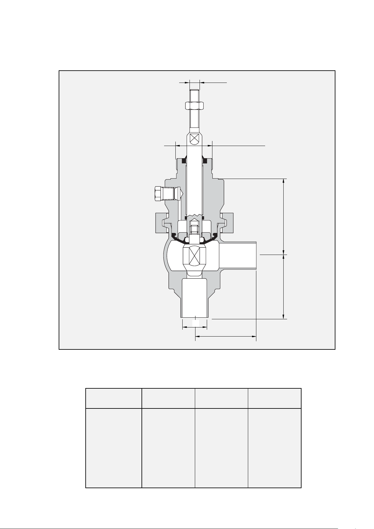
3 TECHNICAL DATA
M 10
M 38 x 1,5
B
b ⇒
A
a ⇑
C
A
Figure 1
DN ABC
DIN 11850, Series 2 191700/191800
10 / 3/8˝60 81 10
15 / 1/2˝60 81 16
20 / 3/4˝60 81 20
25 / 1˝ 65 81 26
32 / 1/ 1/4˝70 81 32
40 / 1/ 1/2˝75 82 38
50 / 2˝ 85 84 50
65 / 21/2˝ 100 105 66
80 / 3˝ 110 109 81
100 / 4˝ 120 115 100
3
Page 4

3.1 Application Control Valve
3.8 Surfaces
3.2 Pressure rating PN 10
3.3 Temperature range 0 °C to 100 °C
3.4 Valve function
To ensure optimum valve function, observe the flow
direction from connection a to connection b.
3.4.1 Function: air-to-open – spring-to-close
Product flow direction a ⇒ b
(see fig. 1)
Product flow direction closed by spring force.
3.4.2 Function: spring-to-open – air-to-close
Product flow direction a ⇒ b
(see fig. 1)
Product flow direction closed by air force.
3.5 Material data
Seals in contact with the medium
In contact with medium Ra ≤ 0,6 µm
Ra ≤ 0,5 µm Elec.-polished (opt.)
Ra ≤ 0,4 µm Elec.-polished (opt.)
Not in contact with medium Metal, turned bright
3.9 Valve connection piping
Installation position
Vertical, to ensure valve and line drain free.
3.10 Connection types
DIN 11850 series 2 (DN10 - 100) weld ends
ISO 2037 / BS 4825 weld ends
DIN EN ISO 1127 weld ends
DIN 11864 Form A threaded connection
DIN 11864 Form A flange connection
DIN 32676 clamp connection
ISO 2852 clamp connection
3.11 Pipe connection
Valve plug 1.4435
Aseptic diapragm TFM / EPDM
Operating temperature max. 100° C
Sterilisation temperature 130° C
Operating pressure max. 1.6 Mpa
Seals not in contact with the medium
O-Rings Silicon
Stainless steels
In contact with the medium 1.4404
Not in contact with the medium 1.4301
3.6 CIP cleaning agents
Nitric acid 3% / Temperature 80° C
Soda lye 3% / Temperature 80° C
3.7 SIP sterilisation agents
Hot water / Temperature 130° C
Steam / Temperature 130° C
Separable (for disassembly).
3.12 Welding instruction
See
welding instructions (sec. 5.4).
3.13 Installation
See
assembly and disassembly instructions (sec. 6).
3.14 Electrical and pneumatic connections
Assemble after fitting the valve.
3.14.1 Electrical connections
WARNING:
STOP!
qualified electrician only.
Electrical connections to be made by a
• Observe valid VDE-EVU and other local regulations.
• Check operating voltage and amperage of specific
parts before connection.
3.15 Quality of supply air
Pressure 6 bar (87 psi)
Solid particles Particle size max. 5 mm (0.4 in.)
Particle density max. 5 mg/m
(quality class 3)
Water content Dew point +2° C (35.6 °F)
(quality class 3)
Oil content Oil free, max. oil content
25 mg/m3 (quality class 3)
3
4
Page 5

4 SAFETY
5.3 Installation Guidelines
The valves described in this documentation are designed and produced so that they do not present any
hazard for the operating and service personnel or for
the system, in which the valves are installed, when
handled properly observing all important instructions
and safety precautions.
All installation and removal work, performed within the
scope of maintenance or repair to the valves, should be
accomplished only by trained personnel. When assembling or disassembling, observe the installation
instructions. Proceed precisely as specified in the installation and removal instructions to prevent severe
injury to the operating and service personnel.
The operator of the system is responsible for ensuring
that the installation, operating and maintenance personnel assigned have the required qualifications. The
operator is also responsible for ensuring that the personnel in question are familiar with the documentation
and safety regulations.
The values listed in the chapter “
Technical Data”
, such
as pressure, temperature, installation locations, etc.,
should be observed under all circumstances.
All materials and sealing elements must be suitable for
these operating conditions and the media, with which
the valves come into contact. The system operator is
solely responsible for all risks and consequences resulting from failure to observe these operating parameters. Unauthorized modifications to the valves have
an effect on the intended application and are not permissible.
In addition to these instructions, all local safety and
accident prevention regulations apply.
5.3.1 Installation Space
Before starting installation determine and define the
connection axes. Take installation dimensions from
dimension drawings. Provide for space for operation as well as service.
5.3.2 Installation
Do not subject to pressure or tension.
5.3.3 Installation Position
Vertical, to ensure that valve and line run empty.
5.4 Welding Guidelines
Range of application Welding between weld connections
and piping acc. to DIN 11850 Series 2
Welding procedure TIG (tungsten Inert gas welding)
Type of weld • Prepare weld acc to DIN 2559
(joint shape I / for I-welds)
• Welds conforming to EN 25817
⇒ evaluation group B (high)
butt weld I-joint acc. to DIN 8532
5.4.1 Welding in valves
Installation state Single-piece body
CAUTION:
To prevent damage to sealing materials
and functioning parts, always weld the body in a disassembled state. Disassemble according to disassemble instructions.
5 INSTALLATION
5.1 General Instructions
We urgently recommend having the installation
work accomplished by trained, expert personnel.
5.2 Delivery Status
The valves are tested at the factory and ready for
installation when shipped. The valve can be connected to the product line with weld ends or selected pipe connections.
5.4.2 Preparation of weld
Cut off ends of pipe even and deburr. Adjust weld-
ing ends on housing so that they make radially and
axially level contact with the piping (centering tool).
Ensure that no gap is present at the welding ends in
contact with each other, because otherwise the
forming gas would flow out reducing the corrosion
resistance of the weld.
5.4.3 Welding
Connect forming gas. Tack 3-4 points. TIG welding,
manual or orbital (machine welding).
5
Page 6

5.4.4 Welding fillers
Filler match-up table
Material to Suitable welding filler
be welded 1.4316 1.4430 1.4440 1.4519
1.4301 x
1.4306 x
1.4401 x
1.4404 x
1.4435 x x x
1.4571 x x
5.4.5 Final treatment of weld
Interior area
Final treatment of weld not required. Surface quality
can be improved at accessible points by grinding.
Exterior areas
Final treatment process:
Pickling– brushing– grinding- polishing
5.5 Cleaning
Clean entire valve thoroughly before installing.
5.6 Installation
Install according to installation instructions.
6 DISASSEMBLY AND ASSEMBLY
(see fig. 2)
6.1 Installation
To remove the complete valve, separable connec-
tions must be provided in the vicinity of the valve
connections a and b.
We recommend following distances from the valve:
Product inlet (a) : 1 x diameter
Product outlet (b) : 6 x diameter
7 DISASSEMBLY
Please observe separate documentation for disassembly of the actuator.
CAUTION:
Before disassembly:
depressurise the line to atmospheric pressure and
drain all fluid from the valve, close-off the supply air.
Valves with air-to-open actuators: tension the ac-
tuator springs using top handwheel or by applying
supply air under the membrane.
Failure to do this will cause the valve bonnet to
spring-out when the clamp is released due to the
spring pressure acting between the plug and seat.
Observe electrical connection voltage, as necessary
switch off power supply.
7.1 Disconnect pneumatic and electrical feed lines.
7.2 On air-to-open /spring-to-close actuators tension
actuator springs.
7.3 Remove actuator
Remove the coupling between the actuator stem and
the plug stem (3). Loosen the slotted nut (M38 x
1.5) on the valve bonnet (2) and remove the actuator.
7.4 Release the tension on actuator springs.
7.5 Loosen and remove the TC clamp (3).
6
CAUTION:
Do not rotate the stem (3) while the
diapragm is clamped to the body. This can damage
the stem and loosen the threaded connection between
stem(3) and plug (10) and the valve will leak.
7.6 Remove the bonnet (2) assy from the body (1).
CAUTION:
To avoid damage to the aseptic diaphragm
(6) do not turn the bonnet.
7.7 Pull the plug/stem and diaphragm assy. (4+6+10) out
of the bonnet (2).
7.8 Carefully remove the wiper (5).
7.9 Remove the O-Ring (7) which serves as the stem seal
(191800 only).
7.10 Remove the PTFE-guide (8) from the bonnet (2).
7.11 Disassemble the aseptic plug:
7.11.1 Using a suitable tool, loosen and remove the plug (10)
from the stem (4).
7.11.2 Remove the diaphragm (6) from the stem (4)
7.11.3 Unscrew the diaphragm support ring (9) from the
stem (4).
8 ASSEMBLY
Please observe separate documentation for assembly
of the actuator.
Before assembly:
Thoroughly clean all surfaces.
8.1 Place O-Ring (7) in the bonnet (2) (191800 only).
8.2 Assemble the aseptic plug:
8.21 Screw the diaphragm support ring (9) onto the stem
(4), the flat side towards the stem.
8.2.2 Place the diaphragm (10) on the plug with the convex
side facing up.
8.2.3 Screw the plug (10) with diaphragm (6) onto the stem
(4) and tighten to 25 Nm.
8.3 Place the wiper (5) in the bonnet (2).
8.4 Insert the PTFE-guide (8) carefully in the bonnet (2)
and ensure it is seated correctly to prevent damage to
the guide.
8.5 Insert the plug/stem and diaphragm assy. (4+6+10)
into the bonnet (2).
8.6 Place the outside rim of the diapragm (10) in the
shoulder on the bonnet (2).
CAUTION:
Insert the bonnet straight. Ensure that the
outside rim of the diaphragm is correctly seated in the
groove in the bonnet. To avoid damage to the aseptic
diaphragm (6) do not turn the bonnet.
8.7 Place the bonnet assy. (2) on the body (1).
8.8 Replace the TC clamp (3) and tighten securely.
8.9 On air-to-open /spring-to-close actuators tension
actuator springs.
8.10 Mount the actuator on the valve and secure with slotted nut (M38 x 1.5).
8.11 Attach the coupling between valve and actuator.
8.12 Release tension on the actuator springs.
8.13 Reconnect pneumatic and electrical feed lines and
prepare the valve for cleaning.
Page 7

Stem (4)
Wiper (5)
Bonnet (2)
PTFE-Guide (8)
TC-Clamp (3)
O-Ring, Stem seal (7)
Diaphragm support ring (9)
Aseptic diaphragm (6)
Plug (10)
Valve body (1)
Figure 2a (191700)
9 COMMISSIONING
CAUTION:
Ensure that no foreign particles are present
in the line system
9.1 Idle test
Operate valve once by actuating with compressed air,
while checking mechanical function of valve.
• TC clamp (3) seated tightly
• Check air pressure and air connections for leakage
• Check stroke path; valve spindle (4) should open
and close without jerking
Check function of the actuator based on documentation for actuator.
Clean system before operating with product for the
first time.
9.2 Test Run under Operating Conditions
Check sealing elements for leakage.
Replace defective seals as described in installation
and removal instructions.
Check mechanical functions (see idle test).
Check function of control drive (see idle test).
9.3 Initial Operation
Check valve function analog to test criteria for test
run.
Figure 2b (191800)
Figure 2
9.4 Malfunctions
Eliminate any malfunctions, which occur immediately
according to installation and removal instructions.
9.5 Malfunctions
Eliminate any malfunctions, which occur immediately
according to installation and removal instructions.
10 MAINTENANCE
Before maintenance
CAUTION:
Valves with air-to-open actuators: tension the ac-
tuator springs using top handwheel or by applying
supply air under the membrane.
Failure to do this will cause the valve bonnet to
spring-out when the clamp is released due to the
spring pressure acting between the plug and seat.
Observe electrical connection voltage, as necessary
switch off power supply.
Have repair work performed only by trained personnel authorised by the operator.
7
Page 8

10.1 Inspection
FLOWSERVE valves do not require any special service. However perform a visual check for leakage and
proper function between the maintenance intervals.
10.2 Maintenance
Maintenance intervals based on the actual operating
conditions can only be determined by the user/operator, because they depend on the following application
parameters:
• Operating time per day
• Switching intervals
• Type of product
Type of cleaning (CIP / SIP)
We recommend the following data as guide values:
• For liquids with solid constituents and tempera tures of 80° C to 100° C:
approx. every 3 – 6 months
• For liquids with solid constituents and tempera tures of approx. 60° C:
approx. every 12 months
• For liquids without solid constituents and tempera tures of max. 95° C:
approx. every 24 months
Intervals of 12 months are recommended for cleaning systems.
Naturally, the specified values assume that the sealing material is resistant to any chemicals used in cleaning.
Regional Headquarters
Flowserve EMA Flowserve America Flowserve Asia
Burrell Road, Hayward Heath 1350 N. Mt. Springs Prkwy. 12 Tuas Avenue 20
West Sussex, RH16 1TL Springville, UT 84663 638824
England USA Republic of Singapore
Telephone: +44 (0) 1444 314400 Telephone: +1 801 489 8611 Telephone: +65 862 3332
Facsimile: +44 (0) 144 3144401 Facsimile: +1 801 489 3719 Facsimile: +65 862 4940
Main Sales Offices EMA (Europe, Middle East, Africa)
Flowserve France Flowserve UK Flowserve Switzerland Flowserve Germany
7 Avenue de la Libération Station Road Allee du Quartz 1 Manderscheidtstr. 19
63300 Thiers Cedex Pershore, Worcestershire CH-2300 La-Chaux-de Fonds 45141 Essen
France England WR102BZ Switzerland Germany
Telephone: +33 (0) 4 73 80 42 66 Telephone: +44 (0) 1386 55 45 51 Telephone: +41 (0) 32 925 9700 Telephone: +49 (0) 201 8919 5
Facsimile: +33 (0) 4 73 80 14 24 Facsimile: +44 (0) 1386 55 49 68 Facsimile: +41 (0) 32 926 5422 Facsimile: +49 (0) 201 8919 662
Flowserve South Africa Flowserve Middle-East Flowserve Austria Flowserve Benelux
Units 1 and 2 C/O Saleh & Abdulaziz Abahsain Kasernengasse 6 Van Leeuwenhoekweg 6
26, Imvuba Road, Sebenza Ext 6 P.O. Box 209
Edenvale, Gauteng
Edenglen 1613 Al Khobar 31952 9500 Villach 3225 LX Hellevoetsluis
South Africa Saudi Arabia Austria The Netherlands
Telephone: +27 11 609 2094 Telephone: 9663 857 3442 Telephone: +43 (0) 424241 181-0 Telephone: +31 (0) 181 330044
Facsimile: +27 11 609 3735 Facsimile: 9663 859 5284 Facsimile: +43 (0) 424241 181 50/51 Facsimile: +31 (0) 181 330040
Flowserve Italy Flowserve Spain Flowserve Portugal Flowserve Scandinavia
Via Prealpi, 30 Luis Cabrera, 86-88 Av. Dr. Antunes Guimaraes, 1159 Gelbgjutaregatan
Cormano (Milano) E-28002 Madrid Porto 4100-082 58933 Linköping, Östergötland
Italy Spain Portugal Sweden
Telephone: +39 (0) 2663251 Telephone: +34 9 15 152 032 Telephone: +351 22 619 8770 Telephone: +46 13 316100
Facsimile: +39 (0) 26151863 Facsimile: +34 9 14 136 747 Facsimile: +351 22 619 7575 Facsimile: +46 13 136054
Flowserve Eastern Europe
12, av. du Québec
91965, Courtaboeuf Cedex
France
Telephone: +33 (0) 1 60 923 251
Facsimile: +33 (0) 1 60 923 299
8
©01.2003 Flowserve Corporation. Flowserve and Kämmer are trademarks of Flowserve Corporation
All data subject to change without notice
 Loading...