

Page 1
Installation, Operation, Maintenance Instructions
Sanitary and Hygiene Valves
Series 191 000
Series 191 600 Steam Barrier
Flow Control Division
Kammer Control Valves
1 GENERAL INFORMATION
These instructions are designed to support you when
unpacking, installing and performing maintenance
work on the valves. Users and maintenance personnel should carefully read these instructions before
installing, operating or performing maintenance
work. There is a separate set of instructions for accessories (special seat/plug fittings, diaphragm actuators, handwheels, special seats, etc.).
These instructions do not contain any information
on Kämmer positioners. For this, see corresponding instructions for the installation, maintenance,
troubleshooting, adjustment and operation of
Kämmer positioners.
To avoid damage or injury to personnel or equipment, always heed all warnings and instructions.
Unprofessional reconditioning, the use of foreign
replacement parts or the performance of other
maintenance steps than those described here, may
cause a loss of efficiency or lead to personnel injury or damage to parts, and render the warranty
void
1.1 UNPACKING
1.1.1 Each delivery includes a packing slip. When unpacking, check all delivered valves and accessories using this packing slip.
1.1.2 Report transport damage to the carrier immediately.
1.1.3 In case of discrepancies, contact your nearest dealer.
1.2 INSTALLATION
1.2.1 Clean tubing prior to installing.
1.2.2 If possible, install the valve in an upright position (actuator on top), to ease maintenance. An upright installation position is important with low-temperature
applications, in order to keep the distance between
the packing material and the medium as large as possible. The packing material then retains the ambient
temperature as much as possible.
Important: Do not insulate extension bonnets that
are provided for hot or cold services
1.2.3 Make sure that sufficient overhead clearance above
the actuator is maintained, to allow for disassembly
of plug from the valve body (see following table).
Actuator Clearance Actuator Clearance
size (mm) size (mm)
37/47 95 P2 140
38/48 140 P3 140
39/49 140 P4 140
39D/49D 140 P5 140
1.2.4 After installing, check direction of flow again.
1.2.5 If the valve is to be welded into the line, make sure
that the valve is shielded from excessive heat.
1.2.6 Connect supply pressure and signal lines. Control
valves can be supplied with a positioner. The end
connections for supply pressure and signal are clearly
marked. Actuator and positioner are suitable for max.
6 bar (87 psi) supply pressure. If the supply pressure exceeds the pressure specified on the nameplate, a pressure reducing station is required. If instrument air is not available, install an oil separator/
air filter in the air inlet line. All connections must be
free of leaks.
KMEIM9102-00 - 11.00
111.00
Page 2
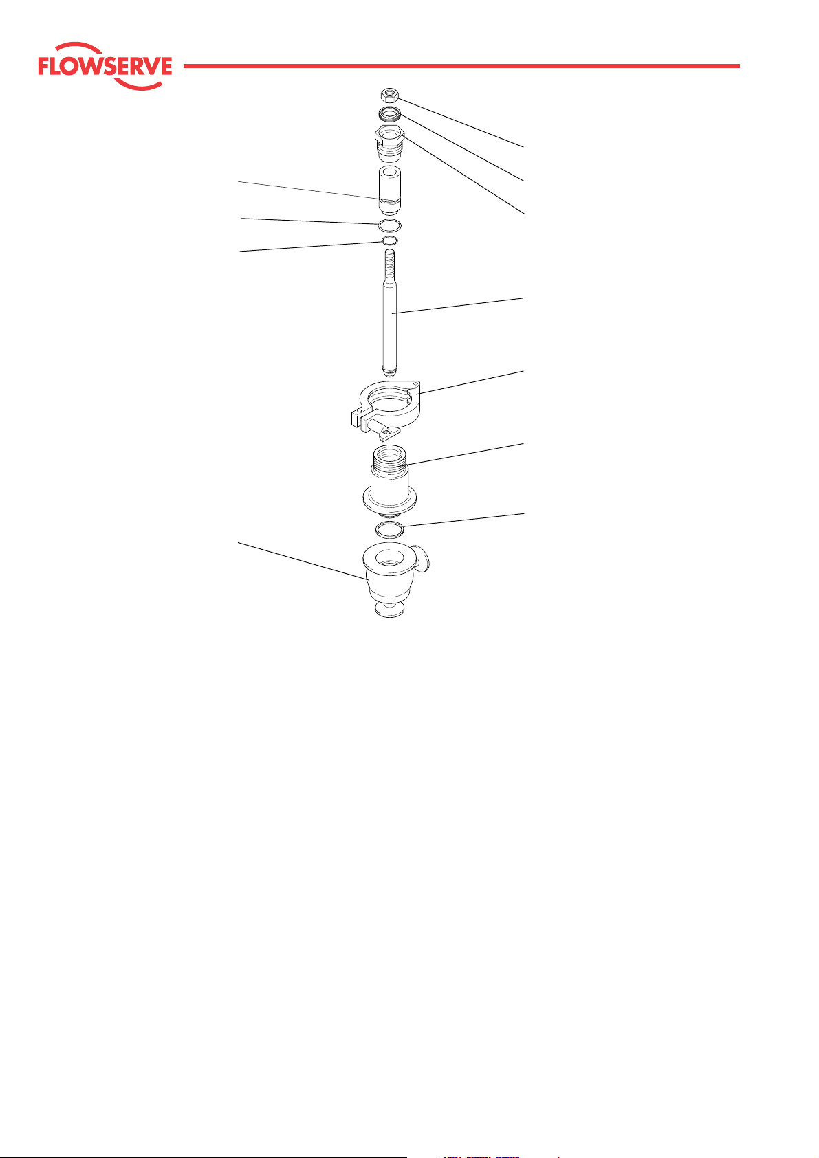
Nut
Flow Control Division
Kammer Control Valves
Guide bush
O-Ring
O-Ring
Body
Wiper ring
Packing follower
Plug
Clamp
Guide bush
O-Ring
Typical valve configuration
1.3 QUICK CHECK:
Before operating, check the valve as follows:
1.3.1 Open and close the valve, and observe the movement
of the actuator stem. The movement must be smooth
and linear.
1.3.2 Check for maximum stroke through change of signal
(for pneumatic positioners, 0.2 - 1.0 bar or corresponding split-range values; for IP positioners, 4-20
or 0-20 mA).
1.3.3 Check all air connections for leaks.
1.3.4 The packing follower must always be tight to ensure
that the packing kit (guide bush with O-Rings) functions correctly.
1.3.5 Check the wiper ring for damage.
1.3.6 Check fail-safe position. To do this, close supply pressure and observe whether the valve opens or closes
as prescribed.
Fig. 1
1.3.7 After use at fluctuating temperatures, re-tighten all
bolt connections and check for leaks.
2 MAINTENANCE
Check valves for correct functioning at regular intervals (at least once every 6 months) as follows. This
check can be made when installed and in many cases
without interrupting production. If internal defects are
suspected, see section on „Disassembly and Assembly of Valve“.
2.1 Examine gaskets for leaks and if necessary re-tighten
bolts (see Fig. 1).
2.2 Check valve for damage caused by corrosive residues
or corrosive vapours.
2.3 Clean valves and if necessary repaint.
2.4 Check that the packing follower is tight.
2 11.00
Page 3

Flow Control Division
Kammer Control Valves
2.5 If possible, open and close valve and check for maximum stroke and smooth movement of the plug stem.
Irregular movement of the plug stem may indicate
internal defects.
Note: With graphite packing, irregular movement of
the plug stem is normal.
IMPORTANT: Keep hands, hair, clothing, etc. away
from all moving parts. Failure to do so can lead to
serious injury.
2.7 Check all accessories for firm seating.
2.8 If possible, close supply pressure and check the failsafe position.
2.9 Check stem boot for wear.
2.10 Check actuator for leaks. To do this, spray housing,
air connections and plug stem guide with leak spray
and note any bubble formation.
2.11 Clean plug stem.
2.12 Check air filter, if present, and if necessary replace
insert.
3.2 Assemble valve
Attention: All worn or damaged parts must be re-
placed. Reusable parts must be clean. All consumable items such as seals, O-Rings and gaskets must
always be renewed.
3.2.1 Carefully enter the plug into the bonnet.
3.2.2 Replace body/bonnet gasket.
3.2.3 Carefully place the bonnet/plug assembly vertically
onto the body ensuring the body/bonnet gasket is
correctly seated.
3.2.4 Insert the guide bush with O-Rings into the bonnet
using an assembly bushing (see Fig. 2) and tighten
down the packing follower.
3.2.5 Place the clamp around the body an tighten the wingnut.
3 DISASSEMBLE AND ASSEMBLE VALVE
General Information
We recommend separating the actuator from the
valve before commencing repair work.
However, many maintenance and adjusting operations can be carried out with the valve installed.
Attention: Never turn plug or perform any service
on the valve while the plug is in the seat ring. Doing so may cause irreparable damage to the trim
set. To ensure against this, always hold the plug
out of the seat while working on the valve assembly.
3.1 Disassemble valve
3.1.1 Disconnect actuator from valve body
3.1.2 Loosen and remove the clamp.
3.1.3 Carefully remove the bonnet complete with plug and
packing kit..
Assembly bushing
Fig. 2 Assembly bushing
3.1.4 Carefully remove the plug from the bonnet.
3.1.5 Unscrew the packing follower and extract the packing kit from the top of the bonnet. Check the wiper
ring and O-Rings for damage.
3.1.6 Remove the body/bonnet gasket.
3.1.7 Clean and inspect all parts.
311.00
Page 4

Flow Control Division
Kammer Control Valves
Germany
Tel.: (02 01 ) 89 19 5 • Fax: (02 01 ) 89 19 600
Flowserve Essen GmbH Flowserve Essen GmbH Flowserve Essen GmbH Flowserve Essen GmbH
Sales Office Hamburg Sales Office Niederrhein Sales Office West Sales Office Maintal
Hoher Weezer Weg 27a Büdericher Straße 8 Robert-Bosch-Strasse 11
D - 47574 Goch D - 47877 Willich D - 63477 Maintal
Tel.: (02 01) 89 19 665 Tel.: (0 28 23) 9 80 02 Tel.: (0 21 54) 20 20 71 Tel.: (0 61 81) 42 404 11
Fax: (02 01) 89 19 662 Fax: (0 28 23) 9 80 03 Fax: (0 21 54) 20 20 73 Fax: (0 61 81) 42 404 29
Flowserve Essen GmbH Flowserve Essen GmbH Flowserve Essen GmbH Flowserve Essen GmbH
Sales Office Frankfurt Sales Office Südwest Sales Office Augsburg Sales Office Ost
Steinweg 22 Am Mühlhübel 13 Staatsstraße 10 Oberhasel 18
D - 65824 Schwalbach a. Ts. D - 67686 Mackenbach D - 86450 Altenmünster D - 07407 Kirchhasel
Tel.: (06196) 85 203 Tel.: (06 374) 99 27 84 Tel.: (0 82 95) 9 00 03 Tel.: (0 36 72) 46 46 82
Fax: (06196) 84 462 Fax: (06 374) 99 27 85 Fax: (0 82 95) 9 00 04 Fax: (0 36 72) 46 46 89
FRANCE USA / CANADA SWITZERLAND
Flowserve S.A.S. Flowserve (FCD) Flowserve S.A.
SEREG KAMMER VALVES, INC. Kammer Vannes.
12, av. du Québec, BP645 1300 Parkway View Drive Allée du Quartz 1
F- 91965 Courtaboeuf Cedex Pittsburgh, Pa 15205 U.S.A. CH-2300 La Chaux-de-Fonds
Flowserve Essen GmbH
Kammer Ventile
Manderscheidtstrasse 19
D-45141 Essen
Tel.: +33 1 60 92 32 87 Tel.: +1 412 787 - 8803 Tel.: +41 (0) 32 925 9700
Fax : +33 1 60 92 32 99 Fax: +1 412 787 -1944 Fax: +41 (0) 32 926 5422
AUSTRALIA AUSTRIA DENMARK FINLAND
Flowserve Australia PTY LTD Flowtec Industrietechnik GmbH Scana Godtkjær & Armatur as KONTRAM OY
14 Dalmore Drive Weinitzstrasse 1 Kong Svends Vej 65 PO. Box 88
Scoresby VlCTORlA 3179 8045 Graz 2765 Smorum 02201 Espoo
AUSTRALIA AUSTRIA DENMARK FINLAND
Tel.: +61 3 9764 0060 Tel.: +43 (0) 316 69 70 69-0 Tel.: +45 44 20 00 00 Tel. +358 9 8866 4500
Fax: +61 3 9764 0013 Fax: +43 (0) 316 69 70 69-9 Fax: +45 44 20 00 01 Fax: +358 9 8866 4599
GREAT BRITAIN IRELAND ISRAEL ITALY
Flowserve Flexachem Manufacturing Ltd TECHNOMAD LTD EUROVALVE S.R.L.
Station Road, Pershore Donnybrook Commercial Centre 19 Hashikma Str. Via Camicie Rosse 11
Worcestershire, WR10 2BZ Douglas, Cork Azor 58009 20090 Opera (Ml)
ENGLAND IRELAND ISRAEL ITALY
Tel.: +441386 554 551 Tel.: +353 21 363742 Tel.: +972 3 5585550 Tel.: +390 2 57 6018 45
Fax: +441386 554 968 Fax: +353 21 891297 Fax: +972 3 5585090 Fax: +390 2 57 6017 00
JAPAN NETHERLANDS NORWAY R. O. C.
TOKO VALEX Co., Ltd Conovalve B.V. NOR Instruments A.S. Eagle Process Service Ud.
2-17, 4-chome, Matsushima Postbus 270 Jerikoveien 26 Suite 4, 5th Floor No. 312
Edogawa-Ku, Tokyo 3100 AG Schiedam 1067 Oslo Chung Hsiao E. Road, Sec. 4
JAPAN 132 NETHERLANDS NORWAY TAIWAN
Taipei, Taiwan, R. O. C.
Tel.: +81 3 3655 6769 Tel.: +31 10 4 71 53 33 Tel.: +47 2210 05 00 Tel.: +8862 2751 6197
Fax: +81 3 3655 5181 Fax: +31 10 4 70 44 82 Fax: +47 2210 0510 Fax: +8862 2781 4640
SINGAPORE SOUTH AFRICA SWEDEN
Valtek Asia Pacific Operations Valtek South Africa (Pty.) Ltd alnab
c/o Durco-Valtek Asia P. O. Box 9279 Ögärdesvägen
12, Tuas Avenue 20 Edenglen 1613 433 86 Partille
Singapore 2263
SINGAPORE SOUTH AFRICA SWEDEN
Tel.: +65 862 3332 Tel.: +2711 609 2094-96 Tel.: +46 31 44 94 50
Fax: +65 862 4940 Fax: +2711 609 3735 Fax: +46 31 44 94 55
4 11.00
©09.2000 Flowserve Corporation. Flowserve and Kämmer are trademarks of Flowserve Corporation
All data subject to change without notice
 Loading...