

Page 1

Valtek Logix 1400
Digital Positioner
GENERAL INFORMATION
The following instructions are designed to assist in
unpacking, installing and performing maintenance as
required on Valtek® Logix™ 1400 digital positioners.
Series 1000 is the term used for all the positioners herein;
however, specific numbers indicate features specific to
a model (i.e. Logix 1400 digital positioner indicates that
the positioner uses FOUNDATION™ fieldbus protocol). Prod-
uct users and maintenance personnel should thoroughly
review this bulletin prior to installing, operating, or performing any maintenance on the valve.
More detailed operation instructions are included in other
manuals in the owner’s manual binder; refer to them
when more information is needed.
Separate Flowserve Installation, Operation, Maintenance
instructions cover the valve (IOM 1 or IOM 27) and
actuator (IOM 2 or IOM 31) portions of the system and
other accessories. Refer to
Installation & Reference Guide
implementation. Refer to the appropriate instructions
when this information is needed.
To avoid possible injury to personnel or damage
to valve parts, users must strictly adhere to
WARNING and CAUTION notes. Modifying this
product, substituting non-factory or inferior parts,
or using maintenance procedures other than
outlined could drastically affect performance or
be hazardous to personnel and equipment and
may void existing warranties.
Logix 1400 Digital Positioner
for details on fieldbus
WARNING: Standard industry safety practices must
be adhered to when working on this or any other
process control product. Specifically, personal
protective and lifting devices must be used as
warranted.
Unpacking
1. While unpacking the Logix 1400 positioner, check
the packing list against the materials received. Lists
describing the system and accessories are included
in each shipping container.
2. When lifting the system from the shipping container,
position lifting straps in a way that avoids damaging
mounted accessories. Systems with valves up to
six inches may be lifted by actuator lifting ring. On
larger systems, lift unit using lifting straps or hooks
through the yoke legs and outer end of body.
WARNING: When lifting a valve/actuator assembly with lifting straps, be aware the center of
gravity may be above the lifting point. Therefore,
support must be given to prevent the valve/
actuator from rotating. Failure to do so can cause
serious injury to personnel or damage to nearby
equipment.
3. In the event of shipping damage, contact the shipper
immediately.
4. Should any problem arise, contact a Flowserve
representative.
Valtek Part No. 164713 46-1
Page 2
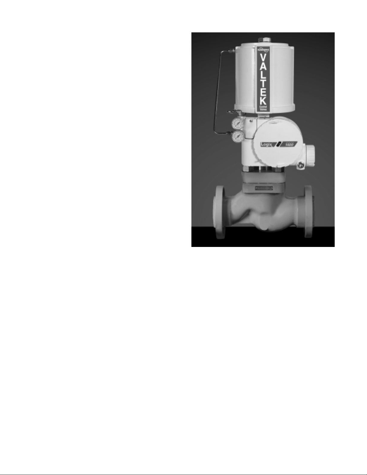
Table of Contents
General Information .................................................... 1
Unpacking .................................................................. 1
Logix 1400 Digital Positioner Overview ...................... 2
Specifications ............................................................. 3
Positioner Operation ................................................... 3
Tubing Positioner to Actuator ..................................... 4
Wiring and Grounding Guidelines ................................ 4
Driver Module Assembly ............................................. 5
Spool Valve Cover ...................................................... 6
Regulator .................................................................... 7
Internal Coalescing Filter ............................................ 7
Main PCB Assembly .................................................. 7
Collector Board ........................................................... 7
Field Terminations ...................................................... 8
Stem Position Sensor................................................. 8
LED Indicators ............................................................ 9
Re-Cal Button ............................................................. 9
Checking or Setting Internal Regulator Pressure ...... 10
Checking or Setting the Driver Module
Minimum Pressure ............................................... 10
Linear Mark I Valve Mounting................................... 11
Standard Rotary Mounting Procedure ....................... 12
Optional Rotary Mounting Procedure ........................ 13
Troubleshooting the Logix 1400 Digital Positioner .... 13
Theory of Operation.............................................. 13
Mounting and Installation ......................................... 15
Calibration ................................................................ 16
Control and Tuning ................................................... 16
Alarms ...................................................................... 18
Alerts ........................................................................ 19
Travel Accumulator .................................................. 20
Cycle Counter ........................................................... 20
Position Deviation ..................................................... 20
Advanced Features .................................................. 20
Glossary and Definitions ........................................... 23
Transducer Block Signature Parameters .................. 24
Exploded View of Positioner..................................... 27
Available Spare Parts Kits ....................................... 28
Troubleshooting Tables ............................................ 29
Positioner Mounting Kits........................................... 32
Logix 1400 Digital Positioner
Logix 1400 Digital Positioner Overview
The Logix 1400 digital positioner is a two-wire, FOUNDATION
fieldbus compliant, digital valve positioner. The Logix
1400 digital positioner also utilizes the fieldbus protocol
to allow two-way remote communications with the positioner. The Logix 1400 digital positioner can control both
double- and single-acting actuators with linear and rotary
mountings.
Since the positioner is insensitive to supply pressure
changes and can handle supply pressures from 35 to 150
psig, a supply regulator is usually not required; however,
an air filter is required due to the close clearances in the
spool assembly.
NOTE: The air supply should conform to ISA Standard
S7.3 (a dew point at least 18° Fahrenheit less than
ambient temperature, particle size below one micron, and
oil content not to exceed one part per million).
46-2 Flowserve Corporation, Valtek Control Products, Tel. USA 801 489 8611
Page 3
Specifications
Electrical Specifications
ylppuSrewoPsubdleif,eriw-owT
ylppuS.B.FCDV0.23-0.9
wardtnerrucmumixaMAm22
snoitacinummoCFNOITADNUO subdleif
NI Configurator Software Specifications
retupmoCrossecorp68408muminiM
,TNro59swodniWgninnur
BM-23(yromemlatotBM-61
BM-02,)dednemmocer
evirdyppolfhcni-5.3
rotacinummocBF
drac
)snoitporofINtcatnoc(
Positioner Specifications
dnabdaeDelacslluf%1.0<
siseretsyHelacslluf%2.0<
ytilibataepeRelacslluf%5.0<
ytiraeniL,)yrator(%5.0<
tanoitpmusnoCriA
)grab4(gisp06
MFCS%3.0<
3
mN5.0(
)rh/
Physical Specifications
gnitarepO
egnaRerutarepmeT
gnisuoHdetniap-redwop,tsaC
thgieW)gk9.3(sdnuop5.8
o
04-
o
04-(
o
581+otF
F
o
58+otC
)C
leetssselniats,munimula
sdnuop5.02munimula
leetssselniats)gk3.9(
Hazardous Area Certifications
foorPnoisolpxE,1viD,1ssalCASC/MF
gnidnep,D,C,BspuorG
eno,ecapsksiddrahelbaliava
evidnecninoN,2viD,1ssalCASC/MF
gnidnep,D,C,B,AspuorG
rotarugifnocINhtiwdeilppuS
efaSyllacisnirtnI,1viD,1ssalCASC/MF
gnidnep,D,C,B,AspuorG
CE Mark Qualifications
evitceriDCME
CEE/633/98
22055NE
elacslluf)raenil(%8.0
evitceriDDVLelbacilppAtoN
04105VNE,2-4-00016NE
1-18005NE,4-4-00016NE
1-18005NE,2-28005NE
CDV57<;CAV05<sitinU
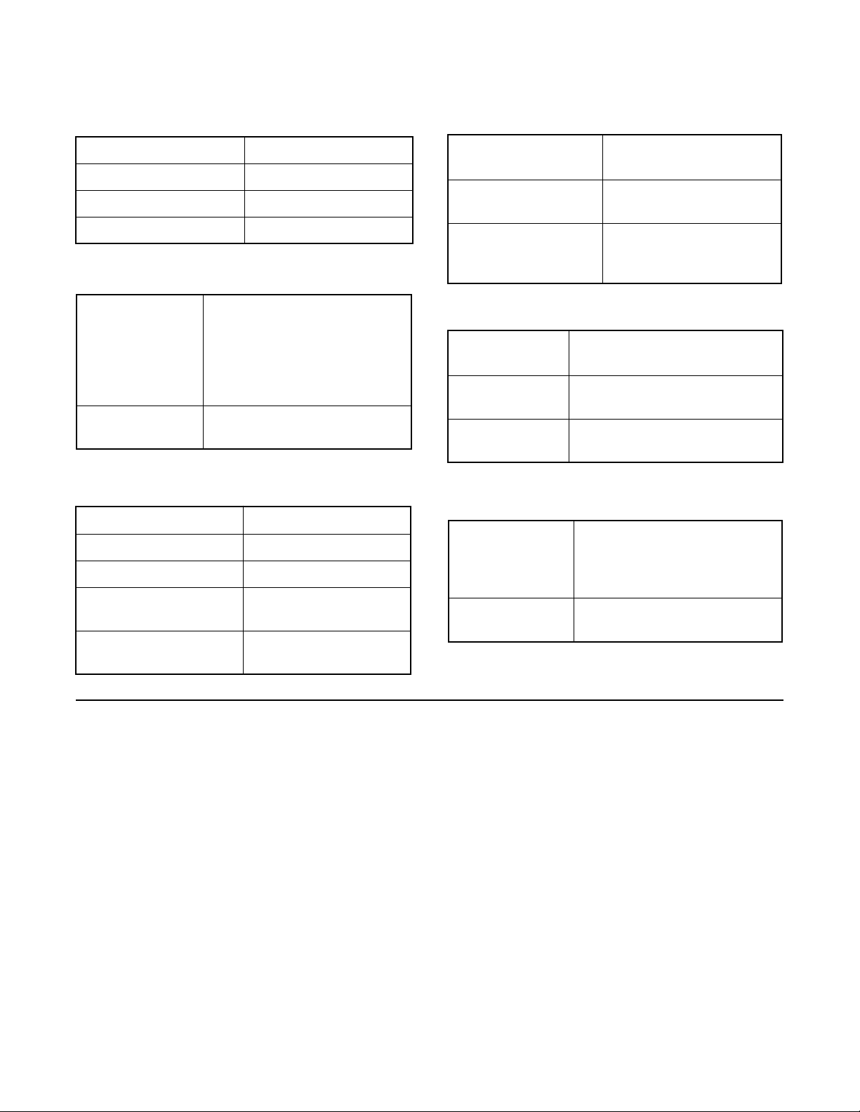
Positioner Operation
The Logix 1400 positioner is an electric feedback instrument. Figure 1 shows a Logix 1400 positioner installed on
a double-acting actuator for air-to-open action. Positioning is based on a balance of two signals: one proportional
to the command input signal and the other proportional to
the valve stem position.
The supply pressure for the positioner pressure modulator is tapped off the main supply and is filtered as it
passes through a field-replaceable, coalescing filter
element in the module. This air passes through an
internal pressure regulator that regulates it to approximately 22 psig. The air then passes through an orifice
that restricts the flow and air consumption.
The pressure modulator further controls the air from 6-12
psig, using a spring-diaphragm flapper that is attracted
by an electromagnet to a nozzle. A temperature compen-
sated hall effect sensor mounted on a circuit board
senses the spool valve position. The hall effect sensor
and circuitry create an inner feedback loop, which determines how much current to send to the electromagnet for
a desired spool valve position. The electromagnet in the
feedback loop varies the nozzle-flapper spacing, which
regulates the output pressure between 6 and 12 psig,
proportional to the digital positioning algorithm.
When the command and stem position signals are equal,
the system will be in equilibrium and the valve stem will
be in the position called for by the command signal. If
these opposing signals are not equal, the spool valve will
move up (or down) and, by means of the pressure
modulator, change the output pressures and flow rate.
This will cause the actuator piston to move until the
signal of the position sensor equalizes with the
command signal.
46-3Flowserve Corporation, Valtek Control Products, Tel. USA 801 489 8611
Page 4
Air-to-Open
Configuration
Flame Arrestors
Spool Valve
Exhaust
OUTPUT 1
Collector Board
Pressure Sensor
Air Supply
Digital Position
Algorithm
LED
Dis-
play
OUTPUT 2
Exhaust
OO
Stem Position Sensor
Hall Effect Sensor
Electromagnetic Coil
Nozzle
Flame
Arrestor
Figure 1: Logix 1000 Digital Positioner Schematic
Detailed Sequence of Positioner Operations
The positioner operates on a pressure equilibrium principle with a spool valve apportioning supply to the
actuator. An increase in the command signal causes the
modulator pressure to increase, pushing the spool assembly upward from its equilibrium position. This opens
the spool valve ports, supplying air to output 1 and
exhausting air from output 2. This causes the actuator
piston to move upward.
The upward motion of the piston is transmitted back to
the positioner through the stem-position feedback linkage. The piston continues to stroke upward until the
stem-position signal of the sensor increases sufficiently
to counter the command signal being sent to the control
algorithm. At this point, the spool is at its equilibrium
position as the pressures in the cylinder stabilize and the
air flow to the actuator decreases. The computer will then
make small adjustments to fine-tune the desired position
and compensate for changes in dynamic loading.
A decrease in the command signal reverses the
described actions, causing a proportional downward
movement of the actuator piston and stem.
Tubing Positioner to Actuator
Proper tubing orientation is critical for the positioner to
function correctly and have the proper failure mode.
Referring to Figure 1 note that for air-to-open valves, the
output 1 port of the positioner manifold is tubed to the
bottom side of the actuator. The output 2 port of the
Main PCB Tray
Ribbon Cable
Flame Arrestor
Filter
Regulator
Orifice
Flapper
positioner manifold is tubed to the top side of the
actuator. For air-to-close valves the above configuration
is reversed.
Wiring and Grounding Guidelines
Input Cable Shielding (Figure 2)
The fieldbus signal to the Logix 1400 digital positioner
should be in shielded cable. Shields must be tied to a
ground at only one end of the cable to provide a place for
environmental electrical noise to be removed from the
cable. In general, shield wire should be connected at the
source.
Cable Requirements
The Logix 1400 digital positioner utilizes the fieldbus
communication protocol. Refer to Fieldbus Foundation
document AG-140, Wiring and Installation 31.25 kbit/s,
Voltage Mode, Wire Medium Application Guide for full
information on wiring and building fieldbus networks.
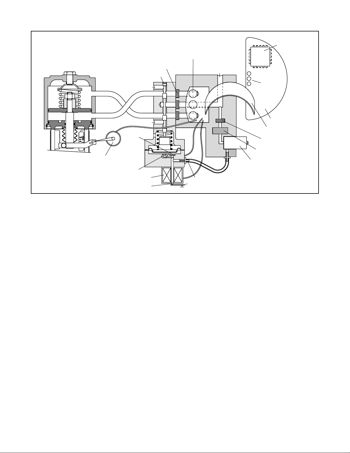
Grounding Screw
The green grounding screw, located inside the termination cap, should be used to provide the unit with an
adequate and reliable earth ground reference.
This ground should be tied to the same ground as the
electrical conduit. Additionally, the electrical conduit
should be earth grounded at both ends of its run. The
green grounding screw must not be used to terminate
signal shield wires.
46-4 Flowserve Corporation, Valtek Control Products, Tel. USA 801 489 8611
Page 5
Field Terminations
FB Connection
Terminals
Housing EARTH
Terminal
Shielded
Cable
Ground
Fieldbus
connection
Figure 2: Field Termination
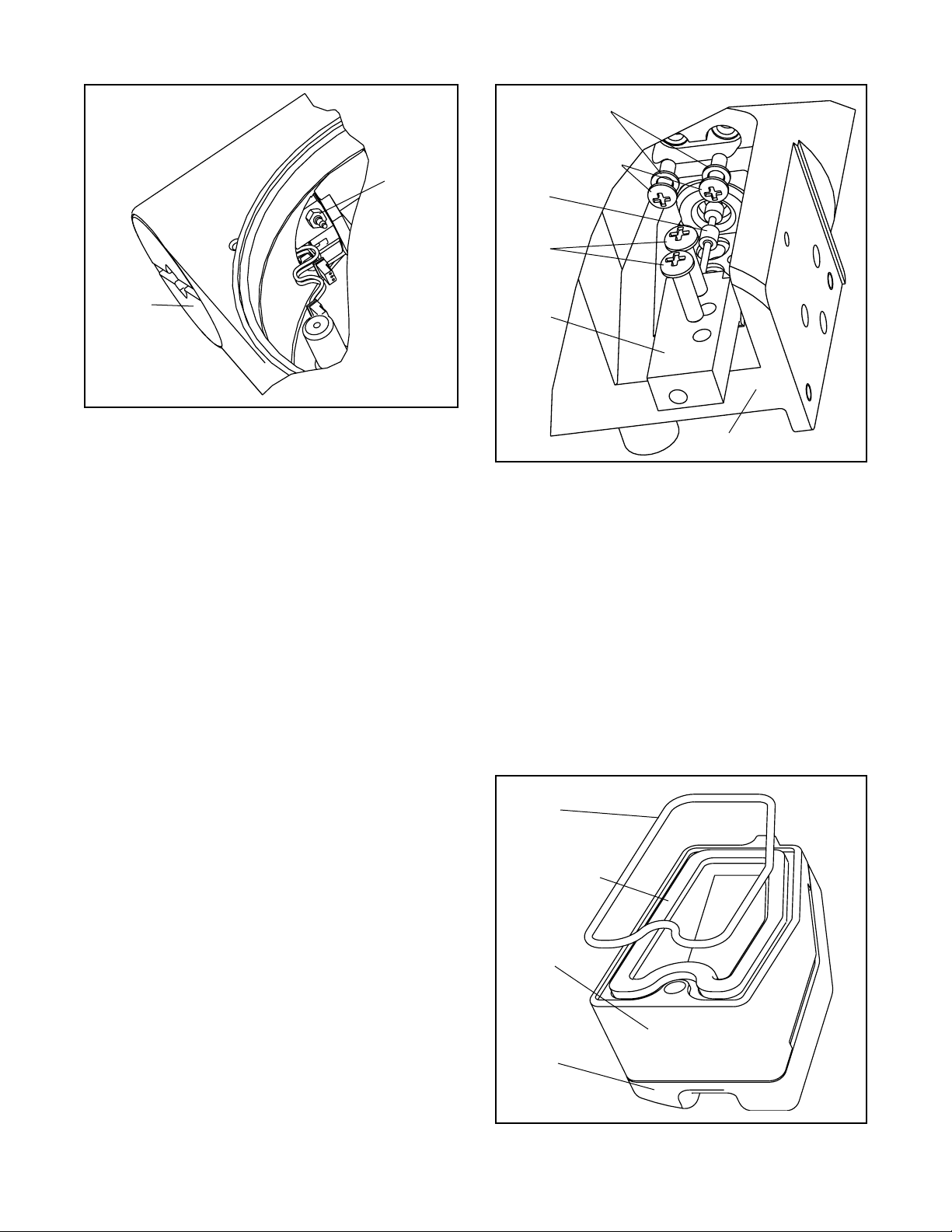
Driver Module Assembly
The driver module assembly moves the spool valve by
means of differential pressures on its diaphragm. Air is
routed to the module from the interface plate through a
hose that connects to the assembly through a hose barb
with an integral orifice. Wires from the module connect
the hall effect sensor and the pressure modulator coil to
the collector board.
Driver Module Assembly Replacement
To replace the driver module assembly, refer to Figures
3 - 5, 7 and 19 then proceed as outlined below. The
following tools are required:
1
/4-inch open-end wrench
1
/2-inch hex wrench
Phillips screwdriver
Driver Module removal tool
1. Make sure valve is bypassed or in a safe condition.
2. Disconnect the power and air supply to the unit.
3. Remove the driver module cover, using a
wrench (Figure 4). Do not force the cover. If undue
resistance is encountered, use the slots to loosen
cover.
4. Remove the spool valve cover by removing the
screw and sliding the cover assembly backwards
until the tab is clear of the slot. It is not necessary
to remove the sheet metal cap from this assembly
(Figure 7).
5. Being careful not to lose the nylon washers, remove
the two phillips-head screws that attach the driver
module to the main housing (Figure 5).
6. Remove the spool valve block by removing the two
phillips-head screws and carefully sliding the block
off the spool (Figure 5).
1
/2-inch hex
CAUTION: The spool (extending from the driver
assembly) is easily damaged. Use extreme caution when handling driver assembly.
7. Remove the tubing from the orifice in the driver
module assembly. Using a
1
/4-inch open-end wrench,
remove the orifice from the driver module (Figure 4).
8. Remove the two wiring connections that link the
driver module assembly to the collector board.
(Figure 4).
9. Feed the wires back through the housing so they
extend backward toward the driver module opening.
This will allow the driver module to thread out without
tangling the wires.
10. Grasp the driver module cap with the driver module
removal tool and rotate the entire driver module
counter clockwise to remove. After it is threaded out,
carefully retract the driver module from the housing
to avoid damaging the spool.
11. Take the new driver module and verify that the O-ring
and boot are in place. Lay the wires back along the
modulators as shown in Figure 3 and hold in place.
12. Gently direct the driver module into the housing bore,
making sure the spool does not hit the housing. Turn
driver module clockwise to thread it into the housing.
Continue rotating the module until it bottoms out.
13. Once the threads are fully engaged, rotate the driver
module counter clockwise until the flat on the driver
module and the flat on the housing are aligned. This
will align the screw holes for the next step (Figure 3).
14. Verify that nylon gaskets are in the counter bores in
the driver module retaining screw holes as shown in
Figure 5.
15. Insert two driver-to-housing screws into the driver
housing through the counter-bored holes in the
positioner main housing. Tighten evenly with a phillips
screwdriver.
Collector Board
Pressure Modulator
Connection
Hall Sensor
Connection
Flat in Housing
Protective
Boot
O-ring
Orient this flat parallel
to flat in housing
Minimum Pressure Set Screw (factory calibrated)
Driver Module Assembly
Install orifice after driver
module is in housing
Figure 3: Driver Module Assembly
46-5Flowserve Corporation, Valtek Control Products, Tel. USA 801 489 8611
Page 6
Orifice
Nylon Gaskets
Driver to
Housing Screws
Spool
Spool
Valve
Screws
Driver
Module
Cover
Figure 4: Driver Module Orifice
16. Feed the driver module wires into the main chamber
of the housing and connect them to collector board.
17. Verify that the three O-rings are in the counter-bores
on the machined platform where the spool valve
block is to be placed (Figure 19)
18. Carefully slide the block over the spool, using the
machined surface of the housing base as a register
(Figure 5). Slide the block toward the driver module
until the two retaining holes line up with the threaded
holes in the base.
19. Install two spool-valve screws and tighten securely
with a phillips screwdriver.
20. Insert the orifice into the threaded hole in the driver
module assembly. Tighten with a 1/4-inch open-end
wrench (Figure 4). Attach the flexible tubing from the
interface plate to this fitting.
21. Set the minimum pressure as described on page 10.
22. Thread driver module cover into driver module bore
in the main housing.
Spool
Valve
Block
Housing
Figure 5: Spool and Block
5. Remove the molded filter element by pulling it
straight out of chamber cover vent piece.
6. Install O-ring into base of chamber cover vent piece
as shown in Figure 6.
7. Place new molded filter element into the chamber
cover vent piece. This element provides part of the
track to secure the O-ring installed in the last step.
8. Place spool valve shroud onto spool valve cover.
9. Place the spool valve cover assembly in place by
setting it on the ramp and sliding it until the tab seats
in the slot (Figure 7) and secure with No. 8-32 screw.
O-ring
Spool Valve Cover
The spool valve cover incorporates a coalescing filter
element in a two-piece cover. This protects the spool
valve chamber from moisture and provides a low back
pressure vent for exhaust air from the spool valve.
Replacing Filter in Spool Valve Cover
1. Make sure valve is bypassed or in a safe condition.
2. Disconnect the power and air supply to the unit.
3. Remove the spool cover by removing the screw and
sliding the cover assembly backward until the tab is
clear of the slot. The sheet metal cover may be
removed and cleaned with a brush or by blowing out
with compressed air (Figure 7).
4. Remove the O-ring from around hydrophobic filter
element and set aside (Figure 6).
46-6 Flowserve Corporation, Valtek Control Products, Tel. USA 801 489 8611
Hydrophobic
Filter
Spool
Valve
Cover
Spool
Valve
Shroud
Figure 6: Spool Valve Cover Assembly
Page 7
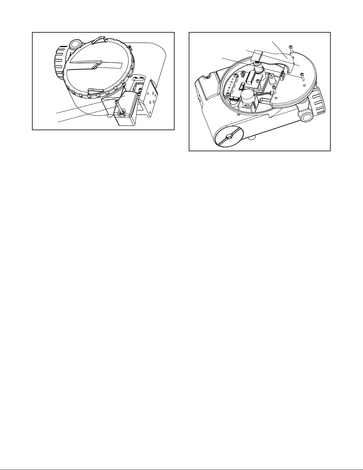
Spool Valve
Cover
Screw
Figure 7: Spool Valve Cover Assembly
Ribbon Cable
Main PCB Assembly
Screws (3)
Regulator
The regulator reduces the pressure of the incoming
supply air to a level that the driver module can use.
Replacing Regulator
1. Make sure valve is bypassed or in a safe condition.
2. Disconnect the power and air supply to the unit.
3. Remove the main cover and unscrew the regulator
from the interface plate, exercising caution not to
damage the collector board (Figure 19).
4. Verify that the O-rings are in place on the base of the
new regulator
5. Replace the regulator by threading into the port on
the interface plate.
6. Check regulating pressure to ensure that it is set at
22 psi.
Internal Coalescing Filter
The internal coalescing filter ensures that supply air is
clean and dry before it gets to the regulator. Because the
air has already been filtered before this point, the element
should not require extended maintenance.
Replacing Input Filter Element (Figure 19)
1. Make sure valve is bypassed or in a safe condition.
2. Disconnect the power and air supply to the unit.
3. Remove the main cover and remove collector board
by disconnecting the wiring and removing three
screws that attach it to the housing. Each cable has
its own unique connector to prevent improper
connections.
4. Remove the four No. 6-32 hex screws from the filter
housing and remove filter housing.
5. Remove the old coalescing filter from the bore in the
interface plate.
Figure 8: Main PCB Assembly
6. Insert new coalescing filter into the bore on interface
plate.
7. Verify that the O-ring is in place in filter housing.
8. Set filter housing over coalescing filter and secure
with four No. 6-32 screws.
9. Replace collector board and reconnect wiring.
Main PCB Assembly
The main PCB assembly contains the circuit boards and
processor that perform the control functions of the
positioner. The boards are conformal-coated with a
protective silicon coating. This module can be easily
replaced if positioner upgrades are desired. None of the
components are user-serviceable. This module is to be
replaced as an entire unit.
Replacing Main PCB Assembly (Figure 8)
1. Make sure valve is bypassed or in a safe condition.
2. Disconnect the power and air supply to the unit.
3. Remove the main cover and disconnect the ribbon
cable from the collector board.
CAUTION: To avoid damaging any components,
exercise caution by gently raising the locking tab
to release the ribbon cable.
4. Remove the PCB assembly by removing the three
No. 6-32 screws and lifting out of housing.
5. Place the new PCB assembly on bosses inside the
positioner housing.
6. Insert three No. 6-32 screws through the boards, with
the nylon washers on the bottom into the threaded
bosses and tighten evenly, using a phillips screwdriver. Do not overtighten.
7. Reconnect the ribbon cable to the collector board.
46-7Flowserve Corporation, Valtek Control Products, Tel. USA 801 489 8611
Page 8
Collector Board
The collector board assembly provides a central routing
for all electronic connections in the positioner, linking the
pressure modulator coil, hall effect sensor and field
inputs to the main electronics. The collector board
assembly also serves as a mounting for the pressure
sensors used on the advanced model of the positioner.
Removing Collector Board (Figure 19)
1. Make sure valve is bypassed or in a safe condition.
2. Disconnect the power and air supply to the unit.
3. Remove the main cover and disconnect the wiring to
the collector board. Each cable has its own unique
connector to prevent mistakes in reconnecting.
4. Remove the three No. 8-32 screws holding the
collector board to the housing.
5. Remove the collector board.
Replacing/Upgrading Collector Board
1. For the advanced collector board (Logix 1x1x),
check that pressures sensors are in place on back
of collector board. For the standard model (Logix
1x0x), make sure the adapter block is securely
fastened to the collector board.
2. Make sure the O-rings are in place in the counterbores
of the pressure ports.
3. Set collector board assembly in place.
4. Insert three No. 8-32 screws through collector boards
into the threaded holes on sensor shelf and standoff.
5. Tighten all three screws.
6. Connect the main ribbon from electronics tray.
7. Reconnect wiring to the collector board.
Field Terminations
The field terminations board provides a connection point
inside the explosion-proof housing for all hookups to the
positioner. While the board is not likely to experience a
failure, it can easily be replaced to upgrade the positioner.
Replacing Field Terminations Board
(Figure 19)
1. Make sure valve is bypassed or in a safe condition.
2. Disconnect the power and air supply to the unit.
3. Remove the main cover and disconnect the field
termination cable from collector board.
4. Remove the field terminations cover and the three
No. 8-32 screws.
5. Remove field terminations board, carefully pulling
wiring through bore.
6. Verify that the O-ring is in place in the counter bore
in the positioner housing.
7. Feed wiring through passageway into main chamber
of housing.
8. Set the circuit board in place and secure with three
No. 8-32 screws.
9. Connect field termination cable to collector board.
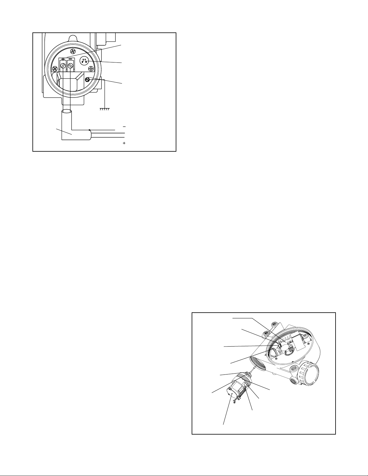
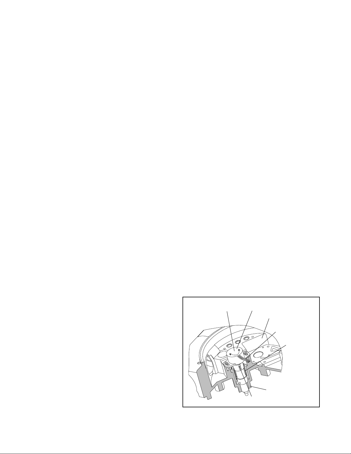
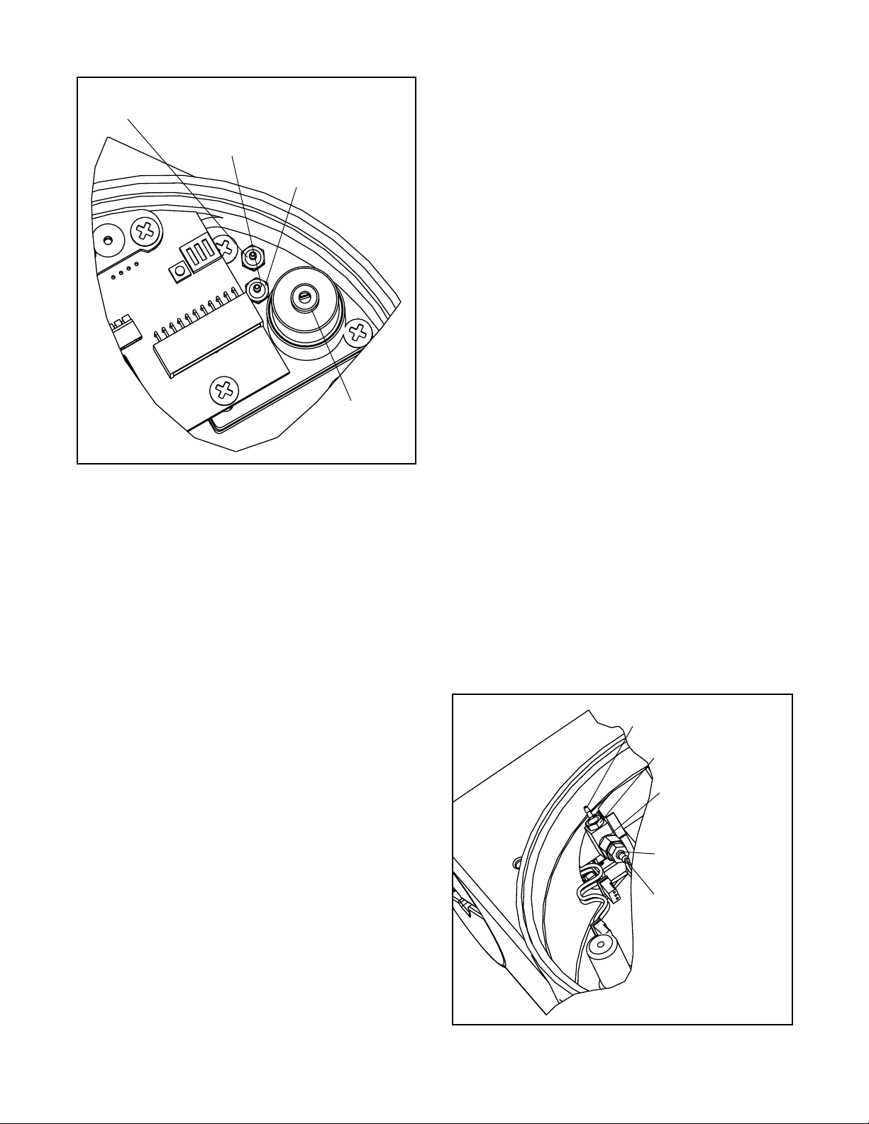
Stem Position Sensor
The position feedback assembly transmits valve position information to the processor by means of a rotary
position sensor that connects to the valve stem through
a feedback linkage. The follower arm is biased against
one side of the slot with a rotary spring to provide
accurate tracking of the pin in the slot. This spring also
automatically moves the position feedback assembly to
its limit in the unlikely event of failure of any component
in the linkage.
Stem Position Sensor Replacement
(Figure 9)
1. Make sure valve is bypassed or in a safe condition.
2. Disconnect the power and air supply to the unit.
3. Remove the main cover and disconnect rotary position sensor wires from collector board.
4. Remove the two screws from the rotary position
sensor, taking care not to lose the washers, and
remove the sensor from the housing.
5. Turn position sensor shaft until the dot on the slot is
aligned with the wires on the pot (Figure 9).
6. Insert the position sensor into the shaft with the
wires pointing toward the main PCB assembly. Turn
position sensor clockwise until the bolting slots align
with the housing screw holes and the wires on the
sensor protrude over the main PCB assembly tray.
7. Carefully center the position sensor on the shaft
bore, insert and tighten the screws.
Do not over
tighten.
8. Route wires along the position sensor and reconnect
to collector board.
Rotate Stem Position
Sensor
slowly
Stem Position Sensor
Housing
Sensor Cable
Feedback
Shaft
Bearing
Stem Position Sensor Dot
Figure 9:
Stem Position Sensor Orientation
46-8 Flowserve Corporation, Valtek Control Products, Tel. USA 801 489 8611
Page 9
LED Indicators
The Logix 1400 digital positioner has three LED indicators that are visible through a window in the main cover.
Only one LED will blink at any given time. Each LED has
a different color to convey basic information about the
positioner status. Green indicates that the positioner is
operating normally. Yellow indicates that a ‘customer
defined limit’ or ‘alert’ has been reached. Red indicates
that an error condition exists. A fieldbus configurator
must be used to determine the specific reason for a
yellow or red LED status.
During stroke and actuator calibration, no LED will blink.
After calibration is complete, the green LED indicates
that the calibration was completed successfully. If the
yellow or red LED blinks after a calibration process, a
warning or error was detected and the configurator must
be used to identify the specific calibration error.
NOTE: If the LED indicator changes from green to yellow
after a calibration process, the user may have set a
warning limit (position alert, cycle counter alert, etc.).
Use a fieldbus configurator to monitor status.
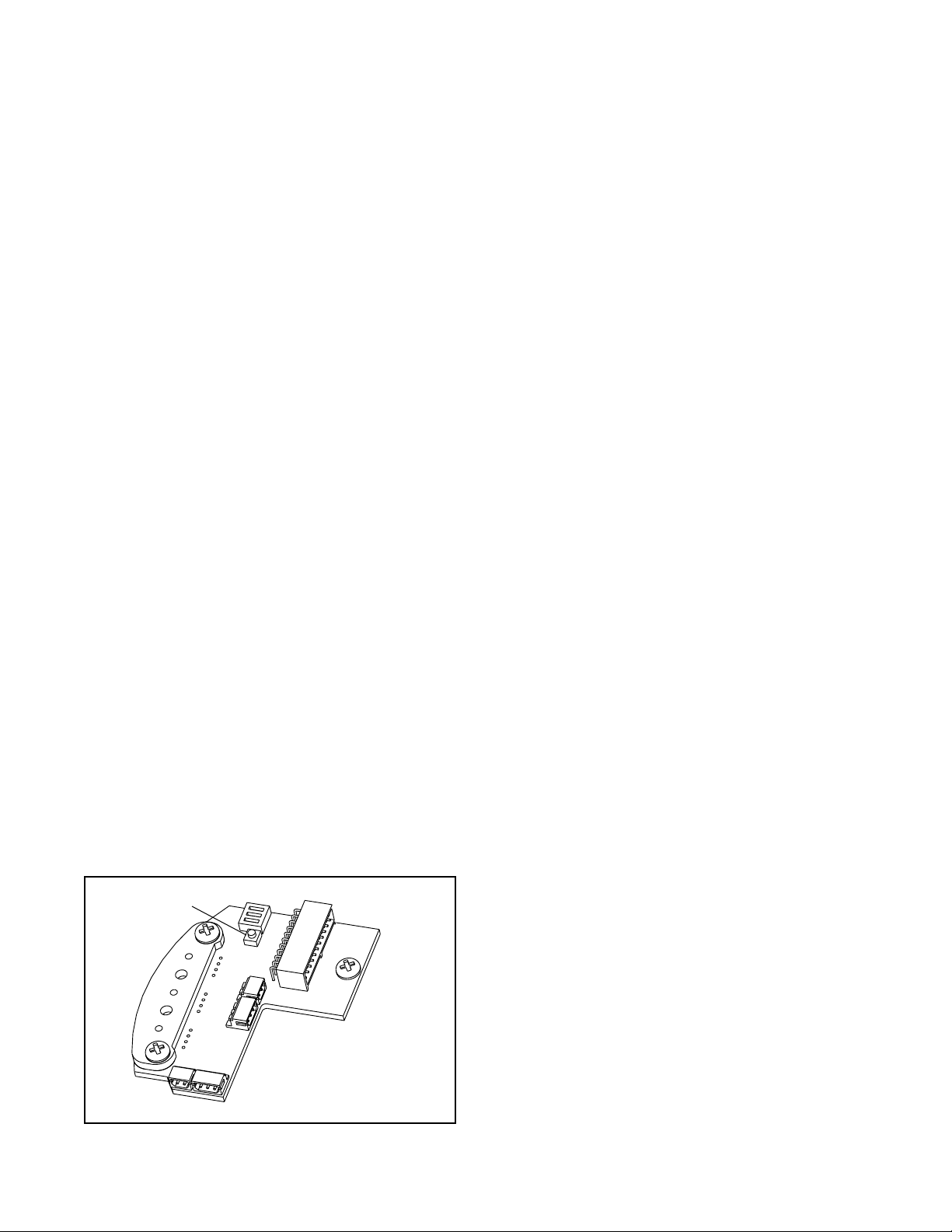
Re-Cal Button
If the fieldbus configurator is not available, Logix 1400
digital positioner has a Re-Cal feature that performs a
stroke calibration and allows basic operation of the positioner.
NOTE:The Re-Cal operation retains all previously configured information. All settings remain unchanged except
stroke calibration parameters. If the device is being
installed for the first time, factory default parameters are
used. The FB Configurator must be used the first time to
configure the Logix 1400 digital positioner. The trans-
ducer block must be out of service for Re-cal to work.
The Re-Cal button is located on the collector board inside
the main housing chamber as shown in Figure 10.
Warning: Accessing this function requires removal
of the main cover. The user must take all necessary
precautions if this operation is performed in explosion-proof areas.
Re-Cal Button
NOTE: DIP switches not
used on Logix 1400
positioner
Figure 10: Re-Cal Button
Make the appropriate configuration settings, using FB
Configurator and CONTROL_FLAGS variable. ATO/ATC
selects air-to-open or air-to-close (this is determined by
the mechanical tubing of the actuator). The Actuator
Style check box allows the user to select linear or rotary
feedback linkage. If
activates custom characterization.
Press Re-Cal button and hold for five seconds. If the button
is released before five seconds have elapsed, no action
will be taken. After five seconds, the positioner will begin
a stroke calibration. Release the Re-Cal button once
calibration has started. The positioner will automatically
stroke the valve. No LED will blink during this process.
Upon completion of calibration:
•A blinking green LED indicates the valve is in control
mode and calibration was successful.
•A blinking yellow LED immediately after a stroke
calibration usually indicates that the valve did not
stroke. Check the air supply and cable connections.
• The red LED will blink if a calibration error occurred.
The cause of a red LED is generally a stem position
linkage/feedback sensor alignment problem. For
linear linkage, the active electrical feedback angle is
65 degrees. For rotary linkage, the active electrical
feedback angle is 95 degrees. The red LED indicates
that the mechanical travel is not centered within the
electrical sensor travel. If a red LED is blinking after
a stroke calibration, loosen the feedback sensor
mounting screws as shown in Figure 9. Turn the stem
position sensor slowly while watching the LED indicators. Try small movements, both clockwise and counterclockwise. If the yellow LED begins to blink, the
feedback sensor has been correctly moved into range.
Tighten the feedback sensor mounting screws and
repeat the Re-Cal procedure. If the LED remains red
even after moving the full length of the sensor slot,
verify the following items:
under the CONTROL_FLAGS parameter ‘Actuator
Style’ (checked is rotary, unchecked is linear), stem
clamp and take-off arm height.
Custom
is selected, the positioner
Rotary
check box setting
NOTE:If the stroke stops in the closed position, the error
occurred when the position sensor/linkage was at closed
position. If the stroke stops in the open position, the error
occurred when position sensor/linkage was at the open
position. No calibration parameters are saved if an error
occurs. If the power to the positioner is removed, the unit
will power-up with the previous configuration parameters.
A successful calibration will save parameters.
If the valve does not stroke after pressing the Re-Cal
button, this may be an indication that the internal regulator pressure and/or the driver module minimum pressure is low. Refer to the following instructions to check
and set the internal regulator and minimum pressure
settings.
Note that the tools and equipment used in the next two
procedures are from indicated vendors.
46-9Flowserve Corporation, Valtek Control Products, Tel. USA 801 489 8611
Page 10
This port is Internal Regulator Output. This
should be tubed to orifice on Driver Module.
Check pressure through
No. 10-32 x
1
/16 Barb fitting
Regulator Pressure
Test Port
Internal
Regulator
Set Screw
Figure 11: Internal Regulator
Checking or Setting Internal Regulator
Pressure
1. Disconnect the air supply from the positioner.
2. Remove the main cover. The regulator pressure set
port is factory plugged with a No. 10-32 hex plug
(Figure 11). Replace hex plug with a No. 10-32 x
1
/16-inch barb fitting.
3. Attach a 0 to 30 psi pressure gauge (with some
1
/16-inch flexible tubing) to the barb fitting shown in
Figure 11.
4. Reconnect the air supply to the positioner and read
the internal regulator pressure on the 0 to 30 gauge
(the internal regulator should be set to 22.0 psi).
Adjust the regulator pressure by turning the set
screw with a small flat screwdriver.
5. Once the regulator pressure is set, remove the air
supply to the positioner, and replace the No. 10-32 x
1
/16-inch barb fitting with the No. 10-32 hex plug.
Checking or Setting the Driver Module
Minimum Pressure
Once the internal regulator pressure is set to 22.0 psi, the
driver module minimum pressure can be checked. To do
this, refer to Figure 12, and proceed as follows:
1. Make sure valve is bypassed or in a safe condition.
2. Disconnect power from the positioner.
3. Remove the main cover and remove the
flexible tubing from the orifice.
1
/16-inch
4. Obtain a No. 10-32 x swivel elbow (Pneumadyne part
No. SFL-10 or equivalent).
5. Remove No. 10-32 x .016 orifice (Figure 4) from the
driver module, and screw in No. 10-32 x swivel elbow.
6. Direct the swivel elbow so the minimum pressure
test port is accessible.
7. Screw a No. 10-32 x
1
/16-inch barb fitting into the test
port, and screw the No. 10-32 x .016 orifice into the
end of the elbow as shown.
8. Connect the tubing from the internal regulator output
port to the orifice.
9. Using some
1
/16-inch flexible tubing, connect a 0 to
30 gauge to the minimum pressure set port.
10. Once the gauge is connected, reapply the positioner
air supply. The minimum pressure should now be
registering on the gauge and must be 3.8 to 4.2 psi.
If the minimum pressure is not correct, use a
9
/64-inch Allen wrench to turn the minimum pressure
set screw located at the bottom of the driver module
(Figure 3) until the pressure is in the range indicated.
Cycle the positioner air supply several times and
recheck the minimum pressure and readjust, if
necessary, to ensure that the pressure has settled
within the range specified.
11. When the pressure is set, remove the air supply.
12. Remove the No. 10-32 x
1
/16-inch barb and orifice from
the swivel elbow and then remove the swivel elbow.
13. Replace the orifice as shown in Figure 4 and
reconnect the
1
/16-inch tubing from the internal regulator output port to the orifice. Reconnect the positioner air supply and power. The positioner should
now be ready to calibrate.
Minimum Pressure
Test Port
No.10-32 x
1
/16-inch
barb
No.10-32 x Swivel
ELL Pneumadyne
Part No. SFL-10
No.10-32 x .016
Orifice
Pressure from
Internal Regulator
to be tubed to this
orifice
Figure 12: Driver Module
46-10 Flowserve Corporation, Valtek Control Products, Tel. USA 801 489 8611
Page 11

Logix 1400 Positioner
Locknut
Washer
Follower
Arm
Nut
Lock Washer
Nut
Follower Pin
Take-off Arm
Bracket Bolts
Bracket
Positioner
Bolts
Nut
Stem Clamp
Bolts
Figure 13: Linear Mark I Control Valve Mounting
Linear Mark I Valve Mounting (Figure 13)
The tools required for the following procedure are:
9
/16-inch open-end wrench
7
/16-inch box wrench
3
/8-inch open-end wrench
1. Remove washer and first nut from follower pin
assembly. Insert pin into the appropriate hole in the
follower arm, based on stroke length. The stroke
lengths are stamped next to their corresponding
holes in the follower arms. Make sure the unthreaded
end of the pin is on the stamped side of the arm.
Reinsert lock washer and tighten nut to complete
follower arm assembly.
2. Slide the double-D slot in the follower arm assembly
over the flats on the position feedback shaft in the
back of the positioner. Make sure the arm is pointing
toward the field terminations side of the positioner.
Slide lock washer over the threads on the shaft and
tighten down the nut.
3. Align the bracket with the three outer mounting holes
on the positioner. Fasten with 1/4-inch bolts.
Metal
Washers
4. Screw mounting bolt into the hole on the yoke
mounting pad nearest the cylinder. Stop when the
bolt is approximately 3/16-inch from being flush with
mounting pad.
5. Slip the large end of the teardrop-shaped mounting
hole in the back of the positioner/bracket assembly
over the mounting bolt. Slide the small end of the
teardrop under the mounting bolt and align the lower
mounting holes.
6. Insert lower mounting bolt and tighten the bolting.
7. Slide the appropriate pin slot on the take-off arm,
based on stroke length, over the follower arm pin.
The appropriate stroke lengths are stamped near
each pin slot.
8. Position the take-off arm mounting slot against the
stem clamp mounting pad and insert take off arm
bolting.
9. Center the take-off arm on the rolling sleeve of the
follower pin.
10. Align take-off arm with top plane of the stem clamp
and tighten bolting.
46-11Flowserve Corporation, Valtek Control Products, Tel. USA 801 489 8611
Page 12

Positioner Bolts 1/4-20 (4)*
Bracket Bolts 5/16-18 (2)
Follower Arm,
Rotary
Lock Washer (2)
Bolt No.10-32
Nut No.10-32
Self Tapping
Screws (2)
Spline Lever
Adapter
Figure 14: Standard Rotary Mounting
Standard Rotary Mounting Procedure
(Figure 14)
The standard rotary mounting applies to valve/actuator
assemblies that do not have mounted volume tanks or
handwheels. The standard mounting uses a linkage
directly coupled to the valve shaft. This linkage is not
affected by misalignment between the positioner and the
actuator.
The tools required for the following procedure are:
two5/16-inch open-end wrenches
3
/16-inch box-end wrench
1
/2-inch end wrench phillips driver
1. Fasten spline lever adapter to splined lever using two
No. 6 x 1/2-inch long self tapping screws.
2. Slide take-off arm assembly onto spline lever adapter
shaft and tighten nut with 5/16-inch end wrenches so
arm is snug on shaft but still able to rotate. This will
Nut No.10-32
Lock Washer
* Located in appropriate
Follower Arm
hole pattern as indicated on
bracket. (25, 50, 100/200)
Logix 1400 Positioner
be tightened after the linkage is correctly oriented.
3. Attach follower arm to positioner feedback shaft
using the star washer and No. 10-32 nut.
4. Using four 1/4-20 x .50 L. bolts and 7/16-inch box
wrench, fasten positioner to universal bracket using
appropriate hole pattern (stamped on bracket).
5. Using a 1/2-inch box wrench and two 5/16 -18 x .50 L.
bolts, attach bracket to actuator transfer case pad,
noting that the take-off arm pin must slide into slot on
follower arm. Leave these bolts slightly loose until
final adjustments are made.
6. Adjust bracket position noting the engagement of the
take-off arm pin and the follower arm slot. The pin
should extend approximately 3/16-inch past follower
arm. When properly adjusted, securely tighten the
bracket bolting.
46-12 Flowserve Corporation, Valtek Control Products, Tel. USA 801 489 8611
Page 13

Orient the Take-off Arm for Final Lock Down
Tube positioner to valve in the following manner:
1. Output 1 port of the manifold to bottom side of actuator.
2. Output 2 port of the manifold to the top side of the
actuator.
3. Connect the fieldbus to the field termination screws
under cover.
4. Connect regulated (70 psi) air supply to appropriate
port in manifold.
5. If setup was successful the green LED will blink and
the valve will be in control mode.
Use the NI Configurator to complete and monitor the
following steps:
1. Start the configurator.
2. Monitor the FVPTB block
3. In the transducer block, variable AD_RAW_FB
number is the digital representation of shaft position.
NOTE: To update the AD_RAW_FB variable, the
‘Enable Diagnostic Variable Access’ selection must
be enabled in TEST_MODE of the transducer block.
4. With supply pressure cut, rotate follower arm in the
same direction the shaft would rotate upon a loss of
supply pressure. When the mechanical stop of follower
arm is reached, tighten bolt on the take-off arm.
NOTE: The nut should be snug enough to hold the
follower arm in place but allow movement when
pushed.
The AD_RAW_FB number should now read 3600 or
500 (± 50).
5. Back the follower arm away from the mechanical
stop, watching the AD_RAW_FB number, until the
number changes 50-150 counts.
6. Tighten the nut on the take-off arm.
socket head bolt on the take-off arm needs to be as
tight as possible. If the take-off arm slips the positioner
will need to be re-calibrated.
7. Recalibrate using the Re-Cal button.
8. Set the FINAL_VALUE to 100. Using a screwdriver
press down on the follower arm’s pin so the pin
touches the other side of the slot. The AD_RAW_FB
number should change about 20 counts and the
valve should move a small amount. If no change in
the AD_RAW_FB number or movement in the valve
occurs repeat steps 4-8 but limit the change in
AD_RAW_FB in step 5 to 30-75 counts.
WARNING: Failure to follow this procedure will
result in positioner and/or linkage damage. Check
air-action and stroke carefully before lockdown
of take-off arm to spline lever adapter.
NOTE: The
Optional Rotary Mounting Procedure
(Figure 15)
The optional rotary mounting applies to valve/actuator
assemblies that are equipped with mounted volume
tanks or handwheels. The optional mounting uses a fourbar linkage coupled to the valve shaft. The following tools
are required:
3
/8-inch box wrench
7
/16-inch box wrench
1
/2-inch box wrench
1. Using a 1/2-inch box end wrench and two 5/16-18 x .50
L. bolts, attach bracket to actuator transfer case
pads. Leave bracket loose to allow for adjustment.
2. Using four 1/4-20 x .50 L. bolts and a 1/16-inch box
wrench, fasten positioner to universal bracket, using
the four-hole pattern that locates the positioner the
farthest from the valve. Rotate positioner 90 degrees
from normal so gauges are facing upward.
3. Attach follower arm to positioner feedback shaft,
using the star washer and No. 10-32 nut.
4. Attach tripper and tripper clamp to shaft, using two
1
/4-20 L. bolts and two 1/4-20 locknuts. Leave tripper
loose on shaft until final adjustment.
5. Thread ball joint linkage end to tripper and tighten
(Thread locking compound such as Loctite is recommended to prevent back threading). Adjust length of
tie rod so follower arm and tripper rotate parallel to
each other (the rod must be cut to the desired
length). Connect other ball joint end to follower arm
using a star washer and a No. 10-32 nut.
6. Tighten bracket and tripper bolting.
7. Check for proper operation, note direction of rotation.
WARNING: Rotating in the wrong direction will
result in serious damage to the positioner and/or
linkage. Check air action and stroke direction
carefully.
Third-party Actuator Mounting
Contact the factory for information on mounting the Logix
1400 digital positioner on actuators not manufactured by
Flowserve.
Troubleshooting the Logix 1400 Digital
Positioner
This section provides troubleshooting information for the
two-wire, FOUNDATION fieldbus communication based, Logix
14xx series digital positioner. In addition, pointers on
operation and configuration will also be covered.
Theory of Operation
Figure 16 shows the basic positioning block diagram for
the Logix 1400 digital positioner.
46-13Flowserve Corporation, Valtek Control Products, Tel. USA 801 489 8611
Page 14

Bolts (2)
Locknuts (2)
Tripper
Tripper Clamp
* Tie Rod must be cut to desired length
*Tie Rod
Nut No. 10-32
Lock Washer
Mounting Bolts
1
/4-20 (4)
Bracket Bolts 5/16-18 (2)
Ball Joint Ends
Follower Arm
Rotate Positioner 90°
Figure 15: Optional Rotary Mounting
NOTE: Variable names in Figure 16 are for internal posi-
tioner use and are not directly accessible via fieldbus.
The Logix 1400 digital positioner receives power from the
two-wire, fieldbus input signal. A digital signal, sent via
fieldbus, is used as the command source.
Zero percent is always defined as the valve closed
position and 100 percent is always defined as the valve
open position.
Next, the command value is passed through a characterization/limits algorithm. The positioner no longer
uses CAMs or other mechanical means to characterize the output of the positioner. This function is done
in software, which allows for in-the-field customer
adjustment. The positioner has two basic modes:
linear
and
custom
characterization. In linear mode, the
command signal is passed straight through to the control
algorithm in a 1:1 transfer. In addition the user-defined
46-14 Flowserve Corporation, Valtek Control Products, Tel. USA 801 489 8611
features, Soft Limits, FINAL_VALUE_CUTOFF_HI,
and FINAL_VALUE_CUTOFF_LO may affect the final
command signal. The actual command being used to
position the stem is called CMD_USED. The
CMD_USED is the actual positioning command after any
characterization or user limits have been evaluated.
The Logix 1400 digital positioner uses a two-stage stem
positioning algorithm. The two stages are comprised of
an inner-loop, spool control and an outer-loop, stem
position control. Referring again to Figure 16, a stem
position sensor provides a measurement of the stem
movement. The FINAL_VALUE command is compared
against the FINAL_VALUE_POSITION. If any deviation
exists, the control algorithm sends a signal to the innerloop control to move the spool, up or down, depending
upon the deviation. The inner-loop then quickly adjusts
the spool position. The actuator pressures change and
Page 15

the stem begins to move. The stem movement reduces
the deviation between control command and stem position. This process continues until the deviation goes to
zero. The control algorithm is both proportional and
integral. This algorithm will be further explained later in
this document.
A more detailed example to explain the control function
follows. The following configuration exists.
• Unit will receive its command from the FB.
• Custom characterization is disabled (therefore characterization is linear).
• Soft limits or FINAL_VALUE_CUTOFF are disabled.
• Valve has zero deviation with a present input command of 50 percent.
Actuator is tubed Air-to-Open
Given these conditions, 50 percent represents a command of 50 percent. Custom characterization is disabled
so the command is passed 1:1 to the CMD_USED. Since
zero deviation exists, the stem position is also at 50
percent. With the stem at the desired position, the spool
valve will be at a position in which no air flow is allowed
to either side of the actuator. This is commonly called the
nullorbalanced
mand from 50 percent to 75 percent. The positioner sees
this as a FINAL_VALUE command of 75 percent. With
linear characterization, the CMD_USED becomes 75
percent. Deviation is the difference between the control
command (CMD_USED) and Stem Position: Deviation =
75 percent - 50 percent = +25 percent, where 50 percent
is the present stem position. With positive deviation, the
control algorithm sends a signal to move the spool up
from its present position. As the spool moves up, the
supply air is applied to the bottom of the actuator and air
is exhausted from the top of the actuator. This new
pressure differential causes the stem to start moving
towards the desired position of 75 percent. As the stem
moves, the deviation begins to decrease. The control
algorithm begins to reduce the spool opening. This
process continues until the deviation goes to zero. At
this point, the spool will be back in its
position. Stem movement will stop. Desired stem position has now been achieved.
One important parameter should now be discussed point:
Inner-loop offset. A number called inner-loop offset
(IL_OFFSET) is added to the output of the control
algorithm. (Refer to Figure 16.) For the spool to remain in
its
null
or
output a non-zero spool command. This is the purpose of
the inner-loop offset. The value of this number is equivalent to the signal that must be sent to spool position
control to bring it to a
deviation. This parameter is important for proper control
and will be discussed further in the
section.
spool position. Now, change the com-
null
balanced
position, the control algorithm must
null
position with zero stem
Control and Tuning
or
balanced
Mounting and Installation
Electrical Wiring
Verify polarity when making field termination connection.
With a fieldbus power supply connected, verify that an
LED is blinking to determine if the electronics are
running. Only one LED will blink at any given time.
Compatibility with DCSs using 24VDC
FB specifies a 9-32V operation range. A fieldbus compatible power supply with terminators should be used to
power a Logix 14xx digital positioner with a DCS using
9 - 32 VDC.
Reverse polarity protection
The Logix 14xx digital positioner is reverse polarity
protected. Inadvertent reversing of the voltage supply
across the Logix 1400 digital positioner should not
damage the device, if current is limited.
Air Action
Air-to-open and air-to-close are determined by the actuator tubing, not the software. When air action selection is
made during configuration, the selection is telling the
control which way the actuator is tubed. Verify that tubing
is correct prior to a stroke calibration. The top output port
on the positioner is called
the increase open side of the actuator. That is, for an airto-open actuator,
actuator.
output 1
output 1
should go to the bottom of the
. It should be tubed to
Linear vs. Rotary
The positioner has two configuration settings: Linear and
rotary. To achieve better resolution, stem position sensor gains are adjusted based on the angle of rotation of
the linkage. The linear setting allows for linkage rotation
up to 65 degrees. The rotary setting allows for linkage
rotation up to 95 degrees. These settings only determine
the angle of sensor rotation and do not affect control
parameters. If a positioner is set to linear linkage and a
red LED blinks after calibration, the most common cause
is that the sensor movement was greater than 65 degrees. This can occur if the roller pin was placed in the
wrong hole on the follower arm or the stem clamp is
placed too high. The take-off arm should always be level
with the stem clamp on linear mountings.
The Logix 14xx positioner has an electrical measurement range of 95 degrees. That is, the electronics will
sense stem position over a 100 degrees range of travel
of the follower arm. On a rotary valve, the typical rotation
is 90 degrees. When installing a Logix 14xx positioner on
a rotary valve, it is important that the 90 degrees valve
rotation is centered within the 95 degrees electrical
range. If mechanical movement falls outside the electrical measurement range, the positioner can have a deadband at one end of travel in which valve movement
cannot be sensed.
46-15Flowserve Corporation, Valtek Control Products, Tel. USA 801 489 8611
Page 16

Centering the rotary linkage
To determine whether the rotary linkage is centered in the
100 degrees range move the valve to the fully closed
position. The slot in the take-off arm has enough clearance around the roller pin to move the follower arm
slightly. At this position, move the follower arm within the
slot clearance. If the valve does not respond, linkage
adjustment is necessary. Repeat this test at the fully
open position.
To adjust the stem position linkage, use the AD_RAW_FB
variable. With the valve in its mechanical fail position
(i.e. no pressure applied), slightly move the follower arm
while watching the A/D feedback. If the number does not
change, the arm is not centered in the electrical range.
(The number will bounce 1 or 2 counts due to noise at a
fixed position and should not be considered a change, it
should move greater than 10 to 20 counts if the linkage
is centered correctly). Rotate the take-off arm, if necessary, to bring the linkage in range. This procedure is only
necessary on a rotary mounting. For linear mountings,
the red LED will blink if you exceed 65 degrees travel.
Refer to the
stroke calibration errors.
To view the feedback variable use the FB configurator of
view the AD_RAW_FB in the transducer function block.
NOTE:To update the AD_RAW_FB variable, the ‘Enable
Diagnostic Variable Access’ selection must be enabled in
TEST_MODE of the transducer block.
Calibration
section for further information on
Calibration
Re-Cal
Re-Cal is a method by which the valve can be stroke
calibrated without using the fieldbus configurator.
NOTE:The transducer function block must be in OOS (out
of service) mode for the Re-Cal button to be operational.
Re-Cal only affects position calibration. Any previous
configuration or stored information is not affected.
Position 0% Calibration Flag in
CALIBRATE_FLAGS
Position 100% Calibration Flag in
CALIBRATE_FLAGS
During stroke calibration, the Logix 1400 digital positioner checks to see if the linkage is placing the stem
position sensor in range. If the valve stroke causes stem
position measurement to go out of range in the open
position, a
valve stem will stop in the open position and the red LED
will blink. Linkage must be adjusted to bring the sensor
in range.
range, the LEDs can be used as an adjustment guide. The
LED will change from a red to yellow when the linkage is
brought into range.
Position 100% Flag
Special LED indication: If the linkage is out of
will be generated. The
Position Span Flag in
CALIBRATE_FLAGS
Position span is a check during stroke calibration to
verify that the valve stem moved. The algorithm waits to
see if no movement is detected when the valve is
automatically stroked open. Anything which could prevent the valve from stroking will generate a
error (no supply pressure, malfunctioning spool valve).
Position Span
Control and Tuning
Setting P + I Parameters
Using the configurator, you can set individual tuning
parameters. A few key points are mentioned below. (See
Figure 17.)
GAIN_UPPER, GAIN_LOWER, and GAIN_MULT: These
three parameters are related by the following formula.
Proportional Gain =
Maximum Gain - Ideviation| x Gain Multiplier
If Proportional Gain < Minimum Gain,
then Proportional Gain = Minimum Gain
This algorithm allows for quicker response to smaller
steps yet stable control for large steps. Setting the gain
multiplier to zero and max gain = min gain results in a
typical fixed proportional gain.
The higher the gain multiplier, the larger the required
deviation before the gain increases. Default values
upon initiating a RESET to factory defaults (under
During stroke calibration, the Logix 1400 digital positioner checks to see if the linkage is placing the stem
position sensor in range. If the valve stroke causes stem
position measurement to go out of range in the closed
position, a
stem will stop in the closed position and the red LED will
blink. Linkage must be adjusted to bring the sensor in
range.
range, the LEDs can be used as an adjustment guide. The
LED will change from a red to yellow when the linkage is
brought into range.
46-16 Flowserve Corporation, Valtek Control Products, Tel. USA 801 489 8611
Position 0% Flag
Special LED indication: If the linkage is out of
will be generated. The valve
Figure 16: Gain Effect Diagram
Page 17

Air Supply
Tubed ATO
Control
Algorithm
P
max
P
min
G
mult
(GAIN_MULTI)
Integration Summer
Inner Loop Offset
XDAO
Linear Mode
Characterization
Soft Limits
MPC
Control
Command
(CMD_USED)
+
Deviation
Position
Figure 17: Logix 1400 Digital Positioner Block Diagram
LOAD_EE_DEFAULTS) are maximum gain = 2.0, minimum gain= 1.0, and gain multiplier= 0.05. These values
will allow stable control on all Valtek control product
actuator sizes.
Integral Gain (IGAIN): The integral gain is primarily for
deviations due to temperature drift within the inner loop
spool control. The factory default value is 10. Although
higher numbers can speed the time it takes to reach zero
deviation, it can add overshoot if too large. It is recommended that maximum and minimum gains be adjusted
while leaving integral gain fixed at 10. Integration is
disabled below a stem position of 3 percent and above a
stem position of 97 percent. This is to prevent integration
windup from calibration shifts due to lower pressure or a
damaged seat which may prevent fully closing the valve.
Integration Summer: The integral summer within the
Logix 1400 digital positioner is clamped at +20 percent
and -20 percent. If the integration summer is fixed at +20
percent or -20 percent, it usually indicates a control
problem. Some reasons for a clamped integration summer are listed below:
• Stroke calibration incorrect.
• Any failure which prevents stem position movement:
stuck spool, handwheel override, low pressure.
• Incorrect inner loop offset.
• Loss of air supply on a fail in place actuator.
Writing a zero to integral gain (IGAIN) will clear the
integral summer. The integral gain can then be returned
to its original value.
Inner loop offset (IL_OFFSET): Three control numbers
are summed to drive the inner loop spool position control:
proportional gain, integral summer, and inner-loop offset.
Inner-loop offset is the parameter which holds the spool
in the ‘null’ or ‘balance’ position with a control deviation
of zero. This value is written by the positioner during
Sensor
Modulator
Coil Current
Inner Loop
Spool Control
Stem
Position
Sensor
(GAIN_UPPER)
(GAIN_LOWER)
(IL_OFFSET)
(HALL_SENSOR)
D/A Output
Percentage
Inner-Loop
Hall Sensor
Output
stroke calibration and is a function of the mechanical and
electrical spool sensing tolerances. However, if it becomes necessary to replace the driver module assembly
or the software RESET calibration constants has been
performed, it may be necessary to adjust this value. The
method below should be used to adjust inner-loop offset.
Or simply perform a new stroke calibration.
From the fieldbus configurator:
• Send a 50 percent command.
• Set integral to zero.
• Locate the DAC_PERCENT
• Write this percentage value to IL_OFFSET
• Write original value to Integral
These tuning sets can be used to obtain initial values for
Flowserve products and comparable actuator sizes. The
user may need to adjust this tuning to achieve optimal
performance for a particular application.
Table I: Factory Tuning Sets
.gfM
ketlaVA_yrotcaFV0.10.250.00152
remmaK84repoorT4.05.050.05213
xamotuA1R3.05.050.0015ot3
gninuT
teS
B_yrotcaFV0.15.250.00105
C_yrotcaFV0.20.350.001001
D_yrotcaFV0.40.550.001002
E_yrotcaFV0.40.750.001003
84repoorT4.05.050.05213
94repoorT0.30.450.0015.77
94repoorT0.30.450.0015.77
2R0.15.150.00121ot9
3R3.10.250.00191ot61
4R0.25.250.00173ot72
5R5.26.350.00157ot84
6R0.40.550.001901
_NIAG
_NIAG
_NIAG
REWOL
REPPU
niagl
TLUM
elbarapmoC
).ni.qs(eziS
46-17Flowserve Corporation, Valtek Control Products, Tel. USA 801 489 8611
Page 18

Spool Valve
The spool valve is a four-way directional valve with
precision features to provide optimal control and low air
consumption. To help prevent spool valve malfunction,
the positioner supply air must conform to ISA Standard
S7.3 (a dew point at least 18 degrees below ambient
temperature, particle size below 1 microns, oil content
not to exceed 1 part per million). Flowserve’s standard
coalescing filter is highly recommended to help meet
these requirements.
Small particles, oil that has varnished, corrosion, ice,
burrs and extreme wear could cause the spool valve to
act abnormally. If the spool valve is suspected of
sticking, it can be inspected by performing the following.
1. Make sure the valve is bypassed or in a safe condition.
2. Disconnect the power and air supply to the unit.
3. Remove the spool valve cover by removing the
screw and sliding the cover assembly backwards
until the tab is clear of the slot.
4. Inspect the coalescing filter element in the spool
valve cover for signs of oil, water and debris that may
have come from the air supply. A clean filter is white.
5. Remove the two phillips-head screws holding the
spool valve to the housing. Inspect the free movement of the spool by carefully sliding the block up
and down on the spool about 1/4 inch. The block
should slide on the spool with no resistance. Carefully remove the block ensuring it is removed concentric with the spool.
6. Inspect the block and spool for oil, water, debris and
wear. If oil, water and/or debris are found, the spool
and block can be cleaned with a non-residue cleaner,
lint free cloth and soft bristle brush. If wear is found,
replace the driver module assembly as instructed in
this document.
7. Before reassembly, verify that the three O-rings are
in the counter-bores on the machined platform where
the spool valve block is to be placed.
8. Carefully slide the block over the spool, using the
machined surface of the housing base as a register.
Slide the block toward the driver module until the two
retaining holes line up with the threaded holes in the
base. If resistance is still encountered re-clean both
parts or replace the driver module assembly. Refer
to the
Spare Part Kits
section.
Alarms
The Logix 1400 digital positioner has several internal
alarms which monitor electronics operation. An internal
alarm causes the red LED to blink. Alarms differ from
alerts because the action of the positioner may be erratic
during the alarm conditions. Alert warns operations that
a predefined, user configured, condition has occurred
that may require service in the near future. Alarms cause
the red LED to blink, while alerts cause the yellow LED
to blink. Refer to the FOUNDATION fieldbus documentation
for the handling of FB alerts and alarms.
12-bit A/D Reference Alarm
The Logix 1400 digital positioner utilizes a 12-bit analogto-digital converter to acquire stem position readings. If
the precision reference used by the A/D drifts outside
rated tolerances, the 12-bit A/D reference alarm will
become active. A reference error will cause change in
calibration and control readings. If a continuous 12-bit
A/D reference alarm exists, the main PCB assembly
must be replaced. Refer to the
Spare Part Kits
section.
1.23 V Reference Alarm
The 1.23 V reference is used by the inner-loop spool
position control. If it drifts outside normal tolerances, the
1.23 V reference alarm will become active. If a continuous 1.23 V reference alarm exists, the main PCB
assembly must be replaced. Refer to the
section.
Spare Part Kits
12-bit D/A Alarm
The Logix 1400 digital positioner utilizes a 12-bit digitalto-analog converter to send a control signal from the
microcontroller to the inner loop spool positioning circuit.
The output of the D/A converter is independently measured to verify correct operation. A 12-bit D/A alarm
indicates that the D/A may be malfunctioning. If a
continuous 12-bit D/A Alarm exists, the main PCB
assembly must be replaced. Refer to the
section.
Spare Part Kits
Temperature Alarm
The main PCB assembly contains an ambient temperature sensor. If the ambient temperature readings goes
outside the operating range, -40° F to +185° F (-40° C to
+85° C), the temperature alarm will become active. The
red LED will also blink. If this alarm is present and the
ambient temperature reading is incorrect, the main PCB
assembly must be replaced. Refer to the
section.
Spare Part Kits
Hall Sensor Alarm
The Logix 1400 digital positioner uses an inner-loop,
spool-positioning stage. A hall sensor is used for spool
control. If the electronics senses a problem with the
sensor, the hall sensor alarm will activate. Some common reasons for a hall sensor alarm are loose or missing
cable connection to the collector board assembly or a
broken wire. In the event that the actual hall sensor is
defective, the driver module assembly must be replaced.
Refer to the
Spare Part Kits
section.
46-18 Flowserve Corporation, Valtek Control Products, Tel. USA 801 489 8611
Page 19

Modulator Current Alarm
The pressure modulator is an electro-pnuematic device
which takes a current signal from the electronics control
and generates a pressure which moves the spool. The
Logix 1400 digital positioner is a FB powered device
which must run on very low power. During operation, the
pressure modulator current is monitored. If the current
draw exceeds 0.9mA under normal control, the modulator current alarm will become active and the red LED will
blink. Sometimes, the current level may be right at the
threshold of 0.9mA causing the LED to alternate between
red and green. Listed below are some reasons for a
modulator current alarm. The magnitude of modulator
coil current can be viewed from the configurator.
• Modulator minimum pressure too low
• Clogged or restricted orifice
• Bad or missing cable connection to collector board
assembly
• Stuck or sticky spool
• Internal air leaks: tubing, orifice gasket, pressure
modulator
EEPROM Checksum Alarm
Configuration data is stored in EEPROM. When power is
lost, configuration information is retrieved from EEPROM
and operation resumes. A check is done by the microcontroller after a power-up to make sure data saved in
EEPROM has not been corrupted. The checksum is a
number which is calculated based on configuration data.
It is also saved in EEPROM every time data is stored. If
after a power-up, this number does not match the data in
memory, an EEPROM checksum alarm is generated and
the red LED will blink. If this occurs, try powering the
Logix 1400 digital positioner off and then back on. If the
error does not clear, try saving configuration data again
using FB Configurator. If previous configuration has not
been saved, you must reset the device and re-configure.
If these steps still do not clear the error, the main PCB
assembly must be replaced. Refer to the
section.
Spare Part Kits
Pressure Alarms
Note: Pressure alarms are only available on models with
advanced diagnostics (Logix 141x).
Advanced diagnostic models add ouput port 1, output port
2 and supply pressure sensors. These sensor readings
and alarms are only accessible from the communicator
when the configuration has been set to advanced.
Loss of Pressure: The loss of pressure alarm becomes
active when the supply pressure is near the minimum
positioner operating pressure of 30 psig. If the LEDs
alternate between red and green, the supply pressure
may be at the limit threshold. This alarm is meant to alert
the user to low supply pressure as well as complete loss
of pressure.
Output Port 1 Sensor, Output Port 2 Sensor, Supply
Sensor: Each sensor is checked during actuator calibra-
tion. If a calibration reading appears to be out of range,
the appropriate alarm will become active. The pressure
sensors are located on the collector board assembly.
Alerts
FINAL_VALUE_CUTOFF
The FINAL_VALUE_CUTOFF or tight shutoff feature
of the Logix 1400 digital positioner allows the user to
control the level at which the command signal causes
full actuator saturation in the closed or open position.
This feature can be used to guarantee actuator saturation in the closed or open position or prevent throttling
around the seat at small command signal levels. To
enable, use configuration to apply the desired
FINAL_VALUE_CUTOFF threshold.
Note: The positioner automatically adds a 1 percent
hysteresis value to the FINAL_VALUE_CUTOFF_LO
setting to prevent jumping in and out of saturation when
the command is close to the setting.
Effects of FINAL_VALUE_CUTOFF on Operation
With the FINAL_VALUE_CUTOFF_LO set at 5 percent
the positioner will operate as follows:
Assume that the present command signal is at 50
percent. If the command signal is decreased, the positioner will follow the command until it reaches 5 percent.
At 5 percent, full actuator saturation will occur. The
actuator will maintain full saturation below 5 percent
command signal. Now, as the command increases, the
positioner will remain saturated until the command
reaches 6 percent (remember the 1 percent hysteresis
value added by the positioner). At this point, the stem
position will follow the command signal.
If the FINAL_VALUE_CUTOFF_LO is set to 3 percent
but the valve will not go below 10 percent,
SOFTSTOP_LOW may be enabled. The lower soft
limit must be less than or equal to 0 percent in order
for the FINAL_VALUE_CUTOFF_LO to become active. If soft stops are active (ie: SOFTSTOP_LOW =
0 or SOFTSTOP_HIGH = 100) FINAL_VALUE_CUTOFF
is disabled.
Soft Limits
Unlike position alerts, soft limits prevent the stem position from going below or above the configured limits. If
the command signal is trying to drive the position past
one of the limits, the yellow LED will blink but the stem
position will remain at the set limit.
Travel Accumulator
The travel accumulator is equivalent to a car odometer
and sums the total valve movement. Using the user
defined stroke length and travel dead-band, the Logix
46-19Flowserve Corporation, Valtek Control Products, Tel. USA 801 489 8611
Page 20

1400 digital positioner keeps a running total of valve
movement. When the positioner first powers up, high and
low dead-band limits are calculated around the present
position. When the stem position exceeds the travel
dead-band, the movement from the center of the deadband region to the new position is calculated and added
to the travel accumulator. From this new position, deadband high and low limits are again calculated.
Example: The Logix 1400 digital positioner has a default
dead-band configuration of 20 percent. The valve has a
4 inch linear stroke. When the valve first powers up, the
command signal is 50 percent. The unit will calculate a
high travel threshold of 70 percent (50 percent present
position plus 20 percent dead-band) and a low travel
threshold of 30 percent (50 percent present position
minus 20 percent dead-band). As long as the stem
position remains greater than 30 percent and less than 70
percent, no additions are made to the travel accumulator.
Now, assume the stem position moves to 80 percent
which is outside the present dead-band. The Logix 1400
digital positioner calculates the stem movement and
adds this number to the travel accumulator.
80 percent (present position) - 50 percent (previous) =
30 percent movement x 4-inch stroke = 1.2 inches
So, 1.2 inches is added to the travel accumulator. New
dead-band thresholds of 100 percent (80 percent present
position plus 20 percent dead-band) and 60 percent (80
percent present position minus 20 percent dead-band)
are calculated. This process continues as the stem
position moves throughout its stroke range.
Cycle Counter
The cycle counter is another means of monitoring valve
travel. Unlike the travel accumulator, the stem position
must do two things to count as a cycle: exceed the cycle
counter dead-band and change direction. A cycle counter
limit can also be written into the positioner. If this limit is
exceeded, the yellow LED will blink.
Position Deviation
If the stem position differs from the control command by
a certain amount for a given length of time, the yellow
LED will blink to signify excess deviation. The trip point
and settling times are set from the transducer function
block.
Advanced Features
Note: These features are contained in the transducer
function block.
Standard vs. Advanced Diagnostics
Advanced diagnostics models add top, bottom, and
supply pressure sensors. This allows for more diagnostic calculations such as loss of pressure, advanced
signatures, and troubleshooting.
Temperature and Pressure Units
The desired temperature and pressure units can be set
during configuration. Once set, all readings will be displayed in the desired units.
Stroke Length
Stroke length is used by the travel accumulator. When
the stroke length and units are set, the length is used to
determine the total travel accumulated. The travel accumulator will have the units associated with stroke.
Example: Stroke length is set to four inches. If the valve
is moved from 0 percent to 100 percent, four inches will
be added to the travel accumulator. The travel accumulator units will be inches. If Stroke length is 90 degrees
for a rotary, the travel accumulator will now have units of
degree. A 0 percent to 100 percent stroke will add 90 to
the travel accumulator.
Note: Stroke length is for information only and is not used
during calibration.
Custom Characterization
Custom characterization can be thought of as a ‘soft
CAM.’ The user can choose between a linear, equal
percent, quick-open, or custom user-defined characterization curve using 21-points. The control will linearly
interpolate between points. Points do not have to be
equally spaced in order to allow more definition at critical
curve areas.
The Logix 1400 digital positioner has two modes: linear
and custom characterization. Linear is a straight 1:1
mapping of command to control command. It does not
use the 21-point curve definition. When custom characterization is
Linear mode. If custom characterization is
Logix 1400 digital positioner uses a 21-point defined
curve.
The Logix 1400 digital positioner comes with a factorydefault equal-percent and quick-open curve as shown in
Figure 18.
disabled
, the positioner is automatically in
enabled
, the
Stroke Characterization
In addition to two pre-defined and embedded characterization curves, the Logix 1400 digital positioner has a 21point custom stroke characterization feature. This allows the user to define a unique set of operating parameters customizable to his process conditions.
Characterization Procedure
The following procedure outlines the basic way setting up
a custom stroke characterization takes place.
1. Verify the process is in a safe condition and that the
valve may be taken out of service.
2. Put the Transducer block MODE_BLK in OOS (Out
Of Service)
46-20 Flowserve Corporation, Valtek Control Products, Tel. USA 801 489 8611
Page 21

100
90
80
70
60
50
40
30
CMD_USED (% FS)
20
10
0
0 20 40 60 80 100
FINAL_VALUE (% FS)
Quick Open
Equal Percent
Linear
Figure 18: Characterization Curve
3. Make sure that
Curve
, nor
lected in CONTROL_FLAGS.
4. Enter the values for CURVEX and CURVEY to
define the desired response. Care must be taken to
assure that each CURVEX value has the correct
corresponding CURVEY value. The user may choose
any number in the range to define the curve. The 21
CURVEX points do not need to be evenly spaced, if
so desired. However, the CURVEX values must be
in ascending (or equal) order. The CURVEY points
may be any value in the range, ascending or descending. The response is a linear interpolation, or
straight-line, response between points. All 21-points
must be defined. (i.e. If only five point sets were
needed to define the desired operation, the remaining 16 points would need to be set to 110.).
5. Write changes to the Logix 1400 digital positioner.
6. Activate the custom curve by selecting
Characterization Active
Make sure that neither
Equal Percent Curve
7. Write the changes to the Logix 1400 digital positioner.
8. Verify the proper operation of the stroke response by
incrementally writing values to FINAL_VALUE. (The
AO block must also be OOS first.) CMD_USED,
FINAL_POSITION_VALUE, and the valve response
should track the desired curve.
9. Return the valve to service by returning both the AO
and FVPTB blocks to auto mode.
Quick Opening Curve,Equal Percent
Custom Characterization Active
in CONTROL_FLAGS.
Quick Opening Curve
has been selected.
are se-
Custom
NOTE:
nor
Characterization Retention
Once a custom curve has been loaded into the Logix
1400 digital positioner’s memory it is retained in the
EPROM until it is either edited or replaced. Turning
Table II: Logix 1400 Digital Positioner
Characteristic Curves
_LANIF
EULAV
)SF%(
XEVRUC
00.000.00
58.8100.15
016.7300.201
514.6500.351
020.4700.402
523.4842.552
030.0974.603
530.2920.853
044.3975.904
542.4968.1154
058.4951.4105
555.5945.7155
060.6939.0206
565.6949.5256
070.7959.0307
575.7963.8357
080.8977.5408
585.8966.5558
090.9986.7609
595.9913.2859
001001001001
nepOkciuQ
Custom Characterization Active
lauqE
tnecreP
on or off now selects
between a linear response (off), or the new custom curve
(on). If either of the other two factory curves is selected
it will overwrite the custom curve in RAM only. The
custom user-defined curve will automatically be activated again when the factory curve is deselected.
YEVRUC)SF%(DESU_DMC
raeniL
Initiating a Valve Signature
A feature of the Logix 1400 positioner is the ability to
capture and store a valve diagnostic signature. A signature is the collected data response of the valve to a
predefined set of operating conditions. This stored data
can later be uploaded to the host system for analysis of
potential problems. By comparing a baseline signature,
when the valve is new, to subsequent signatures at later
times, a rate of change can be tracked which can help
predict possible faults in the valve before they happen.
This is called ‘predictive maintenance’. It is important to
note that the purpose of the positioner is to act as the
data acquisition device for the signature. Analysis of the
data is not done on the device, but in the supervisory
system.
Note: Signature data is lost if the positioner is reset or if
the power is cycled.
46-21Flowserve Corporation, Valtek Control Products, Tel. USA 801 489 8611
Page 22

System Preparation
WARNING: By definition, the collection of the signature requires the unmanaged operation of the positioner. Therefore, the process must be in a safe
operating mode where unexpected movement of the
valve will not cause a hazardous condition.
Before a valve signature can be run, the Transducer
Block must out of service (OOS).
Signature Procedure
The following steps are an example of how to initiate a
ramp signature capture. (Refer to Table IV.)
1. Make sure the process is in safe condition and notify
the control room that the valve will temporarily be
taken off-line.
2. Verify preparedness to proceed.
3. Put the Transducer block MODE_BLK OOS
4. Set SIG_START to desired value.
5. Set SIG_STOP to desired value.
6. Set SAMPLE_TIME to desired value (typically 0.1).
7. In SIG_FLAGS, select; STEP_RAMP,
PRESS_MEAS.
8. Write values to the Logix 1400 digital positioner.
9. Set RAMP_RATE to desired value (typically 100).
10. Write value to the Logix 1400 digital positioner.
11. In SIG_FLAGS, select BEGIN_SIG.
12. Write value to the Logix 1400 digital positioner.
13. The valve will stroke to the beginning position, as
defined by SIG_START ,and will begin ramping to
the desired ending position, as defined by SIG_STOP.
Notice that SIG_COUNTER will increment while this
takes place. (Typically approximately 670 data sets
will be collected with the above settings and full
stroke of the valve. Exact numbers will vary.)
14. SIG_FLAGS indicates SIG COMPLETE.
15. Return the MODE_BLK to auto.
16. Notify control room the valve is back on-line. The
stored signature will remain in the Logix 1400 digital
positioner RAM until the either the unit is powered
down, or another signature is taken which overwrites
the previous one.
STEP SIGNATURE
If a step signature was desired, simply do not select
STEP_RAMP in SIG_FLAGS, and then set the
STEP_TIME prior to selecting BEGIN_SIG.
Collection of Stored Signature
The collection of the stored signature is accomplished by
the host system. It is not part of the device. See host
system programming.
A simple utility using National Instruments NI-FBUS is
available from Flowserve for retrieving a signature file.
The retrieved file is stored in a text format that can be
imported into other programs for plotting and analysis.
Contact Flowserve for more details.
Table III: Transducer Block Characterization Parameters
retemaraPnoitpircseDgninaeM--eulaVstnemmoC
KLB_EDOMfoedomgnitarepoehT
kcolbrecudsnarteht
_LORTNOC
SGALF
XEVRUCyarraeulavXciremuN
YEVRUCyarraeulavYciremuN
*NOTE: Must not be selected if a custom curve is to be created or edited.
hcihwseulavetyB
renoitisoptceles
serutaefnoitarepo
.tniopmotsucrof
)stniopyarra12x1(
.tniopmotsucrof
)stniopyarra12x1(
46-22 Flowserve Corporation, Valtek Control Products, Tel. USA 801 489 8611
:sedoMdettimreP
)edomtegrat(otuA-otuA
ecivreSfotuO-SOO
*evruCgninepOkciuQ-1
*evruCtnecrePlauqE-2
epyTrotautcA-3
ledoMdecnavdA-4
niaGrotautcAyratoR-5
evitcAnoitaziretcarahCmotsuC-6
DBTnoitisoPliaF-7
noitcAriA-8
ekortsmotsucrofeulavsixa-X
.tniopnoitaziretcarahc
011ot01-egnaR
ekortsmotsucrofeulavsixa-Y
.tniopnoitaziretcarahc
011ot01-egnaR
.evruc
.raeniL
degnahcrodetide
.evrucmotsucsa
fotuoebtsumkcolbrecudsnartehT
ebnacnoitaziretcarahcerofebecivres
motsucsaevrucOQdenifedyrotcafsdaoL
evructnecreplauqedenifedyrotcafsdaoL
siesnopser,ffOfI.evrucmotsucsetavitcA
gnidnopserrochtiweulav-XhcaeriaP
seulaV.tniopderisedehtenifedoteulav-Y
.redro)lauqero(gnidnecsaniebtsum
Page 23

GLOSSARY
A/D: Also called ADC. Analog-to-digital converter. An
A/D converts an analog signal into an integer count.
This integer count is then used by the microcontroller
to process sensor information such as position,
pressure, and temperature.
D/A: Also called DAC. Digital-to-analog converter. A
D/A converts an integer count into an analog output
signal. The D/A is used to take a number from the
microcontroller and command an external device such
as a pressure modulator.
EEPROM (Electrically Erasable Programmable Read
Only Memory): A device which retains data even when
power is lost. Electrically erasable means that data
can be changed. EEPROM have a limited number of
times data can be rewritten (typically 100,000 to
1,000,000 writes).
Micro-controller: In addition to an integral CPU
(microprocessor), the micro-controller has built in
memory and I/O functions such as A/D and D/A.
Microprocessor: Semiconductor device capable of
performing calculations, data transfer, and logic
decisions. Also referred to as CPU (Central Processing Unit).
Protocol: A set of rules governing how communications messages are sent and received.
Resolution: Resolution is a number which indicates
the smallest measurement which can be made. You
will often see analog-to-digital (A/D) converters
referred to as a 10-bit A/D or a 12-bit A/D. 10-bit and
12-bit are terms which indicate the total number of
integer counts which can be used to measure a
sensor or other input. To determine the total integer
count, raise 2 to the power of the number of bits.
Example: 12-bit A/D
Total integer number = 2
Number of Bits
= 212= 4096
Resolution is the measurement range divided by the
maximum integer number.
Example: A valve has a 2 inch stroke and a 12-bit A/D
is used to measure position.
Resolution = Stroke/(Maximum Integer for 12-bit) =
2 inch/4096 = 0.000488 inches
Sampling: Taking readings at periodic time intervals.
Serial Channel: Channel which carries serial trans-
mission. Serial transmission is a method of sending
information from one device to another. One bit is
sent after another in a single stream.
46-23Flowserve Corporation, Valtek Control Products, Tel. USA 801 489 8611
Page 24

Table IV: Transducer Block Signature Parameters (1 of 3)
elbairaV
.oN
elbairaV
epyTdRtPxiF
renoitisoPxigoL
subdleiF
sepytataD
woL
W/R
stimiL
stimiLpUnoitpircseD
LORTNOC
1_DABF_WARtnidengisoN61regetnIR05904stnuockcabdeeFD/Atib-21
2EULAV_LANIFtnidengis001/56-SD*W/R%01-%011%nilangisdnammoClatigiD
3EULAV_NOITISOP_LANIFtnidengis001/56-SDR %ninoitisopkcabdeeFlautcA
4RORREtnidengis001/taolfR %ninoitaivednoitisoP
5TNECREP_CADtnidengis001/taolfR%0%001%nituptuoCADtib-21
6SGALF_LORTNOCrahcdengisnuoNgnirtStiB*W/R.cte,CTA,OTA,sretemarapevlaV
7NIAGPtnidengis001/taolfR niaglanoitroporptneserP
8REPPU_NIAGtnidengis001/taolf*W/RtimilniagreppU
9REWOL_NIAGtnidengis001/taolf*W/RtimilniagrewoL
01TLUM_NIAGtnidengis0001/taolf*W/RreilpitlumniaG
11NIAGItnidengisoN61regetnI*W/R1 niaGlargetnI
21_LARGETNIMUStnidengis001/taolfR%02-%02%niremmusnoitargetnI
31TESFFO_LItnidengis001/taolf*W/Rtesffopool-rennI
41TLIF_AHPLAtnidengis0001/taolf*W/Rtneiciffeoc”ahpla“retlifevisruceR
51SGALF_SUTATSrahcdengisnuoNgnirtStiB*W/RsubdleiFrofelbairavgalfsutatS
61DESU_DMCtnidengis001/taolfR%01-%011noitaziretcarahcretfadnammoC
71EDOM_LIAFrahcdengisnuoN8dengisnU*W/RssolnosnoitacinummoClanretnIfoeruliaF
81WODNIW_SSERPtnidengis001/taolf*W/R%0%001lortnocerusserpnikcoloteziswodniW
91TSYH_SSERPtnidengis001/taolf*W/R%0%001
02NIAG_SSERPtnidengisnu001/taolf*W/R0 001lortnocerusserprofeulavniaG
NOITARBILAC
03OREZ_PTtnidengisoN61regetnI*W/R1 4904stnuocD/Atib-01erusserp0rotautcapoT
13NAPS_PTtnidengisoN61regetnI*W/R1 4904stnuocD/Atib-01erusserp.lacrotautcapoT
23ELACS_LLUF_PTtnidengisoN61regetnI*W/R1 3904stnuocD/Atib-01napsrotautcapoT
33OREZ_PBtnidengisoN61regetnI*W/R1 4904stnuoc/Atib-01erusserp0rotautcatoB
43NAPS_PBtnidengisoN61regetnI*W/R1 4904stnuocD/Atib-01erusserp.lacrotautcatoB
53ELACS_LLUF_PBtnidengisoN61regetnI*W/R1 3904stnuocD/Atib-01napsrotautcatoB
63ETARBILACrahcdengisnuoN8regetnI*W/RgnittesedoMnoitarbilaC
73EULAV_CADtnidengisnuoN61regetnI*W/R0 5904A/Dtib-21otnettirweulavyraniB
83OREZ_PStnidengisoN61regetnI*W/R1 4904stnuocD/Atib-01.sserp0.tcaylppuS
93NAPS_PStnidengisoN61regetnI*W/R1 4904stnuocD/Atib-01.sserp.lacrotautca.puS
04ELACS_LLUF_PStnidengisoN61regetnI*W/R1 3904stnuocD/Atib-01napsrotautcaylppuS
14OREZ_BFtnidengisoN61regetnI*W/R1 4904stnuocD/Atib-21%0kcabdeeF
24NAPS_BFtnidengisoN61regetnI*W/R1 4904stnuocD/Atib-21%001kcabdeeF
34TNUOCS_BFtnidengisoN61regetnI*W/R1 3904stnuocelacsllufkcabdeeF
44LAC_SSERPgnoldengisnu001/taolfW/RsrosnesgnitarbilacnehwdeilppaerusserP
54SGALF_ETARBILACrahcdengisnuoNgnirtStiBR noitarbilacekortsotdetalersgalfrorrE
64LLUN_LLAHtnidengisnuoN61dengisnUW/R0 4201noitisopllunstinisiloopsnehwstnuocllaH
74NWOD_LLAHtnidengisnuoN61dengisnUW/R0 4201nwodsiloopsnehwstnuocllaHD/A
84PU_LLAHtnidengisnuoN61dengisnUW/R0 4201pusiloopsnehwstnuocllaHD/A
SCITSONGAIDLEVART&ATADDEIFICEPSRESU
94IH_FFOTUC_EULAV_LANIFtnidengis001/taolf*W/R%51-%011%niffotuCnoitisoPmumixaM
05OL_FFOTUC_EULAV_LANIFtnidengis001/taolf*W/R%51-%011%niffotuCnoitisoPmuminiM
15HGIH_POTSTFOStnidengis001/taolf*W/R%01-%011%nitimiLhgiHpotStfoS
25WOL_POTSTFOStnidengis001/taolf*W/R%01-%011%nitimiLwoLpotStfoS
35RETNUOC_ELCYCgnoldengisnuoN23dengisnUW/R0 901x92.4retnuocelcycekortS
45DNABDAED_ELCYCtnidengis001/taolfW/R####%001%nidnabdaedretnuocelcyC
55TIMIL_ELCYCgnoldengisnuoN23dengisnUW/R0 901x92.4timiltrelaretnuocelcyC
65GNE_LEVARTtaolfoNtaolfW/R0 901x92.4stinugnenirotalumuccalevartevlaV
75DNABDAED_LEVARTtnidengis001/taolfW/R####%001%nidnabdaedrotalumuccalevarT
85TRELA_LEVARTtaolfoNtaolfW/R0 901x92.4timiltrelarotalumuccalevarT
95GNE_EKORTStaolfoNtaolfW/R0 901x92.4)gedrosehcni(stinugneniekortsevlaV
06STINU_LEVARTrahcdengisnuoN8dengisnUW/R0 901x92.4stinugnireenignetneserprofedoC
16HGIH_TRELASOPtnidengis001/taolfW/R%01-%011%nitimiLhgiHtrelAnoitisoP
26WOL_TRELASOPtnidengis001/taolfW/R%01-%011%nitimiLwoLtrelAnoitisoP
86-36
412-002
47-96
922-512
)stniop12(XEVRUCtnidengis001/]12[taolf*W/R%01-%011sixa-xnoitaziretcarahCmotsuC
)stniop12(YEVRUCtnidengis001/]12[taolf*W/R%01-%011sixa-ynoitaziretcarahCmotsuC
gnikcolnumorf
wodniwtneverpotdedda.tsyH
46-24 Flowserve Corporation, Valtek Control Products, Tel. USA 801 489 8611
Page 25

Table IV: Transducer Block Signature Parameters (2 of 3)
elbairaV
.oN
57SGALF_LEVARTrahcdengisnuoNsgnirtStiBR%01-%011sgalfmralalevarT
67DNABDAED_VEDSOPtnidengis001/taolfW/R%001%01.0dnabdaeDnoitaiveDnoitisoP
77EMIT_VEDSOPtnidengisnu01/taolfW/RsdnocesniemiTnoitaiveDnoitisoP
87TRATS_GIStnidengis001/taolfW/R%01-%011%nidnammoCgnitratSerutangiS
97POTS_GIStnidengis001/taolfW/R%01-%011%nidnammoCgnippotSerutangiS
08ETAR_PMARrahcdengisnu/003taolfW/R1>etunim/%niemitgnipmaR
18EMIT_PETStnidengisnu001/taolfW/R.ces0.ces056sdnocesnipetsretfaemitgniltteS
28SGALF_GISrahcdengisnuoN8dengisnUW/RsgalFerutangiS
38EMIT_ELPMASrahcdengisnu001/taolfW/Rces1.0sdnocesniemitgnilpmaS
48RETNUOC_GIStnidengisnuoN61dengisnUW/RstniopelpmasdetcellocforebmuN
elbairaV
xigoL
epyTdRtPxF
renoitisoP
subdleiF
W/RiLwoLiLpUnoitpircseD
sepytataD
SCITSONGAIDLANRETNI
091WAR_DATNItnidengisnuoN61dengisnUR05904stnuocerutarepmetD/Atib-01
19PTWAR_DATNItnidengisnuoN61dengisnUR05904serprotautcapot,stnuocD/Atib-01
29PBWAR_DATNItnidengisnuoN61dengisnUR05904serprotautcatob,stnuocD/Atib-01
39PSWAR_DATNItnidengisnuoN61dengisnUR05904erusserpylppus,stnuocD/Atib-01
493WAR_DATNItnidengisnuoN61dengisnUR05904stnuocfeRCDV5.2D/Atib-01
594WAR_DATNItnidengisnuoN61dengisnUR05904stnuocrosnesllahLID/Atib-01
695WAR_DATNItnidengisnuoN61dengisnUR05904tuptuoCADtib-21D/Atib-01
796WAR_DATNItnidengisnuoN61dengisnUR05904stnuoctnerrucrotaludomD/Atib-01
898WAR_DATNItnidengisnuoN61dengisnUR05904stnuoc.ferorezD/Atib-01
99ERUTAREPMETtnidengisoN61regetnIR tinuPMETnidetroper,erutarepmeT
001)2troP(ERUSSERP_POTtnignoldengis001/taolfR )2troP(tinuSSERPnierusserprotautcapoT
101)1troP(SSERP_MOTTOBtnignoldengis001/taolfR )1troP(uSSERPnierusserprotautcamottoB
211EDOM_TSETrahcdengisnuoN8dengisnU*W/RstsetenilffO
SNOITCNUFSUBDLEIFSUOENALLECSIM
ANXEDNI_GISANAN61dengisnU*W/RnoitisnartatadrofdesuretnioP
ANATAD_GISANAN]4[taolfR
ANENOHP_GFMANANgnirtSelbisiVW/Rdleifrebmunenohps'erutcafunaM
ANMUN_REDRO_RUPANANgnirtSelbisiVW/RdleifrebmunredroesahcruP
ANMUN_MRAP_CIRENEGANAN66-SDW/RelbairavxigoLderisedroftnioptupnI
ANLAV_MRAP_CIRENEGANAN23dengisnUW/RelbairavxigoLdetcelesrofataD
ANTSET_KCOLBANAN]8[8d0engisnUW/RyarrascitsongaidlaicepS
201ERUSSERP_YLPPUStnignoldengis001/taolfR stinuSSERPnierusserpylppusriA
301ECNEREFER_TLOVtnidengis0001/taolfR )stloV(ecnereferCDV5.2,D/Atib-21
401ROSNES_LLAHtnidengis0001/taolfR )stloV(tuptuorosnesllahpool-rennI
501KCEHC_CADtnidengis0001/taolfR )stloV(tuptuoA/Dtib-21
601TNERRUC_DOMtnidengis1492/taolfR )Am(tnerrucliocrotaludoM
701KHC_LItnidengisR61regretnIkcehcpool-rennI
801SGALF_LANRETNIrahcdengisnuoNgnirtStiBR scinortceleotdetalersrorrelanretni
901SGALF_SSERPrahcdengisnuoNgnirtStiBR srosneserusserpehtotdetalersgalfrorre
011STINU_SSERPrahcdengisnuoN8dengisnUW/RsserprofdetroperstnawresustinU
111STINU_PMETrahcdengisnuoN8dengisnUW/RerutarepmetrofdetroperstnawresustinU
NOITAMROFNIRENOITISOPDNA,ROTAUTCA,EVLAV
031DI_NAM_EVLAVrahcdengisnuoN23dengisnUW/RrerutcafunamevlaV
131EPYT_EVLAVrahcdengisnuoN8dengisnUW/RepytevlaV
231EZIS_EVLAVrahcdengisnuoN8dengisnUW/RsehcniniezisevlaV
331SSALC_EVLAVrahcdengisnuoN8dengisnUW/RgnitarssalcerusserP
431NOCDNE_EVLAVrahcdengisnuoN8dengisnUW/RsnoitcennocdneevlaV
531AMYDOB_EVLAVrahcdengisnuoN8dengisnUW/RlairetamydobevlaV
631TAMMIRT_EVLAVrahcdengisnuoN8dengisnUW/RlairetammirtevlaV
731RAHCMIRT_EVLAVrahcdengisnuoN8dengisnUW/RcitsiretcarahcmirtevlaV
831EPYTMIRT_EVLAVrahcdengisnuoN8dengisnUW/RepytmirtevlaV
931ONMIRT_EVLAVrahcdengisnuoN8dengisnUW/RretemaidmirtevlaV
041EPYTKCAP_EVLAVrahcdengisnuoN8dengisnUW/RepytgnikcapevlaV
141MITNEPO_EKORTStnidengisnu001/taolfW/RsdnocesniemitnepoekortS
241MITDESOLC_EKORTStnidengisnu001/taolfW/RsdnocesniemitdesolcekortS
341ISPTST_EKORTStnidengis001/taolfR )isp(derusaemsemitnehwerusserP
441MAID_METStaolfoNtaolfW/Rretemaidtfahs/metS
541SSALC_KAELrahcdengisnuoN8dengisnUW/RssalcegakaelffotuhS
:siatadforedrO.ataderutangisfoyarrA
erusserp1trop1/2trop,noitisop,dnammoC
46-25Flowserve Corporation, Valtek Control Products, Tel. USA 801 489 8611
Page 26

Table IV: Transducer Block Signature Parameters (3 of 3)
elbairaV
.oN
641SSERP_TELNItaolfoNtaolfW/RevlavfoerusserpmaertspU
741SSERP_TELTUOtaolfoNtaolfW/RevlavfoerusserpmaertsnwoD
841SGALF_EVLAVrahcdengisnuoN8dengisnUW/R)noitceridwolF.xE(noitamrofnievlaV
941VART_DETARtaolfoNtaolfW/RecivressdeenerofeblevartevlavdetaR
051DI_NAM_TCArahcdengisnuoN23dengisnUW/RrerutcafunamrotautcA
151EPYT_TCArahcdengisnuoN8dengisnUW/RepytrotautcA
251EZIS_TCArahcdengisnuoN8dengisnUW/RezisrotautcA
351EPYT_GNIRPSrahcdengisnuoN8dengisnUW/R.cte,laud,elgnis:epytgnirpS
451DI_LOOPSrahcdengisnuoN8dengisnUW/RnoitacifitnediloopS
551NS_SCINORTCELErahcdengisnuoNgnirtSelbisiV*W/RrebmunlairesscinortcelE
651REV_ERAWTFOStnidengisnuoN61dengisnUW/RnoisrevedocdeddebmerenoitisoP
751NS_EVLAVrahcdengisnuoNgnirtSelbisiVW/RrebmunlairesevlaV
851ETAD_OPrahcdengisnuoNgnirtSelbisiVW/RetadOP
851ETAD_LLATSNIrahcdengisnuoNgnirtSelbisiVW/RetadnoitallatsnI
elbairaV
epyTdRtPxiF
renoitisoPxigoL
subdleiF
W/RiLwoLiLpUnoitpircseD
sepytataD
SDNAMMOCSUOENALLECSIM
171STLUAFED_EE_DAOLrahcdengisnuoN8dengisnU*W/RedometirwMORPEE
271MUN_ESAELER_GNEtnidengisnuoN8dengisnUR rebmunesaelergnireenignededdebmE
371_CSIMSGALFrahcdengisnuoN8dengisnU*W/R
TAMROFATAD
sretcarahcdengisnu/dengisetyb1 decnavdAdnadradnatShtobnoelbaliavA
sregretnidengisnu/dengissetyb2 ylnosledomdecnavdA
sregretnignoldengisnu/dengissetyb4
)setyb4(taolf457-EEEI
ETIRW/DAER
ylnodaeR=R
sseccaetirW/daeR=W/R
tsumkcolbrecudsnarT=*W/R
etirwotecivresfotuoeb
elbasiD/elbanE
laC-kciuQ,sgalFsuoenallecsiM
*Special Note: Because of the internal Database size limit of 10K within the Fieldbus device, the values for RAMP_RATE or STEP_TIME may be recalculated to the most reasonable value to
allow using the database. The new value will appear in the parameter after the desired one is written. This is done to prevent accidental overflow of the database.
It is still possible that the database may overflow, because of timing constraints. If this should happen, SIG_COMPLETE will not appear, but BEGIN_SIG will be turned off. BLOCK_TEST
element 6 will be set to 10 (0x0a) as an error indication. Since this does not affect operation of the positioner itself, no actual error will be reported over Fieldbus.
46-26 Flowserve Corporation, Valtek Control Products, Tel. USA 801 489 8611
Page 27

Item
No. Part
1. Housing Logix 1000 Positioner*
2. Main Housing Cover*
3. O-ring, Main Housing Cover
4. LED Display Window
5. O-ring, Window
6. Washer, Seal ring
7. Retaining Ring
8. Screw, Anti-Rotation
9. Spool Valve Cover*
10. Spool Valve Shroud*
11. Hydrophobic Filter,
Spool Valve Chamber
12. O-ring, Spool Valve Cover
13. Screw, Spool Valve Cover
14. Driver Module Cover*
15. O-ring, Driver Module Cover
16. Regulator, 5 to 30 psi
(Includes O-ring)
17. Internal Coalescing Filter
18. Housing, Internal Coalescent Filter
19. O-ring, Coalescing Filter Housing to
Interface Plate Seal
20. Screw, Filter Housing (4)
21. Interface Plate
22. Gasket, Interface Plate
23. Screw, Interface Plate to
Housing (2)
24. Orifice, Barbed Fitting
25. Flexible Tubing
26. Hex Barbed Fitting W/
Captive O-ring
27. Hex Plug W/Captive O-ring
28. Hydrophobic Filter
29. Hydrophobic Filter Cover
30. Screw, Hydrophobic
Filter Cover
31. Field Termination Cover*
32. O-ring, Field Termination Cover
33. Screw, Anti-Rotation
34. Manifold, Supply and Output*
35. Gasket, Manifold
36. Screw, Manifold (3)
37. Pressure Guage, 0-160 psi (2)
38. Field Termination Board
39. Screw, Field Termination Board (3)
40. O-ring, Field Termination Board
41. Grounding Screw (2)
42. Main PCB Assembly
43. Screw, Main PCB Assembly (3)
44. Collector Board Assembly (Standard / Advanced Model)
45. Standoff
46. O-ring, Sensor to Housing (3)
47. Collector Board Stiffener
48. Screw (2) (Standard Model Only)
49. Adapter, Pressure Sensor Seal (Standard Model Only)
*Aluminum or Stainless Steel
50. Screw, Collector Board to Housing (2)
51. Screw, Collector Board to Standoff
52. Spool Valve Block
53. Screw, Spool Valve to Housing (2)
54. O-ring, Spool Valve (3)
55. Driver Module Assembly
56. Nylon Washer (2)
57. Screw, Driver to Housing (2)
58. Stem Position Sensor
59. Screw, Potentiometer to Housing (2)
60. Metal washers (2)
61. Screw, Spring to Feedback Shaft
62. Feedback Shaft
63. O-ring, Feedback Shaft
64. Bearing
65. Torsion Spring
66. E-ring
67. Nylon Washers
Figure 19: Exploded View
46-27Flowserve Corporation, Valtek Control Products, Tel. USA 801 489 8611
Page 28

Available Spare Part Kits For Logix 1400 Digital Positioner
Kit 1 - Driver Module Assembly
Part No. 10070864
Item No. Description Quantity
55 Driver module 1
52 Spool valve block 1
53 Screw, spool valve to housing 2
54 O-ring, spool valve 3
57 Screw, driver to housing 2
56 Nylon washer 2
Kit 2 - Soft Goods Kit
Part No. 10070866
Item No. Description Quantity
3 O-ring, main housing cover 1
15 O-ring, driver module cover 1
32 O-ring, customer interface cover 1
40 O-ring, customer interface
terminal block 1
46 O-ring, sensor to housing 3
54 O-ring, spool valve 3
62 O-ring, feedback shaft 1
5 O-ring, main cover window 1
19 O-ring, coalescing filter housing
to interface plate seal 1
12 O-ring, spool valve cover 1
22 Gasket, interface plate 1
35 Gasket, manifold 1
17 Internal coalescing filter 1
28 Hydrophobic filter 1
Kit 4 - Advanced Collector Board Assembly
Part No. 10116058
Item No. Description Quantity
44 Collector board 1
45 Standoff 1
46 O-ring, sensor to housing 3
47 Collector board stiffener 1
50 Screw, collector board to
housing 2
51 Screw, collector board to
standoff 1
Kit 5 - Customer Interface Assembly
Part No. 10116061
Item No. Description Quantity
38 Field termination board 1
39 Screw, field termination board 3
40 O-ring, field termination board 1
41 Grounding screw 1
Kit 6 - Main PCB Assembly
Part No. 10116434
Item No. Description Quantity
42 Main PCB assembly 1
43 Screw, main PCB assembly 3
67 Washers, Nylon 3
Kit 7 - Regulator
Part No. 10070875
Kit 3 - Standard Collector Board Assembly
Part No. 10116059
Item No. Description Quantity
44 Collector board 1
45 Standoff 1
46 O-ring, sensor to housing 3
49 Adapter, pressure sensor seal 1
48 Screw 2
47 Collector board stiffener 1
50 Screw, collector board to
housing 2
51 Screw, collector board to
standoff 1
46-28 Flowserve Corporation, Valtek Control Products, Tel. USA 801 489 8611
Item No. Description Quantity
16 Regulator and captive O-rings 1
Kit 8 - Orifice Assembly
Part No. 10070876
Item No. Description Quantity
24 Orifice barbed fitting and gasket 1
25 Flexible tubing 1
26 Hex barbed fitting with captive
O-ring 1
27 Hex plug with captive O-ring 1
Kit 9 - Stem Position Sensor
Part No. 10061643
Item No. Description Quantity
58 Stem position sensor 1
Page 29

Table V: Troubleshooting Logix 1400 Digital Positioners (1 of 3)
melborProeruliaF)s(esuaCelbaborP)s(noitceSotrefeR
gniknilbsiDELoNV0.9wolebecruosegatloV.1
snoitacinummoccitarrEelbacrohtgnelelbacmumixaM.1
ytiralopgniriwtcerrocnI.2
ninoitarbilacrotautca/ekortS.3
noitarepolamroN.3
ytiraloptcerrocrofgniriwkcehC.2
ssergorp
tcerrocniwardtnerruC.4
dedeecxeecnadepmi
ecnaticapac
rewophguonegniviecertoneciveD.2
roderugifnoctondracBF.3
CPpotpal
yltcerrocdetcennoc
reirrab.S.IhtiwecnerefretnI.4
dracfo
esU.4F
OUNDATION
MT
V0.9tsaeltagnittuptuosiecruosyfireV.1
)Am22(ecivedfowardtnerrucyfireV.4
poolehtnosecivedrehtofotahtdna
dnahtgnel,ezisrotcudnocelbackcehC.1
agnisufiwoltonsiyrettabyfireV.2
snoitarugifnocdnasnoitcennockcehC.3
elbitapmocsubdleif
reirrab.S.I
signidaernoitisopevlaV
tcerrocton
seerged081ffosi
detarbilactonekortS.2
evitcasi*ffotuhsthgiT.3
evitcaspots
yllufnevirdsinoitisoP
detarbilactonekortS.1
lliwdnadesolcronepo
otdnopserton
dnammoc
hgihooterusserp
wol/hgihootsitesffo
gnitnuomrosnesnoitisopmetS.1
osetator,rosneskcabdeefevomeR.1
gniriwsecaftfahsnotodehttaht
ekortsevlavetarbilaC.2
ffotuhsthgityfireV.3_EULAV_LANIF
tfosronoitaziretcarahcmotsuC.4
FFOTUCgnittes
sgnittesmotsucyfireV.4
ekortsevlavetarbilaC.1
detcennoctonrosnesllahpool-rennI.2
erawtfosnideretnenoitcariagnorW.3
drawkcabgnibutrotautcA.4
muminimrotaludomerusserP.5
snoitcennocerawdrahyfireV.2
CTAdna)nepo-ot-riA(OTAkcehC.3
etarbilacer,sgnittes)esolC-ot-riA(
gnibutrotautcaCTA/OTAyfireV.4
dnagnitteserusserpmuminimkcehC.5
pool-renniretemaraplortnoC.6
yrassecenfitsujda
reporpfieesdnapool-rennitsujdA.6
semuserlortnoc
gnitnuhrognikcitS
ehtfonoitarepo
renoitisop
tonrenoitisoP
desserpsinottub
knilbt'nowDELytiraloptupnirewopsubdleiF.1
gnorwnisevomevlaV
tupnionhtiwnoitcerid
langis
*FINAL_VALUE_CUTOFF_LO
evlavloopsehtfonoitanimatnoC.1
ylbmessa
tcerroctonsretemarapgninutlortnoC.2
3.7SnoitacificepsASIgniteem
sgnittesniaglanoitroporprewoL.2
dnagniretlifreporprofylppusriakcehC.1
61.p,laC-eReeS.161.p,laC-eR.1
laC-eRnehwgnidnopser
noitallatsnIdnagnitnuoM
51.p,gniriwlacirtcelE.1
ebyamleveltupnirewopsubdleiF.2
woloot
ssecorpninoitarbilaC.3
noitcariagnorwrofdebutebyaM.1
noitarbilacgnirudderruccororrE.2
51.p,noitcariA.1
81.p,evlavloopS.2
46-29Flowserve Corporation, Valtek Control Products, Tel. USA 801 489 8611
Page 30

Table V: Troubleshooting Logix 1400 Digital Positioners (2 of 3)
melborProeruliaF)s(esuaCelbaborP)s(noitceSotrefeR
noitarbilaC
laC-eRaretfasknilbDELdeR
yllufnisyatsevlaV.noitarepo
.noitisopdesolcronepo
aretfasknilbDELwolleY
noitarepolaC-eR
daedasahevlav,yratoranO
ronepoyllufehttadnab
noitisopdesolc
gninuTdnalortnoC
desolctaetarutast'nowevlaV
noitisop
rowolebogt'nowevlaV
timilniatrecaevoba
ylnO.noitaivedlaitiniegraL
.pu-rewoplaitininotneserp
sitnemevomnoitisopmetS
dnammochtiwraenilton
noitacinummoCsubdleiF
gnitnuom
.egnar
?delbanestimiltfoserA.1
?delbaneffotuhsthgitsI.2
yratoRanoraeniLrofderugifnoC.1
egnarfotuoegaknilkcabdeeF.2
gnirudekortsylluft'ndidevlaV.1
ylppusriaonrowoL.noitarbilac
deretnectonsilevartlacinahceM.1
tnemerusaemlacirtceleehtnihtiw
*ffotuhsthgitelbaneotdeenyaM.1 91.p,FFOTUC_EULAV_LANIF.1
tcerroctontesffopool-rennI.161.p,sgnitteSI+P.1
?delbanenoitaziretcarahcmotsucsI.1 02.p,noitaziretcarahcmotsuC.1
61.p,laC-eR.1
51.p,yratoR.svraeniL.1
51.p,yratoR.svraeniL.1
02.p,serutaefdecnavdA.1
61.p,sgnitteSI+P.2
etacinummoctonlliWnoitcennocdracBF,melborprewoP.1
stcennoctiretfa
"nwonknu"syasrotarugifnoC
snoitacinummoccitarrEecnadepmirohtgnelelbacmumixaM.1
ecnerefretniecruossubdleiF.1
rotarugifnocBFnidelbanetoneludoM.2
ehtnidedaolneebtonsahDD.1
rotarugifnoc
dedeecxe
.rewophguonegniviecertondraC.2
?potpalanowolseirettaberA
reirrab.S.IhtiwecnerefretnI.3
dracBF.2
locotorptcelesdnasnoitpootoG.3
ketlaVerusgnikamDDdaoleR.1
yltcerrocdetsilerastcudorp
snoitacinummoC.1
*FINAL_VALUE_CUTOFF_LO
46-30 Flowserve Corporation, Valtek Control Products, Tel. USA 801 489 8611
Page 31

Table V: Troubleshooting Logix 1400 Digital Positioners (3 of 3)
melborProeruliaF)s(esuaCelbaborP)s(noitceSotrefeR
smralA
erutarepmeTdedeecxesaherutarepmettneibmA.1
rosneSllaHnoitcennocdabevahyamelbaC.1
tnerruCrotaludoMyamerusserpmuminimrotaludoM.1
muskcehcMORPEEelitalov-nongnidaernehwrorrE.1
sgalFlanretnIelpitluMBCPniaMnorellortnoc-orcimdaB.1
sDEL
noitarepolamronnideRdna
neerGneewtebsetanretlaDEL
noitarbilacgnirudsknilbDELoNnoitarepolamronsisihT.1
81.p,mralArosneSllaH.1
sgnitarcinortcele
degamadebyamrosneS.2
81.p,mralArosneSllaH.1
degamadebyamrosneS.2
,mralAtnerruCrotaludoM.1
wolooteb
ecifirodeggolC.2
noitcennocelbacdaB.3
egarotsyromem
ylbmessA
ootebyamtnerrucliocrotaludoM.1
hgih
otesolcebyamerusserpylppuS.2
gisp03fomuminim
91.p
,mralAmuskcehCMORPEE.1
91.p
,mralAtnerruCrotaludoM.1
91.p
91.p,smralAerusserP.2
enifsinoitisop
erusserpsah
serutaeFdecnavdA
noitcnuf
*FINAL_VALUE_CUTOFF_LO
evlavtubgniknilbsiDELwolleY
decnavdanogniknilbsiDELdeR
renoitisophguohtneve,ledom
sgnidaererusserpyalpsidtonlliW?decnavdAottesnoitarugifnocsI.1decnavdA.svdradnatS.1
tonlliwFFOTUC_EULAV_LANIF
?isp03woleberusserpsI.191.p,smralAerusserP.1
.%0+>timiltfosrewolsI.1
dnuorasiseretsyh%1sI.2
neebevahyamtimildenifedresU.1
.neercsmralakcehC.dehcaer
?deredisnocgniebtnioptes
91.p,strelA.1
02.p,scitsongaiD
,FFOTUC_EULAV_LANIF.1
91.p
46-31Flowserve Corporation, Valtek Control Products, Tel. USA 801 489 8611
Page 32

Table VI: Linear Mounting Kits
25 Square-inch 50 Square-inch 100-200 Square-inch
Spud Standard Handwheel Standard Handwheel Standard Handwheel
2.00 10067289 10067368 10091897 10067368
2.62 10067316 10067384 10067329** 10067384
2.88 10067329 10067386
3.38 10067351 10067389
4.75 10067351 10067389
* A 50 square-inch, 2.00 spud with live loading requires kit number 10067301.
** Live loading is not available on a 100 square-inch, 2.62 spud.
Table VII: Valtork Rotary Mounting Kits
25 Square-inch 50 Square-inch 100-200 Square-inch
Shaft Diameter Standard Optional Standard Optional Standard Optional
0.44 10067418 10067527 1006790 10067502
0.63 10067418 10067565 1006790 10067573 10067502
0.75 10067418 10067569 10067490 10067574 10067502
0.88 10067418 10067572 10067490 10067575 10067502 10067615
1.12 10067418 10067490 10067580 10067502 10067618
1.50 10067418 10067490 10067502 10067617
1.75 10067418 10067490 10067502 10067618
Standard: All Rotary Valves with Standard Accessories (End of Shaft Mount)
Optional: All Rotary Valves with Handwheels or Volume Tanks (Linkage Design)
Table VIII: Additional Mounting Kits
.oNtraPtiKtuoyaL
04,43,03ezis766ledoMrehsiF08700101804141
04,43,03ezis756ledoMrehsiF08700101804141
sekortshcni-5.1dnahcni-57.ezisrepoorT98291101236661
.D.H413R,xamotuA68700101695131
Flowserve Corporation has established industry leadership in the design and manufacture of its products. When properly selected, this Flowserve product is designed to perform its intended
function safely during its useful life. However, the purchaser or user of Flowserve products should be aware that Flowserve products might be used in numerous applications under a wide variety of
industrial service conditions. Although Flowserve can (and often does) provide general guidelines, it cannot provide specific data and warnings for all possible applications. The purchaser/user
must therefore assume the ultimate responsibility for the proper sizing and selection, installation, operation and maintenance of Flowserve products. The purchaser/user should read and understand
the Installation Operation Maintenance (IOM) instructions included with the product, and train its employees and contractors in the safe use of Flowserve products in connection with the specific
application.
While the information and specifications presented in this literature are believed to be accurate, they are supplied for informative purposes only and should not be considered certified or as a
guarantee of satisfactory results by reliance thereon. Nothing contained herein is to be construed as a warranty or guarantee, express or implied, regarding any matter with respect to this product.
Because Flowserve is continually improving and upgrading its product design, the specifications, dimensions and information contained herein are subject to change without notice. Should any
question arise concerning these provisions, the purchaser/user should contact Flowserve Corporation at any of its worldwide operations or offices.
For more information, contact:
Flowserve and Valtek are registered trademarks of Flowserve Corporation.
For more information about Flowserve, contact www.flowserve.com or call USA 972 443 6500
Regional Headquarters
1350 N. Mt. Springs Prkwy.
Springville, UT 84663
Phone 801 489 8611
Facsimile 801 489 3719
12 Tuas Avenue 20
Republic of Singapore 638824
Phone (65) 862 3332
Facsimile (65) 862 4940
12, av. du Québec, B.P. 645
91965, Courtaboeuf Cedex,
France
Phone (33 1) 60 92 32 51
Facsimile (33 1) 60 92 32 99
Quick Response Centers
5114 Railroad Street
Deer Park, TX 77536 USA
Phone 281 479 9500
Facsimile 281 479 8511
104 Chelsea Parkway
Boothwyn, PA 19061 USA
Phone 610 497 8600
Facsimile 610 497 6680
1300 Parkway View Drive
Pittsburgh, PA 15205 USA
Phone 412 787 8803
Facsimile 412 787 1944
PRELIMINARY FCD VLAIM046-01 ©2000 Flowserve Corporation. Flowserve Corporation, Valtek Control Products, Tel. USA 801 489 8611
 Loading...