

User Instructions LinedFlow - KMENIM3202-02 01/12
®
USER INSTRUCTIONS
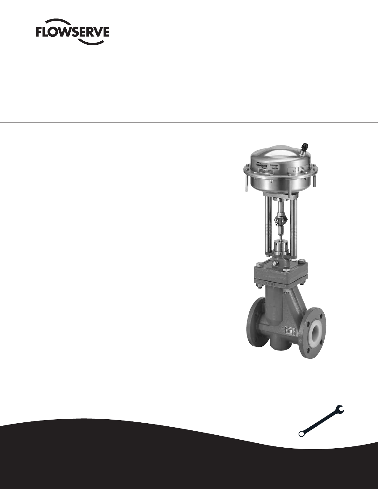
Kämmer ® LinedFlow™ - 132000
Valves for Corrosive Applications
FCD KMENIM3202-02 01/12
Installation
Operation
Maintenance
Experience In Motion
1
User Instructions LinedFlow - KMENIM3202-02 01/12
STOP!
STOP!
STOP!
STOP!
STOP!
®
INDEX
1 Using FLOWSERVE valves and actuators
and accessories correctly
2 Transport and storage
3 Installation
4 Intended use
5 Installation
6 Pressure test pipe section
7 Normal operation and maintenance
8 Trouble-shooting
9 Product description
10 Bonnet
11 Plug and seat
12 Bellows seal
1 3 Stem
14 Packing
15 Test connection
16 Quick check
17 Maintenance
18 Remove actuator from valve
19 Install actuator on valve
20 Disassemble and assemble valve
21 Trouble-shooting chart
1
USING KÄMMER VALVES AND ACTUATORS CORRECTLY
1.1 Use
FLOWSERVE control valves and actuators are intended
exclusively for control of mediums in an approved pressure
and temperature range after installation in a piping system
and connection of the actuator to the control system.
The permissible pressure and temperature limits are defined
in the operating instructions for the individual valve series.
1.2 Terms concerning safety
The safety terms DANGER, WARNING, CAUTION and NOTE
are used in these instructions to highlight particular dangers
and/or to provide additional information on aspects that
may not be readily apparent.
DANGER: indicates that death, severe personal injury and/
or substantial property damage will occur if proper precautions are not taken.
WARNING: indicates that death, severe personal injury and/
or substantial property damage can occur if proper precautions are not taken.
CAUTION: indicates that minor personal injury and/or pro-
perty damage can occur if proper precautions are not taken.
NOTE: indicates and provides additional technical infor-
mation, which may not be very obvious even to qualified
personnel. Compliance with other, not particularly emphasised notes, with regard to transport, assembly, operation and
maintenance and with regard to technical documentation
(e.g. in the operating instruction, product documentation or
on the product itself) is essential, in order to avoid faults,
which in themselves might directly or indirectly cause
severe personal injury or property damage.
2
1.3 Safety Notes for Operator
The manufacturer is not responsible for the following and it
is therefore necessary to ensure the following when using
FLOWSERVE control valves:
1.3.1 ...use valve as intended (Section 1)
DANGER: Never operate a control valve whose approved
pressure/temperature range according to the applicable
documentation for the valve series is not sufficient for the
operating conditions. Moreover, it must be ensured that the
valve is approved for the operating medium:
WARNING: Protection against incorrect use of control valve:
In particular, it is necessary to ensure that the selected
coating on the valve parts in contact with the medium are
suitable for the mediums, pressures and temperatures encountered. The manufacturer is not responsible for damage
to the valve resulting from corrosive mediums. Failure to
observe these precautions can pose a danger for the use
and cause damage to the piping system.
1.3.2 ...the piping system and control system must be installed
properly and checked regularly. The wall thicknesses of the
FLOWSERVE control valves correspond to the standards
and regulations for the pressure stage requirements of the
piping system in question.
1.3.3 ...the valves must be connected properly to this system.
1.3.4 ...the usual flow rates in continuous operation are not
exceeded in this piping system and abnormal operating
conditions such as vibration, water hammer, cavitation and
excessive quantities of solids in the medium – particularly
abrasive solids – must be clarified with the manufacturer.
WARNING: At temperatures > +50 °C and < -20 °C, it is
necessary to provide for protection against skin contact
including the piping connections.
1.4 Particular dangers
DANGER: The valve stem is sealed with a packing gland.
Before loosening or unscrewing the packing nut , ensure
that the pressure in the pipeline is completely relieved so
that the medium cannot escape through the packing.
Observe the usual safety precautions for hazardous medium
– particularly the use of protective clothing – when working
on the valves.
DANGER: On valves with a bellows seal also ensure that the
bellows does not leak by using a test connection, if present,
before removing the packing gland nut.
DANGER: Before removing the valve from the pipeline, en-
sure that the pressure in the pipeline is completely relieved
so that the medium does not escape uncontrolled from the
line.
WARNING: If it is necessary to remove a valve from the
pipeline, medium can escape from the line or from the valves. In the case of mediums which pose a health danger or
other danger, ensure that the pipeline is completely purged
before removing the valve.
User Instructions LinedFlow - KMENIM3202-02 01/12
STOP!
STOP!
STOP!
STOP!
STOP!
STOP!
STOP!
®
Observe caution with residues flowing out of the line or
remaining in the dead chambers of the valves. In the case of
dangerous mediums, observe the usual safety precautions
– particularly protective clothing.
WARNING: Disconnect or loosen the fastners – particularly
between bonnet and housing – only after the valve has been
removed. When reinstalling, tighten the bolts as specified in
these maintenance instructions using a torque wrench.
2 TRANSPORT AND STORAGE
Handle, transport and store FLOWSERVE control valves
carefully.
2.1 Store the valve in its protective packaging and/or with the
protective caps on the connection ends. Valves heavier
than approx. 10 kg should be stored and transported on a
pallet (or similarly supported, where applicable also on the
installation site).
WARNING: Do not place unpackaged valves on dirty
surfaces with the flange sealing surfaces. Hard and/or sharp
particles can damage the plastic lining.
2.2 During storage before installation, the valves should be
stored in a closed room as a rule and protected against
damaging influences such as dirt or moisture.
2.3 Large valves can be picked up using hoisting belts on
the yoke stems / eyes or - if present – on the supporting
shackles provided for this purpose. If hoisting belts are
used for unpacking, connect them so that the outer piping
and attached parts are not damaged.
WARNING: If hoisting belts are used, the center of gravity
of the valve can be higher than the connection point. In
such cases, secure the valve against turning or support it to
prevent injury or property damage.
In the event of transport damage, please contact your
FLOWSERVE representative immediately.
3 INSTALLATION
3.1 General
The same instructions apply for installing FLOWSER-
VE control valves in a pipeline as for connecting pipes
and similar piping elements with plastic liner materials. For control valves, the following instructions
apply in addition. Observe Section 3 for transport at
the installation site.
WARNING: Handle valves with particular care and observe
instructions for flange connections.
NOTE: As a rule, additional flange seals are not required.
The counterflanges must have smooth sealing surfaces in
all cases, e.g. Form C, Form D or Form E according to Standard DIN 2526 or Form B1 or B2 according to EN 1092-1
or stock finish according to ANSI B16.5. Other flange forms
must be coordinated with the manufacturer.
In addition, observe the following for actuators:
WARNING: Never subject actuators to external loads; this
can damage the valve – actuators are not step ladders -
WARNING: Heavy actuators must be supported in a suita-
ble manner if it is possible that their installation situation
would exert an impermissible bending force on the valve.
4 INTENDED USE
The series 132000 valves from Flowserve Essen GmbH
can be installed in all areas endangered by gas explosion,
because they do not have any potential ignition sources.
The valves can be used for shutting off the flow of noncombustible gaseous mediums and combustible gaseous
and fluid mediums far below the maximum explosion limit.
Inside the valve the atmospheric range is not reached under the conditions (see table below); here Directive 95/9/EC
is not applicable. Please note that certain (non-conductive)
mediums at certain flow rates can result in a potential
(static charge), which is subject to the operating conditions
and therefore is the responsibility of the operator.
Version Packing Seat Ring
Standard PTFE Compound PTFE Compound
4.1 Description of Unit
The valve is a lined control valve. The housing consists
of cast iron and the lining and gaskets are of elastomer
material.
The compatibility of the materials used with the surroun-
ding mediums must be observed in particular by the
operator.
4.2 Evaluation
Conformance with EN 13463, Parts 1 through 8 (non-
electrical explosion protection)
The fittings fulfill the following requirements.
4.2.1 All exposed parts were subjected to the impact and envi-
ronmental stress tests in conformance with
EN 13463-1 by the manufacturer and satisfy the require-
ments.
4.2.2 The valve body for the valves consists of cast iron. Formation of sparks resulting from the effect of exterior impact is
excluded under normal conditions.
5 INSTALLATION
WARNING: Plastic liners on the valves require particular
protection before/during installation; therefore:
CAUTION: Transport valve to installation site in protective
package if available. If flange covers are present, remove
them only immediately before installation.
5.1 Check valve for transport damage. Do not install damaged
valves.
Ensure that only valves are installed whose pressure class,
type of connection and connection dimensions satisfy the
installation conditions. See Markings and Valve specifications.
3
User Instructions LinedFlow - KMENIM3202-02 01/12
STOP!
®
DANGER: Do not install valves whose approved pressure
and temperature range is not sufficient for the operating
conditions. The limits for use are marked on the valves.
Moreover, use only valves suitable for the operating medium
in question.
Failure to observe these precautions can pose a danger for
the user and cause damage to the piping system.
5.2 The actuator must correspond to the intended connections
and control data.
5.3 The connection flanges must be inline with the valve
connections and parallel. Connection flanges which are not
parallel can damage the plastic liner during installation!
5.4 Before installing, thoroughly clean the valve and the pipeline
to remove any contamination, particularly hard foreign particles.
5.5 In particular, it is necessary to ensure that the sealing surfaces on the flange connection are free of all contamination
when installing.
5.6 When inserting the valve into a pipeline already installed, the
distance between the ends of the pipeline must be sufficient
to prevent damage to any of the sealing surfaces.
WARNING: Tighten all flange connections to the torques
specified in Tables 1a or 1b. When using torque wrenches,
ensure that these torques are reached, however not exceeded.
The values in the table apply for flanges according to
EN1092, PN10/16 for a maximum operating pressure of
10 bar. Values for other flanges can be obtained from the
manufacturer.
5.7 Valves are to be installed in the appropriate flow direction.
The flow direction is indicated by an arrow on the valve.
5.8 Observe the appropriate instructions for connecting the
actuator to the valve. Control valves are equipped with a
positioner. The connections for air supply and signals are
marked clearly (see also applicable operating instructions for
the positioner). The maximum air supply is specified on the
name plate. If the air supply exceeds the pressure specified
on the rating plate, a pressure reduction station is required.
If no instrument air is available, install an air filter in the air
supply line if required.
5.9 After completion of installation, perform a function test with
the control signals: The valve should open and close properly
corresponding to the control commands. Always eliminate
any recognizable malfunctions before startup. See also
applicable sections in maintenance regulations for this valve
series.
DANGER: Improperly executed control commands can pose
a danger for life and limb and damage to the piping system
and/or the valve.
6 PRESSURE TESTING PIPING SECTION
The valve has already been pressure-tested by the manuf-
acturer. When pressure testing a section of the pipeline with
valves installed, observe the following:
6.1 First thoroughly flush newly installed piping systems to
remove all foreign objects.
6.2 Valve opened: The test pressure should not exceed the
value of 1.5 x PN (according to nameplate):
6.3 Valve closed: The test pressure should not exceed the value
1.1 x PN (according to nameplate).
If a leak occurs on the valve, observe Section 8 “Trouble-
shooting”.
CAUTION: If the flange connection with plastic liner leaks:
First retighten flange connection to torque specified in Table
1a or 1b in Section 5.6 (installation).
If the flange connection is still leaks:
Loosen flange connection. Check the flange connection to
ensure that it is smooth and parallel.
Check the sealing surfaces on both flanges: When the inner
lining is damaged, replace valve and/or counterflange.
Table 1a: Tightening Torques for Flange Connections, Flanges EN1092 (DIN)
DN [mm] 15 20 25 40 50 80 100 150
M
[Nm] 10 18 25 50 65 65 65 140
A
Table 1b: Tightening Torques for Flange Connections, Flanges EN1759 (ANSI)
NW [inch] ½" ¾" 1" 1½" 2" 3" 4" 6"
M
[Nm] 8 11 15 26 60 100 76 100
A
4

®
7 NORMAL OPERATION AND MAINTENANCE
These installation, operating and maintenance instructions
cannot contain all detailed information on all possible
versions for reasons of clarity and, in particular, cannot take
into consideration all imaginable cases for setup, operation
and maintenance. Therefore, only primarily instructions
are contained, which are required for the intended use in
industrial applications. If anything is not clear, particularly if
any detailed information on the specific product is missing,
clarify as required with the responsible FLOWSERVE representative.
8 TROUBLESHOOTING
When troubleshooting or during general maintenance,
always observe Section 1 “Safety precautions”.
DANGER: If a valve contaminated with dangerous sub-
stances has to be removed from the system or pipeline,
decontaminate it properly before performing further maintenance work.
9 PODUCT DESCRIPTION
9.1 Housing
The body material is made of GGG40.3 (standard), other
body materials are also available from the manufacturer on
request. For valve bodies with plastic liners: See Table 2b
for coating materials.
The liner thickness is at least 5 mm for DN25 and higher
and 3.5 mm for DN15 and DN20.
10 BONNET
The bonnet is connected with a form fit to the valve body
providing, on the one hand, a potential compensation
between the housing and bonnet and on the other a defined
compression force for the body seal and bellows. The bonnet is provided with a blowout safety system. This means
that the valve stem cannot be pulled or pressed upward out
of the bonnet.
User Instructions LinedFlow - KMENIM3202-02 01/12
Table 2a: Body Specifications
Body material 0.7043 (GGG40.3)
Pressure class PN16
End connections
(Flanged)
DIN PN 16
ANSI Class 150
Liner thickness 4 – 6 mm
Table 2b: Liner Materials
PFA Perfluoralkoxypolymer
(Standard)
PFA conductive Perfluoralkoxypolymer,
electrically conductive
PVDF Polyvinilidenfuoride
ETFE Ethylene Tetrafluorethylene–
Copolymer (Tefzel
FEP Tetrafluorethylene
Perffluorpropylene
PP Polypropylene
®
)
11 PLUG AND SEAT
The seat and plug are screwed, i.e. replacement is possible
at any time when the Kvs value changes or for repair. The
plug is screwed to the bellows and secured against loosening by a PTFE insert. For smaller Kvs values, a Hastelloy
insert can be provided in the plug as well as in the seat (see
Table 3).
The possible material combinations and available Kvs values
and curves are shown in Table 3.
12 BELLOWS
The bellows seal is manufactured from modified PTFE.
TF1620 for DN15, DN20 and DN25 and TFM1600 for sizes
DN40, DN50, DN80 and DN100. The bellows is designed
and tested on a standard basis for an operating pressure of
16 bars at 120 °C. The pressure/temperature limitations are
limited only by the lining material, not the bellows: Observe
the additional operating forces required by the bellows for
sizing your actuator.
5

User Instructions LinedFlow - KMENIM3202-02 01/12
®
Table 3: Kvs / Cv Values
Plug Valve Size
Kvs / Cv-Values Seat DN15/20 DN25 DN 40 DN 50 DN 80 DN 100 DN 150
K
C
vs
v
0.011 3 0.12
0.017 3 0.12
0.025 0.029 3 0.12
0.040 0.047 3 0.12
0.063 0.074 3 0.12
0.10 0.12 4.5 0.18
0.16 0.19 4.5 0.18
0.25 0.29 4.5 0.18
0.40 0.47 4.5 0.18
0.63 0.74 4.5 0.18
1.0 1.2 7 0.28
1.6 1.9 7 0.18
2.5 2.9 10 0.25
4.0 4.7 12 0.30
5.0 5.8 15 0.38
6.3 7.4 16 0.41
10 12 20 0.51
13 25 0.64
16 19 25 0.64
25 29 32 0.81
32 40 1.02
40 47 40 1.02
47 50 1.27
63 74 50 1.27
100 120 63 1.60
120 139 80 2.03
160 190 80 2.03
180 100 2.54
250 290 100 2.54
340 400 125 3.18
Seat ø 0.5"/0.75" 1" 1½" 2" 3" 4" 6"
mm in. Stroke (mm/inch)
10/0.39 10/0.39
10/0.39 10/0.39
10/0.39 10/0.39
10/0.39 10/0.39
10/0.39 10/0.39
10/0.39 20/0.79
10/0.39 20/0.79
10/0.39 20/0.79
10/0.39 20/0.79
10/0.39 20/0.79
10/0.39 20/0.79
10/0.39 20/0.79
10/0.39 20/0.79
20/0.79 20/0.79
10/0.39
20/0.79 20/0.79 20/0.79
20/0.79 20/0.79
20/0.79
20/0.79 20/0.79 40/1.57
20/0.79 40/1.57
20/0.79
40/1.57 40/1.57
20/0.79
40/1.57 40/1.57
40/1.57 40/1.57
40/1.57
40/1.57
40/1.57
40/1.57
40/1.57
Hastelloy Hastelloy TFM1600
Hastelloy TFM1600 TFM1600
x
x
x
x
x
x
x
x
x
x
x
x
x
x
x
x
x
x
x
x
x
x
x
x
x
x
x
x
x
x
Tabelle 4: Bellows Seal
Size Seat/Plug Stroke (mm) Bellows Material Part No.
DN 15 TFM1600 10 HS22121 132538501 6,4
DN 20 TFM1600 10 HS22121 132538501 6,4
DN 25 TFM1600 10/20 HS22121 132538601 8,6
DN 40 TFM1600 20 HS22121 132538802 8,6
DN 50 TFM1600 20 HS22121 132538802 8,6
DN 80 TMF1600 40 HS22121 132538901 13,2
DN 100 TFM1600 40 HS22121 132538901 13,2
DN 150 TFM1600 40 HS22121 132539101 13,2
6
Effective area (cm2)

User Instructions LinedFlow - KMENIM3202-02 01/12
STOP!
STOP!
®
13 STEM
The valve stem is equipped with a blowout protection fea-
ture. This ensures that the valve stem cannot be removed
from the top of the valve. This is an important safety factor
when the actuator is removed from the valve, because there
would be otherwise no mechanical restriction.
Table 5: Valve stem materials
Valve stem 1.4571 (Standard)
14 PACKING
The 132000 valve series has a safety packing to back-up
the bellows seal and to prevent leakage to the outside in
the event of a bellows rupture.
15 TEST CONNECTION
WARNING: If the optional test connection (1/4” NPT) is
present, it must be sealed to prevent the medium from
exiting in the event of a bellows rupture.
16 Quick check
Before operating, check the valve as follows:
16.1 Open and close the valve and observe the movement of the
actuator stem. The movement should be smooth and linear.
16.2 Check the minimum stroke by changing the control signal
(for pneumatic position regulator 0.2 – 1.0 bar or corresponding “split range” values for IP position regulator 4-20
or 0-20 mA).
16.3 Check all air connections for leaks.
16.4 Check the packing nut (see Table 8).
CAUTION: An excessively tightened gland nut can cause
excessive packing wear and can hinder the free movement
of the plug stem.
16.5 Check fail-safe position. To do this, close supply pressure
and observe whether the valve opens or closes as defined.
16.6 After use under varying temperatures, retighten all threaded
connections and check for leaks.
17 MAINTENANCE
Check for proper function at regular intervals as follows.
These checks can be accomplished in the installed state
and, in many cases, without shutting down production. If
internal defects are suspected, see section “Disassembly
and assembly of valve”.
17.1 Check gaskets for leakage and retighten bolts if required
(see Fig. 1).
17.2 Check bellows seal, test connection and body drain screw –
if present – for leakage to the outside.
17.3 Check valve for damage resulting from corrosive process
residues or corrosive vapors.
17.4 Clean valves and repaint as required.
2.4819 (Hastelloy C276) (optional)
17.5 Check packing nut (see Table 8).
CAUTION: An excessively tightened gland nut can cause
excessive packing wear and can hinder the free movement
of the plug stem.
17.6 If possible, open and close valve and check for maximum
stroke and ensure that the plug stem moves without jerking.
Irregular motion of the plug stem can indicate an internal
defect
WARNING: ..Keep hands, hair, clothing, etc. away from all
moving parts. Failure to observe can lead to severe injuries.
17.7 Ensure that all accessory parts are seated tightly.
17.9 Connect air supply and check safety position.
Check air filter, if present, and replace element as necessary.
17.10
7
User Instructions LinedFlow - KMENIM3202-02 01/12
®
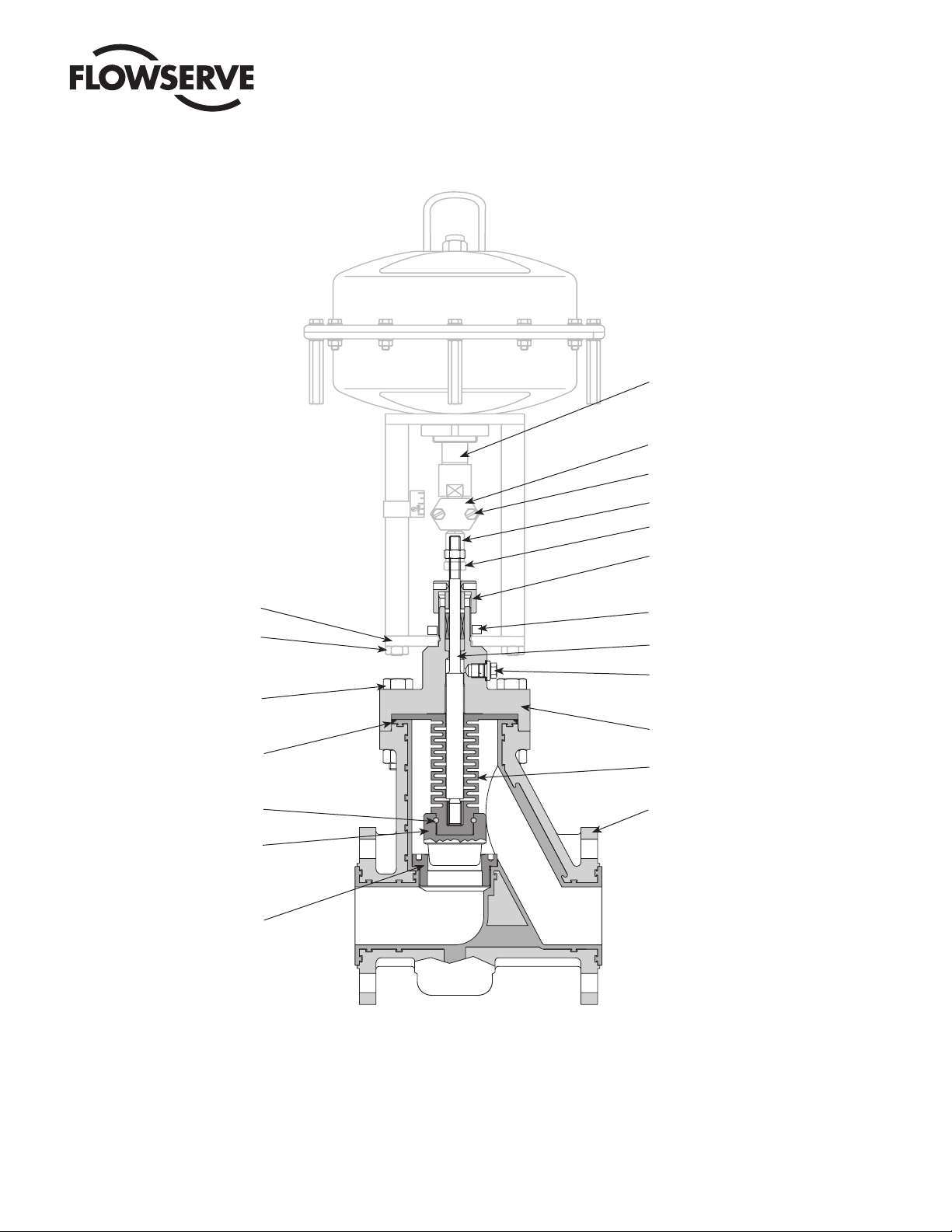
Actuator stem
Coupling
Coupling screw
Coupling insert
Locknut
Yoke plate
Yoke rod nut
Bonnet bolt
O-Ring (body/bonnet)
Insert, thread lock
Plug
Seat
Packing nut
Slotted nut
Plug stem
Test connection
(drawn rotated 90°)
Bonnet
Bellows seal
Body
Fig. 1: Typical Valve Series 132000 with Series 2 Actuator
8

®
18 REMOVING ACTUATOR FROM VALVE
(See Fig. 1)
18.1 Shut off air supply.
DANGER: Ensure that actuator is not under pressure and
drain process medium before performing maintenance
work. Failure to observe can lead to serious injuries.
18.2 Remove piping if required.
18.3 Remove 2 coupling bolts and remove coupling.
18.4 Loosen yoke stem nuts and remove. Carefully remove actuator from valve.
18.5 After loosening counternut, unscrew coupling insert (caution: hold plug with wrench on coupling insert to prevent
turning).
19 ATTACHING ACTUATOR TO VALVE
(see Fig. 1)
The actuator stem must be fully extended:
Actuators with air-to-open action must be fully vented.
Actuators with air-to-close action apply supply pressure.
Manually depress the plug stem to ensure the plug is fully
seated.
The valve plug must make contact in the valve seat, i.e.
press valve stem in all the way by hand.
19.1 Screw coupling insert locknut and coupling insert as far as
possible onto plug stem.
19.2 Place the actuator assembly on the valve engaging the
yoke rod threads in the lower yoke plate and ensuring the
actuator faces in the correct direction.
19.3 Unscrew the coupling insert until the yoke rods are raised
from the lower yoke plate by around 2 mm.
NOTE: Ensure that the plug assembly is not rotated with
the plug seated. This may cause irreparable damage to the
seating faces.
19.4 Refit the coupling, ensuring that the arrows, embossed on
the coupling halves, point upward towards the actuator,
and secure with 2 retaining screws.
User Instructions LinedFlow - KMENIM3202-02 01/12
9.5 Apply supply pressure resp. vent actuator to half stroke
and refit and tighten yoke rod retaining nuts.
19.6 Reconnect all tubing.
9

18
User Instructions LinedFlow - KMENIM3202-02 01/12
®
17
16
15
14
13
12
11
1 Bellows seal
2 O-Ring
3 Plug
4 Insert, thread lock
5 Seat
6 Body
1
7 nut
8 Plug
9 Seal (G¼
only with adapter)
10 Bushing
11 Bonnet
2
12 Screw
13 Slotted nut
3
14 Stem
15 Packing
16 Packing follower
17 Packing nut
4
9
8
5
18 Nut
10
10
7
Fig. 2: Individual Parts for Series 132 000
(also see spare parts lists)
Table 6: Tightening Torque for Seat (Nm)
DN 15 DN 20 DN 25 DN 40 DN 50 DN 80
6 6 6 25 25 35
Table 7: Tightening Torque for Bonnet Fastners (Nm)
DN 15 DN 20 DN 25 DN 40 DN 50 DN 80 DN1 100 DN 150
60 60 60 145 145 145
6
1DN 1002
55
280
DN 150
70
250
10

User Instructions LinedFlow - KMENIM3202-02 01/12
STOP!
STOP!
®
20 DISASSEMBLE AND ASSEMBLE VALVE
20.1 DISASSEMBLE VALVE
(see Fig. 2)
DANGER: As toxic or hazardous substances could be
present, release all pressure in the system and drain all
process substances. If necessary, decontaminate valve.
Keep hands, hair and clothing away from moving parts.
Wear face and eye protection. Failure to observe can lead to
severe injuries.
20.1.1 Carefully loosen test connection and check whether medium has collected in bellows cap (bellows defective).
20.1.2 Remove bolts/nuts from bonnet and remove bonnet.
Note: Due to packing friction the bellows/plug is usually
pulled out when the bonnet is removed. In such cases, hold
the bellows/plug so that it cannot fall and be damaged.
20.1.3 If the bellows remains in the housing, it can be pried out
carefully with two screwdrivers.
20.1.4 Without stretching the bellows, remove the plug/bellows
assembly from the bonnet. Press guides, packing and
spacer out of packing chamber from below with a punch
(the punch diameter should be slightly larger than the plug
stem).
20.1.5 If required, pull out thread lock insert with a pair of pliers
and unscrew plug from bellows.
WARNING: When the plug is loosened, medium residues
can be released which have leaked through the thread.
20.1.7 Unscrew seat ring with seat ring wrench.
20.1.8 Check sealing edges on seat ring and plug for damage. The
sealing surfaces must be clean and free of damage.
WARNING: To avoid damage to the seat, plug or plug stem,
observe the preceding instructions exactly.
20.2 ASSEMBLE VALVE
(see Fig. 2)
20.2.1 Replace all worn or damaged parts. Use only genuine
FLOWSERVE parts. Parts to be reused must be clean.
Always replace parts subject to wear such as gaskets,
packings and O-rings.
20.2.2 Insert seat ring and tighten (see Table 6 for torque).
20.2.3 Screw plug onto bellows hand-tight and insert a new thread
lock insert. Cut off thread lock insert so that approx. 3 mm
extends from the hole.
20.2.4 Carefully insert plug stem with bellows into bonnet.
20.2.5 Position new O-ring on inclined surface on top of housing.
20.2.6 Position bonnet slowly and absolutely upright on body, to
avoid damage to seat/plug.
20.2.7 Insert bonnet mounting bolts and tighten hand-tight in
crisscross pattern.
20.2.10 Tighten all bolts to specified torques in crisscross pattern
with torque wrench (see Table 7).
20.2.11 Replace packing by inserting packing rings one at a time
tapping each one down with a suitable bushing.
NOTE: ensure that the gaps in the packing rings are distri-
buted evenly around the circumference in the packing box
(gaps not in line).
Different packings and fitting sequencess are shown in the
spare parts list.
Insert packing follower and tighten packing nut (see Table 8).
20.2.12
20.2.13 During the subsequent pressure test, ensure that the pressure does not exceed the maximum permissible pressure
for the bellows (PN16). After checking the test connection
for leakage – if present – plug with a plug or appropriate
pressure gauge.
Table 8: Tightening Torque for Packing Nut (Nm)
Thread
M20 x 1,5 1
M30 x 1,5 6
M38 x 1,5 15
M45 x 1,5 17
PTFE
11

®
22 TROUBLE-SHOOTING CHART
Fault Possible Cause Remedy
1.
Stem motion
impeded
Excessive
leakage
Inadiquate flow 1.
Plug slams 1.
1.
Packing excessively tightened
2.
Operating temperature too high for selected
trim
Supply pressure inadiquate
3.
Positioner defective
4.
Bonnet loose
1.
Worn or damaged seat ring/plug
2.
Gaskets damaged
3.
Inadiquate actuator thrust
4.
Plug incorrectly adjusted
5.
Incorrect direction of flow
6.
Handwheel incorrectly adjusted
7.
(acts like end stop)
Plug incorrectly adjusted (short stroke)
Positioner defective
2.
Operating requirements too high
3.
Plug adjustment incorrect
Inadiquate supply pressure
2.
Trim too large for flow rate
3.
Tighten gland nut
2.
Note operating data and contact dealer
3.
Check system for leaks in the supply pressure or signal lines. Retighten the connections, if necessary replace leaky lines
See operating instructions for positioner
4.
See step 20.2.7 for correct tightening of bonnet
1.
Re-machine or replace seat ring/plug
2.
Replace gaskets
3.
Check air feed. If air feed is OK, contact dealer.
4.
Correctly adjust plug according to step
5.
Check specification. Contact dealer
6.
Adjust handwheel
7.
Correctly adjust plug
1.
See operating instructions for positioner
2.
Check operating data. Contact dealer
3.
Correctly adjust plug
1.
Check supply pressure, seal leaks, remove blockage
2.
Replace trim
3.
User Instructions LinedFlow - KMENIM3202-02 01/12
Germany
Flowserve Essen GmbH
Schederhofstr. 71
45145 Essen
Deutschland
Tel.: +49 (0)201 8919 5
Fax: +49 (0)201 8919 662
Your Contact:
All data subject to change without notice
© 07.2003 Flowserve Corporation. Flowserve and Kämmer are trademarks of Flowserve Corporation
USA
Flowserve Corporation
1300 Parkway View Drive
Pittsburgh, PA 15205
USA
Tel.: +1 412 787 8803
Fax: +1 412 787 1944
Singapore
Flowserve Pte Ltd
12 Tuas Avenue 20
Singapore, 638824
Singapore
Tel.: +65 6879 8989
Fax: +65 6862 4940
12
flowserve.com
 Loading...