

Fisher & Paykel DE09, DG09, DE60FA, DG60FA Service Manual

479536
Service Manual
Dryers
Models:
DE09 / DG09
DE60FA / DG60FA

479536
Fisher & Paykel Appliances Inc
5800 Skylab Rd,
Huntington Beach
California, CA92647
USA
Telephone: 888 936 7872
E-mail: customer.care@fisherpaykel.com
Fisher & Paykel Appliances Canada Inc
2900 – 595 Burrard Street
Vancouver
BC, V7X 1J5
Canada
Telephone: 888 936 7872
E-mail: customer.care@fisherpaykel.com
COPYRIGHT © FISHER & PAYKEL LTD 2008 - ALL RIGHTS RESERVED
2

479536
3
CONTENTS
1 INTRODUCTION......................................................................................................................5
1.1 Overview .............................................................................................................................5
1.2 Air Flow ...............................................................................................................................5
2 INSTALLATION....................................................................................................................... 6
2.1 Electric Model Installation.................................................................................................... 6
2.2 Gas Model Installation....................................................................................................... 11
3 SPECIFICATIONS.................................................................................................................17
3.1 DE09 and DE60FA Specifications..................................................................................... 17
3.2 DG09 and DG60FA Specifications.................................................................................... 18
3.3 Serial Plate Location .........................................................................................................18
4 COMPONENT SERVICING...................................................................................................19
4.1 Top Disassembly............................................................................................................... 19
4.1.1 Timer Replacement .................................................................................................... 20
4.1.2 Selector Switch Replacement..................................................................................... 21
4.1.3 Auto Dry PCB Replacement....................................................................................... 22
4.2 Drum Removal .................................................................................................................. 22
4.2.1 Drum Rear Sleeve And Shaft Replacement ............................................................... 23
4.2.2 Drum Baffle Replacement .......................................................................................... 23
4.2.3 Front Bearing Assembly and Front Panel Component Replacement......................... 23
4.3 Cowl Replacement and Components................................................................................ 24
4.3.1 Electric Model Cowl.................................................................................................... 24
4.3.2 Electric Cowl Wiring Diagram..................................................................................... 24
4.3.3 Gas Model Cowl ......................................................................................................... 25
4.3.4 Gas Cowl Wiring Diagram .......................................................................................... 25
4.4 Gas Valve Assembly Replacement ................................................................................... 26
4.4.1 Flame Detect Thermostat Replacement..................................................................... 26
4.5 Motor, Outlet Thermostat, Jockey Pulley and Belt Switch Replacement........................... 27
4.5.1 Motor and Outlet Thermostat Wiring Diagrams .......................................................... 28
4.6 Power Supply Connections ...............................................................................................29
4.6.1 Electric Terminal Block............................................................................................... 29
4.6.2 Gas and Electric Model Cable.................................................................................... 29
5 OPERATION.......................................................................................................................... 29
5.1 Operating Instructions - Control Panel .............................................................................. 29
5.2 Using the Dryer .................................................................................................................30
5.3 Operational Control Sequence .......................................................................................... 32
5.3.1 Motor Operation.......................................................................................................... 32
5.3.2 Timer Operation.......................................................................................................... 33
5.3.3 Element Operation (Electric Models).......................................................................... 35
5.3.4 Thermostat Operation (Electric Model)....................................................................... 36
5.3.5 Gas Valve & Ignitor Circuit Operation (Gas Models) .................................................. 38
5.3.6 Thermostat Operation (Gas Model)............................................................................ 39
6 FAULT FINDING....................................................................................................................42
6.1 Fault Finding...................................................................................................................... 42
7 FLOW CHARTS .................................................................................................................... 45
7.1 Electric Flow Chart ............................................................................................................ 45
7.2 Gas Flow Chart .................................................................................................................46
8 WIRING DIAGRAMS.............................................................................................................47
8.1 Electric Wiring Diagram..................................................................................................... 47
8.2 Gas Wiring Diagram .......................................................................................................... 48
9 SEQUENCE CHARTS...........................................................................................................49
9.1 Electric Timer Sequence ................................................................................................... 49
9.2 Gas Timer Sequence ........................................................................................................49

479536
4
9.3 Electric Selector Sequence................................................................................................49
9.4 Gas Selector Sequence.....................................................................................................50
479536
5
1 INTRODUCTION
This service manual is designed to show all components and servicing of the DE/DG09 and
DE/DG60FA Dryers.
These dryers are only sold in the USA and Canada.
1.1 Overview
These models are front-loading dryers, which run a semi analogue/electronic control system. All
switching for the dryer is carried out by the timer, selector switches, thermostats and motor, but the
auto-dry is controlled by the PCB assembly.
The motor is a single phase, single direction motor with a centrifugal start.
The electric models have a coil element design mounted to a cowl on the rear of the drum.
The gas models run a burner, from where the heat is ducted into the cowl. These can be run on
natural gas or can be converted to LP gas.
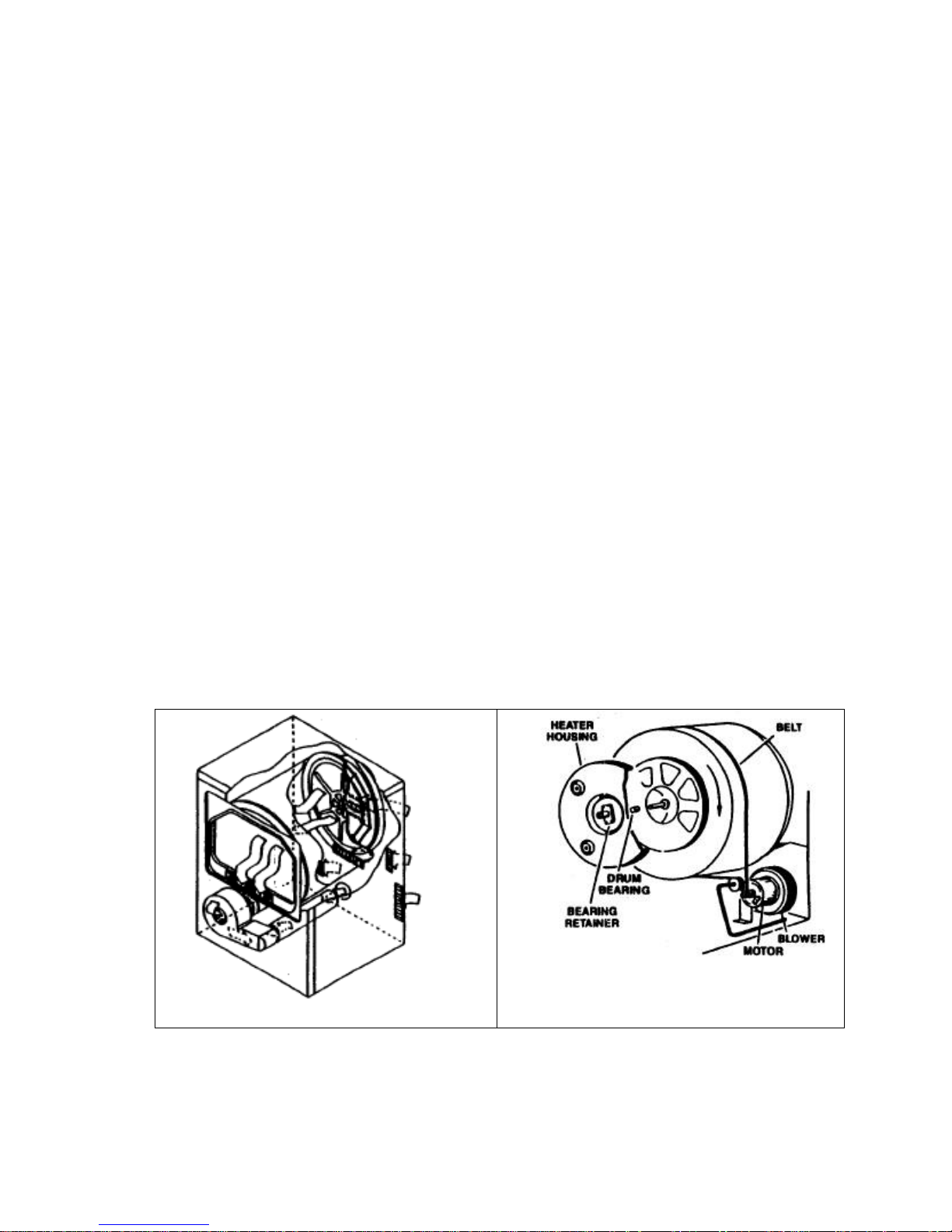
1.2 Air Flow
Air is pulled into the cabinet from the rear by the fan.
In gas models, air pulled through the burner assembly. The heated air then flows through the drum
cowl and into the drum.
In electric models, the air pulled from the fan is blown into the elements in the cowl and is heated.
It then flows into the drum.
Air from the drum is pulled through the clothes and into the lint filter. The air is then drawn into the
fan and them blown out the exhaust system. The blower is mounted directly to the motor shaft.
Air Flow Drum Operation
479536
6
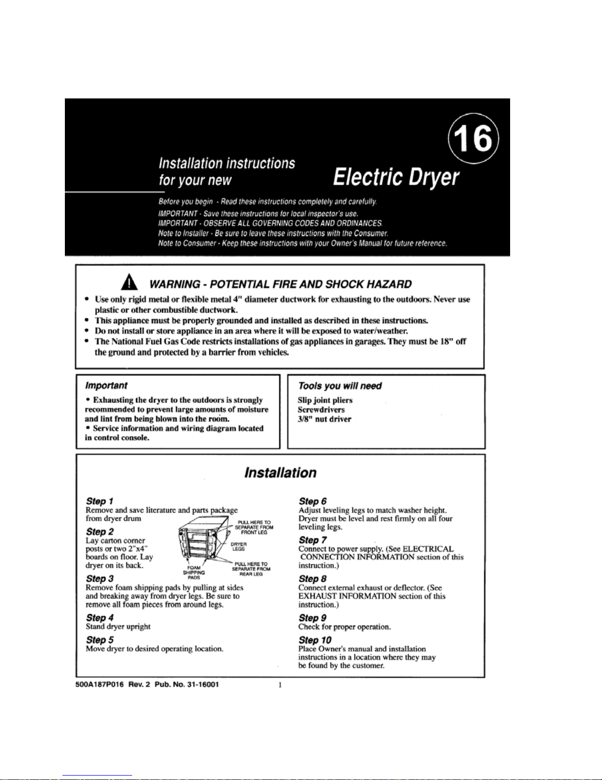
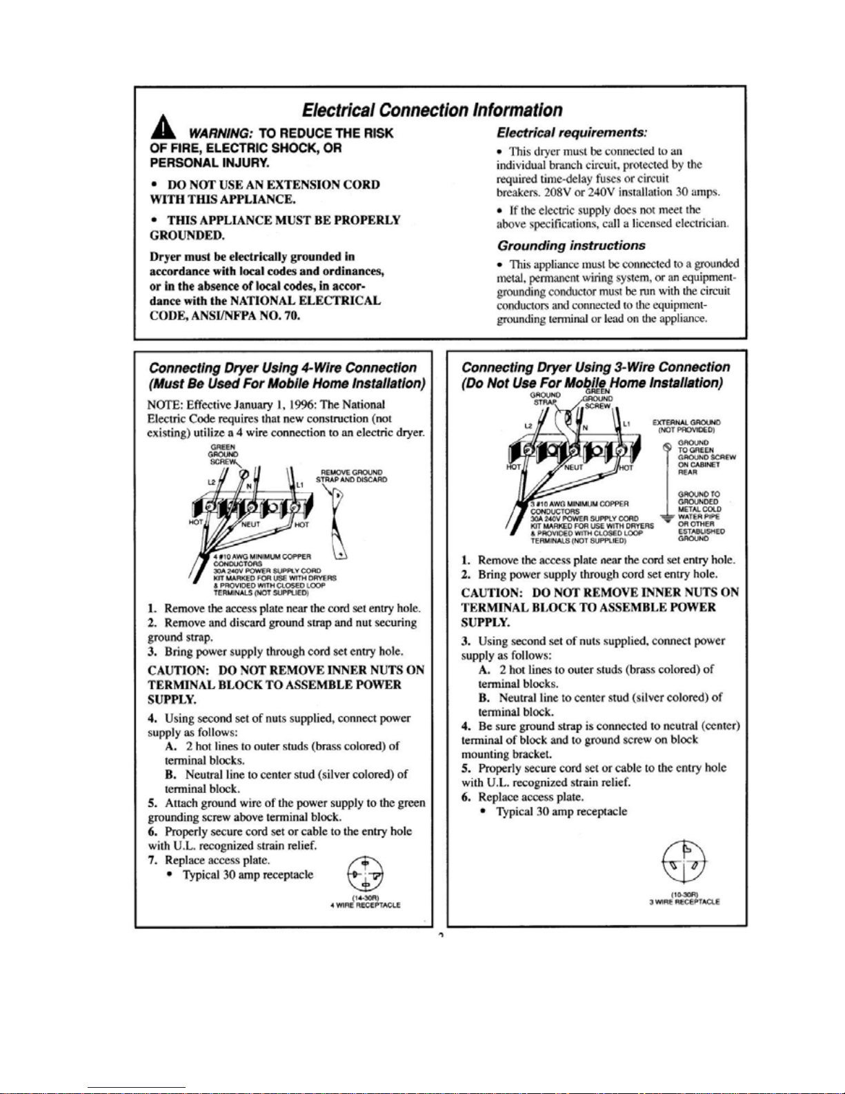
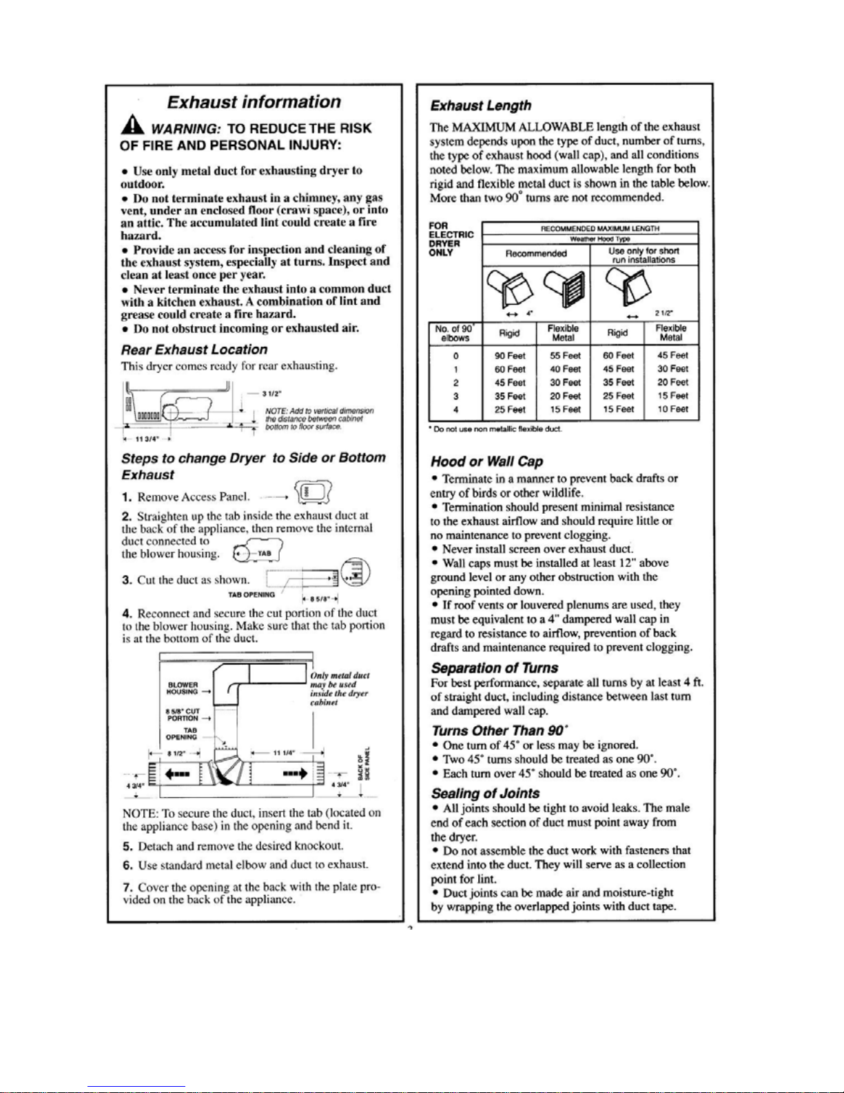
2 INSTALLATION
2.1 Electric Model Installation
479536
7
479536
8
479536
9
479536
10
479536
11
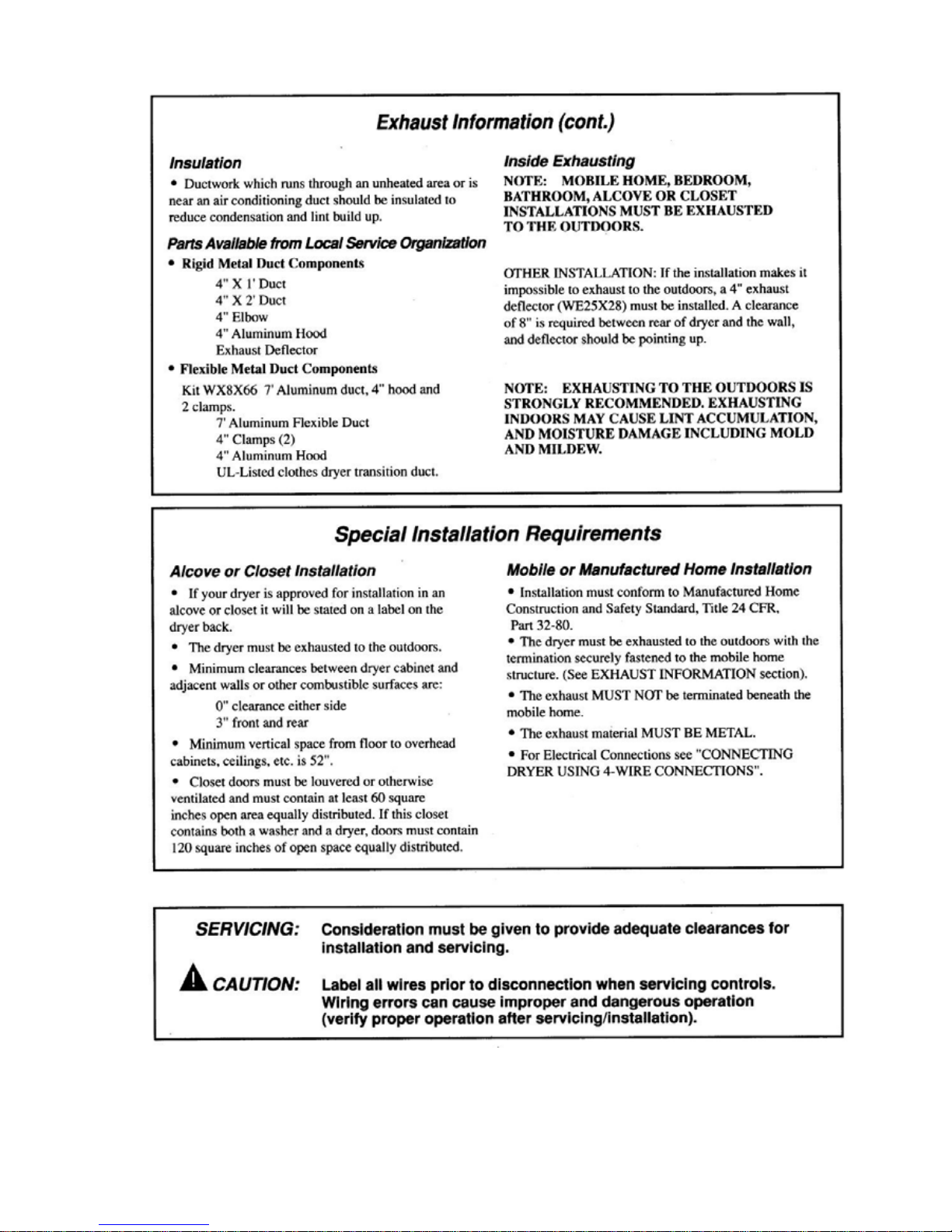
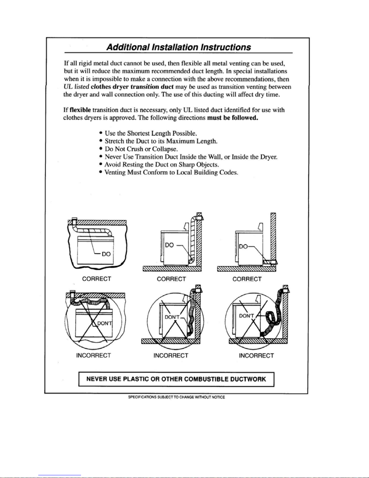
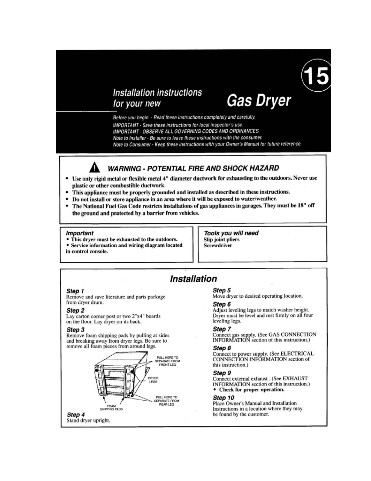
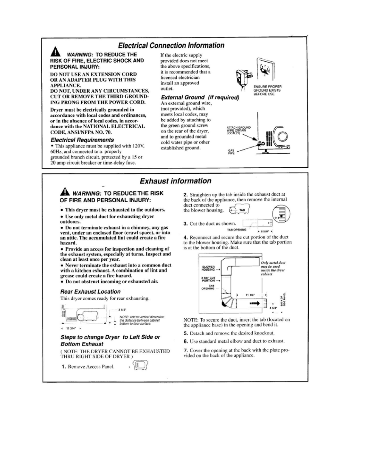
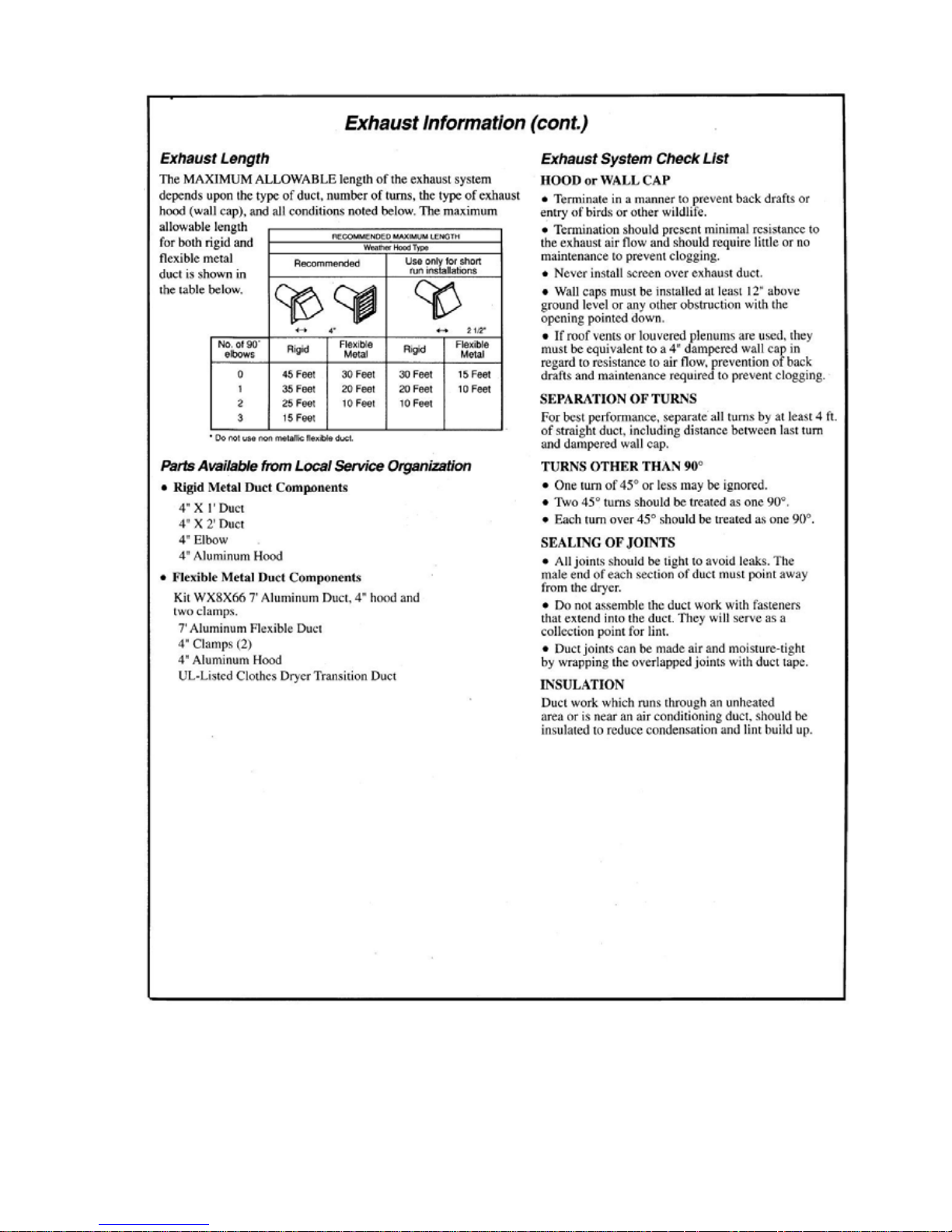
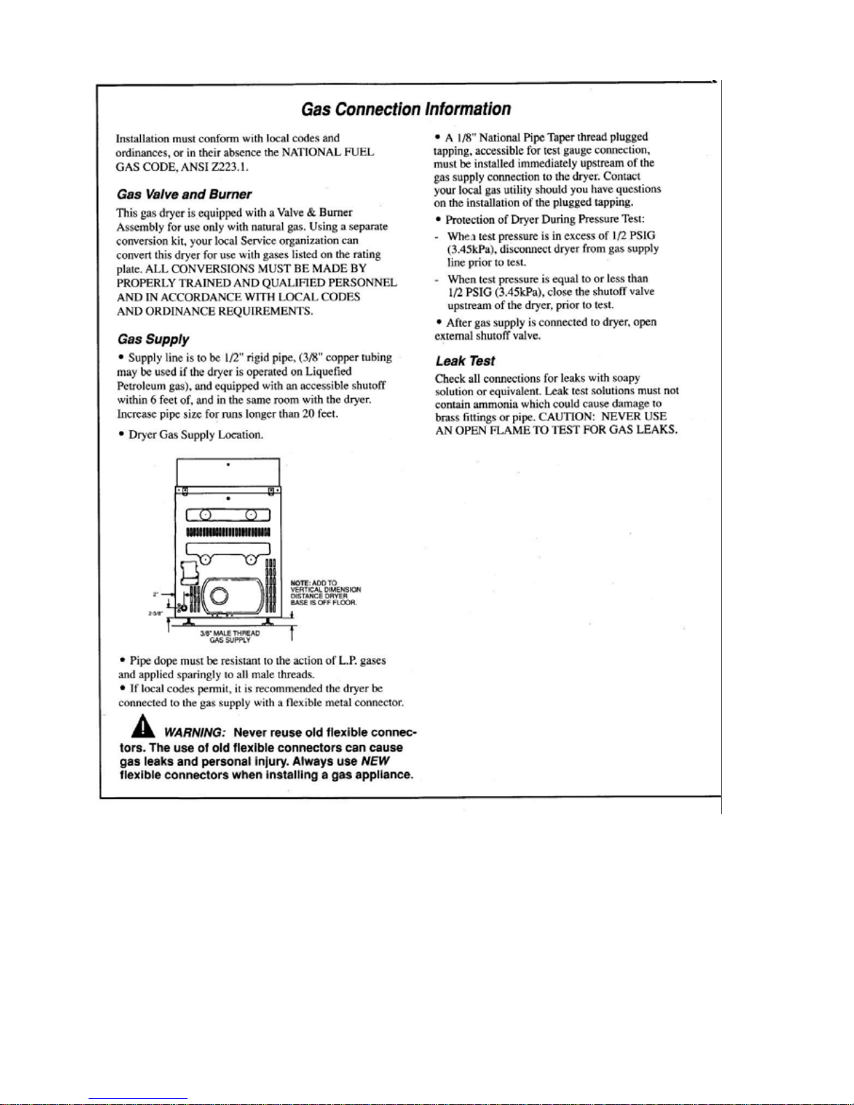
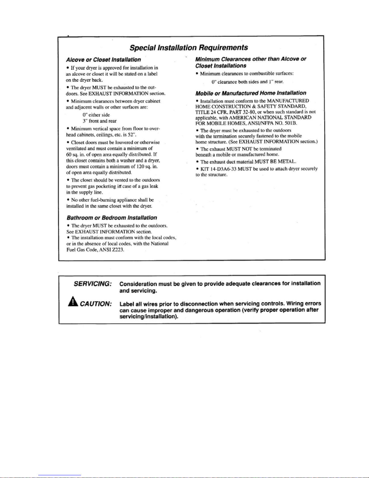
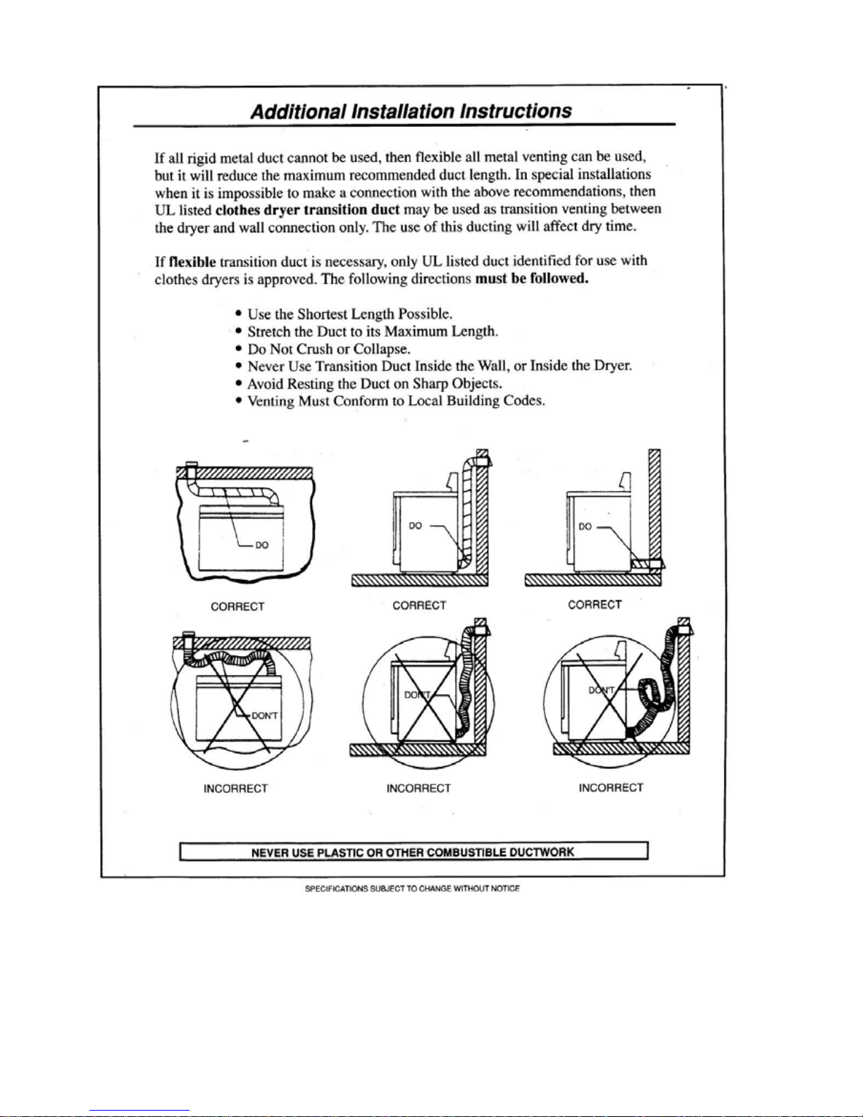
2.2 Gas Model Installation
479536
12
479536
13
479536
14
479536
15
479536
16
 Loading...