

Page 1

MS-25/MS-25C/MS-25E
Addressable Fire Control Panel
Inst allation/Operation Manual
Document 53688
06/06/11 Rev:
P/N 53688:C ECN 11-0214
1 Firelite Place Northford, CT 06472-1653 USA TEL: (203) 484-7161
C
Page 2

Page 3

Installation Procedure
Installation Precautions - Adherence to the following will aid in problem-free installation
with long-term reliability: WARNING - Several different sources of power can be connected
to the fire alarm control panel. Disconnect all sources of power before servicing. Control unit
and associated equipment may be damaged by removing and/or inserting cards, modules, or
interconnecting cables while the unit is energized. Do not attempt to install, service, or operate
this unit until manuals are read and understood. CAUTION - System Re-acceptance T est after
Software Changes: To ensure proper system operation, this product must be tested in
accordance with NFPA 72 after any programming operation or change in site-specific
software. Re-acceptance testing is required after any change, addition or deletion of system
components, or after any modification, repair or adjustment to system hardware or wiring. All
components, circuits, system operations, or software functions known to be affected by a
change must be 100% tested. In addition, to ensure that other operations are not inadvertently
affected, at least 10% of initiating devices that are not directly affected by the change, up to a
maximum of 50 devices, must also be tested and proper system operation verified. This
system meets NFP A requirements for operation wi thin the range of 0°C-49°C (32°F-120°F) or
humidity within the range of 10%-93% at 30°C (86°F) noncondensing. However, the useful
life of the system's standby batteries and the electronic components may be adversely affected
by extreme temperature ranges and humidity. Therefore, it is recommended that this system
and its peripherals be installed in an environment with a normal room temperature of 15-27º
C/60-80º F. Verify that wir e sizes ar e adequate for all initiating and indicating device loops.
Most devices cannot tolerate more than a 10% I.R. drop from the specified device voltage.
Like all solid state electronic devices, this system may operate erratically or can be damaged
when subjected to lightning induced transients. Although no system is completely immune
from lightning transients and interference, proper grounding will reduce susceptibility.
Overhead or outside aerial wiring is not recommended, due to an increased susceptibility to
nearby lightning strikes. Consult with the Technical Services Department if any problems are
anticipated or encountered. Remove DC power prior to removing or inserting circuit boards.
Failure to do so can damage circuits. Remove all electronic assemblies prior to any drilling,
filing, reaming, or punching of the enclosure. When possible, make all cable entries from the
sides or rear. Before making modifications, verify that they will not interfere with battery,
transformer, or printed circuit board location. Do not tighten scr ew terminals more than 9 inlbs. Over-tightening may damage threads, resulting in reduced terminal contact pressure and
difficulty with screw terminal removal. Fire alarm control panels contain static-sensitive
components. Always ground yourself with a proper wrist strap before handling any circuits so
that static charges are removed from the body. Use static suppressive packaging to protect
electronic assemblies removed from the unit.
Follow the instructions in the installation, operating, and programming manuals. These
instructions must be followed to avoid damage to the control panel and associated equipment.
FACP operation and reliability depend upon proper installation.
Page 4

Equipment used in the system may not be technically compatible with the control. It is
essential to use only equipment listed for service with your control panel. Telephone lines
needed to transmit alarm signals from a premise to a central monitoring station may be out of
service or temporarily disabled. The most common cause of fire alarm malfunctions,
however, is inadequate maintenance. All devices and system wiring should be tested and
maintained by professional fire alarm installers following written procedures supplied with
each device. System inspection and testing should be scheduled monthly or as required by
National and/or local fire codes. Adequate written records of all inspections should be kept.
Page 5

Contents
Contents
Section 1
Introduction ..............................................................................................................................................1-1
1.1 Overview of Basic System ....................................................................................................................... 1-1
1.1.1 Hardware Features .......................................... .................................................................................. 1-1
1.1.2 Software Features .............................................................................................................................1-1
1.2 About this Manual ....................................................................................................................................1-2
1.2.1 Terms Used in this Manual ...............................................................................................................1-2
1.3 Compatible Products ................................................................................................................................1-2
Section 2
Agency Listings, Approvals, and Requirements ...................................2-1
2.1 Federal Communications Commission (FCC) .........................................................................................2-1
2.2 Underwriters Laboratories (UL) ................. .............................................................................................2-3
2.2.1 Requirements for All Installations ....................................................................................................2-3
2.2.2 Requirements for Central Station Fire Alarm Systems ....................................................................2-4
2.2.3 Requirements for Local Protected Fire Alarm Systems ...................................................................2-4
2.2.4 Requirements for Remote Station Protected Fire Alarm Systems ........................................... ......... 2-4
2.3 ULC Requirements ..................................................................................................................................2-4
Section 3
Before You Begin Installing ............................................................................................... 3-1
3.1 What’s in the Box? ...................................................................................................................................3-1
3.2 Environmental Specifications ..................................................................................................................3-1
3.3 Electrical Specifications ........................................................................................................................... 3-2
3.4 Wiring Specifications ........................................................ ....................................................................... 3-3
3.5 Board Assembly Diagram ........................................................................................................................3-4
3.6 Calculating Current Draw and Standby Battery ......................................................................................3-5
3.6.1 Worksheet Requirements ..................................................................................................................3-5
3.6.1.1 Current Draw Worksheet for MS-25 UL 864 ........................................................................ 3-6
3.6.1.2 Current Draw Worksheet for MS-25C ULC ........................................... ...............................3-8
3.6.2 Maximum Battery Standby Load for UL 864 .................................................................................3-10
3.6.3 Maximum Battery Standby Load for ULC ..................................................................................... 3-10
Section 4
Control Panel Installation ......................................................................................................4-1
4.1 Mounting the Control Panel Cabinet ....................................................................................................... 4-1
4.1.1 Preventing Water Damage ................................................................................................................4-1
4.1.2 Removing the MS-25 Assembly from the Housing ..........................................................................4-1
4.1.3 Dead Front Installation and removal ................................................................................................4-2
4.1.3.1 Installing the Dead Front ........................................................................................................ 4-2
1
Page 6

Contents
4.1.3.2 Dead Front Removal .............................................................................................................. 4-3
4.2 AC Power Connection .............................................................................................................................4-4
4.2.1 AC Power Connection for UL 864 applications ...............................................................................4-4
4.2.2 AC Power Connection for Canadian Applications ...........................................................................4-5
4.3 Battery Connection ..................................................................................................................................4-6
4.4 SBUS Wiring ........................................................................................................................................... 4-7
4.4.1 Calculating Wiring distance for SBUS modules ..............................................................................4-7
4.4.2 Wiring Configurations .............................................................................. ... ..................................... 4-9
4.5 ANN-80 Remote Annunciator Installation ............................................................................................4-10
4.5.1 Mounting the ANN-80 ....................................................................................................................4-11
4.6 Model ANN-80 Connection to the Panel ...............................................................................................4-12
4.7 Configuring Module ............................................................................................................................... 4-13
4.7.1 Assigning Module IDs ....................................................................................................................4-13
4.8 Telephone Connection ........................................................................................................................... 4-14
4.9 Notification Appliance/Auxiliary Power Circuits ..................................................................................4-15
4.9.1 Conventional Notification Appliance Circuit .................................................................................4-15
4.9.2 Auxiliary Power Installation ...........................................................................................................4-16
4.9.2.1 Door Holder Power .............................................................................................................. 4-16
4.9.2.2 Constant Power ....................................................................................................................4-17
4.9.2.3 Resettable Power ....................................................................... ........................................... 4-17
4.10 On-Board Relays (Conventional, Power Limited) .................................................................................4-18
4.10.1 Common Trouble Relay .................................................................................................................. 4-18
4.10.2 Programmable Relays ............................................................ .........................................................4-18
4.11 Remote Station Applications .................................................................................................................4-19
4.11.1 City Box Connection Using the 5220 Module ................................................................................4-19
4.11.2 NFPA 72 Polarity Reversal ............................................................................................................. 4-21
4.11.2.1 Alarm, Supervisory and Trouble Reverse Polarity Outputs ................................................4-21
Section 5
SLC Device Installation ............................................................................................................5-1
5.1 List of SLC Devices .................................................................................................................................5-1
5.2 Maximum Number of Devices .................................................................................................................5-1
5.3 Wiring Requirements for SLC Devices ................................................... ................................................5-2
5.3.1 Wiring SLC in Style 4 (Class B) Configuration .................................. ............................................. 5-2
5.4 Wiring SLC Detectors .......................................................... ....................................................................5-5
5.5 Addressing SLC Devices ..................................................... ... ..................................... ............................5-6
Section 6
Programming ......................................................................................................................................... 6-1
6.1 UL 864 Programming Requirements .......................................................................................................6-1
6.2 Control Panel Programming .....................................................................................................................6-2
6.3 Default Control Panel Configuration. ......................................................................................................6-2
6.3.1 Default Mapping of SLC Inputs to Outputs ......................................................................................6-2
6.3.2 Mapping of SLC Inputs to Outputs. .................................................................................................6-2
6.3.3 Default Mapping for the 2 built-in Notification Circuits. .................................................................6-3
6.3.4 Maximum SLC address point count ................................................................................................. 6-4
6.3.5 Installer Code ............................................ ..................................... ...................................................6-4
6.4 JumpStart Auto Programming .................................................................................................................6-4
6.5 Modifying Panel Programming using a PC .............................................................................................6-5
2
Page 7

Contents
6.5.1 Connecting the panel to a PC ............................................................................................................6-5
6.6 Panel Programming Options ....................................................................................................................6-6
6.6.1 System Options .................................................................................................................................6-6
6.6.1.1 Synchronized Strobes Active When Horns Silenced ............................................................. 6-6
6.6.1.2 Silence/Reset Inhibit Enabled .................................. ..............................................................6-6
6.6.1.3 Water Flow Delay ........................................... .......................................................................6-6
6.6.1.4 Installer Code (User ID) .........................................................................................................6-6
6.6.1.5 Alarm Verification Time ........................................................................................................6-6
6.6.1.6 Auto Test ................................................................................................................................6-6
6.6.1.7 Low AC Report Delay ...........................................................................................................6-6
6.6.1.8 Walk Test Reporting .......................................... ....................................................................6-7
6.6.1.9 Walk Test duration ................................................................................................................. 6-7
6.6.1.10 Walk Test NAC Time out .....................................................................................................6-7
6.6.1.11 Clock Source .........................................................................................................................6-7
6.6.1.12 Auto Daylight Savings Time .................................................................................................6-7
6.6.1.13 Remote Annunciator .............................................................................................................6-7
6.6.2 Zone Programming ...........................................................................................................................6-8
6.6.2.1 SLC Addresses Within Each Zone .........................................................................................6-8
6.6.2.2 Zone Silenceable ....................................................................................................................6-8
6.6.2.3 Zone Type .............................................................................................................................. 6-8
6.6.3 Output Point Programming .................................................... ....................................... ....................6-8
6.6.4 Notification Appliance Circuit (NAC) Programming ......................................................................6-9
6.6.4.1 Circuit Function ............................................................... ... ...................................................6-9
6.6.4.2 Conventional Notification Circuit Mapping .......................................................................... 6-9
6.6.5 Relay Programming Options .......................................................................................................... 6-10
6.6.5.1 General System Relay Silence Option .................................................................................6-10
6.6.6 Dialer Phone Line Programming Options ......................................................................................6-10
6.6.6.1 Line Prefix ............................................................................................................................6-10
6.6.6.2 Dial Tone Detection .............................................................................................................6-10
6.6.6.3 Line Monitoring Enabled (Y/N) ..........................................................................................6-10
6.6.6.4 Dialing Option ...................................... ... ..................................... .. ...................................... 6-10
6.6.6.5 Pulse Dialing Format ..................................................................... ...................................... 6-10
6.6.7 Dialer Account programming Options ...........................................................................................6-11
6.6.7.1 Account Number ..................................................................................................................6-11
6.6.7.2 Phone Number ...................................................................................................................... 6-11
6.6.7.3 Reporting Format ................................................................................................................. 6-11
6.6.7.4 Reporting Filters ..................................................................................................................6-11
Section 7
System Operation ............................................................................................................................7-1
7.1 System Reset ............................................................................................................................................ 7-1
7.2 Lamp Test ................................................................................................................................................ 7-1
7.3 System Silence .........................................................................................................................................7-1
7.4 Acknowledge ........................................................................................................................................... 7-1
7.5 Viewing Active Alarm Points ............................................................ ......................................................7-1
7.6 Viewing Active Supervisory Points .........................................................................................................7-2
7.7 Viewing Active Trouble Points ................................................................................................................ 7-2
7.8 Walk Test ......................................... ........................................................................................................7-2
7.9 Fire Drill ...................................................................................................................................................7-2
7.10 Zone Disable Feature ............................................................................................................................... 7-3
7.11 Disabling Notification Circuits ............................................ ........................................ ............................7-3
3
Page 8

Contents
7.12 Loss of AC power ....................................................................................................................................7-3
7.13 Remote Connection Feature (ULC Installations Only) ............................................................................7-3
7.14 Low Battery ..............................................................................................................................................7-4
7.15 Ground Fault ............................................................................................................................................7-4
7.16 Phone Line Monitoring ...........................................................................................................................7-4
7.17 Reporting Account Monitoring ................................................................................................................7-4
7.18 SLC Fault .................................................................................................................................................7-4
7.19 Dialer Error ..............................................................................................................................................7-4
7.20 Annunciator Description ..........................................................................................................................7-5
7.20.1 LCD Displays ...................................................................................................................................7-5
7.20.2 Banner ...............................................................................................................................................7-6
7.21 Basic Operation ........................................................................................................................................7-7
7.21.1 Conduct a Fire Drill ..........................................................................................................................7-7
7.21.2 Conduct an Indicator Test .................................................................................................................7-7
7.21.3 Silence alarms or troubles .................................................................................................................7-7
7.21.4 Reset alarms ......................................................................................................................................7-7
7.21.5 View Alarms or Troubles .................................................................................................................7-7
7.22 Operation Mode Behavior ........................................................................................................................7-8
Section 8
Reporting .....................................................................................................................................................8-1
8.1 Receivers Compatible with the Control Panel .........................................................................................8-1
8.2 Reporting Formats Dialer Outputs ...........................................................................................................8-1
Section 9
Trouble Shooting and Quick Tips ..............................................................................9-1
9.1 Troubleshooting .......................................................................................................................................9-1
9.1.1 JumpStart ..........................................................................................................................................9-1
9.1.2 View Active Points ............................................ ............................................................................... 9-1
9.1.3 Disable Or Re-Enable A Zone ..........................................................................................................9-1
9.1.4 Silence the Board PZT ......................................................................................................................9-1
9.1.5 Silence the Notification Appliances .................................................................................................9-1
9.1.6 To Initiate a Fire Drill .......................................................................................................................9-2
9.1.7 For a Dialer Test ........................................................... ....................................................................9-2
9.1.8 For a Lamp Test ................................................................................................................................9-2
9.1.9 AC LED ............................................................................................................................................9-2
9.1.10 Walk Test ............................................. .............................................................................................9-2
9.1.11 Seven Segment Display ....................................................................................................................9-2
9.2 Web Server Menus ...................................................................................................................................9-3
9.2.1 To add a smoke detector: ..................................................................................................................9-3
9.2.2 To add a notification appliance (fire bell) ........................................................................................9-3
9.2.3 To add a Remote Annunciator (DIP switch address 1 or 2) ............................................................. 9-3
9.2.4 To add custom Zone name ................................................................................................................ 9-4
9.2.5 To trip an SLC notification appliance ...............................................................................................9-4
9.2.6 To trip a Door Holder .......................................................................................................................9-4
4
Page 9

Contents
Appendix A
Compatible Devices ..................................................................................................................... A-1
A.1 Notification Appliances ..........................................................................................................................A-1
A.2 Four-Wire Smoke Detectors/Devices (UL Listed) ................................................................................. A-8
A.3 Door Holders (UL Listed) ..................................................................................................................... A-10
A.4 Relays (UL Listed) ................................................................................................................................ A-10
A.5 Accessory Modules (UL Listed) ........................................................................................................... A-11
Manufacturer Warranties and Limitation of Liability
Model MS-25/MS-25C/MS-25E Basic Operating Instructions
5
Page 10

MS-25 Installation and Operation Manual
6
Page 11

Section 1 Introduction
The MS-25 Fire Alarm Control / Communicator is an addressable fire control system that
meets the requirements of UL 864, ULC 527, and ULC 559. Unless otherwise indicated, all
references to MS-25 also refer to MS-25C and MS-25E.
1.1 Overview of Basic System
1.1.1 Hardware Features
• The MS-25 has one signaling line circuit (SLC) that supports 25 SLC devices (See
Section 5.1), and one SBUS circuit that supports two remote annunicators.
• 2.0A of output power is available through 2 sets of terminals for notification appliance
circuits or 1.0A for auxiliary power applications. Each circuit is power limited per UL 864
and can source up to 2.0A.
Note: Total output power for all three circuits must not exceed 2.0A.
• Built-in dual phone line, digital alarm communicator/transmitter (DACT).
• Reports events to central station by zone.
• Two general purpose Form C programmable relays.
• One Form C Trouble Relay.
1.1.2 Software Features
• The MS-25 is an addressable panel that operates like a 5 zone conventional panel.
• Advanced addressable smoke detector features:
–Automatic drift compensation
–Maintenance alert region
–Point status meets calibrated smoke test requirements for NFPA 72
• Auto learn “JumpStart” feature for easy programming.
• A choice of output patterns available for notification outputs, including ANSI 3.41
temporal signal.
®
• Built-in synchronization appliance support for Amseco, Gentex
Sensor ®.
, Wheelock®, or System
53688 1-1
Page 12

Model MS-25 Installation and Operation Manual
1.2 About this Manual
This manual is intended to be a complete reference for all installation and operation tasks for
the MS-25. Please let us know if the manual does not meet your needs in any way.
We value your feedback!
1.2.1 Terms Used in this Manual
The following terminology is used with the MS-25 system:
Term Description
SLC Signaling Line Circuit
Input Point An addressable sensing device, such as a smoke or heat detector
or a contact monitor device.
Input Zone A protected area made up of input points.
Output Point
(or Output Circuit)
Output (or “Cadence”) Pattern The pattern that the output will use, for example, Constant or
A notification point or circuit for notification appliances. Relay
circuits and auxiliary power circuits are also considered output
points.
ANSI 3.41.
1.3 Compatible Products
See Section 5.1 for a list of compatible SLC devices for use with the MS-25.
See Appendix A for a list of compatible notification appliances.
1-2 53688
Page 13

Introduction
Limitations of Fire Alarm Systems
Manufacturer recommends that smoke and/or heat detectors be located throughout a protected
premise following the recommendations of the current edition of the National Fire Protection
Association Standard 72 (NFPA 72), manufacturer’s recommendations, State and local codes,
and the recommendations contained in Guide for the Proper Use of System Smoke Detectors,
which is made available at no charge to all installing dealers. A study by the Federal
Emergency Management Agency (an agency of the United States government) indicated that
smoke detectors may not go off or give early warning in as many as 35% of all fires. While
fire alarm systems are designed to provide warning against fire, they do not guarantee warning
or protection against fire. A fire alarm system may not provide timely or adequate warning, or
simply may not function, for a variety of reasons. For example:
• Particles of combustion or smoke from a developing fire may not reach the sensing
chambers of smoke detectors because:
Barriers such as closed or partially closed doors, walls, or chimneys may inhibit particle or
smoke flow.
Smoke particles may become cold, stratify, and not reach the ceiling or upper walls where
detectors are located.
Smoke particles may be blown away from detectors by air outlets
Smoke particles may be drawn into air returns before reaching the detector.
In general, smoke detectors on one level of a structure cannot be expected to sense fires
developing on another level.
• The amount of smoke present may be insufficient to alarm smoke detectors. Smoke
detectors are designed to alarm at various levels of smoke density. If such density levels
are not created by a developing fire at the location of detectors, the detectors will not go
into alarm.
• Smoke detectors, even when working properly, have sensing limitations. Detectors that
have photo electronic sensing chambers tend to detect smoldering fires better than flaming
fires, which have little visible smoke. Detectors that have ionizing-type sensing chambers
tend to detect fast flaming fires better than smoldering fires. Because fires develop in
different ways and are often unpredictable in their growth, neither type of detector is
necessarily best and a given type of detector may not provide adequate warning of a fire.
• Smoke detectors are subject to false alarms and nuisance alarms and may have been
disconnected by users. For example, a smoke detector located in or near a kitchen may go
into nuisance alarm during normal operation of kitchen appliances. In addition, dusty or
steamy environments may cause a smoke detector to falsely alarm. If the location of a
smoke detector causes an abundance of false alarms or nuisance alarms, do not disconnect
the smoke detector; call a professional to analyze the situation and recommend a solution.
• Smoke detectors cannot be expected to provide adequate warning of fires caused by arson,
children playing with matches (especially within bedrooms), smoking in bed, violent
explosions (caused by escaping gas, improper storage of flammable materials, etc.).
53688 1-3
Page 14

Model MS-25 Installation and Operation Manual
• Heat detectors do not sense particles of combustion and are designed to alarm only when
heat on their sensors increases at a predetermined rate or reaches a predetermined level.
Heat detectors are designed to protect property, not life.
• Warning devices (including horns, sirens, and bells) may not alert people or wake up
sleepers who are located on the other side of closed or partially open doors. A warning
device that activates on a different floor or level of a dwelling or structure is less likely to
awaken or alert people. Even persons who are awake may not notice the warning if the
alarm is muffled by noise from a stereo, radio, air conditioner or other appliance, or by
passing traffic. Audible warning devices may not alert the hearing-impaired (strobes or
other devices should be provided to warn these people). Any warning device may fail to
alert people with a disability, deep sleepers, people who have recently used alcohol or
drugs, or people on medication or sleeping pills.
Please note that:
i) Strobes can, under certain circumstances, cause seizures in people with conditions
such as epilepsy.
ii) Studies have shown that certain people, even when they hear a fire alarm signal, do not
respond or comprehend the meaning of the signal. It is the property owner’s responsibility to conduct fire drills and other training exercises to make people aware of fire
alarm signals and instruct on the proper reaction to alarm signals.
iii) In rare instances, the sounding of a warning device can cause temporary or permanent
hearing loss.
• Telephone lines needed to transmit alarm signals from a premises to a central station may
be out of service or temporarily out of service. For added protection against telephone line
failure, backup radio transmission systems are recommended.
• System components, though designed to last many years, can fail at any time. As a
precautionary measure, it is recommended that smoke detectors be checked, maintained,
and replaced per manufacturer’s recommendations.
• System components will not work without electrical power. If system batteries are not
serviced or replaced regularly , they may not provide battery backup when AC power fails.
• Environments with high air velocity or that are dusty or dirty require more frequent
maintenance.
In general, fire alarm systems and devices will not work without power and will not function
properly unless they are maintained and tested regularly.
While installing a fire alarm system may make the owner eligible for a lower insurance rate,
an alarm system is not a substitute for insurance.
Property owners should continue to act
prudently in protecting the premises and the people in their premises and should properly
insure life and property and buy sufficient amounts of liability insurance to meet their needs.
Requirements and recommendations for proper use of fire alarm systems including smoke detectors and other fire alarm devices:
Early fire detection is best achieved by the installation and maintenance of fire detection
equipment in all rooms and areas of the house or building in accordance with the requirements
1-4 53688
Page 15

Introduction
and recommendations of the current edition of the National Fire Protection Association
Standard 72, National Fire Alarm Code (NFPA 72), the manufacturer’ s recommendations,
State and local codes and the recommendations contained in Guide for the Proper Use of
System Smoke Detectors, which is made available at no charge to all installing dealers. For
specific requirements, check with the local Authority Having Jurisdiction (ex. Fire Chief) for
fire protection systems.
Requirements and Recommendations include:
• Smoke Detectors shall be installed in sleeping rooms in new construction and it is
recommended that they shall also be installed in sleeping rooms in existing construction.
• It is recommended that more than one smoke detector shall be installed in a hallway if it is
more than 30 feet long.
• It is recommended that there shall never be less then two smoke detectors per apartment or
residence.
• It is recommended that smoke detectors be located in any room where an alarm control is
located, or in any room where alarm control connections to an AC source or phone lines
are made. If detectors are not so located, a fire within the room could prevent the control
from reporting a fire.
• All fire alarm systems require notification devices, including sirens, bells, horns, and/or
strobes. In residential applications, each automatic alarm initiating device when activated
shall cause the operation of an alarm notification device that shall be clearly audible in all
bedrooms over ambient or background noise levels (at least 15dB above noise) with all
intervening doors closed.
• It is recommended that a smoke detector with an integral sounder (smoke alarm) be
located in every bedroom and an additional notification device be located on each level of
a residence.
• To keep your fire alarm system in excellent working order, ongoing maintenance is
required per the manufacturer’s recommendations and UL and NFPA standards. At a
minimum the requirements of Chapter 14 of NFPA 72, 2010 Edition shall be followed. A
maintenance agreement should be arranged through the local manufacturer’s
representative. Maintenance should be performed annually by authorized personnel only.
The most common cause of an alarm system not functioning when a fire occurs is inadequate
maintenance. As such, the alarm system should be tested weekly to make sure all sensors and
transmitters are working properly.
53688 1-5
Page 16

Model MS-25 Installation and Operation Manual
1-6 53688
Page 17

Section 2 Agency Listings, Approvals, and Requirements
Install and maintain in accordance with NFPA 72. Detector spacing shall be in accordance to
NFPA 72. End-of -line relays and resistors shall be placed within the electrical box located
and the end of the initiating circuit. Testing and maintenance should be performed according
to NFPA 72.
2.1 Federal Communications Commission (FCC)
The following information must be provided to the telephone company before the MS-25 can
be connected to the phone lines:
A Manufacturer: Honeywell International Inc.
B Model Number: MS-25
C FCC registration number: US: AC6AL05B205600
Ringer equivalence: 0.5B
D Type of jack: RJ31X
E Facility Interface Codes: Loop Start: 02LS2
Ground Start: 02GS2
F Service Order Code: 9.0F
1. This device may not be directly connected to coin telephone or party line services.
2. This device cannot be adjusted or repaired in the field. In case of trouble with the device,
notify the installing company or return to:
Fire-Lite Alarms
1 Firelite Place
Northford, CT 06472-1653
203-484-7161
3. If the MS-25 causes harm to the telephone network, the telephone company will notify the
user in advance that temporary discontinuance of service may be required. If advance
notice is not practical, the telephone company will notify the user as soon as possible.
Users have the right to file complaints, if necessary, with the Federal Communications
Commission.
53688 2-1
Page 18

Model MS-25 Installation and Operation Manual
4. The telephone company may make changes in its facilities, equipment, operations, or procedures that could affect the operation of the equipment. If this happens, the telephone
company will provide advance notice to allow you to make the necessary modifications to
maintain uninterrupted service.
Warning
This device has been verified to comply with FCC Rules Part 15. Operation is subject to the following conditions:
(1) This device may not cause radio interference, and (2) This device must accept any interference received,
including interference that may cause undesired operation.
a) This equipment complies with Part 68 of the FCC rules and the requirements adopted by
the ACTA. On the wiring diagram of this equipment is a label that contains, among other
information, a product identifier in the format US: AC6AL05B-205600. If requested, this
number must be provided to the telephone company.
b) See Section 4.8 for phone jack information.
c) A plug and jack used to connect this equipment to the premises wiring and telephone
network must comply with the applicable FCC Part 68 rules and requirements adopted by
the ACTA. A compliant telephone cord and modular plug is provided with this product. It
is designed to be connected to a compatible modular jack that is also compliant. See
installation instructions for details.
d) The REN is used to determine the number of devices that may be connected to a telephone
line. Excessive RENs on a telephone line may result in the devices not ringing in response
to an incoming call. In most but not all areas, the sum of RENs should not exceed five
(5.0). To be certain of the number of devices that may be connected to a line, as
determined by the total RENs, contact the local telephone company. For products
approved after July 23, 2002, the REN for this product is part of the product identifier that
has the format US: AC6AL05B-205600. The digits represented by ## are the REN
without a decimal point (e.g., 03 is a REN of 0.3). For earlier products, the REN is
separately shown on the label.
e) If this equipment MS-25 causes harm to the telephone network, the telephone company
will notify you in advance that temporary discontinuance of service may be required. But
if advance notice isn't practical, the telephone company will notify the customer as soon as
possible. Also, you will be advised of your right to file a complaint with the FCC if you
believe it is necessary.
f) The telephone company may make changes in its facilities, equipment, operations or
procedures that could affect the operation of the equipment. If this happens the telephone
company will provide advance notice in order for you to make necessary modifications to
maintain uninterrupted service.
g) If trouble is experienced with this equipment MS-25, for repair or warranty information,
please contact FireLite. If the equipment is causing harm to the telephone network, the
telephone company may request that you disconnect the equipment until the problem is
resolved.
h) See warranty in back of this manual for repair and replacement information.
i) Connection to party line service is subject to state tariffs. Contact the state public utility
2-2 53688
Page 19

Agency Listings, Approvals, and Requirements
commission, public service commission or corporation commission for information.
j) If your home has specially wired alarm equipment connected to the telephone line, ensure
the installation of this MS-25 does not disable your alarm equipment. If you have
questions about what will disable alarm equipment, consult your telephone company or
qualified installer.
Electrical Safety Advisory:
Parties responsible for equipment requiring AC power should consider including an advisory
notice in their customer information suggesting the customer use a surge arrestor. Telephone
companies report that electrical surges, typically lightning transients, are very destructive to
customer terminal equipment connected to AC power sources. This has been identified as a
major nationwide problem.
2.2 Underwriters Laboratories (UL)
2.2.1 Requirements for All Installations
General requirements are described in this section. When installing an individual device, refer
to the specific section of the manual for additional requirements. The following subsections
list specific requirements for each type of installation (for example, Central Station Fire
Alarm systems, Local Protected Fire Alarm systems, and so on).
1. All field wiring must be installed in accordance with NFPA 70 National Electric Code.
2. Use ONLY the addressable smoke detectors specified in Section 5.1 of this manual.
3. Use UL listed notification appliances compatible with the MS-25, choose from those specified in the Appendix at the back of this manual.
4. A full system checkout must be performed any time the panel is programmed.
Restricted Options:
• The loss of AC signal is defaulted to 3 hours however the system allows settings from 0 30 hours. For UL certified installations this number must be set from 1 to 3 hours.
• The system allows the Alarm Verification time to be set from 1 to 255 seconds. For UL
certified installations the setting must be a maximum of 60 seconds.
• Call forwarding shall not be used.
• Waterflow and Supervisory have to be set to Latching as shown in the restricted options
table in Section 6. See Table 6-1:.
53688 2-3
Page 20

Model MS-25 Installation and Operation Manual
2.2.2 Requirements for Central Station Fire Alarm
Systems
1. Use both phone lines. Enable phone line monitors for both lines.
2. You must program a phone number and a test time so that the MS-25 sends an automatic
daily test to the central station.
3. The AC Loss Hours option must be set from 1-3 hours.
2.2.3 Requirements for Local Protected Fire Alarm
Systems
At least one UL listed supervised notification appliance must be used.
2.2.4 Requirements for Remote Station Protected Fire
Alarm Systems
1. Do not exceed the current load restrictions shown in Section 3.6.
2. The AC Loss Hours option must be set from 1-3 hours.
2.3 ULC Requirements
Install in accordance with the Canadian Electrical Code, C22.1, Part 1, Section 32.
2-4 53688
Page 21

Section 3 Before You Begin Installing
This section of the manual is intended to help you plan your tasks to facilitate a smooth
installation. Please read this section thoroughly , especially if you are installing a MS-25 panel
for the first time.
3.1 What’s in the Box?
The MS-25 ships with the following hardware:
• A cabinet with all hardware assembled
• Two keys for the front door
• Installation and Operation manual P/N 53688
• Ten 4.7K ohm end-of-line resistors
• A battery cable for batteries wired in series
3.2 Environmental Specifications
It is important to protect the MS-25 control panel from water. To prevent water damage, the
following conditions should be AVOIDED when installing the units:
• Intended for indoor use in dry locations only
• Do not mount directly on exterior walls, especially masonry walls (condensation)
• Do not mount directly on exterior walls below grade (condensation)
• Protect from plumbing leaks
• Protect from splash caused by sprinkler system inspection ports
• Do not mount in areas with humidity-generating equipment (such as dryers, production
machinery)
When selecting a location to mount the MS-25 control panel, the unit should be mounted
where it will NOT be exposed to temperatures outside the range of 0°C-49°C (32°F-120°F) or
humidity outside the range of 10%-93% at 30°C (86°F) noncondensing.
53688 3-1
Page 22

Model MS-25 Installation and Operation Manual
3.3 Electrical Specifications
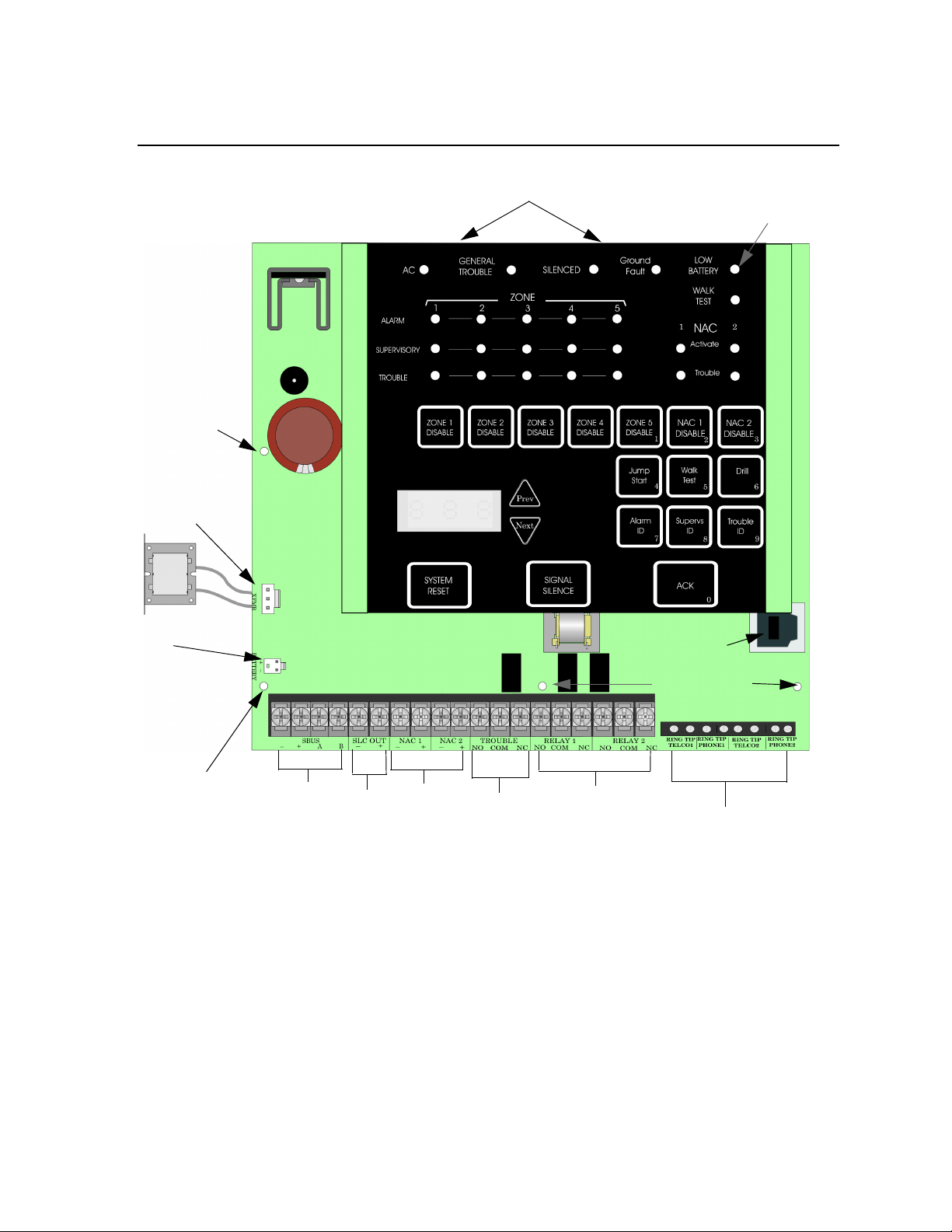
T able 3-1 list the electrical specifications for the MS-25 field wiring as well as a description of
the each individual terminal and their respective electrical rating. For location of the terminals
refer to 3.5. See also Section 4 for installation.
Table 3-1: Terminal Descriptions
Terminal
Block
TB 1 SBUS – SBUS Power 27.4 VDC 100 mA 0Ω
SLC Out – SLC Terminals 24 VDC 100 mA 0Ω
*NAC1 – Notification Appliance Circuit 24 VDC 2.0 Amp 0Ω
*NAC2 – Notification Appliance Circuit 24 VDC 2.0 Amp 0Ω
TROUBLE NO Normally open relay contact 24 VDC 2.5 A, resistive N/A
RELAY 1 NO Normally open relay contact 24 VDC 2.5 A, resistive N/A
RELAY 2 NO Normally open relay contact 24 VDC 2.5 A, resistive N/A
TB 2 TELCO 1 RING Phone Line 1 Telco Ring N/A N/A N/A
PHONE 1 RING Phone Line 1 Phone Ring
TELCO 2 RING Phone Line 2 Telco Ring
PHONE 2 RING Phone Line 2 Phone Ring
Label
Description
Group Individual V oltage Current Ohms
+
A SBUS Communication 3.3 VDC 10 mA 0Ω
B
+
+ Auxiliary power 1.0 Amp
+ Auxiliary power 1.0 Amp
COM Common terminal
NC Normally closed relay contact
COM Common terminal
NC Normally closed relay contact
COM Common terminal
NC Normally closed relay contact
TIP Phone Line 1 Telco Tip
TIP Phone Line 1 Phone Tip
TIP Phone Line 2 Telco Tip
TIP Phone Line 2 Phone Tip
Rating
Earth Ground
Fault Impedance
* Regulated for NAC circuits
* Special application when used for auxiliary power circuits.
3-2 53688
Page 23
Before You Begin Installing
1/4” spacing must
be maintained
between power
limited and Nonpower limited
wiring
3.4 Wiring Specifications
Induced noise (transfer of electrical energy from one wire to another) can interfere with
telephone communication or cause false alarms. To avoid induced noise, follow these
guidelines:
• Isolate input wiring from high current output and power wiring. Do not pull one multiconductor cable for the entire panel. Instead, separate the wiring as follows:
High voltage AC power Terminals
SLC loops Phone line circuits
Notification circuits NAC1 through NAC2
Relay circuits SBUS Wiring
• Do not pull wires from different groups through the same conduit. If you must run them
together, do so for as short a distance as possible or use shielded cable. Connect the shield
to earth ground at the panel. You must route high and low voltages separately.
• Route the wiring around the inside perimeter of the cabinet. It should not cross the circuit
board where it could induce noise into the sensitive microelectronics or pick up unwanted
RF noise from the high speed circuits. See Figure 3-1 for an example.
• High frequency noise, such as that produced by the inductive reactance of a speaker or
bell, can also be reduced by running the wire through ferrite shield beads or by wrapping it
around a ferrite toroid.
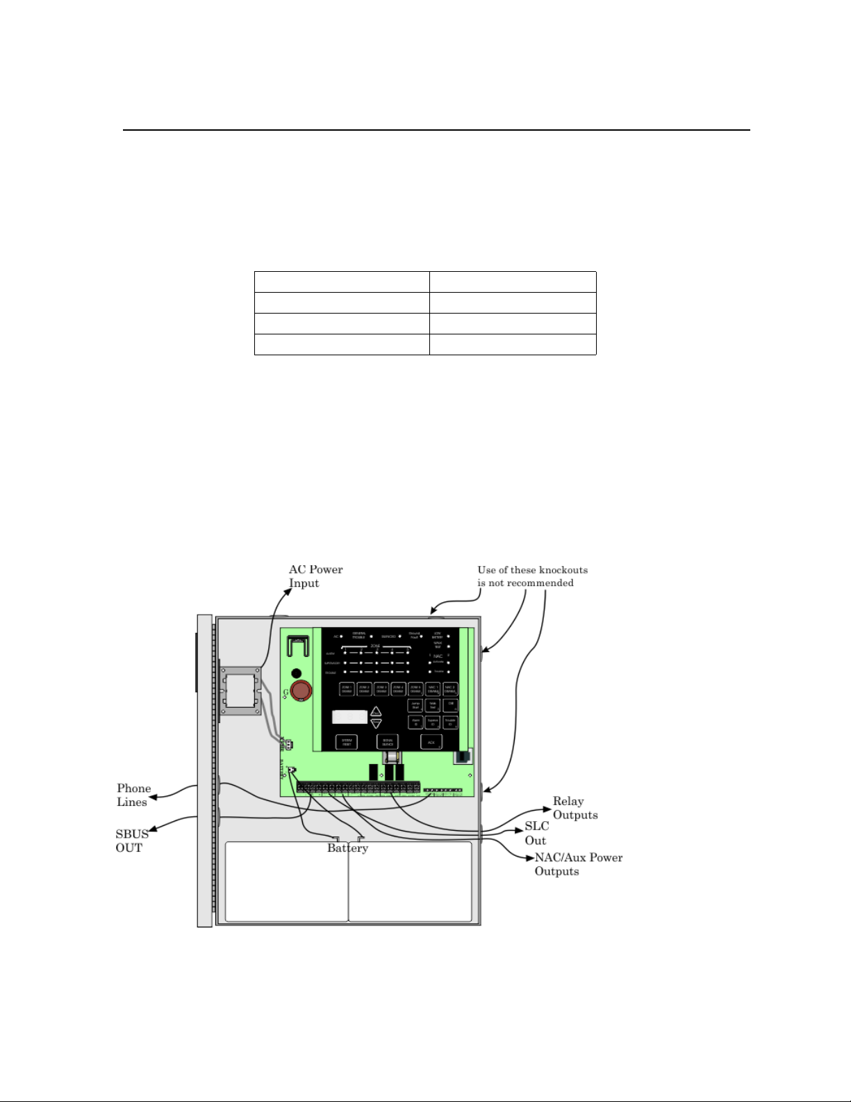
Figure 3-1 Wire Routing Example
53688 3-3
Page 24
Model MS-25 Installation and Operation Manual
Form C
Trouble Relay
On-board
Annunciator
Battery
Connector
AC Power
Input
Form C
Programmable
Relays
AC Power Input
Battery
Connector
24VDC
Ethernet
Programming Port
Mounting
screw
Location
mounting
pin
Mounting screws
Slide-In Stand-offs
SBUS
SLC Out
NAC/AUX
Power
Circuits
Phone Lines
3.5 Board Assembly Diagram
Figure 3-2 Model MS-25 Assembly
Figure 3-2 shows the MS-25 circuit board stack. If you should need to remove the control
board for repair, remove the three mounting screws which hold the control board in the
cabinet, slide out of slot from slide-in standoff. Then lift the control board off the location
mounting pin and out of the cabinet.
3-4 53688
Page 25

Before You Begin Installing
3.6 Calculating Current Draw and Standby Battery
This section is for helping you determine the current draw and standby battery requirements
(Table 3-2).
3.6.1 Worksheet Requirements
The following steps must be taken when determining MS-25 current draw and standby battery
requirements.
1. For the MS-25, the worst case current draw is listed for the panel and all addressable
devices. Fill in the number of addressable devices that will be used in the system and compute the current draw requirements for alarm and standby. Record this information in the
Current Calculation Worksheet at Line A.
2. Add up the current draw for all auxiliary devices and record in the table at Line B.
3. Add up all notification appliance loads and record in the table at Line C.
4. For notification appliance circuits and auxiliary devices not mentioned in the manual,
refer to the device manual for the current ratings.
5. Make sure that the total alarm current you calculated, including current for the panel itself,
does not exceed 2.0 A. This is the maximum alarm current for the MS-25 control panel.
If the current is above 2.0 A you will need to use a notification power expander(s) such as
the Fire-Lite FCPS-24FS6 (8) power supply to distribute the power loads so that the MS25 or the power expanders do not exceed their power rating.
6. Complete the remaining instructions in the Current Calculation Worksheet for determining
battery size requirements.
53688 3-5
Page 26
Model MS-25 Installation and Operation Manual
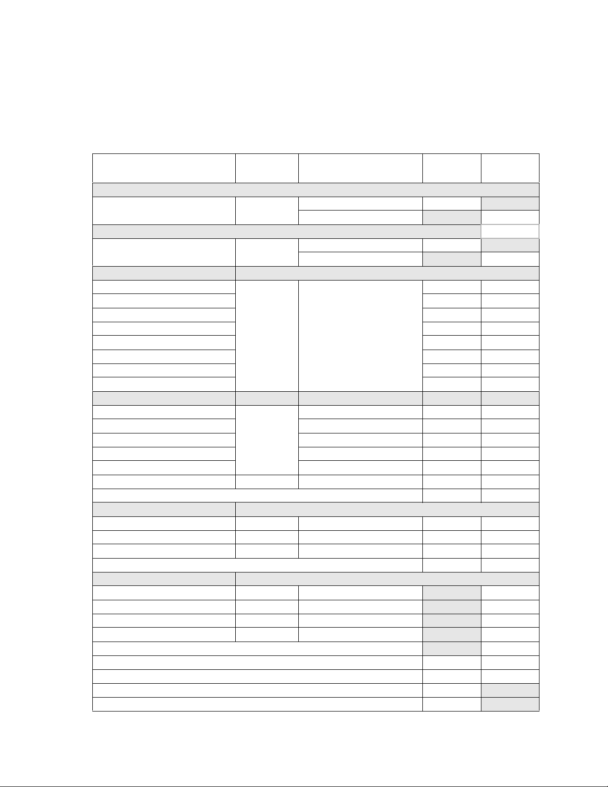
3.6.1.1 Current Draw Worksheet for MS-25 UL 864
Use Table 3-2 to determine amp-hour requirements during alarm/battery standby operation.
(Copy the page if additional space is required.) You can install up to 25 SLC devices and two
ANN-80 Remote Annunciator.
Table 3-2: Current Calculation Worksheet for SLC Devices
Device # of Devices Current per Device
For each device use this formula: This column X This column = Current per number of devices.
Fire Panel (Current draw from
battery)
Accessory Modules
ANN-80 Remote Annunicator
Addressable SLC Detectors
HFS-P
HFS-PT mA mA
HFS-D mA mA
HFS-T mA mA
SD355 mA mA
SD355T mA mA
D355PL mA mA
H355 mA mA
Addressable SLC Modules
HFS-MM
BG-12LX Standby/Alarm: 0.375 mA mA mA
HFS-MR Standby/Alarm: 0.255mA mA mA
MMF-301 Standby/Alarm: 0.375 mA mA mA
CRF-300 Standby/Alarm: 0.375 mA mA mA
I300 10 max. Standby/Alarm: 0.45 mA mA mA
A Total System Current
Auxiliary Devices Refer to devices manual for current rating.
B Auxiliary Devices Current
Notification Appliance Circuits Refer to device manual for current rating.
C Notification Appliances Current
D Total current ratings of all devices in system (line A + line B + C) mA mA
E Total current ratings converted to amperes (line D x .001): A A
F Number of standby hours (24 or 60 for NFPA 72, chapter 1, 1-5.2.5): H
G Multiply lines E and F. Total standby AH AH
1
2
(25 max.
detectors or
modules in any
combination)
(25 max.
detectors or
modules in any
combination)
Standby: 135 mA 135 mA
Alarm: 220 mA 220 mA
Standby: 37 mA mA
Alarm: 40 mA mA
Standby: 0.27 mA
Alarm: 6.5 mA
Standby/Alarm: 0.375 mA mA mA
Alarm/Standby: mA mA mA
Alarm/Standby: mA mA mA
Alarm/Standby: mA mA mA
Alarm: mA mA
Alarm: mA
Alarm: mA
Alarm: mA
Standby
Current
mA mA
Alarm
Current
mA
mA
mA
mA
3-6 53688
Page 27

Before You Begin Installing
Table 3-2: Current Calculation Worksheet for SLC Devices
Device # of Devices Current per Device
H Alarm sounding period in hours. (For example, 5 minutes = .0833 hours)
I Multiply lines E and H. Total alarm AH
J
Add lines G and I.
1. Use next size battery with capacity greater than required.
1
Total ampere hours
required
Standby
Current
Alarm
Current
H
AH
AH
53688 3-7
Page 28
Model MS-25 Installation and Operation Manual
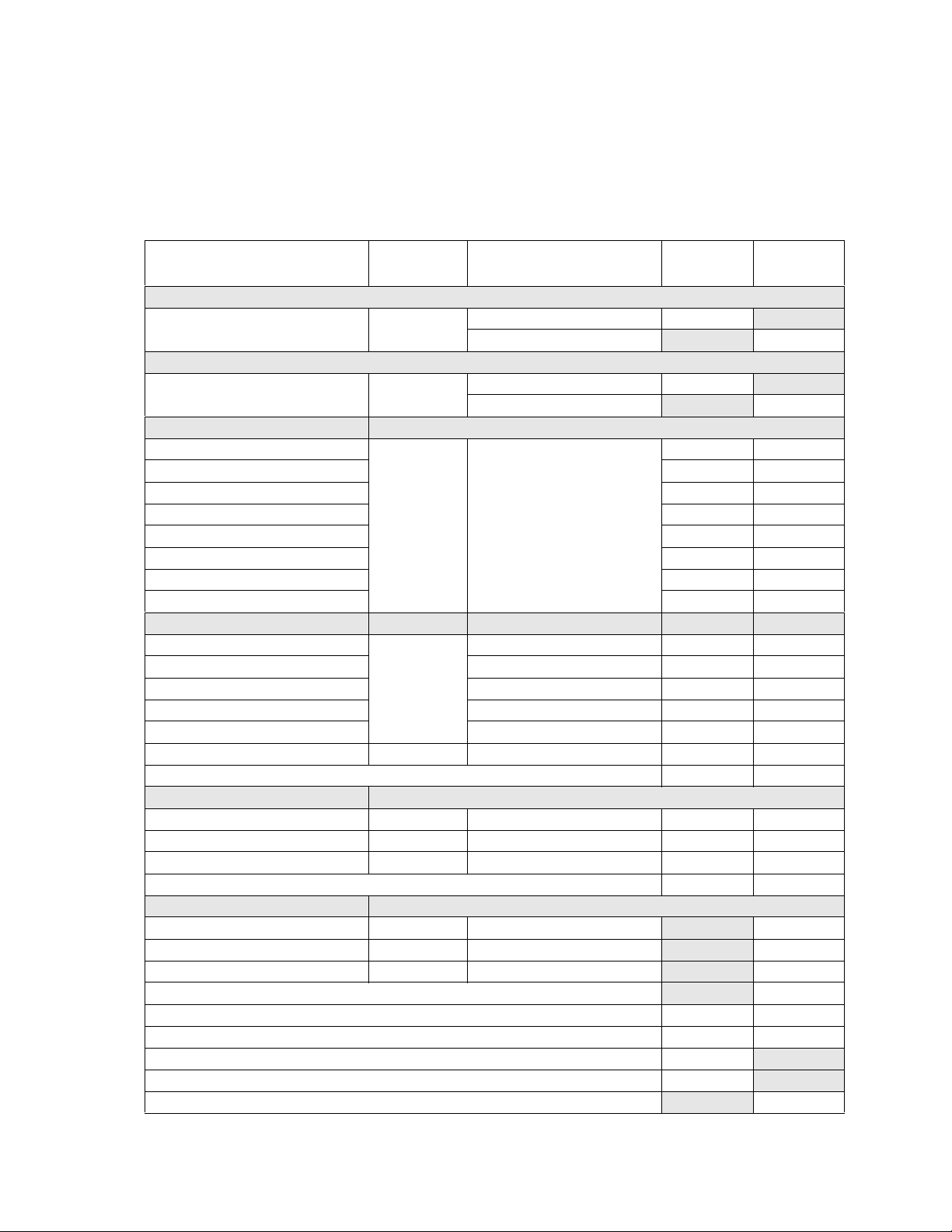
3.6.1.2 Current Draw Worksheet for MS-25C ULC
Use to determine amp-hour requirements during alarm/battery standby operation. (Copy the
page if additional space is required.) You can install up to 25 SLC devices and two ANN-80C
Remote Annunciator. The maximum battery size for ULC installations is 18 Amp/hr.
Table 3-3: Current Calculation Worksheet for Devices for ULC
Device # of Devices Current per Device
For each device use this formula: This column X This column = Current per number of devices.
Fire Panel (Current draw from
battery)
Accessory Modules
ANN-80C Remote Annunicator
Addressable SLC Detectors
HFS-PA
HFS-PTA mA mA
HFS-DA mA mA
HFS-TA mA mA
SD355A mA mA
SD355TA mA mA
D355PLA mA mA
H355A mA mA
Addressable SLC Modules
HFS-MMA
BG-12LX Standby/Alarm 0.375 mA
HFS-MRA Standby/Alarm 0.255mA mA mA
MMF-301A Standby/Alarm 0.375 mA
CRF-300A Standby/Alarm 0.375 mA
I300A 10 max Standby/Alarm 0.45 mA mA mA
A Total System Current
Auxiliary Devices Refer to devices manual for current rating.
B Auxiliary Devices Current
Notification Appliance Circuits Refer to device manual for current rating.
C Notification Appliances Current
D Total current ratings of all devices in system (line A + line B + C) mA mA
E Total current ratings converted to amperes (line D x .001): A A
F Number of standby hours (24 or 60 for NFPA 72, chapter 1, 1-5.2.5): H
G Multiply lines E and F. Total standby AH AH
H Alarm sounding period in hours. (For example, 5 minutes = .0833 hours) H
1
2
25 max.
25 max
Standby: 165 mA 165 mA
Alarm: 220 mA 220 mA
Standby: 37 mA mA
Alarm: 40 mA mA
Standby: 0.27 mA
Alarm: 6.5 mA
Standby/Alarm 0.375 mA mA mA
Alarm/Standby: mA mA mA
Alarm/Standby: mA mA mA
Alarm/Standby: mA mA mA
Alarm: mA mA
Alarm: mA
Alarm: mA
Standby
Current
mA mA
Alarm
Current
mA
mA
mA
3-8 53688
Page 29

Before You Begin Installing
Table 3-3: Current Calculation Worksheet for Devices for ULC
Device # of Devices Current per Device
I Multiply lines E and H. Total alarm AH
J
Add lines G and I.
1. Use next size battery with capacity greater than required.
1
Total ampere hours
required
Standby
Current
Alarm
Current
AH
AH
53688 3-9
Page 30

Model MS-25 Installation and Operation Manual
3.6.2 Maximum Battery Standby Load for UL 864
Table 3-4 shows the standby load calculations for the MS-25 based on 24 hours of standby.
The standby load calculations of line D in the Current Draw Calculation Worksheet must be
less than the number shown in Table 3-4 for the selected battery size, standby hour and alarm
time. The numbers below have a built in 20% derating factor for the battery amp hour
capacity.
Table 3-4: Maximum Battery Standby loads for 24 Hour Standby
Rechargeable
Battery Size
7 AH 226 mA 213 mA 206 mA
12 AH 393 mA 379 mA 372 mA
18 AH 593 mA 579 mA 572 mA
24 AH 793 mA 779 mA 772 mA
33 AH 1.09 A 1.08 A 1.07 A
24 hr Standby,
5 mins. Alarm
24 hr Standby,
15 min alarm
24 hr Standby,
20 min alarm
3.6.3 Maximum Battery Standby Load for ULC
Table 3-5 shows the ULC standby load calculations for the MS-25C based on 24 hours of
standby. The standby load calculations of line D in the Current Draw Calculation Worksheet
must be less than the number shown in Table 3-5 for the selected battery size, standby hour
and alarm time. The numbers below have a built in 40% derating factor for the battery amp
hour capacity.
Table 3-5: Maximum Battery Standby loads for ULC 24 Hour Standby
Rechargeable
Battery Size
7 AH 226 mA 213 mA 206 mA
12 AH 393 mA 379 mA 372 mA
18 AH 529 mA 515 mA 508 mA
24 hr Standby,
5 mins. Alarm
24 hr Standby,
15 min alarm
24 hr Standby,
20 min alarm
Warning
Fire-Lite does not support the use of batteries smaller than those listed in Table 3-4. If you use a battery too small
for the installation, the system could overload the battery resulting in the installation having less than the required
24 hours standby power. Use Table 3-2 to calculate the correct battery amperes/hour rating needed for your installation. It is recommended that you replace batteries every five years.
3-10 53688
Page 31

Section 4 Control Panel Installation
Caution!
To avoid the risk of electrical shock and damage to the unit, power should be OFF at the control panel while
installing or servicing.
4.1 Mounting the Control Panel Cabinet
Read the environmental specifications in Section 3.2 before mounting the MS-25 panel.
The MS-25 cabinet dimensions are:
12-3/4” W x 15-1/8” H x 3-3/8” D (32.39 cm W x 38.42 cm H x 8.57 cm D).
The MS-25 panel should be located within a secured area, where it is accessible to main drop
wiring runs and where it can be easily tested and serviced. Building occupants are responsible
for maintaining the panel should be able to hear alarms and troubles. When selecting a
location, keep in mind that the panel itself is the main source of alarm and trouble
annunciation.
When mounting on interior walls, use appropriate screw anchors in plaster. When mounting
on concrete, especially when moisture is expected, attach a piece of 3/4 inch plywood to the
concrete surface and then attach the MS-25 to the plywood. Also mount any other desired
components to the plywood.
DO NOT flush-mount the MS-25 cabinet.
4.1.1 Preventing Water Damage
Water damage to the fire system can be caused by moisture entering the cabinet through the
conduits. Conduits that are installed to enter the top of the cabinet are most likely to cause
water problems. Installers should take reasonable precautions to prevent water from entering
the cabinet. Water damage is not covered under warranty.
4.1.2 Removing the MS-25 Assembly from the Housing
If it should ever be necessary to remove the control panel assembly from the cabinet for
repair, do so by removing the screws that hold the control panel in to the cabinet. Do not
attempt to disassemble the circuit boards.
53688 4-1
Page 32

Model MS-25 Installation and Operation Manual
Dead Front
Panel
4.1.3 Dead Front Installation and removal
This section provides instructions to install and or remove the dead front for the control panel
cabinet.
4.1.3.1 Installing the Dead Front
Follow these steps to properly install the dead front panel into the control panel cabinet.
1. Remove the top two annunciator screws, do not discard them they will be reused. See
Figure 4-1 for annunciator screw location.
2. Set the dead front into the cabinet as shown in Figure 4-1.
3. Reinsert the two annunciator screws as shown in Figure 4-1.
Figure 4-1 Dead Front Installation and Removal
4-2 53688
Page 33

Control Panel Installation
4.1.3.2 Dead Front Removal
Follow these steps to properly remove the dead front panel from the control panel cabinet.
1. Remove the two annunciator screws, do not discard them. See Figure 4-1.
2. Tilt the dead front forward to clear the top of the cabinet and left the dead front out of the
cabinet. See Figure 4-1.
3. Reinsert the two annunciator screws. See Figure 4-1.
53688 4-3
Page 34

Model MS-25 Installation and Operation Manual
Ground
To AC
Supervised
AC
Connection
4.2 AC Power Connection
4.2.1 AC Power Connection for UL 864 applications
At installation, connect the AC terminals to the power source as shown in Figure 4-2. It may
be necessary for a professional electrician to make this connection. Connect black and white
wires from transformer to 120V power . Connect ground wire from 120V power to screw
labeled G on the MS-25 circuit board.
The AC power input is rated at 120 VAC, 60 Hz, 1.5A for MS-25 and 230 VAC, 50/60Hz,
.75A for MS-25E.
Figure 4-2 120/230 VAC Power Connection
4-4 53688
Page 35

Control Panel Installation
4.2.2 AC Power Connection for Canadian Applications
For Canadian applications, an AC terminal block is supplied standard with the MS-25C. The
AC terminal block is factory installed on the left of the circuit board chassis as shown in
Figure 4-3.
Figure 4-3 AC terminal Block Connections
53688 4-5
Page 36

Model MS-25 Installation and Operation Manual
Red
Battery Jumper
(P/N 140694)
Shippe d With Pa ne l
Black
Supervised
Battery 2Battery 1
12V Battery
12V Battery
Fire-Lite
PN BAT-1270
4.3 Battery Connection
The control panel battery charge capacity is 7.0 to 33 AH or 18 AH for ULC installations. The
main control cabinet can house batteries up to 7 AH, larger capacity batteries can be housed in
a Remote Battery Box (P/N BB-26 or BB-55F). Use 12V batteries of the same AH rating.
Determine the correct AH rating as per your current load calculation (see Section 3.6).
Maximum charging current for batteries is 3.1A @ 27 VDC.
Wire batteries in series to produce a 24-volt equivalent. Do not parallel batteries to increase
the AH rating.
The following steps and diagram explain how to connect the batteries.
1. Connect the black wire from the control panel negative (–) battery terminal to the negative
(–) side of Battery #2.
2. Connect the jumper wire provided (P/N 140694) from the positive (+) side of Battery #2
to the (–) negative side of Battery #1.
3. Connect the red wire from the control panel positive (+) terminal to the positive (+) side of
Battery #1.
4-6 53688
Figure 4-4 Battery Connection
Page 37

Control Panel Installation
4.4 SBUS Wiring
This section contains information on calculating SBUS wire distances and the types of wiring
configurations (Class B).
4.4.1 Calculating Wiring distance for SBUS modules
The following instructions will guide you in determining the type of wire and the maximum
wiring distance that can be used with control panel SBUS accessory modules.
To calculate the wire gauge that must be used to connect SBUS modules to the control panel,
it is necessary to calculate the total worst case current draw for all modules on a single 4conductor bus. The total worst case current draw is calculated by adding the individual worst
case currents for each module. The individual worst case values are shown in the table below.
Note: Total worst case current draw on a single SBUS cannot exceed 500 mA.
Model Number Worst Case Current Draw
MS-25 Remote Fire Annunciator .04 amps
After calculating the total worst case current draw, Table 4-1 specifies the maximum distance
the modules can be located from the panel on a single wire run. The table insures 6.0 volts of
line drop maximum. In general, the wire length is limited by resistance, but for heavier wire
gauges, capacitance is the limiting factor.
These cases are marked in the chart with an asterisk (*). Maximum length can never be more
than 6,000 feet, regardless of gauge used. (The formula used to generate this chart is shown in
the note below).
Table 4-1: Wire Distance Per Wire Gauge Using Copper Wire
Wiring Distance: SBUS Modules to Panel
Total W orst Case
Current Draw (amps)
0.100 1852 ft. 4688 ft. * 6000 ft. * 6000 ft.
0.200 926 ft. 2344 ft. 3731 ft. 5906 ft.
0.300 617 ft. 1563 ft. 2488 ft. 3937 ft.
0.400 463 ft. 1172 ft. 1866 ft. 2953 ft.
0.500 370 ft. 938 ft. 1493 ft. 2362 ft.
0.600 309 ft. 781 ft. 1244 ft. 1969 ft.
0.700 265 ft. 670 ft. 1066 ft. 1687 ft.
0.800 231 ft. 586 ft. 933 ft. 1476 ft.
0.900 206 ft. 521 ft. 829 ft. 1312 ft.
1.000 (Max) 185 ft. 469 ft. 746 ft. 1181 ft.
22 Gauge 18 Gauge 16 Gauge 14 Gauge
53688 4-7
Page 38

Model MS-25 Installation and Operation Manual
Note: The following formulas were used to generate the wire distance chart:
Maximum Resistance (Ohms) = 6.0 Volts
Total Worst Case Current Draw (amps)
Maximum Wire Length (Feet) =
(6000 feet maximum)
where: Rpu = Ohms per 1000 feet for various wire gauges (see table below)
Table 4-2: Typical Wire Resistance per 1000 ft. using Copper Wire
Wire Gauge Ohms per 1000 feet (Rpu)
22 16.2
18 6.4
16 4.02
14 2.54
Maximum Resistance (Ohms) * 500
Rpu
Wiring Distance calculation example:
Suppose a system is configured with the following SBUS modules:
1 - Module MS-25 Fire Annunciator
The total worst case current is calculated as follows:
MS-25 Current Draw = 1 x .04 amps = .04 amps
Total Worst Case Current Draw = .04 amps
Using this value, and referring to the Wiring Distance table, it can be found that the available
options are:
1852 feet maximum using 22 Gauge wire
4688 feet maximum using 18 Gauge wire
6000 feet maximum using 16 Gauge wire
6000 feet maximum using 14 Gauge wire
4-8 53688
Page 39

4.4.2 Wiring Configurations
Supervised
Power Limited
ANN-80
Figure 4-5 illustrates Class B configuration.
Control Panel Installation
Figure 4-5 SBUS Class B Wiring
53688 4-9
Page 40

Model MS-25 Installation and Operation Manual
4.5 ANN-80 Remote Annunciator Installation
The optional Model ANN-80 (red) and ANN-80-W (white) Remote Annunciator is shown in
Figure 4-6.
Figure 4-6 Model ANN-80 Remote Annunciator, Front View
ANN-80 installation involves the following steps:
1. Make sure power is off at the panel.
2. Mount the ANN-80 in the desired location (see Section 4.5.1).
3. Connect the ANN-80 to the panel (see Section 4.6).
4. Use the DIP switches on the back of the ANN-80 to assign an ID# to the ANN-80 (see
Section 4.7.1).
5. The new ANN-80 module must be added to the system through programming.
JumpStart will add the module automatically (see Section 6.1). You can also add it manually (see Section 7.3.2). Select a name, if desired (see Section 7.3.1.1).
4-10 53688
Page 41

Control Panel Installation
Back Box
Inside Cover
LCD Display
4.5.1 Mounting the ANN-80
This section of the manual describes mounting the remote annunciator. Figure 4-7 shows the
parts of the annunciator.
Figure 4-7 ANN-80 Annunciator Parts
The ANN-80 Series plastic enclosures can be surface or semi-flush mounted in a single,
double or 4” square electrical box.
To mount the ANN-80 Series enclosure:
1. Open the ANN-80 Series cover by turning the key switch counterclockwise to the ON
(Unlocked) position.
2. Push in the snap latch tab located on the right side while pulling the cover open.
3. Pull wire through 7/8” hole in backplate and feed through wire channel to lower left corner of backplate before routing to terminal block.
4. The cover must remain attached to the backplate while mounting the annunciator to the
electrical box/ wall. The cover cannot be reattached or removed after the annunciator has
been mounted.
5. Surface or Semi-flush mount the ANN-80 to a single, double or 4" square electrical box.
The ANN-SB80KIT(-R/-B/-W) is an available kit that contains two plastic backboxes that
can be used to surface mount the ANN-80.
53688 4-11
Page 42

Model MS-25 Installation and Operation Manual
Supervised
Power Limited
4.6 Model ANN-80 Connection to the Panel
Connect the ANN-80 to the panel as shown in Figure 4-8.
Figure 4-8 Model ANN-80 Connection to the Panel
4-12 53688
Page 43

Control Panel Installation
ID Number
(Address)
(not valid) 00
01
02
DIP Switch
4.7 Configuring Module
This section describes how to configure the ANN-80 Annunciator that has been added to the
system. Each SBUS device requires a unique address. ANN-80 Series DIP switch S21 is used
to set the address. This address will be displayed on the LCD display as the Station ID
number.
4.7.1 Assigning Module IDs
When installing the ANN-80 you must use the DIP switches on the module to assign an ID# to
the module. A maximum of 2 devices can be connected to the FACP SBUS communication
circuit. The SBUS device address needs to be set to 01or 02.
Note: Note that 00 is not a valid address.
Figure 4-9 shows the DIP switch positions and their correlation to a numerical ID.
Figure 4-9 DIP switch settings
53688 4-13
Page 44

Model MS-25 Installation and Operation Manual
Use Minimum of 26
AWG Telephone
Line cord
4.8 Telephone Connection
Connect the telephone lines as shown in Figure 4-10. The Model 7860 phone cord is available
from Fire-Lite for this purpose.
Figure 4-10 Connection of Telephone Lines
4-14 53688
Page 45

Control Panel Installation
4.9 Notification Appliance/Auxiliary Power Circuits
The two outputs of the MS-25 can be programmed to be used as NACs or as Aux power.
This section of the manual explains how to install conventional notification appliances and
how these terminals can be used for auxiliary power.
4.9.1 Conventional Notification Appliance Circuit
The MS-25 supports Class B (Style Y) configurations for notification appliance applications.
You must use an appliance from the list of compatible appliances in the Appendix A at the
back of this manual. Each circuit can source up to 2.0A. (total current for the system must not
exceed 2.0A)
To install a Class B notification appliance circuit:
1. Wire Class B Notification appliances as shown in Figure 4-11.
2. Configure the circuit through programming.
Figure 4-11 Class B Notification Appliance Circuit Wiring
53688 4-15
Page 46

Model MS-25 Installation and Operation Manual
Non-Supervised
Power Limited
+
–
Special
Application
DC Circuit
4.9.2 Auxiliary Power Installation
NAC Circuits 1 and 2 on the control panel can be used as auxiliary power circuits. The three
types of auxiliary power available are:
• Door Holder (see section 4.9.2.1)
• Constant (see section 4.9.2.2)
• Resettable Power (see section 4.9.2.3)
Auxiliary power circuits are power limited. Each circuit can source up to 1.0A (total current
for system must not exceed 2.0A).
To install an auxiliary power circuit:
1. Wire the NAC circuit(s) that will be used for auxiliary power . See 3.5 for location of NAC
circuits.
2. Configure the auxiliary power output through programming.
4.9.2.1 Door Holder Power
Door holder power is intended for fire door applications. When there are no alarms in the
system and the panel has AC power, door holder circuits have 24 volt power present at their
terminals. Any alarm will cause power to disconnect. Power will be re-applied when the
system is reset. If AC power is off for more than 15 seconds, the auxiliary door holder power
will be disconnected to conserve the battery backup. When AC power is restored, power is
immediately restored to the door holder circuits.
Figure 4-12 Example of an Auxiliary Power For Door Holder
Use a UL listed door holder see list from Appendix A-3, for this application.
4-16 53688
Page 47

Control Panel Installation
4.9.2.2 Constant Power
Use constant power for applications that require a constant auxiliary power source. Power is
always present at Constant circuits.
4.9.2.3 Resettable Power
Resettable power is typically used to power beam detectors, flame detectors and conventional
4-wire smoke detectors. For circuits selected as Resettable, 24 volt power is always present at
the terminals unless a system reset occurs. If a system reset occurs, power is disconnected
from the terminals for 30 seconds, then re-applied.
53688 4-17
Page 48

Model MS-25 Installation and Operation Manual
4.10 On-Board Relays (Conventional, Power Limited)
The control panel has two built-in programmable relays and a built-in trouble relay. All relays
are Form C rated at 2.5 A @ 24 VDC Resistive.
4.10.1 Common Trouble Relay
The control panel has a dedicated Form C trouble relay built into terminals labeled
TROUBLE. The relay provides a normally open and a normally closed contact. The trouble
relay will deactivate under any trouble condition. Form C rated at 2.5 A @ 24 VDC Resistive.
Note: The N.C. contact is the relay contact that is closed when the panel has power and there are no alarm or
trouble conditions.
4.10.2 Programmable Relays
The control panel has two Form C programmable relays built into terminals labeled RELAY 1
or RELAY 2. Each relay provides a normally open and a normally closed contact.
To configure one or two programmable relays, follow these steps.
1. Wire Relay 1 and/or Relay 2 as needed for your application. See 4.10.1 for the location of
the relay terminals.
2. Default programming causes Relay 1 to activate for any supervisory. Relay 2 will activate
for any alarm. For relay applications that require different behavior see Section 6.
4-18 53688
Page 49

Control Panel Installation
4.11 Remote Station Applications
4.11.1 City Box Connection Using the 5220 Module
This section describes how to connect the control panel to a municipal fire alarm box or “city
box” as required by NFPA 72 Auxiliary Protected Fire Alarm systems for fire alarm service.
The city (master) box is an enclosure that contains a manually operated transmitter used to
send an alarm to the municipal communication center which houses the central operating part
of the fire alarm system.
City Box Standby Current: 0 (Notification supervision current
accounted for in control panel draw.)
Alarm Current: 1 Amp for 1 second
Max Voltage: 24 VDC
The maximum coil and wire resistance (combined) must not exceed 30 ohms.
To install the 5220 for city box connection:
1. Use one of the knockouts on the right side of the control panel to connect the 5220 using a
short piece of conduit (must not exceed 20 feet in length).
2. Wire the 5220 to the control panel as shown in Figure 4-13. This drawing also shows how
to connect the city box coil to terminals 3 and 4 on the 5220. Do not install an EOL resistor in the terminals of the NAC circuit used for this application.
3. Connect earth ground wire to the 5220 chassis with mounting screw.
4. Program NAC1 as auxiliary and power constant on. Program NAC2 as a non-silencing,
constant on notification circuit.
53688 4-19
Page 50

Model MS-25 Installation and Operation Manual
Note:
NAC Circuit 2 Used
as an Example.
Either NAC Circuit Can
Be Used.
Supervised for Opens
and Ground faults
only Non-Power
Limited
It is not possible to reset the remote indication until you clear the condition and reset the
control panel.
4-20 53688
Figure 4-13 City Box Connection
Page 51

Control Panel Installation
4.11.2 NFPA 72 Polarity Reversal
4.11.2.1 Alarm, Supervisory and Trouble Reverse Polarity Outputs
Three HFS-MR or CRF-300 modules are required to independently report alarm, supervisory
and trouble. SLC addresses 141, 143, and 147 must be used as shown in Figure 4-14.
Figure 4-14 Reverse Polarity output wiring
53688 4-21
Page 52

Model MS-25 Installation and Operation Manual
4-22 53688
Page 53

Section 5 SLC Device Installation
Cautions!
To avoid the risk of electrical shock and damage to the unit, power should be OFF at the
control panel while installing or servicing.
5.1 List of SLC Devices
The following SLC devices can be used with the control panel. See the device installation
instructions for more information. (packaged with the device)
Part Number Model Name/Description Install Sheet PN
HFS-P, HFS-PA, SD355, SD355A Photoelectric smoke detector
HFS-PT, HFS-PTA, SD355T, SD355TA Photoelectric smoke detector with thermal (135°F)
HFS-D, HFS-DA, D350PL, D350PLA Photoelectric duct smoke detector with extended air speed range I56-3488-00, I56-1975-00
HFS-T, HFS-TA, H355, H355A Fixed temperature thermal detector (135°F) I56-3485-00, I56-1972-01
BG-12LX Addressable dual action pull station 51094
HFS-MM, HFS-MMA, MMF-301,
MMF301A
HFS-MR, HFS-MRA, CRF-300, CRF-
300A
I300, I300A Addressable Isolator Module I56-1381-002
Mini monitor module I56-3487-000, I56-3654-00
Addressable relay module I56-3486-000, I56-3651-00
I56-3483-00, I56-3660-00
5.2 Maximum Number of Devices
• A MS-25 system supports a maximum of 25 SLC detectors and modules, in any
combination.
53688 5-1
Page 54

Model MS-25 Installation and Operation Manual
5.3 Wiring Requirements for SLC Devices
The following information applies to all SLC devices. Refer to the section that describes the
type of device you are installing for details.
5.3.1 Wiring SLC in Style 4 (Class B) Configuration
No special wire is required for addressable loops. The wire can be untwisted, unshielded, solid
or stranded as long as it meets the National Electric Code 760-121 requirements for power
limited fire protective signaling cables. Wire distances are computed using copper wire.
Maximum wiring resistance is 40 ohms to the farthest SLC device.
Maximum loop length depends on the wire gauge.
All SLC wiring is Supervised, and Power-limited.
Table 5-1 Maximum wiring distance for SLC devices
Wire Gauge
22 AWG 1200 feet
18 AWG 3100 feet
16 AWG 4900 feet
14 AWG 7900 feet
12 AWG 10,000 feet
Max. Distance for SLC
devices
5-2 53688
Page 55

SLC Device Installation
The following figures show how length is determined for out and back tap and T-Tap style
wiring.
Figure 5-1 Calculating wire run length for a simple out and back
53688 5-3
Page 56

Model MS-25 Installation and Operation Manual
When using T-taps, the total length of all taps and the main bus must not exceed 40,000 feet.
This requirement must be met in addition to the maximum distance requirements for the
various wire gauges.
Figure 5-2 Calculating Wire Run Length for a T-tap
5-4 53688
Page 57

SLC Device Installation
Supervised
Power limited
5.4 Wiring SLC Detectors
This section describes how to install heat and smoke detectors. All detectors ship with
installation instructions. Refer to the detector’s installation instructions for more detailed
information.
This information applies to the following models:
• HFS-P, HFS-PA, SD355 Photoelectric Smoke Detector
• HFS-PT, HFS-PTA, SD355T Photoelectric Smoke Detector with Thermal
• HFS-D, HFS-DA, D350PL Photoelectric Duct Detector
• HFS-T, HFS-TA, H355 Fixed Temperature Detector
To wire detectors:
1. Wire device bases as shown in Figure 5-3.
2. Set the address for each device as described in Section 5.5.
Figure 5-3 Heat and Smoke Detector Connection to the Panel.
53688 5-5
Page 58

Model MS-25 Installation and Operation Manual
All dials labeled for ONES
or TENS position
Example 1: Device Set to 35
Example 2: Device set to 105
5.5 Addressing SLC Devices
All SLC devices are addressed using the two rotary dials that appear on the device board. Use
the ONES rotary dial to set the ones place in a one or two digit number, and use the TENS
rotary dial to set the tens place in a two digit number.
Example 1: To select device address 35, turn the ONES rotary dial to 5 and the TENS rotary
dial to 3 as shown in Figure 5-4.
Example 2: T o select device address 105, turn the ONES rotary dial to 5 and the TENS rotary
dial to 10 as show in Figure 5-4.
Figure 5-4 SLC Device Addressing Using Rotary Dials
5-6 53688
Page 59

Section 6 Programming
This section of the manual describes how to change the control panel programming options
from the built-in web page of the control panel. All options described in this section are edited
via the panel’s built in web page
Important!
Before any customized programming is done, JumpStart should be run first. After JumpStart
is run, thoroughly test the system. The reason the system should be tested after JumpStart is
because JumpStart automatically programs the system, searching for and configuring all
SLC devices and SBUS annunciators it finds. JumpStart allows you to confirm the integrity
of the installation prior to performing any custom programming. After determining that the
hardware is properly installed, custom programming can be performed. Refer to Section 6.
6.1 UL 864 Programming Requirements
Table 6-1: Standards in Requirements for Control Units and Accessories
NOTICE TO USERS, INSTALLERS, AUTHORITIES HAVING JURISDICTION, AND
OTHER INVOLVED PARTIES: This product incorporates field programmable software. In
order for the product to comply with the requirements in the Standard for Control Units and
Accessories for Fire Alarm Systems, UL 864, certain programming features or options must be
limited to specific values or not used at all as indicated below.
Programming Option Menu Item
System Options Low AC Report Delay Yes 0–30 hours 1–3
Zone Options Supervisory Yes Latching/Non Latching
Zone Options Waterflow Yes Latching/Non Latching
System Options Alarm Verification Yes 1-250 seconds 60-250 seconds
Dialer Phone line Programming
option
Line Monitor Enabled Yes Y/N Y*
Permitted in
UL 864 (Y/N)
Possible
Settings
Settings Permitted in
UL 864
*Only needs to be enabled if using the DACT.
53688 6-1
Page 60

Model MS-25 Installation and Operation Manual
6.2 Control Panel Programming
The MS-25 is an addressable control panel that has the characteristics of a 5 zone
conventional fire alarm control panel.
6.3 Default Control Panel Configuration.
The panel ships from the factory in a defaulted configuration that may allow the installer to
use the panel without doing any custom programming.
6.3.1 Default Mapping of SLC Inputs to Outputs
The panel mapping configuration for the MS-25 is fixed with regards to SLC addresses, zone
assignments and output points. The relationship between input points and output points
follows the rules defined in 6.3.2 below. For input points, the SLC address determines the
zone assignment and alarm characteristics. For output points, the SLC address determines the
output function for the point.
6.3.2 Mapping of SLC Inputs to Outputs.
Table 6-2: Input Points
INPUT POINTS
Zone Input Point Types Function Qty
Zone 1 HFS-P, HFS-PT, HFS-D,
HFS-T, SD355, SD355T,
D355PL, H355, MMF-301,
BG-12LX, HFS-MM
Zone 2 HFS-P, HFS-PT, HFS-D,
HFS-T, SD355, SD355T,
D355PL, H355, MMF-301,
BG-12LX, HFS-MM
Zone 3 HFS-P, HFS-PT, HFS-D,
HFS-T, SD355, SD355T,
D355PL, H355, MMF-301,
BG-12LX, HFS-MM
Zone 4 HFS-P, HFS-PT, HFS-D,
HFS-T, SD355, SD355T,
D355PL, H355, MMF-301,
BG-12LX, HFS-MM
Zone 5 HFS-P, HFS-PT, HFS-D,
HFS-T, SD355, SD355T,
D355PL, H355, MMF-301,
BG-12LX, HFS-MM
Alarm 15 1 15 Alarm Zone 1
Supervisory 5 16 20 Supervisory Zone 1
Alarm 15 21 35 Alarm Zone 2
Supervisory 5 36 40 Supervisory Zone 2
Alarm 15 41 55 Alarm Zone 3
Supervisory 5 56 60 Supervisory Zone 3
Alarm 15 61 75 Alarm Zone 4
Supervisory 5 76 80 Supervisory Zone 4
Alarm 15 81 95 Alarm Zone 5
Supervisory 5 96 100 Supervisory Zone 5
Start
SLC ID
End SLC
ID
Description
6-2 53688
Page 61

Table 6-3: Output Points
OUTPUT POINTS
Programming
Group Output Point Type Qty
OPG 1 HFS-MR, CRF-300, CRF-300A 2 111 112 Zone 1 Alarm
OPG 2 HFS-MR, CRF-300, CRF-300A 2 113 114 Zone 2 Alarm
OPG 3 HFS-MR, CRF-300, CRF-300A 2 115 116 Zone 3 Alarm
OPG 4 HFS-MR, CRF-300, CRF-300A 2 117 118 Zone 4 Alarm
OPG 5 HFS-MR, CRF-300,CRF-300A 2 119 120 Zone 5 Alarm
OPG 6 HFS-MR, CRF-300, CRF-300A 2 121 122 Zone 1 Supervisory
OPG 7 HFS-MR, CRF-300, CRF-300A 2 123 124 Zone 2 Supervisory
OPG 8 HFS-MR, CRF-300, CRF-300A 2 125 126 Zone 3 Supervisory
OPG 9 HFS-MR, CRF-300, CRF-300A 2 127 128 Zone 4 Supervisory
OPG 10 HFS-MR, CRF-300, CRF-300A 2 129 130 Zone 5 Supervisory
OPG 11 HFS-MR, CRF-300, CRF-300A 2 131 132 Zone 1 Trouble
OPG 12 HFS-MR, CRF-300, CRF-300A 2 133 134 Zone 2 Trouble
OPG 13 HFS-MR, CRF-300, CRF-300A 2 135 136 Zone 3 Trouble
OPG 14 HFS-MR, CRF-300, CRF-300A 2 137 138 Zone 4 Trouble
OPG 15 HFS-MR, CRF-300, CRF-300A 2 139 140 Zone 5 Trouble
OPG 16 HFS-MR, CRF-300, CRF-300A 2 141 142 General Alarm
OPG 17 HFS-MR, CRF-300, CRF-300A 2 143 144 General Supervisory
OPG 18 HFS-MR, CRF-300, CRF-300A 2 145 146 General Zone Trouble
OPG 19 HFS-MR, CRF-300, CRF-300A 2 147 148 General Trouble
OPG 20 HFS-MR, CRF-300, CRF-300A 2 149 150 Alarm Silenced
OPG 21 HFS-MR, CRF-300, CRF-300A 2 151 152 Trouble Silenced
OPG 22 HFS-MR, CRF-300, CRF-300A 2 153 154 AC Loss
OPG 23 HFS-MR, CRF-300, CRF-300A 2 155 156 Resettable Aux Relay
OPG 24 HFS-MR, CRF-300, CRF-300A 2 157 158 Aux Door Holder
Start SLC IDEnd SLC
ID
Output Activates For
Table 6-2 shows that any input SLC device with an address set within the range 1-15 will be
assigned to zone 1 as an alarm input type. An SLC output relay point assigned to address 111
or 112 will activate for an alarm in zone 1.
6.3.3 Default Mapping for the 2 built-in Notification
Circuits.
There are 2 built-in notification circuits (NAC 1 and NAC 2). They are both defaulted to
activate when any of the 5 zones are in alarm. When active, NAC 1 and NAC 2 will sound the
System Sensor synchronization pattern. To change the behavior of the default mapping of
these circuits refer to Section 6.5.
53688 6-3
Page 62

Model MS-25 Installation and Operation Manual
6.3.4 Maximum SLC address point count
The MS-25 control panel supports a maximum of 25 SLC points to be used within the 159
point address range. The points can be all inputs, all outputs or any combination of inputs and
output points. When more than 25 SLC devices are added to the control panel, any excess
points will indicate a trouble and not be recognized by the panel.
6.3.5 Installer Code
The installer code is factory programmed as 123456. The installer code is required to learn
and remember which SLC devices are connected to the panel. The installer code can be
changed when a PC is used to modify the default programming options.
6.4 JumpStart Auto Programming
Once the physical installation of SLC devices is finished, the panel will need to learn which
SLC devices and SBUS annunciators are present.
IMPORTANT!
There is no limit to how often you can run JumpStart. Each time you run this
process it starts fresh and does not remember previously installed devices
that are no longer present.
To run JumpStart:
1. Press and hold the “JumpStart” key,
2. Press the installer code after PIN is displayed.
3. During JumpStart, the panel will briefly light up all LEDs and then display “SLC Prg” on
the 7 segment display.
4. When complete the display will be off and programming is complete.
If changes are required that affect address settings for the SLC devices, device types or
number of SLC devices installed you will need to repeat JumpStart to re-learn which devices
are supposed to be present on the system.
6-4 53688
Page 63

Programming
6.5 Modifying Panel Programming using a PC
6.5.1 Connecting the panel to a PC
Modifications to the default panel programming can only be done using the embedded web
server of the control panel. There are two ways to connect to the panel for the purpose of
programming. It can be connected through a DHCP (Dynamic Host Configuration Protocol)
router or it can also be plugged in using a Standard CAT5e Ethernet cable without a router.
Both methods of connecting the panel to the PC are for local connection only.
By default, the panel is configured to search for a DHCP server. If there is a DHCP server
present, the panel receives the IP configuration offered by the DHCP server and displays the
IP address on the seven segment display.
If the panel is connected to a PC without a router, it assigns itself a default class B IP address
of the format (169.254.X.X). Each panel will have a unique IP address and it will also be
displayed on the 7 segment display. When direct connected, it will normally take about 40
seconds to display the IP address. The panel displays “IP” while the IP address is being
determined during this 40 second search period.
A PC with the Windows operating system may take up to 1 minute to fallback to the APIPA
(Automatic Private IP Addressing) which enables the PC to communicate to the panel.
Whether using either the PC direct connect or the PC connected to the panel via DHCP router,
you are ready to view and edit the panel programming options once the panel shows the IP
address on the seven segment display.
The embedded web page programming tool is accessed by typing in the panel IP address in a
web browser . MS Internet explorer 6 and Mozilla Firefox 3.0.5 are the only two web browsers
tested and recommended.
53688 6-5
Page 64

Model MS-25 Installation and Operation Manual
6.6 Panel Programming Options
All customized programming options for the MS-25 control panel are described in this section
and are available to be edited using the embedded web server of the control panel.
6.6.1 System Options
6.6.1.1 Synchronized Strobes Active When Horns Silenced
The default configuration for this option is No. If set to Yes, strobes will remain on when
horns are silenced until a panel reset is issued.
6.6.1.2 Silence/Reset Inhibit Enabled
The default configuration for this option is NO. If set to Yes, Pressing either Reset or Silence
Buttons will be ignored for the duration of the delay (set to 30 seconds). The inhibit feature
delay is only active for the first alarm/supervisory signal.
6.6.1.3 Water Flow Delay
The water flow delay is a debounce time that is generally used to help reduce false alarms
during brief periods of water pressure fluctuation in a water riser. The default setting is 1
second which is the minimum debounce time. You can set the water flow delay within the
range 1-90 seconds.
6.6.1.4 Installer Code (User ID)
This is the password used to lock the list of SLC devices found during the JumpStart auto
learn process. It is defaulted to 123456 and can be changed to any 4 to 8 digit number .
6.6.1.5 Alarm Verification Time
Alarm verification is an optional false alarm prevention feature for smoke detectors that
verifies an alarm condition by resetting the smoke detector . The alarm verification time can be
set within the range of 1-250 seconds. For UL 864 installations this option must be greater
than 59 seconds. The default setting is 60 seconds.
6.6.1.6 Auto Test
Enter the hour/minutes (in 24 hour format) that you desire the control panel to send the
automatic test report.
6.6.1.7 Low AC Report Delay
This option determines the number of delay hours before a loss of AC is reported to the
central station. It is defaulted to 3 hours and must be within the range 0-30 hours. For U.L.
864 installation this option must be set within the range 1-3 hours.
6-6 53688
Page 65

Programming
6.6.1.8 Walk Test Reporting
The default configuration for this option is No. If set to Yes, the panel generates a TEST report
to the central station when the walk test begins. During a walk test, the panel’s normal fire
alarm function is completely disabled, placing the panel in a local trouble condition. All zones
respond as 1-Count zones (respond when a single detector is in alarm) during a walk test.
Each alarm initiated during the walk test will be reported.
6.6.1.9 Walk Test duration
Enter the amount of time, in minutes, for the walk test duration. When the programmed
amount of time expires, the Walk Test will end automatically.
6.6.1.10 Walk Test NAC Time out
Enter the amount of time, in seconds, for the walk test NAC active duration. During a walk
test alarm activation, the NACs will automatically deactivate after the programmed amount of
time expires.
6.6.1.11 Clock Source
The panel’s AC line frequency is selectable for 60 Hz, 50 Hz, or Internal Clock Source. AC
frequency feature dictates how the control panel will calculate time based on the AC line
frequency used in the installation site. The “Internal Clock” option can be used in areas where
the AC line frequency is not dependable and you want the panel to calculate time from the
internal crystal. The internal crystal is not as accurate as the AC power source. The panel
defaults to the 60 HZ selection.
6.6.1.12 Auto Daylight Savings Time
Select this feature to “Yes” if you want the panel to automatically adjust the clock to track
with daylight savings time.
6.6.1.13 Remote Annunciator
Select this feature to “Yes” if a ANN-80 Remote Annunciator is to be used. A customized
banner can also be added to the Remote Annunciator . The Remote Annunciator allows for the
top 2 lines to be programmed as a custom banner.
53688 6-7
Page 66

Model MS-25 Installation and Operation Manual
6.6.2 Zone Programming
6.6.2.1 SLC Addresses Within Each Zone
Each zone has 15 alarm SLC addresses and 5 supervisory SLC addresses assigned to it as
described in table 6.1. For each SLC address within a zone, the SLC device type choices are
Unused, Detector, Manual Pull Switch, Latching Water Flow Switch or Non-Latching Water
Flow Switch. The default setting is that all points are unused.
6.6.2.2 Zone Silenceable
When an alarm occurs within a zone, there is a programming option that allows the outputs to
be silenceable or not. If you want the SILENCE key to be able to silence outputs triggered by
active alarms within the zone select YES for this option. The default setting is Yes.
6.6.2.3 Zone Type
A zone can be either a one count zone or an alarm verification zone. The default setting is one
count. A one count zone has an immediate alarm when a single detector goes into alarm.
Alarm verification is an optional false alarm prevention feature for smoke detectors that
verifies an alarm condition by resetting the smoke detector. If the alarm condition still exists
by the time the reset cycle has completed, the detector will go into alarm. If the detector is no
longer in alarm, the initial alarm is ignored. The alarm verification sequence for a detector
does not occur if the zone is already in alarm.
6.6.3 Output Point Programming
For each output SLC address you can select that a device is present or unused. The default
setting for all output points is unused.
6-8 53688
Page 67

Programming
6.6.4 Notification Appliance Circuit (NAC) Programming
6.6.4.1 Circuit Function
The two notification circuits are both defaulted to activate th e System Sensor synchronization
pattern when any of the five zones are in alarm. You can define each of the notification
circuits to be either a conventional notification circuit or an auxiliary power type circuit.
6.6.4.2 Conventional Notification Circuit Mapping
When defined as a conventional notification circuit, the circuit can be configured to activate
for any combination of zone alarms and/or supervisories. Select all the categories you wish to
have the circuit activate under.
Conventional Notification Circuit Cadence Pattern
When a conventional notification circuit activates, it can be configured to produce one of six
output patterns.
1. Constant On - 24V DC power
2. ANSI - ANSI temporal pattern
3. AMSECO Sync - Strobe synchronization for AMSECO appliances
4. Gentex Sync - Strobe synchronization for Gentex appliances
5. System Sensor Sync - Strobe synchronization for System Sensor appliances
6. Wheelock Sync - Strobe synchronization for Wheelock appliances
Auxiliary Power Options
Each of the notification circuits can be configured as an auxiliary power circuit in one of three
options.
1. Constant - Always on, 24V DC power.
2. Door Holder - 24V DC when in standby, Off if any alarm device activates, or loss of AC
power.
3. Resettable - 24V DC except for 30 seconds off during panel reset.
53688 6-9
Page 68

Model MS-25 Installation and Operation Manual
6.6.5 Relay Programming Options
The two on board relays of the control panel can be selected to activate for general alarm,
general supervisory, resettable auxiliary power or door holder power. Relay 1 is defaulted to
activate for general supervisory. Relay 2 is defaulted to activate for general alarm.
6.6.5.1 General System Relay Silence Option
This option defaults to silenceable. This option controls the silencing behavior for Relay 1,
Relay 2 and the general output relays at SLC addresses 141 through 148.
6.6.6 Dialer Phone Line Programming Options
The programming options below are available for each of the two phone lines.
6.6.6.1 Line Prefix
This option allows the insertion of digits, delays and special tone characters to be dialed
before the phone number stored in the account option is dialed. The default setting is to not
have any prefix.
6.6.6.2 Dial Tone Detection
The default configuration for this option is “Enabled”. If set to “Disabled”, the dialer will not
check for the presence of dial tone on the associated phone line prior to making a call.
6.6.6.3 Line Monitoring Enabled (Y/N)
This option is used to enable phone line voltage supervision. It defaults to No.
6.6.6.4 Dialing Option
The dialer can use touch tone or pulse dialing when calling the central station. The options for
dialing are touch tone only, dial pulse only or alternating touch tone/dial pulse when multiple
attempts are used to connect with the central station. The default setting is touch tone only.
6.6.6.5 Pulse Dialing Format
There are two duty cycle options for the pulse dialing. US format is 60/40. European format is
66/34. The default setting is the US format.
6-10 53688
Page 69

Programming
6.6.7 Dialer Account programming Options
Up to two accounts can be used for reporting events to the central station. A typical reason to
use multiple reporting accounts might be to have one account for reporting alarms and a
different account for reporting supervisories and troubles. The programming options for each
account are described below.
6.6.7.1 Account Number
Up to six digits allowed for SIA formats or up to four digits for contact ID format. Default
account numbers are blank.
6.6.7.2 Phone Number
Enter the phone number to call the central station. Default setting is blank.
The following special characters are available:
Table 6-4: Special Dialing Characters
# Pound (or number) key on the telephone
* Star key on the telephone
, Comma (character for 2-second pause)
6.6.7.3 Reporting Format
Choose SIA8 (up to 8 events per call), SIA20 (up to 20 events per call) or contact ID reporting
format. Default setting is contact ID.
6.6.7.4 Reporting Filters
Selecting the Must option forces the event type to be reported to the account even if it was
already reported to another account. Selecting the Yes option will insure that the event type
gets to at least one account. Selecting the No option means that the event type will not be
reported to this account. The default setting is No.
Selecting No for all report filters in both accounts effectively disables the dialer.
53688 6-11
Page 70

Model MS-25 Installation and Operation Manual
6-12 53688
Page 71

Section 7 System Operation
The operation of the MS-25 control panel is similar to a conventional 5 zone Fire Alarm
Control Panel. System status and control is segmented into zones even though the panel
supports addressable SLC devices for input and output functions.
7.1 System Reset
To reset the system press the RESET key once. All LEDs will light while the system is being
reset. Alarms and Supervisories that were latched will be reset to their normal state. Outputs
that had been activated by any Alarms and Supervisories will be deactivated.
7.2 Lamp Test
For Lamp test in accordance with ULC-527-99, see MS-25 Basic Operating Instructions.
7.3 System Silence
To Silence the PZT and all silenceable outputs that are active, press the SILENCE key once.
Any silenceable trouble, supervisory or alarm that is silenced will automatically unsilence if left
silenced for 24 hours or if a new trouble, supervisory or alarm event occurs.
7.4 Acknowledge
Use the ACK key to acknowledge alarm, supervisory and trouble events.
7.5 Viewing Active Alarm Points
When one or more SLC points within a zone are in alarm, the alarm LED for that zone will
blink and outputs will activate that are mapped to alarms within the zone. To display the SLC
address of an input point that is in alarm, press the ALARM ID key once and use the PREV
(previous) or NEXT key to scroll through the alarm points. All points that are in alarm spanning
all zones on the control panel will be displayed when using the scroll keys.
53688 7-1
Page 72

Model MS-25 Installation and Operation Manual
7.6 Viewing Active Supervisory Points
When one or more SLC points within a zone are in supervisory alarm, the supervisory LED
for that zone will blink and outputs will activate that are mapped to supervisories within the
zone. To display the SLC address of an input point that is in supervisory, press the SUPERVS
ID key once and use the PREV (previous) or NEXT key to scroll through the supervisory
points. All points that are in supervisory spanning all zones on the control panel will be
displayed when using the scroll keys.
7.7 Viewing Active Trouble Points
When one or more SLC points within a zone are in trouble, the trouble LED for that zone will
blink and outputs will activate that are mapped to troubles within the zone. T o display the SLC
address of an input point that is in trouble, press the TROUBLE ID key once and use the
PREV (previous) or NEXT key to scroll through the trouble points. All addressable points that
are in trouble throughout the control panel will be displayed when using the scroll keys.
Note: If there are any system level troubles active, the LED corresponding to the system level trouble will blink
also. However, system level troubles are not displayed on the 7 segment display after using the TROUBLE
ID key and the PREV or NEXT to scroll addressable troubles. Only point troubles are displayed.
7.8 Walk Test
Walk test is enabled by holding the WALK TEST key until the PZT stops. This takes about 5
seconds. Once in walk test the 7 segment display will show that the walk test is active. During
walk test, inputs can be activated and the outputs that are mapped to the input will be activated
for 3 seconds. The input will automatically be reset when the outputs are deactivated.
The exit walk test, hold the WALK TEST key until the PZT stops. The panel is now in normal
standby mode.
7.9 Fire Drill
A fire drill is activated by holding the DRILL key until the 7 segment display shows drl on.
All outputs will be active. To stop the fire drill, press the RESET key. If the reset key is not
pressed within 10 minutes, the fire drill will automatically reset.
7-2 53688
Page 73

System Operation
7.10 Zone Disable Feature
T o disable a zone, press the disable zone key that corresponds to the zone number you wish to
disable. When a zone is disabled all alarm events that occur while the zone is disabled will be
ignored. Zones that are disabled will be in trouble. The PZT will sound the trouble cadence.
The trouble LED for the specific zone along with the general trouble LED will blink
indicating that the zone is in trouble. If the silence key is pressed after a zone is disabled, the
trouble LEDs will be continuously on and the PZT will silence.
To enable a zone which had been previously disabled, press the disable zone key that
corresponds to the zone number you wish to enable. Each pressing of the zone disable key will
toggle the disable/enable state for the zone.
Note: Followed by the Installers code in ULC installations. See Basic Operating Instructions.
7.11 Disabling Notification Circuits
There are 2 notification circuits on the MS-25 control panel (NAC1 and NAC2). You can
disable them individually by pressing the NAC1 or NAC2 disable keys. A disabled
notification circuit will cause a trouble on the circuit. The PZT will sound the trouble cadence.
The trouble LED for the circuit along with the general trouble LED will blink indicating
trouble. If the silence key is pressed, the trouble LEDs will be continuously on and the PZT
will silence.
Pressing the NAC disable key when the circuit is already disabled will enable the circuit. Each
pressing of a NAC disable key will toggle the disable/enable state for the circuit.
7.12 Loss of AC power
When AC is present and above the brown out threshold, the AC LED will be on continuously .
When AC power is off or below the brown out threshold, the AC LED will blink. The
GENERAL TROUBLE LED will blink also. The trouble relay will activate for loss of AC
once the reporting delay for reporting loss of AC power has been reached. The default setting
for this delay is 3 hours. If the silence key is pressed, the trouble LEDs will be continuously
on and the PZT will silence.
7.13 Remote Connection Feature (ULC Installations
Only)
T o disconnect the communication paths to the Central S tation and/or remote stations, press the
walk test button and the Acknowledge button at the same time. The PZT on the panel will
sound and the General Trouble LED will be flashing. This feature will remain active until you
press the Walk Test and Acknowledge buttons again.
53688 7-3
Page 74

Model MS-25 Installation and Operation Manual
7.14 Low Battery
The battery voltage is continuously monitored during normal standby . When the battery is not
present or the voltage is too low , the control panel will indicate a low battery trouble. Both the
LOW BATTERY and GENERAL TROUBLE LED will blink when there is a low battery
condition. The PZT will also sound the trouble cadence. If the silence key is pressed, the
trouble LEDs will be continuously on and the PZT will silence.
7.15 Ground Fault
The control panel monitors the SLC and notification circuits for wiring shorts to earth ground.
If any wire from these circuits is connected to earth ground the control panel will indicate a
ground fault by blinking both the GROUND FAULT and GENERAL TROUBLE LED. The
PZT will also sound the trouble cadence. If the silence key is pressed, the trouble LEDs will
be continuously on and the PZT will silence.
7.16 Phone Line Monitoring
The control panel monitors the phone line voltage at TELCO1 and TELCO2 when line
monitoring is enabled (see programming section 6.5.6.3). When line monitoring is enabled
and there is not sufficient voltage at TELCO1 or TELCO2, the 7 segment display will indicate
“Ln1” and/or “Ln2” for phone line 1 and phone line 2 troubles.
7.17 Reporting Account Monitoring
When the control panel is configured to use the dialer, the reporting accounts will indicate
trouble if the panel has failed to communicate to the central station after 10 attempts. Account
1 trouble is indicated on the 7 segment display as “AC1”. Account 2 trouble is indicated on
the 7 segment display as “AC2”. Once the communication path to the central station is
restored, the account troubles will self restore.
7.18 SLC Fault
In the event that the SLC circuit is shorted or drawing too much current, the panel will
indicate this by displaying “SLC err” on the 7 segment display. Remove the fault and the
trouble will self restore.
7.19 Dialer Error
In the event that the dialer microprocessor is unable to communicate with the main
microprocessor the panel will indicate this by displaying “dlr” on the 7 segment display . If this
trouble is ever displayed, the panel needs to be returned to the factory for repair.
7-4 53688
Page 75

System Operation
7.20 Annunciator Description
Operation of the Remote Annunciator is simple. This section of the manual is an overview of
the operation of the Remote Annunciator. Please read this entire section carefully before
operating the Remote Annunciator. Figure 7-1 shows the Remote Annunciator.
Figure 7-1 ANN-80 Remote Annunciator
7.20.1 LCD Displays
The Remote Annunciator's LCD displays system messages, annunciates alarms, supervisories
and troubles; provides status information; and prompts for input. These messages can be up to
80 characters, displaying over four lines of 20 characters each. Annunciator keys beep when
they are pressed.
53688 7-5
Page 76

Model MS-25 Installation and Operation Manual
Text of Internal Banner
Custom Banner example
7.20.2 Banner
The banner is the message that displays on the Annunciator when the system is in normal
mode (no alarm, trouble or supervisory condition exists). You can create a customized
message that will display instead of the internal (default) message. See 6.6.1.13 for
information on customizing the banner.
Figure 7-2 Banner Display Examples
7-6 53688
Page 77

System Operation
7.21 Basic Operation
7.21.1 Conduct a Fire Drill
1. Activate the key by turning it to the ON position.
2. Press and hold the Drill key for 2 seconds.
3. The drill will begin after the key has been held down for 2 seconds.
4. Press the Reset key to end the Fire Drill. (If you do not press the Reset Key to end the Fire
Drill manually, it will time out automatically after 10 minutes).
7.21.2 Conduct an Indicator Test
The indicator test checks the annunciator LEDs, PZT, and LCD display.
1. Activate the key by turning it to the ON position.
2. Press the Reset Key to conduct an indicator test. The system turns on all LEDs for several
seconds, beeps the PZT, and displays a message on the LCD display. A problem is
indicated if any of the following occurs:
• An LED does not turn on.
• You do not hear the beep.
• The LCD is unable to annunciate the message correctly.
7.21.3 Silence alarms or troubles
1. Activate the key by turning it to the ON position.
2. Press the Silence Key.
Note: Alarm and trouble signals that have been silenced but the detector remains un-restored and will un-silence
every 24 hours until it is restored.
7.21.4 Reset alarms
1. Activate the key by turning it to the ON position.
2. Press the Reset key.
7.21.5 View Alarms or Troubles
When the system is in alarm or trouble, you can press the Down key to view the location of an
alarm or trouble. The Point ID, and time stamp of when the condition occurred will also be
displayed.
53688 7-7
Page 78

Model MS-25 Installation and Operation Manual
7.22 Operation Mode Behavior
The remote annunciator can be in one of six conditions at any given moment: Normal, Alarm,
Supervisory, Trouble, Silenced, and Reset. Table 7-1 describes the behavior of the Remote
Annuciator in each of these modes.
Table 7-1: Operation Modes of Remote Annunciator
Operation
Mode
Normal No alarm or
Alarm A smoke
Supervisory The system
Occurs When System Behavior In This Mode You Can
trouble condition
exists.
detector goes
into alarm or a
pull station is
activated.
detects a
supervisory
condition.
AC POWER LED is on.
The All Systems Normal display indicates
that the system is in normal mode.
The current date and time display on the
last line of the LCD.
The dialer seizes control of the phone line
and calls the central station.
The Remote Annunciator sounds a loud,
steady beep (any notification devices
attached to the system will also sound).
ALARM LED flashes.
The LCD displays a screen similar to this
one.
The dialer seizes control of the phone line
and calls the central station.
The Remote Annunciator sounds a loud,
pulsing beep in the sequence one second
on, one second off.
SUPERVISORY LED flashes.
The LCD displays a screen similar to this
one.
The LCD displays a screen similar to this
one.
Press the down arrow to view the alarm. A screen
similar to this one displays.
Activate the key by turning it to the ON position
then press the Silence key to silence the Remote
Annunciator (and any notification devices attached
to the system).
When the alarm condition clears, activate the key
and press Reset to restore the panel to normal.
Press down arrow to view the supervisory condition.
A screen similar to this one displays.
Activate the key by turning it to the ON position
then press the Silence key to silence the Remote
Annunciator.
Once the supervisory condition has been corrected,
the system will restore itself automatically.
7-8 53688
Page 79

Table 7-1: Operation Modes of Remote Annunciator
System Operation
Operation
Mode
Trouble A system trouble
Reset
Silenced An alarm or
Occurs When System Behavior In This Mode You Can
condition occurs.
The
button is pressed
while the key is
activated.
trouble condition
has been silenced
but still exists.
To silence alarms
and troubles,
The dialer seizes control of the phone line
and calls the central station.
The remote annunciator sounds a loud,
pulsing beep in the sequence one second
on, nine seconds off.
TROUBLE LED flashes.
The LCD displays a screen similar to this
one.
All LEDs are on briefly then the LCD
displays “RESET IN PROGRESS”. If the
reset process completes normally, the date
and time normal mode screen displays.
SILENCE LED is on. TROUBLE,
SUPERVISORY or GENERAL ALARM
LED (depending on condition) is on. The
annunciator (and any notification devices
attached to the system) will be silenced.
Press down arrow to view the trouble. A screen
similar to this one displays.
Activate the key by turning it to the ON position
then press the Silence key to silence the Remote
Annunciator.
Once the trouble condition has been fixed, the
system will restore itself automatically.
Press down arrow to view the location of the alarm
or trouble. When the condition no longer exists, the
SYSTEM SILENCED and SYSTEM TROUBLE
LED, SUPERVISORY or GENERAL ALARM
LEDs turn off.
press
while the key is
activated.
53688 7-9
Page 80

Model MS-25 Installation and Operation Manual
7-10 53688
Page 81

Section 8 Reporting
This section lists receivers that are compatible with this control panel, and the reporting codes
sent by the control panel for SIA and Contact ID formats.
8.1 Receivers Compatible with the Control Panel
Table 8-1 shows receivers compatible with the control panel.
Table 8-1: Receivers Compatible with the Control Panel
Manufacturer Model Format
Silent Knight Model 9800 SIA and Contact ID
Model 9000 (SIA formats) SIA
Ademco Model MX8000 (Contact ID) Contact ID
Sur-Gard SG-MLR2-DG (V. 1.64 or higher) SIA and Contact ID
Osborne Hoffman Quickalert SIA and Contact ID
8.2 Reporting Formats Dialer Outputs
SIA Reporting Format Contact ID Reporting Format
Event Description
System Events
AC power restore Trouble System Event AR 3 301 00 000
AC power lost Trouble System Event AT 1 301 00 000
Short circuit removed from SLC communication loop
Short circuit detected on SLC communication loop
Fire drill has begun Test System Event FI 1 604 00 000
Fire drill ended T est System Event FK 3 604 00 000
Panel date has been changed Trouble System Event JD 1 625 00 000
Event
Family
System events are reported when either “Report by Zone” is selected.
Trouble System Event ER 33 3 332 00 Exp. ID
Trouble System Event ET 33 1 332 00 Exp. ID
Event Class
(System, Zone,
or Point)
Module
ID #
(if any)
SIA
Event
Code
Parameter
(if any)
Qualifier
Event
Code
Group#Contact
#
Panel time has been changed Trouble System Event JT 1 625 00 000
Local programming begin Trouble System Event LB 1 627 00 000
53688 8-1
Page 82

Model MS-25 Installation and Operation Manual
Phone line 1 trouble restore Trouble System Event LR 1 3 351 00 001
Phone line 2 trouble restore Trouble System Event LR 2 3 352 00 002
Phone line 1 trouble detected Trouble System Event LT 1 1 351 00 001
Phone line 2 trouble detected Trouble System Event LT 2 1 352 00 002
Periodic test event – normal Test System Event RP 1 602 00 000
Periodic test event – off normal Test System Event RY 1 608 00 000
Initial power up Trouble System Event RR 1 305 00 000
Unable to report to an account Trouble System Event RT Acct # 1 354 Acct # Acct #
User has initiated dialer test Test System Event RX 1 601 00
Walk test end Test System Event TE 3 607 00 000
Walk test begin Test System Event TS 1 607 00 000
Auto dialer test communication trouble Trouble System Event YC Line # 1 350 00 Line #
Report to an account successful Trouble System Event YK Acct # 3 354 Acct # Acct #
Auto dialer test communication trouble
restore
Ground fault condition detected Trouble System Event YP 34 1 310 00 Exp. ID
Ground fault condition restore Trouble System Event YQ 34 3 310 00 Exp. ID
Battery voltage restore Trouble System Event YR 34 3 302 00 Exp. ID
Battery voltage low Trouble System Event YT 34 1 302 00 Exp. ID
Zone Events
Manual pull switch alarm Alarm Zone Event FA Zone 1 115 00 Zone
Detector alarm Alarm Zone Event FA Zone 1 110 00 Zone
Manual pull switch alarm restore Restore Zone Event FH Zone 3 115 00 Zone
Detector alarm restore Restore Zone Event FH Zone 3 110 00 Zone
Manual pull switch trouble restore Trouble Zone Event FJ Zone 3 373 00 Zone
Trouble System Event YK Line # 3 350 00 Line #
Zone events are reported only when “Report by Zone” is selected.
Detector trouble restore Trouble Zone Event FJ Zone 3 373 00 Zone
Auxiliary power trouble restore Trouble Zone Event FJ 0000 3 320 00 000
Notification output trouble restore Trouble Zone Event FJ 1000+
Group #
3 320 00 Group #
8-2 53688
Page 83

Reporting
Manual pull switch trouble Trouble Zone Event FT Zone 1 373 00 Zone
Detector trouble Trouble Zone Event FT Zone 1 373 00 Zone
Auxiliary power trouble Trouble Zone Event FT 0000 1 320 00 000
Notification trouble Trouble Zone Event FT 1000+
Group#
User initiated a system reset Reset Zone Event OR 1 401 00 000
Water flow switch alarm Alarm Zone Event SA Zone 1 113 00 Zone
Water flow switch alarm restore Restore Zone Event SH Zone 3 113 00 Zone
Water flow switch trouble restore Trouble Zone Event SJ Zone 3 373 00 Zone
Supervisory/Tamper switch trouble restore Trouble Zone Event SJ Zone 3 373 00 Zone
Supervisory condition restore Trouble Zone Event SR Zone 3 203 00 Zone
Supervisory condition Trouble Zone Event SS Zone 1 203 00 Zone
Water flow switch trouble Trouble Zone Event ST Zone 1 373 00 Zone
Supervisory/Tamper switch trouble Trouble Zone Event ST Zone 1 373 00 Zone
1 320 00 Group #
53688 8-3
Page 84

Model MS-25 Installation and Operation Manual
8-4 53688
Page 85

Section 9 Trouble Shooting and Quick Tips
9.1 Troubleshooting
This section of the manual offers suggestions for troubleshooting hardware problems. Please read
this section if you encounter a problem when installing the control panel. If these suggestions do
not solve your problem or if you encounter a problem that is not listed here, contact FireLite
Technical Support for assistance.
9.1.1 JumpStart
Jumpstart will learn all of the SLC devices and SBUS annunciators attached to the system. Do a
JumpStart first and any customization second.
1. Press and hold the JumpStart key until “PIN” is displayed.
2. Enter the installers code on the 10 digit keypad.
3. “SLC” “Prg” will be displayed until the JumpStart is complete.
9.1.2 View Active Points
View Active Points (alarm, non-system trouble, and supervisory conditions).
Press the corresponding ID key (e.g. Alarm ID).
Use Prev and Next to view more active points of that type.
9.1.3 Disable Or Re-Enable A Zone
1. Press the Zone x Disable button on the keypad.
2. The PZT will sound a trouble.
Can be silenced by pressing Signal Silence (ALL points in that zone are affected).
9.1.4 Silence the Board PZT
Press ACK
9.1.5 Silence the Notification Appliances
1. Press SIGNAL SILENCE
2. If Silence/Reset Inhibit Enabled is selected in programming, that button and the SYSTEM
RESET button are ignored for the first 30 seconds of the first alarm or supervisory signal.
53688 9-1
Page 86

Model MS-25 Installation and Operation Manual
9.1.6 To Initiate a Fire Drill
1. Press Drill until “DRL” is displayed.
2. Press SYSTEM RESET to end the drill.
9.1.7 For a Dialer Test
Press JumpStart and Next at the same time.
9.1.8 For a Lamp Test
Press JumpStart and Prev at the same time.
9.1.9 AC LED
The AC LED will blink for the loss of AC and the Trouble Relay will activate after the
programmed delay time (default = 3 hours).
9.1.10 Walk Test
1. Press and hold Walk Test for about 5 seconds to start a walk test.
2. Press SYSTEM RESET to end the test.
9.1.11 Seven Segment Display
On the 7 segment display:
“AC1” indicates dialer account 1 failed to report
“AC2” indicates dialer account 2 failed to report
“drl” indicates a problem with the dialer. The panel must be returned to the factory for repair
“drL” indicates a fire drill is taking place
“Ln1” indicates low/no voltage on phone line 1
“Ln2” indicates low/no voltage on phone line 2
“CE1” indicates Autotest Comm Error Line 1
“CE2” indicates Autotest Comm Error Line 2
“SLC err” indicates an over current condition on the SLC loop
“bAt” indicates battery trouble
“rA1” indicates remote annunciator 1 trouble
“rA2” indicates remote annunciator 2 trouble
“gnd” indicates ground fault trouble
9-2 53688
Page 87

Trouble Shooting and Quick Tips
“AC” indicates AC power supply trouble
“nC1” indicates notification appliance circuit 1 trouble
“nC2” indicates notification appliance circuit 2 trouble
“tSt” indicates a trouble for the duration of a walk test
Correct the fault and the trouble will restore
9.2 Web Server Menus
The System Summary and Mapping Table sections are not editable, but are populated based
on the entries in the other sections.
9.2.1 To add a smoke detector:
Which zone will it be in? (e.g. the Lunchroom, Zone 2)
1. Click on Zone Programming, under Zone 2
2. Click Alarm Points
3. Find an Unused SLC Address and click on the detector type (e.g. address 24 Photo)
4. Click Accept
Note: Remember to choose to Download to Panel after all of your changes are done AND set the rotary switches
on the back of the smoke detector. (e.g. tens=2 and ones=4)
9.2.2 To add a notification appliance (fire bell)
1. Click on NAC Programming
2. Click on the NAC circuit you want to activate (e.g. NAC 1)
3. Click to check the box for either Alarm and/or Supervisory events to cause that NAC to
activate.
9.2.3 To add a Remote Annunciator (DIP switch address 1
or 2)
1. Click on System Options
2. Click on yes option for Remote Annunciator Installed 1/ Remote Annunciator Installed 2.
3. Click Accept
Note: Remember to choose to Download to Panel after all of your changes are done.
53688 9-3
Page 88

Model MS-25 Installation and Operation Manual
9.2.4 To add custom Zone name
1. Click on Zone Programming
2. Click on Zone Options. Enter custom Zone name (20 characters max) in the corresponding
field.
3. Click Accept
Note: Remember to choose to Download to Panel after all of your changes are done.
9.2.5 To trip an SLC notification appliance
1. Click on Output Point Programming
2. Click on the tab for the event type you want to activate the notification appliance.
3. Click the circle for Present across from one or both of the SLC device(s) addresses for the
Zone which has the initiation devices that you want to trip the appliance.
Note: Be sure to set your SLC notification device address to match.
9.2.6 To trip a Door Holder
1. Click on Output Point Programming
2. Click on the System tab
3. Click on the circle for Present across from the SLC Address of the door holder. (e.g. 158)
4. Set the Door Holder device address accordingly. (e.g. 158)
The Door Holder will provide 24VDC when in standby, 0V during alarms or loss of AC.
An on board relay can also be used for Door Holder power. See Section 6.6.5.
Help to reduce false alarms
In the System Options section, Water Flow Delay can be adjusted to account for brief periods
of water pressure fluctuation.
Alarm Verification Time verifies an alarm condition by resetting the smoke detectors before
activating alarms (UL 864 installations must not exceed 60 seconds).
9-4 53688
Page 89

Appendix A Compatible Devices
A.1 Notification Appliances
For proper operation, you must use polarized devices with a Model 7628 4.7k ohm EOL
resistor on each loop. All supervised notification appliances used with the control panel must
be polarized.
Note:Not all devices can use the Sync feature, be sure to check Table A-1 to ensure the device you have chosen
will work with this feature. This control is UL listed for panel wide Synchronization.
Table A-1 below lists notification appliances compatible with the fire alarm control panel.
Appliances which can be synchronized indicate the type of SYNC available in the columns
marked Audio and/or Visual.
Table A-1 Compatible Notification Appliances
Manufacturer Model Audio Visual Type
SH24W-153075 Horn/Strobe
SAD24-153075 Strobe
SAD24-75110 Strobe
SL24W-75110 Strobe
SL24C-3075110 Strobe
SLB24-75 Strobe
RSD24-153075 Strobe
RSD24-75110 Strobe
AMSECO
SH24W-75110 Horn/Strobe
SH24W-3075110 Horn/Strobe
SHB24-75 Horn/Strobe
SCM24W-153075 Chimes/Strobe
SCM24W-75110 Chimes/Strobe
SCM24C-3075110 Chimes/Strobe
SCM24C-177 Chimes/Strobe
H24W Horn
H24R Horn
53688 1
Page 90

Model MS-25 Installation and Operation Manual
Manufacturer Model Audio Visual Type
GEC-24-15 Horn/Strobes
GEC-24-30 Horn/Strobes
GEC-24-60 Horn/Strobes
GEC-24-75 Horn/Strobes
GEC-24-177 Horn/Strobes
GEC-24-110 Horn/Strobe
GEC-24-15/75 Horn/Strobe
GX91 MiniHorn Steady Tone
GX93 MiniHorn Temporal Tone
HG124 Horn
HS24-15 Horn/Strobe
HS24-30 Horn/Strobe
HS24-60 Horn/Strobe
HS24-75 Horn/Strobe
HS24-110 Horn/Strobe
HS24-1575 Horn/Strobe
GCC24 Multi Candella Horn/Strobe Ceiling Mount
GCCR24 Multi Candella Horn/Strobe Ceiling Mount
GCS24 Multi Candella Strobe Ceiling Mount
Gentex
GCSR24 Multi Candella Strobe Ceiling Mount
GECR-24 Multi Candella Horn/Strobe
GES24-15 Strobes
GES24-30 Strobes
GES24-60 Strobes
GES24-75 Strobes
GES24-110 Strobes
GES24-15/75 Strobes
GES24-177 Strobes
GES3-24 Multi Candella Strobe
GESR-24 Multi Candella Strobe
GEH-24 Horn
ST24-30 Strobe
ST24-60 Strobe
ST24-75
ST24-110 Strobe
ST24-1575 Strobe
WGEC24-75W Weatherproof Horn/Strobe
WGES24-75W Weatherproof Strobe
WGMS-24-X Horn/Strobe
Strobe
2 53688
Page 91

Manufacturer Model Audio Visual Type
CHR Chime
CHW Chime
CHSR 2-Wire Chime/Strobe
CHSW 2-Wire Chime/Strobe
HR Horn
HW Horn
HRK Horn
P2R 2-Wire Horn/Strobe
P2R-P 2-Wire Horn/Stro be
PC2R 2-Wire Horn/Strobe
PC2R-P 2-Wire Horn/Strobe
P2RH 2-Wire Horn/Strobe High Candela
P2RH-P 2-Wire Horn/Strobe High Candela
PC2RH 2-Wire Horn/Strobe High Candela
PC2RH-P 2-Wire Horn/Strobe High Candela
System Sensor
P2W 2-Wire Horn/Strobe
P2W-P 2-Wire Horn/Strobe
PC2W 2-Wire Horn/Strobe
PC2W-P 2-Wire Horn/Strobe
P2WH 2-Wire Horn/Strobe High Candela
P2WH-P 2-Wire Horn/Strobe High Candela
PC2WH 2-Wire Horn/S trobe High Candela
PC2WH-P 2-Wire Horn/Strobe High Candela
P2RK 2-Wire Horn/Strobe
PC2RK 2-Wire Horn/Strobe
P2RHK 2-Wire Horn/Strobe High Candela
PC2RHK 2-Wire Horn/Strobe High Candela
P4R 4-Wire Horn/Strobe
PC4R 4-Wire Horn/Strobe
P4RH 4-Wire Horn/Strobe High Candela
P4W 4-Wire Horn/Strobe
53688 3
Page 92

Model MS-25 Installation and Operation Manual
Manufacturer Model Audio Visual Type
PC4W 4-Wire Horn/Strobe
P4WH 4-Wire Horn/Strobe High Candela
PC4WH 4-Wire Horn/S trobe High Candela
P4RK 4-Wire Horn/Strobe
PC4RK 4-Wire Horn/Strobe
P4RHK 4-Wire Horn/Strobe High Candela
PC4RHK 4-Wire Horn/Strobe High Candela
PC4RH 4-Wire Horn/Strobe High Candela
SR Strobe
SR-P Strobe
SCR Strobe
SCR-P Strobe
SRH Strobe High Candela
System Sensor
SRH-P Strobe High Candela
SCRH Strobe High Candela
SCRH-P Strobe High Candela
SW Strobe
SW-P Strobe
SCW Strobe
SCW-P Strobe
SWH Strobe High Candela
SWH-P Strobe High Candela
SCWH Strobe High Candela
SCWH-P Strobe High Candela
SRK Strobe
SCRK Strobe
SRHK Strobe High Candela
SCRHK Strobe High Candela
4 53688
Page 93

Manufacturer Model Audio Visual Type
AH-12 Horn
AH-24 Horn
AH-12WP Horn Weatherproof
AH-24WP Horn Weatherproof
AMT-241575W Multi-Tone Horn S t robe
AMT-24MCW Multi-Tone Horn Strobe
AMT-241575W-NYC Multi-Tone Horn Strobe
AMT-12/24 Multi-tone Horn
AMT-12/24 NYC Multi-tone Horn
AS-121575W Horn/Strobe
NH-12/24 Horn
AS-241575W Horn/Strobe
Wheelock
AS-24MCC Horn/Strobe
AS-24MCCH Horn/Strobe
AS-24MCW Horn/Strobe
AS-24MCWH Horn/Strobe
ASWP-2475W Horn/Strobe Weatherproof
ASWP-2475C Horn/Strobe Weatherproof
ASWP-24MCWH Horn/Strobe
ASWP-24MCCH Horn/Strobe
CH-70 Chime
CH-90 Chime
CH70-241575W Chime/Strobe
CH70-24MCW Chime/Strobe
CH70-24MCWH Chime/Strobe
CH90-24MCC Chime/Strobe
53688 5
Page 94

Model MS-25 Installation and Operation Manual
Manufacturer Model Audio Visual Type
CH90-24MCCH Chime/Strobe
HS-24 Horn
HS4-241575W Horn/Strobe
HS4-24MCW Horn/Strobe
HS4-24MCWH Horn/Strobe
HS4-24MCC Horn/Strobe
MIZ-24S Mini Horn Strobe
MT-121575W MultitoneHorn Strobe
MT-241575W Multitone Horn Strobe
MT-24MCW Multitone Horn Strobe
MTWP-2475W Multitone Horn Strobe
MTWP-2475C Multitone Horn Strobe
MTG-121575W Multitone Horn Strobe
MTR-121575W Multitone Horn Strobe
MTWPA-2475W Multitone Horn Strobe
MTWPB-2475W Multitone Horn Strobe
MTWPG-2475W Multitone Horn Strobe
MTWPR-2475W Multitone Horn Strobe
MTWPA-24MCCH Multitone Horn Strobe
Wheelock
Con’t
ZNH Horn
NS-121575W Horn/Strobe
NS-241575W Horn/Strobe
NS-24MCW Horn/Strobe
NS-24MCC Horn/Strobe
NS-24MCCH Horn/Strobe
ZNS-MCW Horn/Strobe
ZNS-MCWH Horn/Strobe
ZNS-24MCC Horn/Strobe
ZNS-24MCCH Horn/Strobe
RSS-121575W Strobe
RSS-241575W Strobe
RSS-24MCC Strobe
RSS-24MCCR Strobe
RSS-24MCCH
RSS-24MCCHR Strobe
RSS-24MCW Strobe
RSS-24MCWH Strobe
RSSP-121575W Strobe
RSSP-241575W Strobe
RSSR-2415W Strobe
RSSR-2415C Strobe
Strobe
6 53688
Page 95

Manufacturer Model Audio Visual Type
RSSR-2475W Strobe
RSSR-2475C Strobe
RSSR-24110C Strobe
RSSA-24110W Strobe
RSSB-24110W Strobe
RSSG-24110W Strobe
RSSR-24110W Strobe
RSSA-24MCC Multi-Cd Strobe
RSSB-24MCC Multi-Cd Strobe
RSSG-24MCC Multi-Cd Strobe
RSSR-24MCC Multi-Cd Strobe
RSSWPA-2475W Strobe Weatherproof
RSSWPA-24MCCH Strobe Weatherproof
RSSWPG-24MCCH Strobe Weatherproof
RSSWPR-24MCCH Strobe Weatherproof
RSSWP-2475W Strobe Weatherproof
RSSWP-2475C Strobe Weatherproof
Wheelock
con’t
RSSWP-24MCWH Strobe Weatherproof
ZRS-MCWH Strobe
ZRS-24MCC Strobe
ZRS-24MCCH Strobe
MB-G6-24 Motor Bell
MB-G10-24 Motor Bell
MB-G6-12 Motor Bell
MB-G10-12 Motor Bell
MIZ-24-R Mini-Horn
MT-12/24-R Multitone Horn
MT4-12/24 Multitone Horn
ZRS-MCW Strobe
MTWPR-24MCCH Multitone Horn Strobe
NH-12/24R Horn
HSR Horn/Strobe
HSW Horn/Strobe
STR Strobe
STW Strobe
HNR Horn
HNW Horn
53688 7
Page 96

Model MS-25 Installation and Operation Manual
A.2 Four-Wire Smoke Detectors/Devices (UL Listed)
Table A-2 Compatible Four-Wire Smoke Detectors
Smoke Detector/Base Detector Type
Fenwal CPD-7021 (w/70-201000-005 Base) Ionization 0.10 *
Fenwal PSD-7125 Photoelectric 0.10 *
Fenwal PSD-7126 (w/70-201000-005 Base) Photoelectric 0.10 *
Fire-Lite BLP-12-4W Base * *
Gentex 824
Gentex 824T
Gentex 824CP
Gentex 824CPT
Hochiki HSC-4R
Hochiki SPB-24
System Sensor B112LP Base 0.12 36
System Sensor B114LP Base * *
System Sensor B404B Base * *
System Sensor DH100ACDC Photoelectric 0.15 0.70
System Sensor DH100ACDCLP Photoelectric 0.15 0.70
System Sensor DH100ACDCLWP Photoelectric 0.15 0.70
System Sensor DH400ACDCI
System Sensor DH400ACDCP
System Sensor 1112/24/D Ionization 0.05 50
System Sensor 1424 Ionization 0.10 41
System Sensor 1451 (w/B402B Base) Ionization 0.10 39
System Sensor 2112/24ATR Photoelectric 0.50 60/70
System Sensor 2112/24AITR Photoelectric 0.50 60/70
System Sensor 2112/24/D Photoelectric 0.05 50
System Sensor 2112/24R Photoelectric 0.50 60/70
System Sensor 2112/24TR Photoelectric 0.50 60/70
System Sensor 2112/24T/D Photoelectric w/135° Thermal 0.05 50
System Sensor 2112/24TSRB Photoelectric w/135° Thermal
System Sensor 2312/24TB Photoelectric 0.12 50
System Sensor 2412 (12 volt) Photoelectric 0.12 77
System Sensor 2412AT (12 volt) Photoelectric 0.12 58
System Sensor 2412TH (12 volt) Photoelectric 0.12 77
System Sensor 2424
System Sensor 2424TH
System Sensor 2451 Photoelectric 0.10 39
System Sensor 2451TH (with/B402B Base) Photoelectric 0.10 39
System Sensor 2W-MOD Loop Test/Maintenance Mod. 30 50
System Sensor 4W-B (12/24 Volt)
System Sensor4WT-B (12/24 Volt)
System Sensor 4WTA-B (12/24 Volt)
I
Photoelectric 0.50 *
Photoelectric 0.50 *
Photoelectric 0.50 *
Photoelectric 0.50 *
Base * *
Projected Beam 0.25 *
Ionization Duct 25 95
Photoelectric Duct 25 95
Supervisory Relay
Photoelectric 0.10 41
Photoelectric 0.10 41
Photoelectric I
Photoelectric I
3
Photo w/ Therm/Sounder
3
3
w/Therm
Max Standby
Current (mA)
15 45
.05 23
.05 23
.05 35
Alarm
Current (mA)
8 53688
Page 97

Smoke Detector/Base Detector Type
System Sensor 4WTR-B (12/24 Volt)
System Sensor 4WTAR-B (12/24 Volt)
System Sensor 4WITAR-B (12/24 Volt)
System Sensor 2W-MOD2
System Sensor RRS-MOD
System Sensor 6424
System Sensor Beam 1224(S) Projected Beam 17 38.5
Notes: * Contact manufacturer for current draws
3
I
Photo w/ Therm/Relay
3
I
Photo w/ Therm/
Sounder/Relay
3
Photo w/ Isolated Therm/
I
Sounder/Relay
3
Loop Test/Main ten ance
I
Mod.
3
I
Reversing Relay/Sync
Module
Projected Beam 10 28.4
Max Standby
Current (mA)
.05 35
.05 50
.05 50
.05 *
.05 *
Alarm
Current (mA)
Note: Must use model 160150 end of line supervision module.
53688 9
Page 98

Model MS-25 Installation and Operation Manual
A.3 Door Holders (UL Listed)
Table A-3 list door holders that are compatible with the fire control panel.
Table A-3 Compatible Door Holders
MANUFACTURER MODEL TYPE
Edwards DH150A Floor Mount 96
Edwards DH154A Flush Mount 96
Edwards DH158A Surface Mount 96
Rixon Firemark FM-980 Floor Mount, single 68
Rixon Firemark FM-996 Surface Wiring 68
Rixon Firemark FM-998 Concealed Wiring 68
A.4 Relays (UL Listed)
Table A-4 list relays compatible with the fire control panel.
Table A-4 Compatible Relays
MANUFACTURER MODEL Current (mA)
Air Products & Controls, LTD MR-101/C
MR-201/C
PAM-1
PAM-2
PAM-SD
Current
(mA)
15
35
15
15
15
System Sensor A77-716B
PR-1
PR-2
PR-3
EOLR-1
R-10T
R-14T
R-20T
R-24T
R-10E
R-14E
R-20E
R-24E
20
15
30
30
30
23
23
40
40
23
23
40
40
10 53688
Page 99

A.5 Accessory Modules (UL Listed)
Table A-5 lists accessory modules compatible with the fire control panel
Table A-5: Compatible Accessory Modules
Manufacturer Model Current (mA)
Honeywell ANN-80 40
53688 11
Page 100

Model MS-25 Installation and Operation Manual
12 53688
 Loading...