

Page 1

PN: 53049:A ECN 07-072
Agent Release Control System
MRP-2002 & MRP-2002E
Installation, Operation and Programming Manual
Document #53049
4/16/07 Revision:
A
Page 2

Fire Alarm System Limitations
While a fire alarm system may lower insurance
rates, it is not a substitute for fire insurance!
An automatic fire alarm system–typically made up of
smoke detectors, heat detectors, manual pull stations,
audible warning devices, and a fire alarm control panel with
remote notification capability–can provide early warning of a
developing fire. Such a system, however, does not assure
protection against property damage or loss of life resulting
from a fire.
The Manufacturer recommends that smoke and/or heat
detectors be located throughout a protected premise following the recommendations of the current edition of the
National Fire Protection Association Standard 72 (NFPA 72),
manufacturer's recommendations, State and local codes,
and the recommendations contained in the Guides for
Proper Use of System Smoke Detectors, which are made
available at no charge to all installing dealers. These documents can be found at http:/www.systemsensor.com/html/
applicat.html. A study by the Federal Emergency Management Agency (an agency of the United States government)
indicated that smoke detectors may not go off in as many as
35% of all fires. While fire alarm
systems are designed to provide early warning against fire,
they do not guarantee warning or protection against fire. A
fire alarm system may not provide timely or adequate
warning, or simply may not function, for a variety of reasons:
Smoke detectors may not sense fire where smoke cannot
reach the detectors such as in chimneys, in or behind walls,
on roofs, or on the other side of closed doors. Smoke
detectors also may not sense a fire on another level or floor
of a building. A second-floor detector, for example, may not
sense a first-floor or basement fire.
Particles of combustion or "smoke" from a developing fire
may not reach the sensing chambers of smoke detectors
because:
• Barriers such as closed or partially closed doors, walls, or
chimneys may inhibit particle or smoke flow.
• Smoke particles may become "cold," stratify, and not
reach the ceiling or upper walls where detectors are
located.
• Smoke particles may be blown away from detectors by air
outlets.
• Smoke particles may be drawn into air returns before
reaching the detector.
The amount of "smoke" present may be insufficient to alarm
smoke detectors. Smoke detectors are designed to alarm
at various levels of smoke density. If such density levels are
not created by a developing fire at the location of detectors,
the detectors will not go into alarm.
Smoke detectors, even when working properly, have sensing limitations. Detectors that have photoelectronic sensing
chambers tend to detect smoldering fires better than flaming fires, which have little visible smoke. Detectors that have
ionizing-type sensing chambers tend to detect fast-flaming
fires better than smoldering fires. Because fires develop in
different ways and are often unpredictable in their growth,
neither type of detector is necessarily best and a given type
of detector may not provide adequate warning of a fire.
Smoke detectors cannot be expected to provide adequate
warning of fires caused by arson, children playing with
matches (especially in bedrooms), smoking in bed, and
violent explosions (caused by escaping gas, improper stor-
age of flammable materials, etc.).
Heat detectors do not sense particles of combustion and
alarm only when heat on their sensors increases at a
predetermined rate or reaches a predetermined level.
Rate-of-rise heat detectors may be subject to reduced
sensitivity over time. For this reason, the rate-of-rise
feature of each detector should be tested at least once
per year by a qualified fire protection specialist. Heat
detectors are designed to protect property, not life.
IMPORTANT! Smoke detectors must be installed in the
same room as the control panel and in rooms used by
the system for the connection of alarm transmission
wiring, communications, signaling, and/or power. If
detectors are not so located, a developing fire may
damage the alarm system, crippling its ability to report
a fire.
Audible warning devices such as bells may not alert
people if these devices are located on the other side of
closed or partly open doors or are located on another
floor of a building. Any warning device may fail to alert
people with a disability or those who have recently consumed drugs, alcohol or medication. Please note that:
• Strobes can, under certain circumstances, cause
seizures in people with conditions such as epilepsy.
• Studies have shown that certain people, even when
they hear a fire alarm signal, do not respond or comprehend the meaning of the signal. It is the property
owner's responsibility to conduct fire drills and other
training exercise to make people aware of fire alarm
signals and instruct them on the proper reaction to
alarm signals.
• In rare instances, the sounding of a warning device
can cause temporary or permanent hearing loss.
A fire alarm system will not operate without any
electrical power. If AC power fails, the system will
operate from standby batteries only for a specified time
and only if the batteries have been properly maintained
and replaced regularly.
Equipment used in the system may not be technically
compatible with the control. It is essential to use only
equipment listed for service with your control panel.
Telephone lines needed to transmit alarm signals from
a premise to a central monitoring station may be out of
service or temporarily disabled. For added protection
against telephone line failure, backup radio transmission systems are recommended.
The most common cause of fire alarm malfunction is
inadequate maintenance. To keep the entire fire alarm
system in excellent working order, ongoing maintenance
is required per the manufacturer's recommendations,
and UL and NFPA standards. At a minimum, the requirements of NFPA 72 shall be followed. Environments with
large amounts of dust, dirt or high air velocity require
more frequent maintenance. A maintenance agreement
should be arranged through the local manufacturer's
representative. Maintenance should be scheduled
monthly or as required by National and/or local fire codes
and should be performed by authorized professional fire
alarm installers only. Adequate written records of all
inspections should be kept.
PrecauLarge.PMD 02/26/2007
Page 3

Installation Precautions
Adherence to the following will aid in problem-free
installation with long-term reliability:
WARNING - Several different sources of power can be
connected to the fire alarm control panel. Disconnect all
sources of power before servicing. Control unit and associated equipment may be damaged by removing and/or
inserting cards, modules, or interconnecting cables while
the unit is energized. Do not attempt to install, service, or
operate this unit until this manual is read and understood.
CAUTION - System Reacceptance Test after Software
Changes. To ensure proper system operation, this product
must be tested in accordance with NFPA 72 after any
programming operation or change in site-specific software.
Reacceptance testing is required after any change,
addition or deletion of system components, or after any
modification, repair or adjustment to system hardware or
wiring.
All components, circuits, system operations, or software
functions known to be affected by a change must be 100%
tested. In addition, to ensure that other operations are not
inadvertently affected, at least 10% of initiating devices that
are not directly affected by the change, up to a maximum of
50 devices, must also be tested and proper system
operation verified.
This system meets NFPA requirements for indoor dry
operation at 0-49° C/32-120° F
93 ±2% RH (non-condensing) at 32 ±2° C/90 ±3° F.
However, the useful life of the system's standby batteries
and the electronic components may be adversely affected
by extreme temperature ranges and humidity. Therefore, it
is recommended that this system and all peripherals be
installed in an environment with a nominal room temperature of 15-27° C/60-80° F.
Verify that wire sizes are adequate for all initiating and
indicating device loops. Refer to manual Specifications
section for maximum allowable I.R. drop from the specified
device voltage.
and at a relative humidity of
Like all solid state electronic devices, this system may
operate erratically or can be damaged when subjected to
lightning-induced transients. Although no system is
completely immune from lightning transients and
interferences, proper grounding will reduce susceptibility.
Overhead or outside aerial wiring is not recommended, due
to an increased susceptibility to nearby lightning strikes.
Consult with the Technical Services Department if any
problems are anticipated or encountered.
Disconnect AC power and batteries prior to removing or
inserting circuit boards. Failure to do so can damage
circuits.
Remove all electronic assemblies prior to any drilling,
filing, reaming, or punching of the enclosure. When
possible, make all cable entries from the sides or rear.
Before making modifications, verify that they will not
interfere with battery, transformer, and printed circuit board
location.
Do not tighten screw terminals more than 9 in-lbs.
Over-tightening may damage threads, resulting in reduced
terminal contact pressure and difficulty with screw terminal
removal.
This system contains static-sensitive components.
Always ground yourself with a proper wrist strap before
handling any circuits so that static charges are removed
from the body. Use static-suppressive packaging to
protect electronic assemblies removed from the unit.
Follow the instructions in the installation, operating, and
programming manuals. These instructions must be
followed to avoid damage to the control panel and
associated equipment. FACP operation and reliability
depend upon proper installation by authorized personnel.
FCC Warning
WARNING: This equipment generates, uses, and can
radiate radio frequency energy and if not installed and
used in accordance with the instruction manual, may
cause interference to radio communications. It has
been tested and found to comply with the limits for class
A computing device pursuant to Subpart B of Part 15 of
FCC Rules, which is designed to provide reasonable
protection against such interference when operated in a
commercial environment. Operation of this equipment
in a residential area is likely to cause interference, in
which case the user will be required to correct the
interference at their own expense.
PrecauLarge.PMD 02/26/2007
Canadian Requirements
This digital apparatus does not exceed the Class A
limits for radiation noise emissions from digital
apparatus set out in the Radio Interference Regulations
of the Canadian Department of Communications.
Le present appareil numerique n'emet pas de bruits
radioelectriques depassant les limites applicables aux
appareils numeriques de la classe A prescrites dans le
Reglement sur le brouillage radioelectrique edicte par
le ministere des Communications du Canada.
Page 4

Table of Contents
Table of Content s
SECTION 1: Product Description .........................................................................................................................11
1.1: Product Features..........................................................................................................................................11
1.2: Specifications ..............................................................................................................................................13
1.3: Controls and Indicators................................................................................................... .............................14
1.4: Components.................................................................................................................................................15
1.5: Optional Modules and Accessories .............................................................................................................16
SECTION 2: Installation ........................................................................................................................................17
2.1: Backbox Mounting......................................................................................................................................17
2.2: Operating Power..........................................................................................................................................20
2.3: Input Circuits...............................................................................................................................................21
2.4: Output Circuits ............................................................................................................................................23
2.4.1: Outputs/Notification Appliance/Releasing Circuits..........................................................................23
2.4.2: Special Application DC Power Output Connections ........................................................................24
2.4.3: Relays - Programmable.....................................................................................................................24
2.5: Power-limited Wiring Requirements.................................................. .........................................................25
2.6: Installation of Optional Modules.................................................................................................................26
2.6.1: CAC-5X Class A Converter Module ................................................................................................26
2.6.1.1 Installation ............................ ........................................................... ........................................26
2.6.1.2 Wiring NACs and IDCs for Class A .......................................................................................27
2.6.2: 4XTMF Municipal Box Transmitter Option Module........................................................................28
2.6.2.1 4XTMF Transmitter Module Installation ................................................................................29
2.7: ANN-BUS Devices .....................................................................................................................................30
2.7.1: ANN-BUS Wiring.............................................................................................................................30
2.7.1.1 Calculating Wiring Distance for ANN-BUS Modules ............................................................ 30
2.7.1.2 Wiring Configuration ........................................................ ......................................................32
2.7.1.3 Powering ANN-BUS Devices from Auxiliary Power Supply ................................................33
2.7.2: ANN-BUS Device Addressing.......................................................................................................... 33
2.7.3: ANN-80 Remote LCD Annunciator .................................................................................................34
2.7.4: Specifications....................................................................................................................................34
2.7.5: Installation.........................................................................................................................................34
2.7.5.1 Mounting .................................................... .............................................................................34
2.7.5.2 Opening/Closing Annunciator ................................................................................................34
2.7.5.3 Wiring ANN-80 to FACP .......................................................................................................35
2.7.6: ANN-S/PG Serial/Parallel Printer Interface Installation...................................................................37
2.7.6.1 Specifications ..........................................................................................................................37
2.7.6.2 PRN-6 Printer Installation .......................................................................................................37
2.7.6.2.1 Connecting PRN-6 Printer ...................................................................................................38
2.7.6.2.2 Setting Printer Options .........................................................................................................38
2.7.7: ANN-I/O LED Driver Module..........................................................................................................39
2.7.7.1 ANN-I/O Board Layout ..........................................................................................................39
2.7.7.2 Specifications ..........................................................................................................................39
2.7.7.3 ANN-I/O Connection to FACP ............................................ ...................................................40
2.7.7.4 ANN-I/O Module LED Wiring ............................................ ...................................................41
2.7.8: ANN-LED Annunciator Module.......................................................................................................41
2.7.8.1 ANN-LED Board Layout ........................................................................................................42
2.7.8.2 Specifications ..........................................................................................................................42
2.7.8.3 Mounting/Installation ..............................................................................................................42
2.7.8.4 ANN-LED Connection to FACP ............................................................................................43
2.7.9: ANN-RLY Relay Module..................................................................................................................44
2.7.9.1 ANN-RLY Board Layout ........................................................................................................44
2.7.9.2 Specifications ..........................................................................................................................44
2.7.9.3 Mounting/Installation ..............................................................................................................44
2.7.9.4 ANN-RLY Connection to FACP ............................................................................................45
SECTION 3: Programming ..................................................................................................................................46
3.1: User Programming.......................................................................................................................................46
4
MRP-2002 & MRP-2002E P/N: 53049:A 4/16/07
Page 5

Table of Contents
3.2: Initial Power-up................................. ........................................................... ...............................................47
3.3: Programming Screens Description..............................................................................................................47
3.4: Programming and Passwords ......................................................................................................................48
3.5: Master Programming Level............................................................ .............................................................49
3.5.1: FACP CONFIG (Application Templates).........................................................................................50
3.5.2: Input Zones........................................................................................................................................50
3.5.3: Output Circuits................................................. .................................................................................57
3.5.3.1 Enabled ....................................................................................................................................58
3.5.3.2 Type ........................................................................................................................................58
3.5.3.2.1 Release Circuit 1 or Release Circuit 2 .................................................................................58
3.5.3.2.2 Release Stage NAC ........................................ ......................................................................59
3.5.3.3 Silence .....................................................................................................................................59
3.5.3.4 Auto Silence ............................................................................................................................60
3.5.3.5 Silence Inhibited .....................................................................................................................60
3.5.3.6 Coding .....................................................................................................................................61
3.5.3.6.1 Synchronized NAC Operation .............................................................................................62
3.5.4: Cross Input Zones .............................. ...............................................................................................63
3.5.5: On-Board Relays................................... ........................................................... .................................64
3.5.6: System Setup......................................................................................... ............................................64
3.5.6.1 Abort Type ..............................................................................................................................65
3.5.6.2 Timers .....................................................................................................................................66
3.5.6.2.1 Pre-Discharge .......................................................................................................................66
3.5.6.2.2 Discharge Timer ...................................................................................................................67
3.5.6.2.3 Waterflow Delay ..................................................................................................................68
3.5.6.2.4 AC Loss Delay .....................................................................................................................68
3.5.6.3 Banner .....................................................................................................................................68
3.5.6.4 Time-Date ...............................................................................................................................70
3.5.6.4.1 Time .....................................................................................................................................70
3.5.6.4.2 Date ......................................................................................................................................70
3.5.6.4.3 Clock Format ........................................................................................................................71
3.5.6.4.4 Daylight Savings Time .........................................................................................................71
3.5.6.5 Trouble Reminder ...................................................................................................................71
3.5.6.6 Charger Disable .......................................................................................................................72
3.5.7: ANN-BUS............................................. ............................................................................................72
3.5.7.1 ANN-BUS Enabled .................................................................................................................72
3.5.7.2 ANN-BUS Modules ................................................................................................................73
3.5.7.3 Auto-Configure .......................................................................................................................73
3.5.7.4 ANN-S/PG Options .................................................................................................................74
3.5.7.5 ANN-I/O LED Zone Assignments ..........................................................................................75
3.5.7.6 ANN-80 Options .....................................................................................................................76
3.5.7.7 ANN-RLY Options .................................................................................................................77
3.5.8: History........................................................ .......................................................................................78
3.5.8.1 View Events ............................................................................................................................78
3.5.8.2 Erase History ...........................................................................................................................78
3.5.9: Walktest................................................... ............................................................. .............................79
3.5.10: Clear Program ........................................................ ..................................................
.......................80
3.5.11: Password Change.................................. ..........................................................................................80
3.6: Maintenance Programming Level......................................... ......................................................................81
3.6.1: Input Zones - Enable/Disable............................................................................................................82
3.6.2: History........................................................ .......................................................................................82
3.6.3: Walktest................................................... ............................................................. .............................83
3.6.4: Time-Date..........................................................................................................................................84
SECTION 4: Operating Instructions .................................................................................................................... 85
4.1: Panel Control Buttons .................................................................................................................................85
4.1.1: Acknowledge/Step ................................................. ...........................................................................85
MRP-2002 & MRP-2002E P/N: 53049:A 4/16/07 5
Page 6

Table of Contents
4.1.2: Alarm Silenced..................................................................................................................................85
4.1.3: Drill/Hold 2 Sec ................................................................................................................................85
4.1.4: Reset..................................................................................................................................................85
4.2: Indicators.....................................................................................................................................................86
4.3: Normal Operation........................................................................................................................................86
4.4: Trouble Operation........................................................................................................................................87
4.5: Alarm Operation..........................................................................................................................................88
4.6: Supervisory Operation.................................................................................................................................89
4.7: Disable/Enable Operation............................................................................................................................90
4.8: Waterflow Circuits Operation......................................................................................................................90
4.9: Detector Functions.......................................................................................................................................90
4.10: Time Functions: Real-Time Clock ............................................................................................................90
4.11: Coded NAC Operation..............................................................................................................................90
4.12: Release Stages...........................................................................................................................................91
4.13: Special System Timers..............................................................................................................................91
4.13.1: Silence Inhibit Timer.......................................................................................................................91
4.13.2: Autosilence Timer...........................................................................................................................91
4.13.3: Trouble Reminder............................................................................................................................91
4.13.4: Pre-Discharge Delay Timer.............................................................................................................91
4.13.5: Discharge Timer ..............................................................................................................................91
4.13.6: Waterflow Delay Timer...................................................................................................................91
4.14: Walktest .....................................................................................................................................................92
4.15: Read Status................................................................................................................................................92
4.15.1: FACP Configuration........................................................................................................................93
4.15.2: Input Zones......................................................................................................................................93
4.15.3: Output Circuits................................................................................................................................94
4.15.4: Cross Input Zones............................................................................................................................95
4.15.5: On-Board Relays.............................................................................................................................95
4.15.6: System Settings...............................................................................................................................96
4.15.7: Timers..............................................................................................................................................96
4.15.8: Daylight Savings.............................................................................................................................97
4.15.9: History.............................................................................................................................................97
4.15.10: ANN-S/PG ................................... .................................................................................................97
4.15.11: ANN-BUS.............................................................. .......................................................................98
SECTION 5: Power Supply Calculations .............................................................................................................99
5.1: Overview .....................................................................................................................................................99
5.2: Calculating the AC Branch Circuit..............................................................................................................99
5.3: Calculating the System Current Draw.........................................................................................................100
5.3.1: Overview...........................................................................................................................................100
5.3.2: How to Use Table 5-3 on page 101 to Calculate System Current Draw...........................................100
5.4: Calculating the Battery Size........................................................................................................................102
5.4.1: NFPA Battery Requirements.............................................................................................................102
5.4.2: Selecting and Locating Batteries.......................................................................................................102
APPENDIX A: Circuit Mapping and Cross-Zoning ..........................................................................................103
A.1: Input-to-Output Circuit Mapping and Cross-Zone Operation ...................................................................103
A.1.1: Mapping Input Zones to Output Circuits for Direct Activation ......................................................104
A.1.2: Mapping Input Zones to Release Circuits for Cross Zone
Activation ........................................................................................................................................105
A.1.3: Complex Examples of Cross Zoning and I/O Mapping for
Release Circuits ..............................................................................................................................107
APPENDIX B: FACP Configuration Templates ................................................................................................108
B.1: Template 1: Cross-Zone System - Zones 1 & 4: All Active ................................ .....................................109
B.2: Template 2: Single Zone System With Horn ............................................................................................111
6
MRP-2002 & MRP-2002E P/N: 53049:A 4/16/07
Page 7

Table of Contents
APPENDIX C: NFPA Standard-Specific Requirements ...................................................................................113
C.1: NFPA 72 Auxiliary Fire Alarm System ....................................................................................................116
C.2: Central Station/Remote Station Transmitter:
Connection to FACP Dry Contacts ...........................................................................................................119
APPENDIX D: FACP with Keltron .....................................................................................................................120
APPENDIX E: Testing & Maintenance ...............................................................................................................121
E.1: Testing ........................................................................................................................................................121
E.1.1: Inspection .......................... ...............................................................................................................121
E.1.2: Alarm Test .......................................................................................................................................121
5.4.3: Detector Testing ................................................................................................................................121
E.2: Maintenance ................................................. ..............................................................................................122
7
MRP-2002 & MRP-2002E P/N: 53049:A 4/16/07
Page 8

WARNING!
When used for CO2 releasing applications,
observe proper precautions as stated in
NFPA 12.
DO NOT enter the protected space unless
physical lockout and other safety procedures
are fully completed.
DO NOT use software disable functions in the
panel as lockout.
8 MRP-2002 & MRP-2002E PN 53049:A 4/16/2007
Page 9

It is imperative that the installer understand the requirements of the Authority Having Jurisdiction
(AHJ) and be familiar with the standards set forth by the following regulatory agencies:
• Underwriters Laboratories Standards
• NFPA 72 National Fire Alarm Code
• CAN/ULC - S527-99 Standard for Control Units for Fire Alarm Systems
Before proceeding, the installer should be familiar with the following documents.
NFPA Standards
This Fire Alarm Control Panel complies with the following NFPA Standards:
NFPA 12 CO
Extinguishing Systems (High Pressure Only)
2
NFPA 12A Halon 1301 Extinguishing Systems
NFPA 72 National Fire Alarm Code for Local Fire Alarm Systems and Remote
Station Fire Alarm Systems (requires an optional Remote Station Output Module)
NFPA 2001 Clean Agent Fire Extinguishing Systems
Underwriters Laboratories Documents for Reference:
UL 38 Manually Actuated Signaling Boxes
UL 217 Smoke Detectors, Single and Multiple Station
UL 228 Door Closers–Holders for Fire Protective Signaling Systems
UL 268 Smoke Detectors for Fire Protective Signaling Systems
UL 268A Smoke Detectors for Duct Applications
UL 346 Waterflow Indicators for Fire Protective Signaling Systems
UL 464 Audible Signaling Appliances
UL 521 Heat Detectors for Fire Protective Signaling Systems
UL 864 Standard for Control Units for Fire Protective Signaling Systems
UL 1481 Power Supplies for Fire Protective Signaling Systems
UL 1638 Visual Signaling Appliances
UL 1971 Signaling Devices for Hearing Impaired
CAN/ULC - S524-01 Standard for Installation of Fire Alarm Systems
Other:
NEC Article 250 Grounding
NEC Article 300 Wiring Methods
NEC Article 760 Fire Protective Signaling Systems
Applicable Local and State Building Codes
Requirements of the Local Authority Having Jurisdiction (LAHJ)
Fire•Lite Documents
Fire•Lite Device Compatibility Document Document #15384
411UD Manual Document #50759
411UDAC Manual Document #51073
This product has been certified to comply with the requirements in the Standard for Control Units and Accessories for Fire
Alarm Systems, UL 864, 9th Edition. Operation of this product with products not tested for UL 864, 9th Edition has not
been evaluated. Such operation requires the approval of the local Authority Having Jurisdiction (AHJ).
MRP-2002 & MRP-2002E PN 53049:A 4/16/2007 9
Page 10
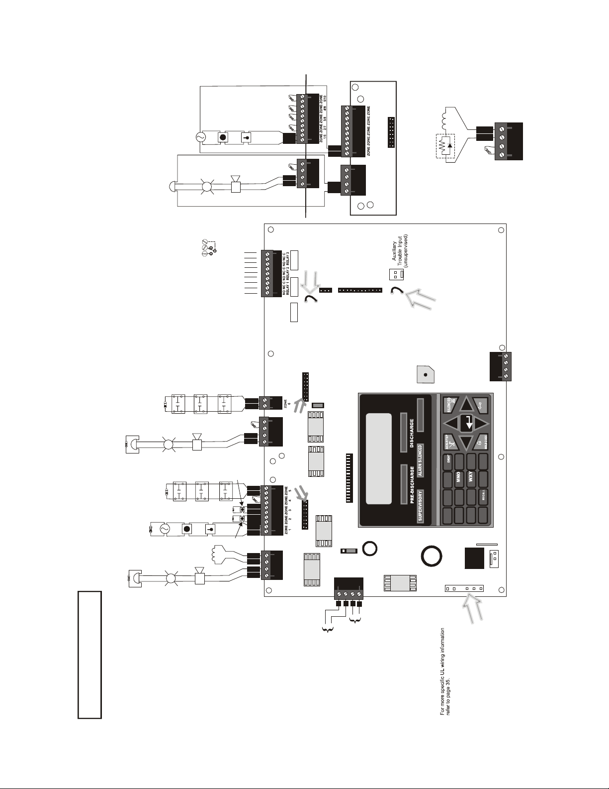
Main Circuit Board
A
Style D (Cl ass A) IDC
-
A
+
11
-
A
TB4/
TB6
A
+
11
TB1
J2
-
B
22
B
CAC5
REL-4.7K
Releasing Circuit
+
OUT1 OUT2
+ - + -
Class A Converter Module
Ω
Dummy load all unused circuits with
4.7K , ½ watt End-of-Line resistors
+
Style Z (Class A) N A C
NO NC C
+
+
Supervisory*
NO NC CNO NC C NO NC C
-
A
11 2
A
+
-
A
OUT1/3 OUT2/4
11
A
+
TB5/
TB7
OUT OUT
TB2
Cut this jumper to
enable Supervisory
relay when 4XTMF
module is installed
(Supervised, Power-limited, Class 2)
Unused
Output Circuit
TB5
Ω
P/N 71245
4.7K dummy load
J6
J5
J4
4XTMF OPT BD
JP30
JP24
(See Style D illustrated near right edge of board).
Ω
4.7K , ½ watt End-of-Line Resistor PN 71252
Alarm* Troub le*
A Fail Safe Trouble
relay switches to the
NC position during
trouble conditions and
Nonsupervised relay contacts
Contact Ratings:
2.0 amps @ 30 VDC (resistive)
0.5 amps @ 30 VAC (resistive)
Contacts shown below in normal
condition (AC power with no alarm,
3 Programmable Relays
trouble or supervisory activity).
under loss of all power.
(* )Factory default relay programming
TB8
Input Initiating Device Circuit - TB4 & TB6
IDCs 1 through 6, Style B (Class B) (Supervised, Power Limited, Class 2)
J7
or
Open
Devices
Normally
Pressure
Switches
Waterflow
Input IDC
Circuit #6
Waterflow
+
NAC
Output
Circuit #3
Special Application Power
Ω
Output Circuits - TB5 & TB7
4.7K , ½ watt End-of-Line Resistor PN 71252
3.0 amps max. per circuit. (See Style Z illustrated near right edge of board).
AC Output Circuit #2 (Releasing), Style Y (Class B) (Supervised, Nonpower Limited, Class 1)
N
+
In this example, NAC Output Circuit s#1, #3 & #4, Styl e Y (Class B) (Supervised, Power Limited, Class 2)
NAC
Output
Circuit #1
polarized
+
+
or
Open
Tampe r
Normally
Pressure
Switches
Input IDC
Circuit #5
Supervisory
Input IDC
Circuit #1
bell
pull
station
smoke
detector
Output
Circuit #2
+
+
horn
strobe
polarized
polarized
manual
heat
detector
abort
Releasing
TB6
B
-
+ -
B
+
66
Output
Circui t #3
B
-
+ - + -
B
+
33
OUT3 OUT4
TB7
release
5
B
-
5
B
+
B
-
B
+
33
-
B
22
B
+
-
B
+ - + - + - + - + -
11
B
+
switch
B
-
22
B
+
-
B
11
B
+
+ - + -
CAC5 Class A Converter Module
TB4
OUT1 OUT2
TB5
JP43
Remove jumper JP43
to disable Ground Fault
Detection circuit (only
with approval of AHJ).
FIRE ALARM
ABORT
AC POWER
J3
J2
321
JP31
RST AUX
PWR
RST/NONRST
AUXPWR
TB9
-
-
+
+
2
4
1
3
Cut this jumper to supervise
the 4XTMF module when
installed (see J4 & J5)
ALARM
TROUBLE
ST
1
DEF
3
ABC
2
1
ENTER
ESC
CLEAR
6
JKL
89
5
GHI
PRS TU V
7
4
ANN-BUS
A B
- +
- +
GND PWR
TB3
RESET
DRILL
MODE
_/.
#
0
QZ_
*
- +
J12
BATTERY
Battery
nonpower-limited
24 VDC, supervised,
J15
26 Amp Hour maximum
Removing Ground Fault
Power Supply Connector J15
Basic System Connections
DisableJumper JP43 voids UL/NFPA
Style/Class identifications for circuits.
Remove jumper JP43 only with the
approval of the AHJ
Important!
(Authority Having Jurisdiction).
Special Application
DC Power Outputs (24 VDC)
Nonsupervised, power-limited (Class 2) circuits
Supervise with a power supervision relay EOLR-1
Resettable Power - 24 VDC filtered,
power-limited, Class 2 (0.500 amps
maximum) to smoke detectors (IDC).
Supervise with a power supervision
relay E OLR-1.
Nonresettable or Resettable Power
Jumper selectable by JP31, 24 VDC filtered,
power-limited, Class 2 (0.500 amps maximum)
Supervise with a power
supervision relay EOLR-1.. NonresettablePower
suitable for powering annunciators, Resettable
Power suitable for powering smoke detectors.
Configure TB9, Terminals 1 & 2
as Resettable or Nonresettable Power.
• Resettable Power - jumper JP31
pins 2 & 3.
• Nonresettable Power - jumper JP31 pins 1 & 2
(as shown).
10 MRP-2002 & MRP-2002E PN 53049:A 4/16/2007
Page 11

Product Features Product Description
SECTION 1 Product Description
The MRP-2002 is a six zone FACP for single and dual hazard agent releasing applications. The
FACP provides reliable fire detection, signaling and protection for commercial, industrial and
institutional buildings requiring agent-based releasing. The FACP is compatible with System
Sensor’s i
trouble signal to the FACP indicating the need for cleaning and a supervisory ‘freeze’ signal when
the ambient temperature falls below the detector rating of approximately 45
Sensor for i
compatible with conventional input devices such as two-wire smoke detectors, four-wire smoke
detectors, pull stations, waterflow devices, tamper switches and other normally-open contact
devices. Refer to Device Compatibility Document for a complete listing of compatible devices.
Four outputs are programmable as NACs (Notification Appliance Circuits) or releasing solenoids.
Three programmable Form-C relays (factory programmed for Alarm, Trouble and Supervisory)
and 24 VDC special application resettable and nonresettable power outputs are also included on the
main circuit board. The FACP supervises all wiring, AC voltage, battery charger and battery level.
Activation of a compatible smoke detector or any normally-open fire alarm initiating device will
activate audible and visual signaling devices, illuminate an indicator, display alarm information on
the panel’s LCD, sound the piezo sounder at the FACP, activate the FACP alarm relay and operate
an optional module used to notify a remote station or initiate an auxiliary control functio n.
3
detectors which are conventional smoke detectors that can transmit a maintenance
o
3
Installation and Maintenance Instructions). In addition, the control panel is
F (refer to System
The MRP-2002E offers the same features as the MRP-2002 but allows connection to 220/240 VAC.
Unless otherwise specified, the information in this manual applies to both the 110/120 VAC and
220/240 VAC versions of the panels.
1.1 Product Features
• Six programmable Style B (Class B) IDCs (Initiating Device Circuit)
• Four programmable Style Y (Class B) output circuits - (special application power)
• Three programmable Form-C relays
• 7.0 amps total 24 VDC output current
• Resettable and non-resettable output power
• Built-in Programmer
• ANN-BUS for connection to optional:
ANN-80 Remote LCD Annunciator
ANN-I/O LED Driver
ANN-S/PG Printer Module
ANN-RLY Relay Module
ANN-LED Annunciator Module
• 80-character LCD display (backlit)
• Real-time clock/calendar with daylight savings time control
• History log with 256 event storage
MRP-2002 & MRP-2002E PN 53049:A 4/16/2007 11
Page 12

Product Description Product Features
• Control Buttons
ACK (Acknowledge)
Alarm Silence
System Reset/Lamp Test
Drill
• Indicators
Fire Alarm
Supervisory
Trouble
AC Power
Alarm Silence
Discharge
Pre-Discharge
Abort
• Piezo sounder for alarm, trouble and supervisory
• 24 volt operation
• Low AC voltage sense
• Outputs Programmable for:
Releasing Solenoids
NACs programmable for:
Silence Inhibit
Auto-Silence
Strobe Synchronization (System Sensor, Wheelock, Gentex, Faraday, Amseco)
Selective Silence (horn-strobe mute)
Temporal or Steady Signal
Silenceable or Nonsilenceable
Release Stage Sounder
• Designed for agent releasing standards NFPA 12, 12A and 12B
• Disable/Enable control per input zone and output zone
• Extensive transient protection
• Dual hazard operation
• Adjustable pre-discharge, discharge and waterflow delay timers
• Cross-zone (double-interlock) capability
• Pre-programmed and custom application templates
• Programmable Abort operation
• Automatic battery charger with charger supervision
• Silent or audible walktest capabilities
• Optional Dress Panel DP-51050 (red)
• Optional Trim Ring TR-CE (red) for semi-flush mounting the cabinet
• Optional CAC-5X Class A Converter Module for Outputs and IDCs
• Optional 4XTMF Municipal Box Transmitter Module
• Optional Digital Alarm Communicators (411, 411UD, 411UDAC)
12 MRP-2002 & MRP-2002E PN 53049:A 4/16/2007
Page 13

Specifications Product Description
1.2 Specifications
AC Power
MRP-2002: 120 VAC, 60 Hz, 3.66 amps
MRP-2002E: 240 VAC, 50 Hz, 2.085 amps
Wire size: minimum #14 AWG (2.0 mm
Supervised, nonpower-limited
Battery (sealed lead acid only) - J12
Maximum Charging Circuit - Normal Flat Charge: 27.6 VDC @ 1.4 amp
Supervised, nonpower-limited
Maximum Charger Capacity: 26 Amp Hour battery (two 18 Amp Hour batteries can be housed
in the F A CP cabinet. Larger batteries require separate battery box such as the BB-26 or BB-55)
Minimum Battery Size: 7 Amp Hour
Initiating Device Circuits - TB4 and TB6
Alarm Zones 1 - 5 on TB 4
Alarm Zone 6 on TB6
Supervised and power-limited circuitry
Operation: All zones Style B (Class B)
Normal Operating Voltage: Nominal 20 VDC
Alarm Current: 15 mA minimum
Short Circuit Current: 40 mA max.
Maximum Loop Resistance: 100 ohms
End-of-Line Resistor: 4.7KΩ, 1/2 watt (Part #71252)
Standby Current: 2 mA
Refer to the Device Compatibility Document for listed compatible devices
Notification Appliance and Releasing Circuit(s) - TB5 and TB7
Four Output Circuits
Operation: Style Y (Class B)
Special Application power
Supervised and power-limited circuitry
Normal Operating Voltage: Nominal 24 VDC
Maximum Signaling Current: 7.0 amps (3.0 amps maximum per NAC)
End-of-Line Resistor: 4.7KΩ, 1/2 watt (Part #71252)
Max. Wiring Voltage Drop: 1.5 VDC
Refer to the Device Compatibility Document for compatible listed devices
2
) with 600V insulation
1
Form-C Relays - Programmable - TB8
Relay 1 (factory default programmed as Alarm Relay)
Relay 2 (factory default programmed as fail-safe Trouble Relay)
Relay 3 (factory default programmed as Supervisory Relay)
Relay Contact Ratings: 2 amps @ 30 VDC (resistive) and 0.5 amps @ 30 VAC (resistive)
Auxiliary Trouble Input - J6
The Auxiliary Trouble Input is an open collector, unsupervised circuit which can be used to
monitor external devices for trouble conditions. It can be connected to the trouble bus of a
peripheral, such as a power supply, which is compatible with open collector circuits.
All connections must be in conduit, less than 20 ft. (610 cm) in length in the same room.
Special Application Resettable Power - TB9
Operating Voltage: Nominal 24 VDC
Maximum Available Current: 500 mA - appropriate for powering 4-wire smoke detectors (see
note 1)
Power-limited Circuitry
Refer to the Device Compatibility Document for compatible listed devices
1. Total current for resettable power, nonresettable power and Output Circuits must not exceed
7.0 amps.
MRP-2002 & MRP-2002E PN 53049:A 4/16/2007 13
Page 14

Product Description Controls and Indicators
Special Application Resettable or Nonresettable Power - TB9
Operating Voltage: Nominal 24 VDC
Maximum Available Current: 500 mA (see note 1 on previous page)
Power-limited Circuitry
Jumper selectable by JP31 for resettable or nonresettable power:
Jumper pins 1 & 2 on JP31 for nonresettable power
Jumper pins 2 & 3 on JP31 for resettable power
Refer to the Device Compatibility Document for compatible listed devices
1.3 Controls and Indicators
LCD Display
The FACP uses an 80-character
(4 lines X 20 characters) high viewing angle
LCD display. The display includes a long life
LED backlight that remains illuminated. If AC
power is lost and the system is not in alarm, the
LED backlight will turn off to conserve batteries.
Key Panel
Mounted on the main circuit board, the key panel includes a window for the LCD display and
indicators as listed above. The key panel, which is visible with the cabinet door closed, has 25
keys, including a 16 key alpha-numeric pad similar to a telephone keypad.
SYSTEM ALL NORMAL
10:00A 012106
Function keys:
• Acknowledge/Step
• Alarm Silence
• Drill
• System Reset (lamp test)
Service/program keys:
• Keys labeled 1 to 9
• * key
• # key
• 0 (recall) key
• 1st Event key
• Clear key
• Escape key
• Mode key
• Four cursor keys (up, down, left and right)
• Enter key
RP2001kypd.cdr
Figure 1.1 Membrane/Display Panel
14 MRP-2002 & MRP-2002E PN 53049:A 4/16/2007
Page 15

Components Product Description
Local Piezo Sounder
A piezo sounder provides separate and distinct pulse rates for alarm, trouble and supervisory
conditions.
Indicators
Indicators are provided to annunciate the following conditions:
• Fire Alarm - red indicator
• Supervisory - yellow indicator
• AC Power - green indicator
• System Trouble - yellow indicator
• Alarm Silence - yellow indicator
• Discharge - red indicator
• Pre-discharge - red indicator
• Abort - yellow indicator
Local Piezo Sounder
A piezo sounder provides separate and distinct sounds for alarm, trouble, maintenance and
supervisory conditions as follows:
• Alarm - on steady
• Trouble - pulse 1 second on and 1 second off
• Maintenance - pulse ½ second on and ½ second off
• Supervisory - pulse ½ second on and ½ second off
1.4 Components
Main Circuit Board
The main circuit board contains the system’s CPU and other primary components and wiring
interface connectors. Optional modules plug in and are mounted to the main circuit board.
Power Supply
One FLPS-7 power supply is provided standard with each F ACP, mounted to a chassis.
Cabinet
The backbox measures 16.65” (42.29 cm) x 19.0” (48.26 cm) x 5.207” (13.23 cm) and provides
space for two batteries (up to 18 Amp Hours). Also available is optional dress panel (DP-51050
[red] and supplied standard with Canadian FACPs, DP-51050LED for mounting ANN-LED
annunciator modules) which mounts inside the cabinet and trim-ring (TR-CE [red]).
Batteries
The cabinet provides space for two 18 Amp Hour batteries (larger batteries require use of a UL
listed battery box such as the BB-26 or BB-55). Batteries must be ordered separately.
MRP-2002 & MRP-2002E PN 53049:A 4/16/2007 15
Page 16

Product Description Optional Modules and Accessories
1.5 Optional Modules and Accessories
CAC-5X Class A Converter Module
The CAC-5X Module can be used to convert the Style B (Class B) Initiating Device Circuits to
Style D (Class A) and Style Y (Class B) Output Circuits to Style Z (Class A). The modules connect
to J2 and J7 on the FACP main circuit board. Note that two Class A Converter modules are required
to convert all six Output Circuits and four Initiating Device Circuits.
4XTMF Transmitter Module
The 4XTMF provides a supervised output for local energy municipal box transmitter and alarm and
trouble reverse polarity. It includes a disable switch and disable trouble LED. A module jumper
option allows the reverse polarity circuit to open with a system trouble condition if no alarm
condition exists. The 4XTMF mounts to the main circuit board connectors J4 & J5.
ANN-80 LCD Annunciator
The ANN-80 is a remote LCD annunciator that mimics the information displayed on the FACP
LCD display.
ANN-LED Annunciator Module
The ANN-LED Annunciator Module provides three LEDs for each zone: Alarm, Trouble and
Supervisory.
ANN-RLY Relay Module
The ANN-RLY Module, which can be mounted inside the cabinet, provides 10 Form-C relays.
ANN-S/PG Serial/Parallel Printer Gateway
The ANN-S/PG
ANN-I/O LED Driver Module
The ANN-I/O module provides connections to a user supplied graphic annunciator.
DP-51050 Dress Panel
A dress panel DP-51050 (red) is available as an option. The dress panel restricts access to the
system wiring while allowing access to the membrane switch panel.
DP-51050LED Dress Panel
A DP-51050LED dress panel is supplied standard with Canadian versions of the FACP. The dress
panel restricts access to the system wiring while allowing access to the membrane switch panel. It
also allows the installation of an optional ANN-LED annunciator module.
TR-CE Trim-ring
A trim-ring TR-CE (red) is available as an option. The trim-ring allows semi-flush mounting of the
cabinet.
Battery Box
The BB-26 or BB-55 battery box may be used to house two batteries greater than 18 Amp Hour.
The battery box mounts directly below the control panel cabinet, centered to the main circuit board.
module provides a connection for a serial or parallel printer.
16 MRP-2002 & MRP-2002E PN 53049:A 4/16/2007
Page 17
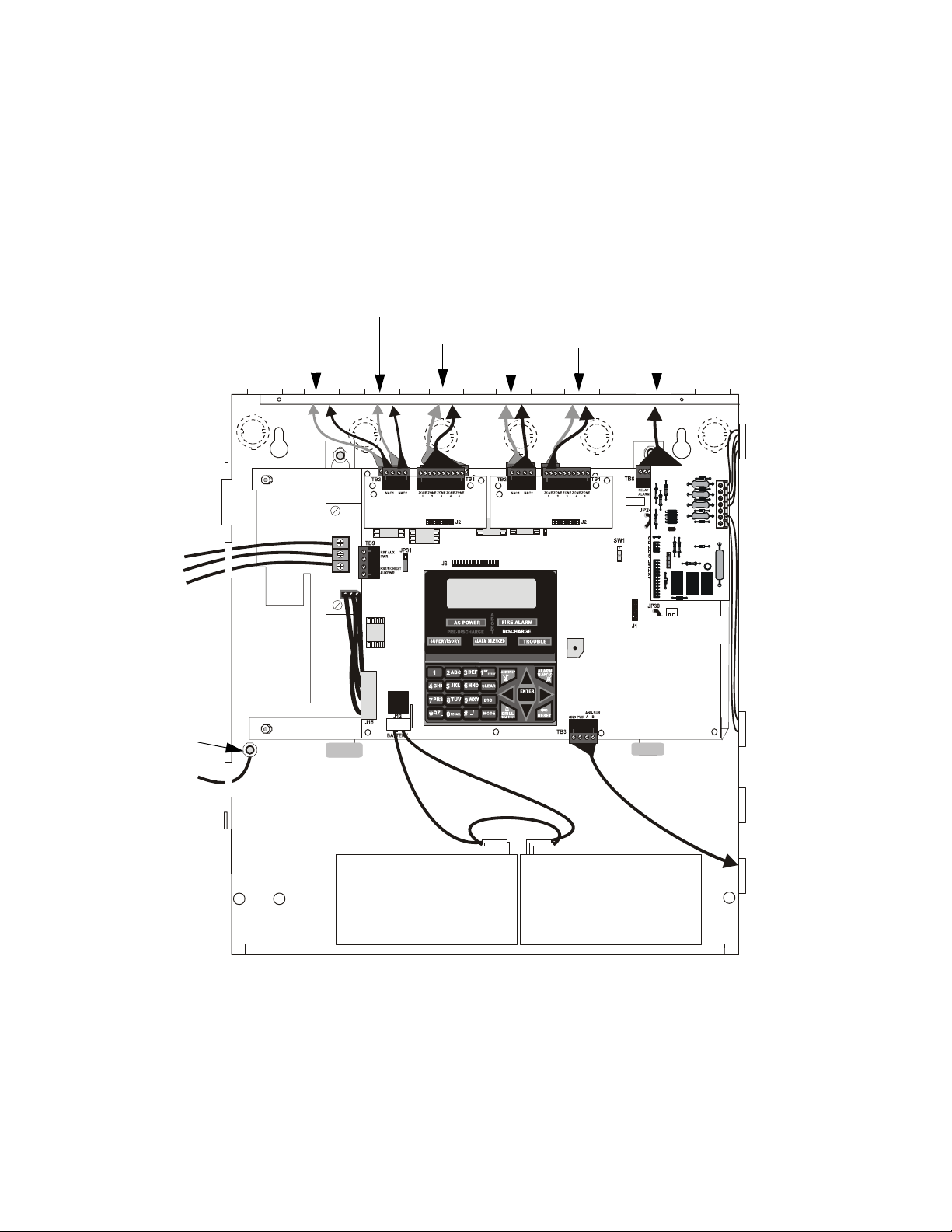
Backbox Mounting Installation
SECTION 2 Installation
The cabinet can be surface mounted or semi-flush mounted. The door is removable during the
installation period by opening and lifting it off the hinges. The cabinet mounts using two key slots
at the top of the backbox and two additional securing holes located at the bottom.
Carefully unpack the system and check for shipping damage. Mount the cabinet in a clean, dry,
vibration-free area where extreme temperatures or levels of humidity are not encountered. The area
should be readily accessible with sufficient room to easily install and maintain the panel. Locate
the top of the cabinet approximately 5 feet (1.5 m) above the floor with the hinge mounting on the
left. Determine the number of conductors required for the devices to be installed. Sufficient
knockouts are provided for wiring convenience. Select the appropriate knockout(s) and pull the
conductors into the box. All wiring should be in accordance with the National and/or Local codes
for fire alarm systems.
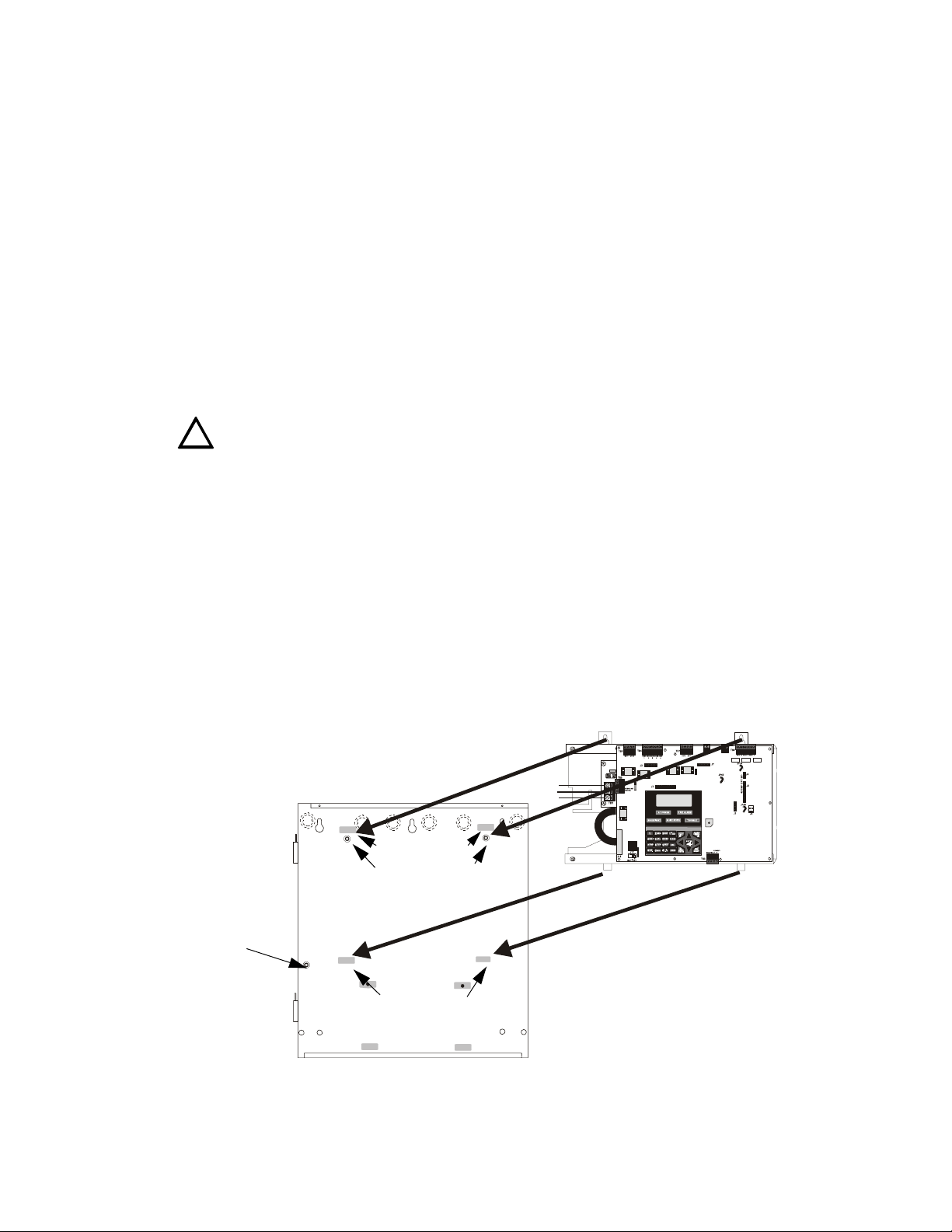
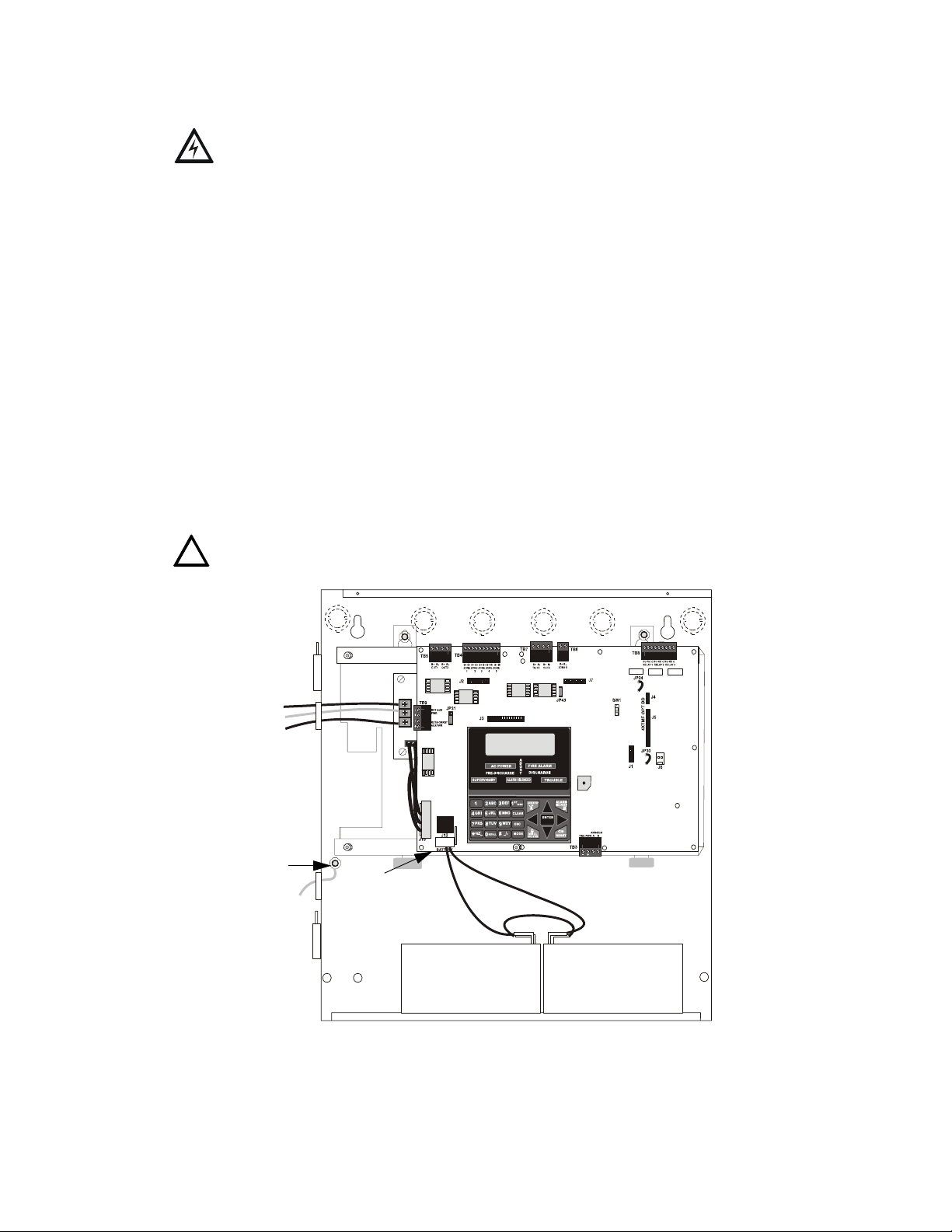
2.1 Backbox Mounting
The circuit board contains static-sensitive components. Always ground yourself with a pr oper wrist
strap before handling any boards so that static charges are removed from the body. Use static
!
suppressive packaging to protect electronic assemblies.
To prevent damage to th e circui t board and to facilitate backbox mounting, the chassis with main
circuit board and transformer can be easily removed. Loosen the two 3/8” nuts securing the top
flanges of the chassis, then slide the chassis up to free it from the lower tabs. Place the chassis
assembly in a protective antistatic bag in a safe location until it can be reinstalled in the backbox.
See Page
grounding stud:
attach solid earth
ground wire (refer to
Figure 2.4 on page 20)
Mark and predrill hole in the wall for the center top keyhole mounting bolt us ing the
dimensions illustrated in Figure 2.2 on page 18
Install center top fastener in the wall with the screw head protruding
Place backbox over the top screw, level and secure
Mark and drill the left and right upper and lower mounting holes
Note: outer holes (closest to sidewall) are used for 16” on-center stud mounting
Install remaining fasteners and tighten
Main CircuitBoard on Chassis
mounting holes
mounting slots
mounting studs
mounting slots
mounting tabs
Backbox
5UDBRDINBOX.CDR
Figure 2.1 Chassis Mounting in Backbox
MRP-2002 & MRP-2002E PN 53049:A 4/16/2007 17
Page 18
Installation Backbox Mounting
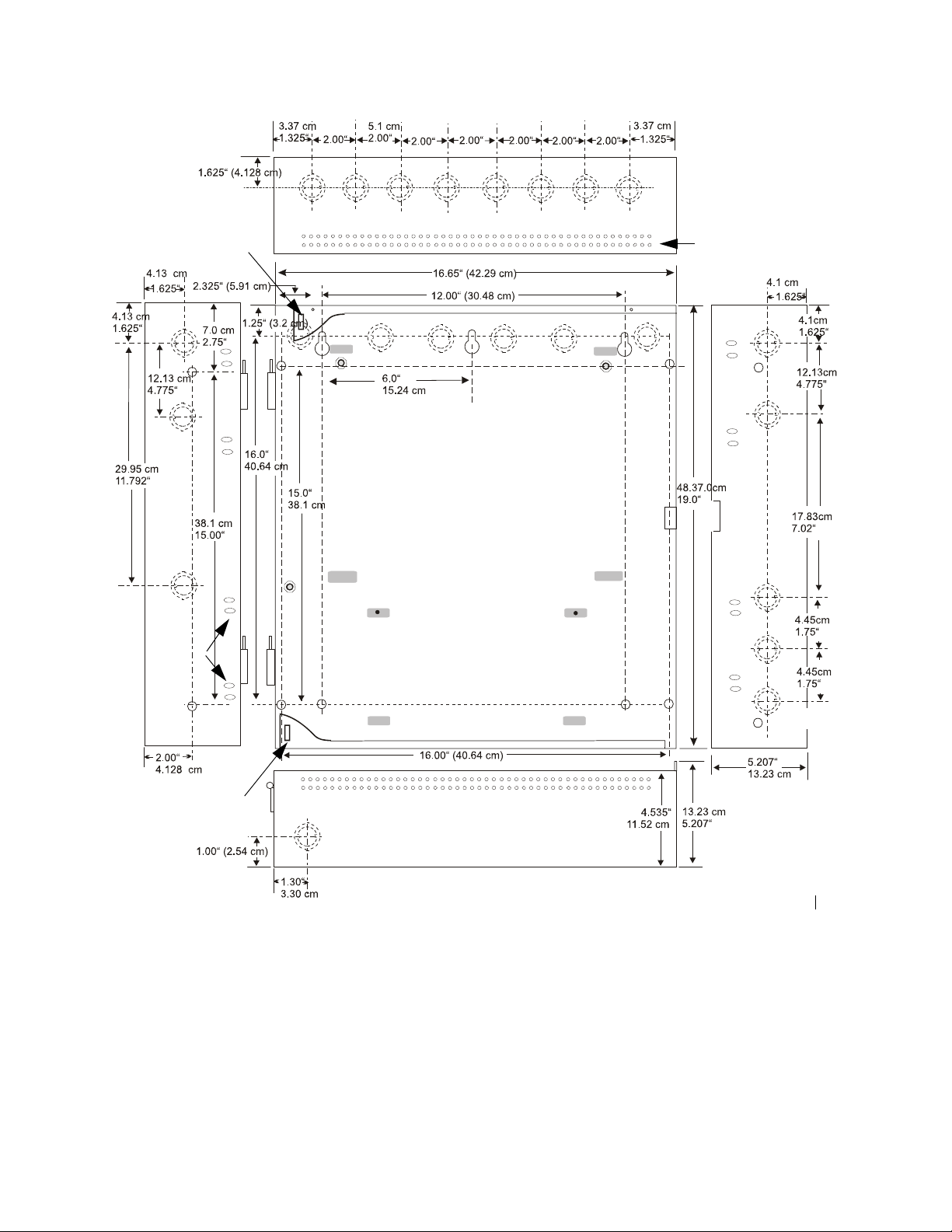
Semi-Flush Mounting
Do not recess box more
than 3.875” into wall to
Hinge Slot for
optional Dress Panel
avoid covering venting
holes on top of box.
Mounting
slots for
optional
Trim Ring
Semi-Flush
mounting hole
Hinge Slot for optional
Dress Panel
9050UDencl.cdr
Figure 2.2 Cabinet Dimensions
18 MRP-2002 & MRP-2002E PN 53049:A 4/16/2007
Page 19
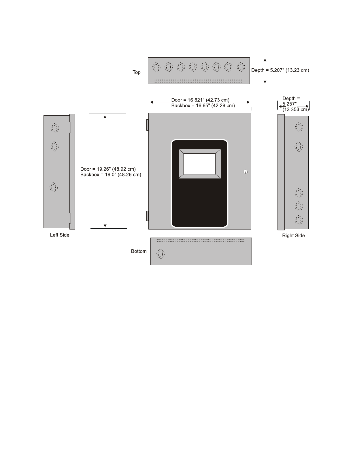
Backbox Mounting Installation
Figure 2.3 Backbox
9050udcab.cdr
MRP-2002 & MRP-2002E PN 53049:A 4/16/2007 19
Page 20
Installation Operating Power
2.2 Operating Power
WARNING: Several different sources of power can be connected to this panel. Disconnect all
sources of power before servicing. The panel and associated equ ipm ent may be damaged by
removing and/or inserting cards, modules or interconnecting cables while this unit is energized.
Primary Power Source (AC) and Earth Ground Connections
AC power connections are made inside the control panel cabinet. The pri mary power source for the
panel is 120 VAC, 60 Hz, 3.66 amps for the MRP-2002 or 240 VAC, 50 HZ, 2.085 amps for the
MRP-2002E. Run a pair of wires (with ground conductor) from the protected premises main
breaker box to the AC terminal block TB1 on the main power supply. As per the National
Electrical Code, use 14 AWG (2.00 mm
insulation. No other equipment may be connected to this circuit. In addition, this circuit must be
provided with overcurrent protection and may not contain any power disconnect devices. A
separate Earth Ground connection must be made to ensure proper panel operation and lightning and
transient protection. Connect the Earth Ground wire [minimum 14 AWG (2.00 mm
grounding stud in the backbox. Do not use conduit for the Earth Ground connection since this does
not provide reliable protection.
Secondary Power Source (Batteries)
Observe polarity when connecting the battery. Connect the battery cable to J12 on the main circuit
board using the plug-in connector and cable provided. The battery charger is current-limited and
capable of charging sealed lead acid batteries. The charger shuts off when the system is in alarm.
2
, 1.6 mm O.D.) or heavier gauge wire with 600V
2
)] to the
WARNING: Battery contains sulfuric acid which can cause severe burns to the skin and eyes and
can destroy fabrics. If contact is made with sulfuric acid, immediately flush the skin or eyes with
!
water for 15 minutes and seek immediate medical attention.
120 VAC Power
Hot (L1)
Ground
Neutral (L2)
Ground Wire
J12
+-
Batteries
rp2001powr.cdr
Figure 2.4 Operating Power Connections
20 MRP-2002 & MRP-2002E PN 53049:A 4/16/2007
Page 21
Input Circuits Installation
2.3 Input Circuits
The MRP-2002 has six programmable IDCs (Initiating Device Circuits). Each circuit is compatible
with System Sensor ’s i
3
smoke detectors which generate a maintenance signal when the detector
becomes dirty and a separate supervisory ‘freeze’ signal when ambient temperature falls below the
detector rating of approximately 45
o
F. The maximum loop resistance limit for each IDC is 100
ohms. The maximum number of detectors per zone is 25. The field wiring for each zone is
supervised for opens, shorts and ground faults. All conditions are visually and audibly
annunciated.
Each circuit is configured for Style B (Class B) operation and will accept i
normally-open contact devices as well as conventional 2-wire or 4-wire, 24 VDC smoke detectors.
Refer to the Device Compatibility Document for a list of compatible devices.
Initiating Device Circuits can be converted to Style D (Class A) by installing the optional Class A
Converter module. Refer to "CAC-5X Class A Converter Module" on page 26.
Class B Initiating Device Circuits (supervised and power-limited) 4.7 KΩ, ½ watt resistor P/N:71252
(refer to Device Compatibility Document for list of compatible relays)
Resettable 24 VDC
4-wire smoke
detector power
(500 mA maximum)
UL listed Power Supervision Relay
UL listed compatible 4-wire smoke detector
manual pull stations
heat detectors
Dummy load all unused
circuits - 4.7 K
resistor (P/N: 71245)
Ω, ½ watt
abort
switch
manual
release
3
smoke detectors, any
Input IDC
Waterflow Circuit
Normally Open
Waterflow
Devices or
Pressure Switches
Figure 2.5 IDC Connections
MRP-2002 & MRP-2002E PN 53049:A 4/16/2007 21
ms-10UDidc.cdr
Page 22
Installation Input Circuits
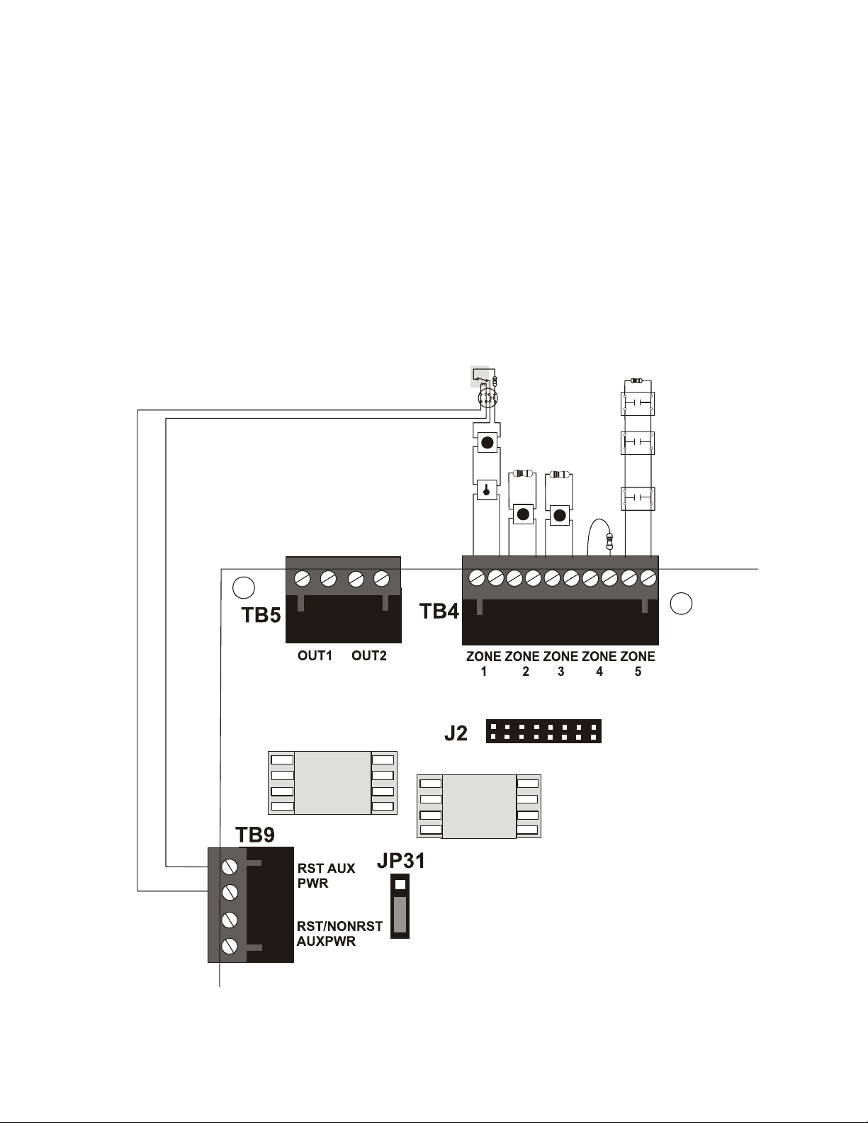
Combination Waterflow/Su pervisory Zone
A combination Waterflow/Supervisory circuit allows an FACP to distinguish between an Alarm
switch (waterflow device) and a Supervisory switch (tamper) installed on the same circuit. Any
circuit can be programmed as a Combo Type zone. The following figure illustrates the wiring of
Zone 2 as a Style B (Class B) Waterflow/Supervisory circuit.
Class B Initiating Device Circuits (supervised and power-limited)
4.7 KΩ, ½ watt resistor P/N:71252
Supervisory Switch
(tamper)
In-Line-Resistor
1.2 KΩ, ½ watt resistor P/N: 75579
Alarm Switch
(waterflow)
Dummy load all unused
circuits - 4.7 KΩ, ½ watt
resistor (P/N: 71245)
Figure 2.6 Style B Combination Circuit on Zone 2
Requirements for the Combination Waterflow/Supervisory circuit are as follows:
The Waterflow Alarm Switch must connect to the FACP Initiating Device Circuit before
the In-Line Resistor as shown in Figure 2.6
The Supervisory Switch must connect to the FACP Initiating Device Circuit after the In-
Line Resistor as shown in Figure 2.6
ms10udcomboIDC.cdr
Program the FACP Initiating Devi ce Circui t as a Combination circuit as described in
"Input Zones" on page 50. Note that since a Waterflow Supervisory Swit ch is inclu ded in
a Combination circuit, the waterflow delay must be taken into consideration. Refer to
"Waterflow Delay" on page 68.
Waterflow Alarm Switch activation causes the panel to latch into alarm until the alarm
condition is cleared and the FACP is reset
Supervisory Switch activation causes the panel to latch the supervisory condition if the
Combo type code is selected or track (the panel will clear when the supervisory condition
is cleared) if the Combo Autoresettable Supervisory type code is selected
22 MRP-2002 & MRP-2002E PN 53049:A 4/16/2007
Page 23
Output Circuits Installation
2.4 Output Circuits
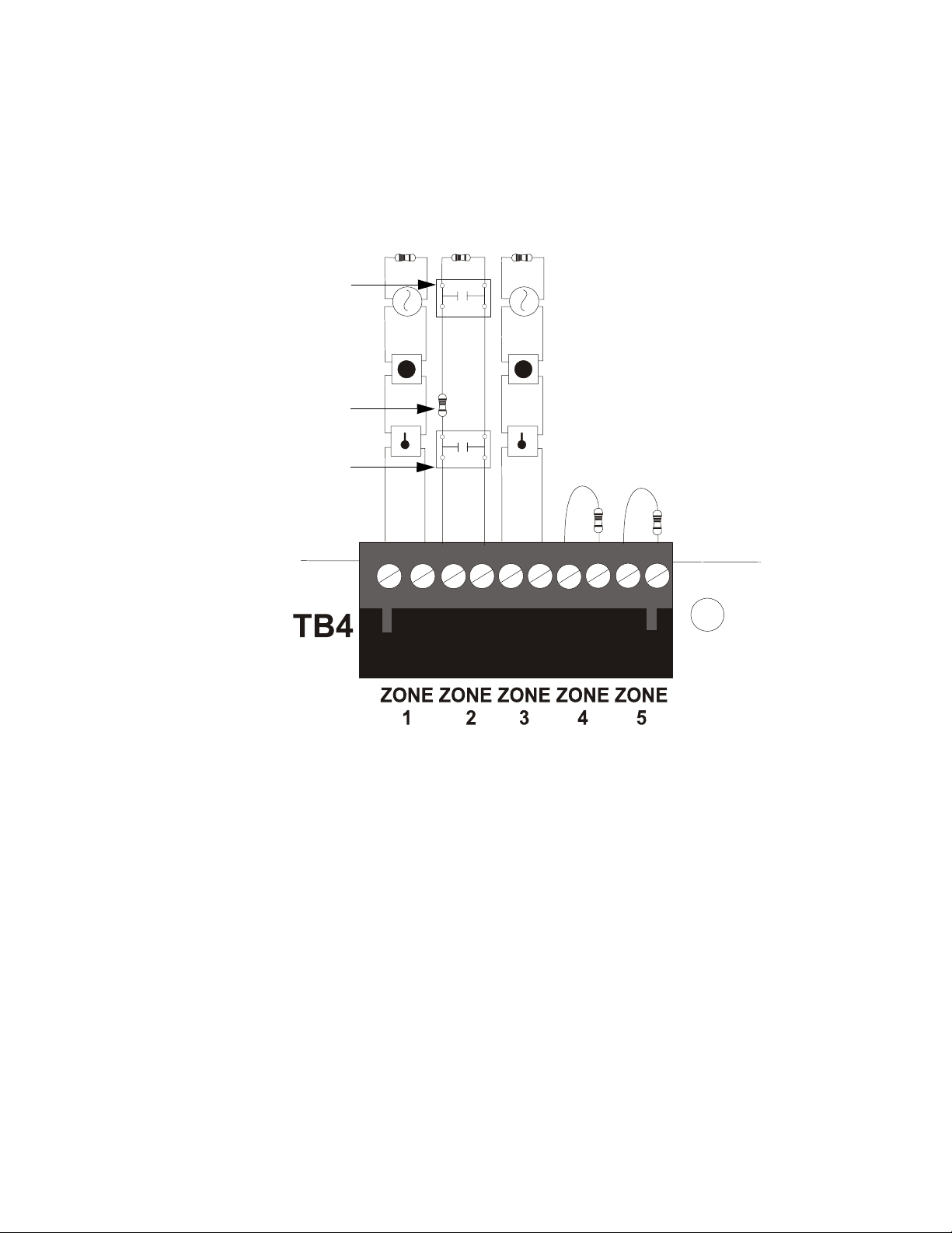
2.4.1 Outputs/Notification Appliance/Releasing Circuits
Each of the four Style Y (Class B) Notification Appliance Circuits can output a maximum of 3.0
amps of current. Total current drawn from these as well as other DC power outputs cannot exceed
7.0 amps (refer to battery calculations section). Each circuit is supervised, power-limited and
provides special application power. Refer to the Device Compatibility Document for a listing of
compatible notification appliances.
The NACs can be converted to Style Z (Class A) by installing two optional Class A Converter
module. Refer to "CAC-5X Class A Converter Module" on page 26.
Class B Notification Appliance Circuits (supervised and power-limited)
4.7 KΩ, ½ watt resistor P/N:71252
Ferrite Beads
P/N 29150
Polarized Bell
Polarized Strobe
Polarized Horn
+ - + -
Polarized Bell
Polarized Strobe
Polarized Horn
Releasing Solenoid
Notification Appliance Circuits
polarity shown in alarm condition
Ferrite Bead
P/N 29150
Note: Short Circuit Supervision must be enabled when using the
REL-4.7K for Canadian Applications. Refer to the section titled
"Release Circuit 1 or Release Circuit 2" on page 58 for information
on enabling short circuit supervision.
Dummy load any unused
circuits (P/N: 71245)
+ - + -
rp2001nac.cdr
Ferrite Bead (P/N 29150)
Large gauge wire
should be looped
through bead at least
once as illustrated.
Smaller gauge wire can
be looped more often.
Ferrite Bead in open position
Ferrite Bead in closed position
Figure 2.7 NAC/Output Connections
MRP-2002 & MRP-2002E PN 53049:A 4/16/2007 23
Page 24
Installation Output Circuits
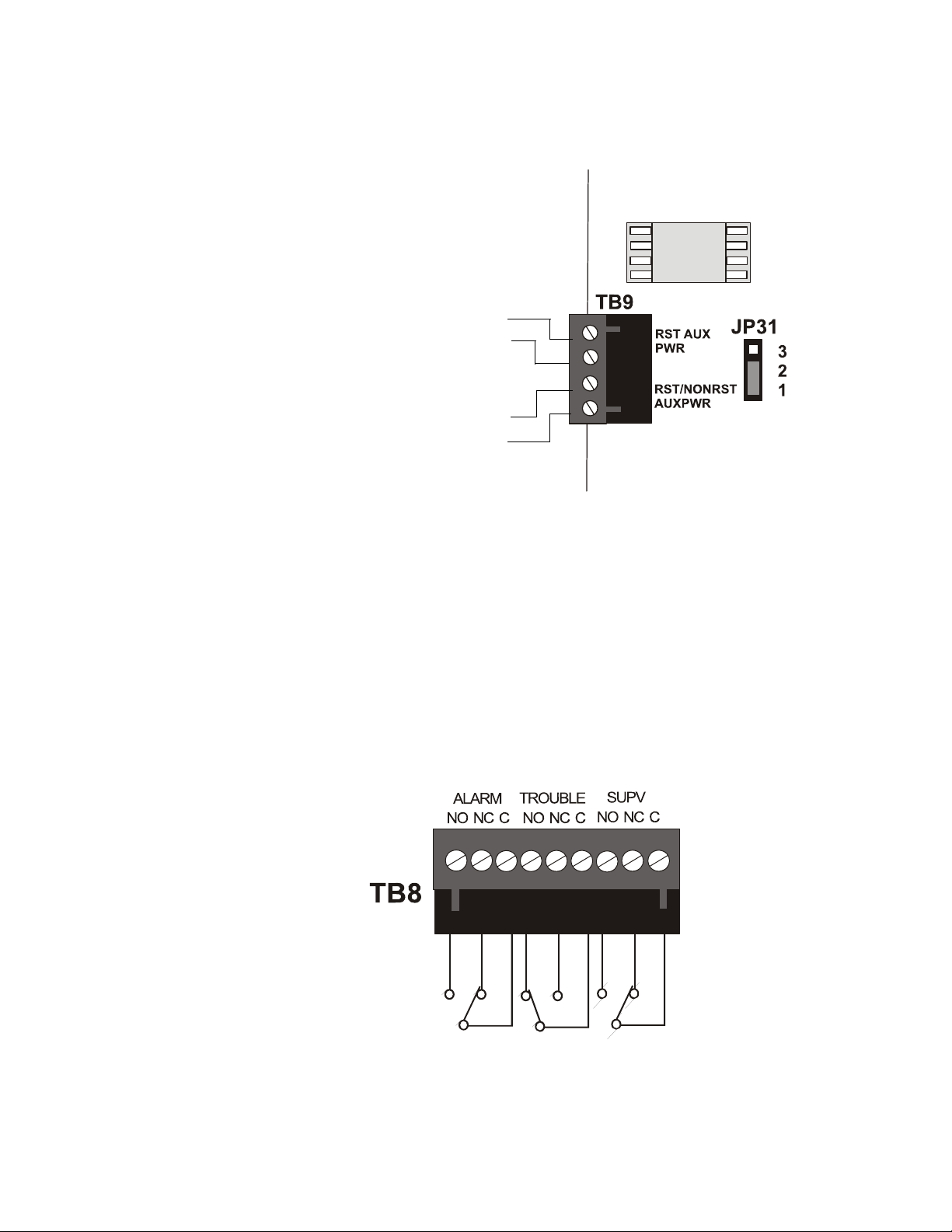
2.4.2 Special Application DC Power Output Connections
Special Application Resettable and Nonresettable 24 VDC power is available on the MRP-2002
control panel.
Special Application
4-Wire Smoke Detector Power (500 mA)
24 VDC filtered, resettable power for 4-wire smoke detectors
can be obtained from these terminals (power-limited)
Special Application
Resettable or Nonresettable Power (500 mA)
24 VDC filtered, resettable or nonresettable power can be
obtained from these terminals (power-limited)
• Jumper JP31 pins 1 & 2 for nonresettable power (as
illustrated in figure to right)
-
4
+
3
-
2
+
1
ms-10UDtb9.cdr
• Jumper JP31 pins 2 & 3 for resettable power
Figure 2.8 Special Application Auxiliary Power
2.4.3 Relays - Programmable
The MRP-2002 control panel provides a factory default programmed alarm relay, fail-safe trouble
relay and supervisory relay. Each relay can be programmed to activate for other conditions (refer
to "On-Board Relays" on page 64). Each Form-C relay is rated for 2 amps @ 30VDC (resistive)
and 0.5 amps @ 30 VAC (resistive).
Note that relay connections must be power-limited.
Note: Relay contacts are shown with
power applied to the panel and no active
troubles, alarms or supervisories.
The Trouble Relay is a fail-safe relay
which will transfer on any trouble or
total power failure.
ms10udrelay.cdr
Figure 2.9 Relay Terminals
24 MRP-2002 & MRP-2002E PN 53049:A 4/16/2007
Page 25
Power-limited Wiring Requirements Installation
2.5 Power-limited Wiring Requirements
Power-limited and nonpower-limited circuit wiring must remain separated in the cabinet. All
power-limited circuit wiring must remain at least 0.25” (6.35 mm) away from any nonpowerlimited circuit wiring. Furthermore, all power-limited and nonpower-limited circuit wiring must
enter and exit the cabinet through different knockouts and/or conduits. A typical wiring diagram is
illustrated below.
*Note: In certain applications, an NAC (power-limited circuit) could be adjacent
to a releasing circuit (nonpower-limited without supervision kit REL-4.7K)
Nonpower-limited Circuits*
Power-limited Circuits (Class 2)
AC Power
120 VAC
Hot (L1)
Ground
Neutral (L2)
earth
ground
CAC-5X
Power-limited Circuits (Class 2)
Power-limited
Circuits
(Class 2)
CAC-5X
4XTMF
Nonpowerlimited
Circuit
Nonpowerlimited
Circuit
Power-limited
Circuit (Class 2)
Agent Releasing FACP
Figure 2.10 Typical UL Power-limited Wiring Requirements
MRP-2002 & MRP-2002E PN 53049:A 4/16/2007 25
RP2001ULwire.cdr
Page 26
Installation Inst allation of Optional Modules
2.6 Installation of Optional Modules
CAUTION: Remove all power (AC and DC) before installing or removing modules or wiring.
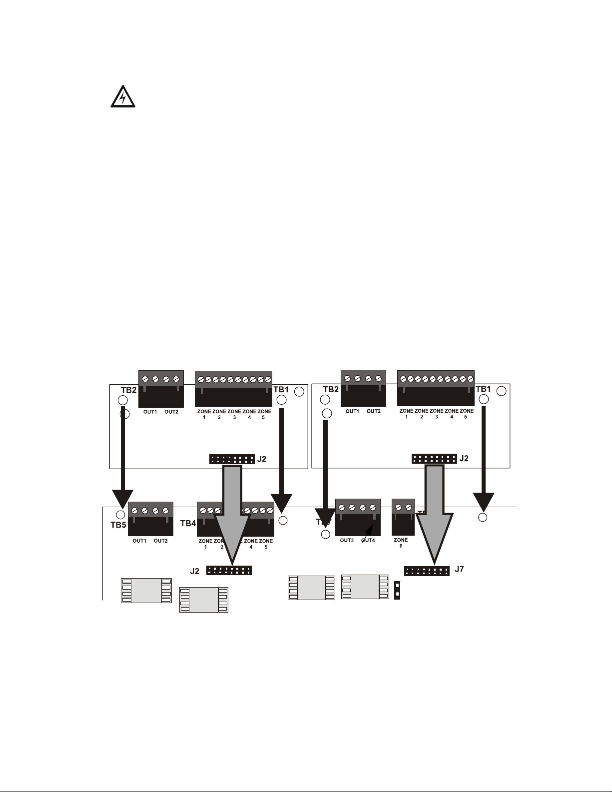
2.6.1 CAC-5X Class A Converter Module
2.6.1.1 Installation
The CAC-5X Module can be used to convert five Style B (Class B) Initiating Device Circuits to
Style D (Class A) and the two Style Y (Class B) Notification Appliance Circuits to Style Z
(Class A). Two CAC-5X Modules are required to convert all Output Circuits and/or Initiating
Device Circuits to Class A. The modules plug into connector J2 which is located at the top left
of the main circuit board and J7 which is located at the top center of the main circuit board.
To install the CAC-5X, remove the two main circuit board mounting screws referenced in the
following illustration and replace with the two supplied male/female standoffs in the locations
indicated in the following figure. Carefully align the connector on the CAC-5X with J2 on the
FACP main circuit board and press the module securely into place. Make certain the pins are
properly aligned to prevent bending or breaking of any connector pins. Secure the CAC-5X to
the standoffs with the screws that were just removed.
T o install the second CAC-5X on J7, remove the main circuit board mounting screw referenced
in the following illustration and replace with the supplied male/female standoff. Insert the
supplied plastic standoff in the location indicated in the following illustration. Carefully align
the connector on the CAC-5X with J7 and press the module securely into place. Make certain
the pins are properly aligned to prevent bending or breaking of any connector pins. Secure the
CAC-5X to the metal standoff with the screw that was just removed.
Installation on J2 Connector
CAC-5X Module
Metal
Standoff
Installation on J7 Connector
CAC-5X Module
Metal
Standoff
Main Circuit Board
Figure 2.11 CAC-5X Module Installation
Plastic
Standoff
Metal
Standoff
rp2001cac5mnt.cdr
26 MRP-2002 & MRP-2002E PN 53049:A 4/16/2007
Page 27
Installation of Optional Modules Installation
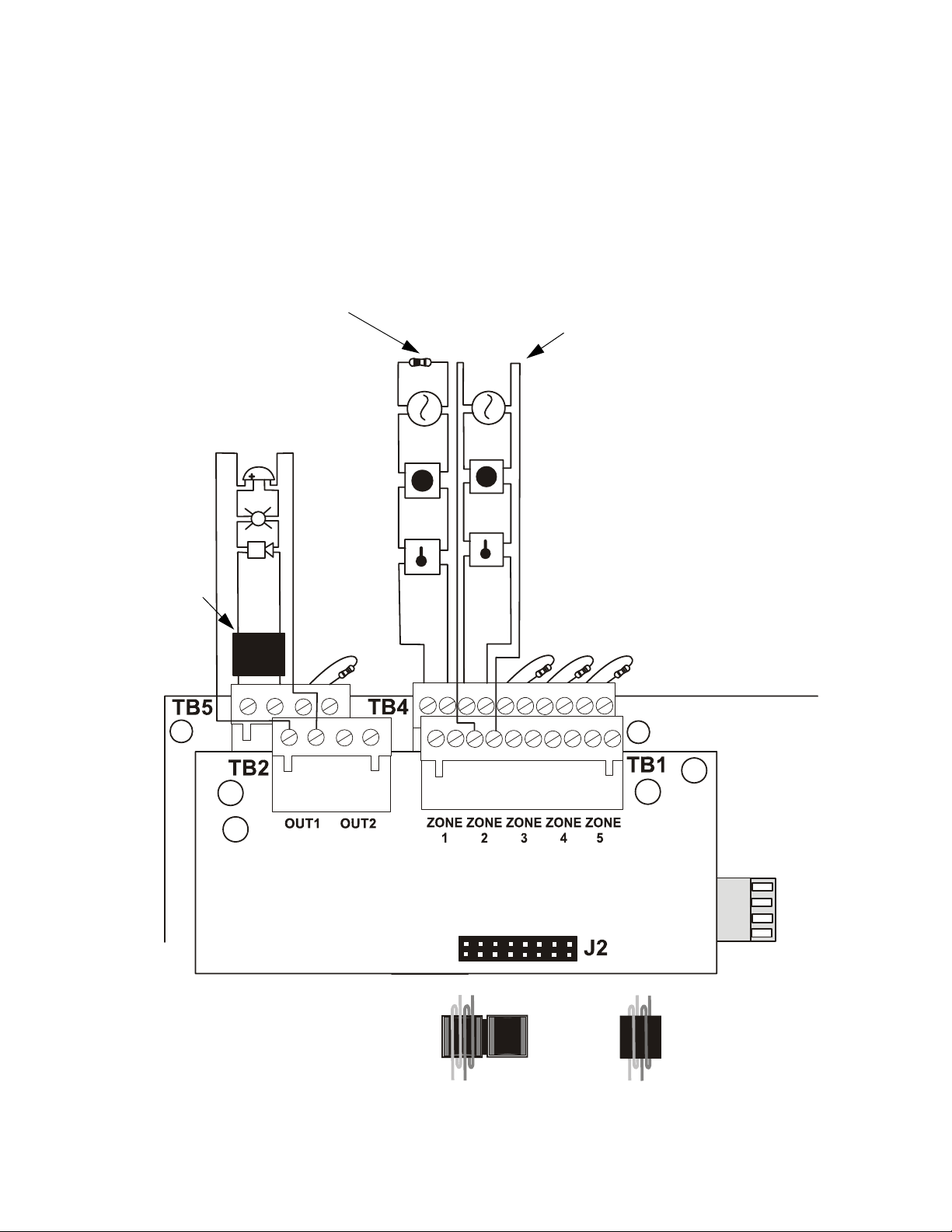
2.6.1.2 Wiring NACs and IDCs for Class A
Wire the Style Z (Class A) Notification Appliance Circuits using TB5 of the FACP main circuit
board and TB2 of the CAC-5X module. Wire the Style D (Class A) Initiating Device Circuits
using TB4 of the FACP main circuit board and TB1 of the CAC-5X. Note that the wiring will
be identical when using TB7 NAC and TB6 IDC of the FACP. Make certain to observe polarity
when connecting the devices to the circuits. The B+ and A+ terminals must comprise the feed
and return for the positive side of a device and the B- and A- terminals must comprise the feed
and return for the negative side of a device. To configure any of the zones for Class B when the
CAC-5X is installed, simply wire to the B+ and B- input on the FACP terminal(s) and install the
End-of-Line Resistor after the last device on the circuit. Do not wire to the corresponding A+
and A- terminals on the CAC-5X module.
Class B (Style B) IDC - 4.7 KΩ
½ watt ELR resistor
P/N:71252 (supervised and power-limited)
Class A (Style Z) NAC
(supervised and power-limited)
Polarized
Bell
Polarized
Strobe
Polarized
Horn
Ferrite Bead
P/N 29150
Circuit polarities
shown in alarm
condition
B+ B- B+ B-
A+ A-
A+ A-
Smoke
Pull Station
Heat
B+ B- B+ B- B+ B- B+ B- B+ B-
Smoke
Pull Station
Heat
A+ A- A+ A- A+ A- A+ A- A+ A-
Class A (Style D) IDC
(supervised and power-limited)
Dummy load all unused
circuits - 4.7 K
½ watt resistor
(P/N: 71245)
FACP Main
Circuit Board
Ω
CAC-5X Class A Converter Module
Large gauge wire should be looped through
bead at least once as illustrated. Smaller
gauge wire can be looped more often.
Ferrite Bead in open position
2550ferr.cdr
Ferrite Bead in closed position
ms10udclassa.cdr
Figure 2.12 Wiring NACs and IDCs for Class A Operation
MRP-2002 & MRP-2002E PN 53049:A 4/16/2007 27
Page 28
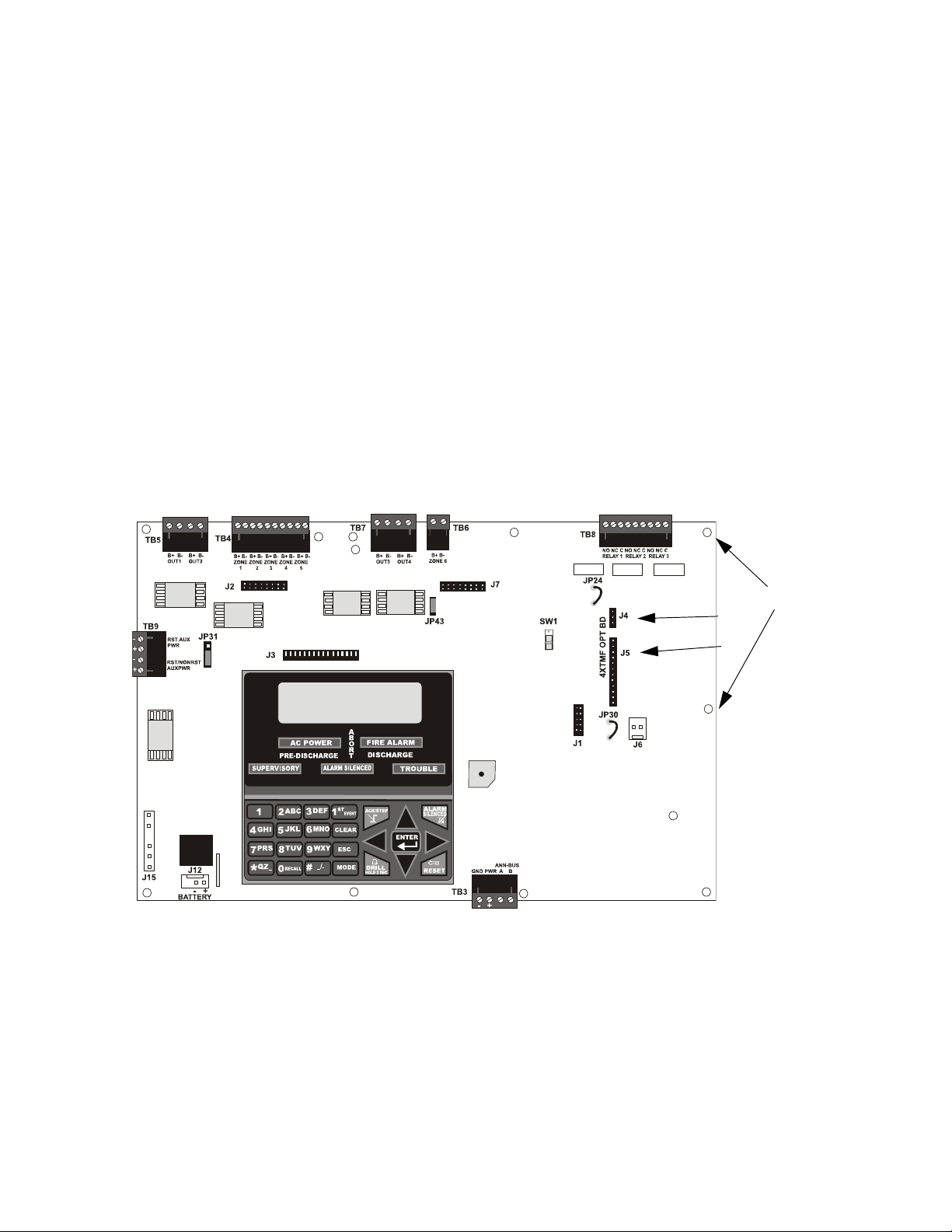
Installation Inst allation of Optional Modules
2.6.2 4XTMF Municipal Box Transmitter Option Module
The 4XTMF module can be plugged into connectors J4 and J5 on the main circuit board.
The following steps must be followed when installing the 4XTMF module:
1. Remove all power (AC and DC) from the FACP before installing the modules
2. Cut jumper JP30 on the main circuit board to allow the control panel to supervise the
placement of the 4XTMF option module
3. Install the two supplied metal standoffs in the locations indicated. These standoffs provide
the required earth ground protection
4. Carefully plug the connectors on the option module into connectors J4 and J5 on the FACP
main circuit board, being careful not to bend any pins
5. Secure the option module to the standoff on the main circuit board with the supplied screws
6. When the installation has been completed, connect the wiring to the modules as indicated in
the following sections
7. Test system for proper operation
Figure 2.13 4XTMF Option Module Connection
Standoffs
J4
J5
rp2001bord.cdr
28 MRP-2002 & MRP-2002E PN 53049:A 4/16/2007
Page 29

Installation of Optional Modules Installation
2.6.2.1 4XTMF Transmitter Module Installation
The 4XTMF provides a supervised output for a local energy municipal box transmitter in
addition to alarm and trouble reverse polarity. A jumper option allows the reverse polarity
circuit to open with a system trouble condition if no alarm condition exists. A disable switch
allows disabling of the transmitter output during testing to prevent accidental calling of the
monitoring service.
Local Energy Municipal Box Service (NFP A 72 Auxiliary Fire Alarm Systems):
Supervisory Current: 5.0 mA
Trip Current: 350 mA (subtracted from notification appliance power)
Coil Voltage: 3.65 VDC
Maximum Coil Resistance: 14.6 ohms
Maximum allowable wire resistance between panel and trip coil: 3 ohms
Municipal Box wiring can leave the building
Remote Station Service (NFPA 72 Remote Station Fire Alarm Systems) - Intended for
connection to a polarity reversal circuit or a Remote Station receiving unit having
compatible ratings:
Maximum load for each circuit: 10 mA
Reverse polarity output voltage: 24 VDC
Remote Alarm and Remote Trouble wiring can leave the building
Before installing the module, place the disconnect switch to the down (disconnect) position to
prevent accidental activation of the municipal box. Note that a Disconnect LED will illuminate
after the module is installed in the FACP. In addition, the System Trouble indicator will turn on
to indicate the Disconnect condition.
Note: 4XTMF Module is not directly suitable for transmitting reverse polarity
supervisory signal. For an application using reverse polarity of a supervisory signal,
refer to the Appendix titled "FACP with Keltron" on page 120.
TBL Jumper
Disconnect
Switch
shown in
disconnect
position
TB1
TBL
J1
J2
Connect to FACP Connectors J4 & J5
Polarities are shown for module activation
1+
23+
45
6+
7-
}Remote Alarm (power-limited)*
}Remote Trouble (power-limited)*
No connection
}Municipal Box (nonpower-limited)*
* Wiring from these terminals can
exit the protected premises.
Dummy load terminals 6 and 7
(4.7kΩ, ¼ watt resistor) if
Municipal Box is not connected.
4xtmf.cdr
Disconnect LED
Figure 2.14 4XTMF Transmitter Module
MRP-2002 & MRP-2002E PN 53049:A 4/16/2007 29
Page 30

Installation ANN-BUS Devices
2.7 ANN-BUS Devices
WARNING! Disconnect all sources of power (AC and DC) before installing or removing any
modules or wiring.
A variety of optional devices can be connected to the FACP ANN-BUS communication circuit.
Compatible devices include:
• ANN-80 LCD Annunciator
• ANN-S/PG Serial/Parallel Printer Interface Module
• ANN-I/O LED Driver Module
• ANN-LED Annunciator Module (annunciates alarms, troubles and supervisories)
• ANN-RLED Annunciator Module (annunciates alarms only)
• ANN-RLY Relay Module
2.7.1 ANN-BUS Wiring
This section contains information on calculating ANN-BUS wire distances and the types of wiring
configurations (Class B).
2.7.1.1 Calculating Wiring Distance for ANN-BUS Modules
The following instructions will guide the installer in determining the type of wire and the
maximum wiring distance that can be used with FACP ANN-BUS accessory modules.
T o calculate the wire gauge that must be used to connect ANN-BUS modules to the FACP, it is
necessary to calculate the total worst case current draw for all modules on a single 4-conductor
bus. The total worst case current draw is calculated by adding the individual worst case
currents for each module. The individual worst case values are shown in the following table:
Model Number Worst Case Current Draw
ANN-80 LCD Annunciator 0.040 amps
ANN-S/PG Serial/Parallel Printer Interface Module 0.040 amps
ANN-I/O LED Driver Module 0.200 amps
ANN-(R)LED Annunciator Module 0.068 amps
ANN-RLY Relay Module 0.075 amps
Note: Total worst case current draw on a single ANN-BUS cannot exceed 0.5 amp.
30 MRP-2002 & MRP-2002E PN 53049:A 4/16/2007
Page 31

ANN-BUS Devices Installation
After calculating the total worst case current draw, Table 2.1 specifies the maximum distance
the modules can be located from the FACP on a single wire run. The table ensures 6.0 volts of
line drop maximum. In general, the wire length is limited by resistance, but for heavier wi re
gauges, capacitance is the limiting factor.
These cases are marked in the chart with an asterisk (*). Maximum length can never be more
than 6,000 feet (1,800 m), regardless of gauge used. The formula used to generate this chart is
shown in the note below.
Wiring Distance: ANN-BUS Modules to FACP
Total Worst Case Current
Draw (amps)
0.100 1,852 ft. 4,688 ft. * 6,000 ft. *6,000 ft.
0.200 926 ft. 2,344 ft. 3,731 ft. 5,906 ft.
0.300 617 ft. 1,563 ft. 2,488 ft. 3,937 ft.
0.400 463 ft. 1,172 ft. 1,866 ft. 2,953 ft.
0.500 370 ft. 938 ft. 1,493 ft. 2,362 ft.
22 Gauge 18 Gauge 16 Gauge 14 Gauge
Table 2.1 Wiring Distances
Note: The following formulas were used to generate the wire distance chart:
Maximum Resistance (Ohms) = 6.0 Volts
Total Worst Case Current Draw (amps)
Maximum Wire Length (feet) = Maximum Resistance (Ohms) *500
(6,000 feet maximum) Rpu
where: Rpu = Ohms per 1,000 feet for various Wire Gauges (see table below)
Wire Gauge Ohms per 1,000 feet (Rpu)
22 16.2
18 6.4
16 4.02
14 2.54
Exception: When using the ANN-RLY module, the installer must ensure that the maximum
24VDC power line drop does not exceed 0.3 volts. This results in the following wiring
limitations:
Wire Gauge Maximum Wire Length
18 312 feet
16 497 feet
14 787 feet
12 1,250 feet
MRP-2002 & MRP-2002E PN 53049:A 4/16/2007 31
Page 32

Installation ANN-BUS Devices
Wiring Distance Calculation Example:
Suppose a system is configured with the following ANN-BUS modules:
• 2 ANN-80 Remote LCD Annunciators
• 1 ANN-S/PG Serial/Parallel Printer Interface Module
• 1 ANN-I/O LED Driver Module
The total worst case current is calculated as follows:
ANN-80 Current Draw = 2 X 0.040 amps = 0.080 amps
ANN-S/PG Current Draw = 1 X.0.040 amps = 0.040 amps
ANN-I/O Current Draw = 1 X.0.200 amps = 0.200 amps
Total Worst Case Current Draw = 0.320 amps
Using this value and referring to the Wiring Distance Table 2.1 on page 31, it can be found that
the available options are:
463 feet maximum using 22 Gauge wire
1,172 feet maximum using 18 Gauge wire
1,866 feet maximum using 16 Gauge wire
2,953 feet maximum using 14 Gauge wire
2.7.1.2 Wiring Configuration
Figure 2.15 illustrates the wiring between the FACP and ANN-BUS devices.
FACP
TB3
ANN-BUS and power wiring are
supervised and power-limited
ANN-80
Figure 2.15 FACP wiring to ANN-BUS Device
aan80toRP2001.cdr
32 MRP-2002 & MRP-2002E PN 53049:A 4/16/2007
Page 33

ANN-BUS Devices Installation
2.7.1.3 Powering ANN-BUS Devices from Auxiliary Power Supply
Figure 2.16 illustrates the powering of ANN-BUS devices from an auxiliary power supply such
as the FCPS-24FS6/8, when the maximum number of ANN-BUS devices exceeds the ANNBUS power requirements.
Cut Ground Fault Detection jumper JP1 (FACP monitors for ground faults)
TB3
FACP
ANN-BUS
-24 VDC
+24 VDC
ANN-BUS and power wiring are
supervised and power-limited
ANN-80
ann80toFCPSrp2001.cdr
FCPS-24FS6/8
Figure 2.16 Powering ANN-BUS Devices from FCPS-24FS6/8
2.7.2 ANN-BUS Device Addressing
Each ANN-BUS device requires a unique address (ID Number) in order to communicate with the
F ACP. A 5-position DIP switch on each device is used to set this address. The address set for these
devices must also be programmed at the FACP for the specific device (refer to the programming
section titled "ANN-BUS" on page 72).
A maximum of 8 devices can be connected to the FACP ANN-BUS communication circuit. Device
addresses do not need to be sequential and can be set to any number between 01 and 08. Note that
00 is not a valid address. The following table shows the DIP switch setting for each address.
Note: address (ID Number) DIP switches on some devices may have more than 5 switch positions.
Unless otherwise specified in the documentation supplied with each device, switch positions 6 and
above must be set to OFF.
Address Switch 5 Switch 4 Switch 3 Switch 2 Switch 1
not valid OFF OFF OFF OFF OFF
01 OFF OFF OFF OFF ON
02 OFF OFF OFF ON OFF
03 OFF OFF OFF ON ON
04 OFF OFF ON OFF OFF
05 OFF OFF ON OFF ON
06 OFF OFF ON ON OFF
07 OFF OFF ON ON ON
08 OFF ON OFF OFF OFF
MRP-2002 & MRP-2002E PN 53049:A 4/16/2007 33
Page 34

Installation ANN-BUS Devices
2.7.3 ANN-80 Remote LCD Annunciator
The ANN-80 LCD Annunciator is a compact, 80 character, backlit LCD remote fire annunciator
which mimics the FACP display. It also provides system status indicators for AC Power, Alarm,
Trouble, Supervisory and Alarm Silenced conditions. Communication between the ANN-80 and
FACP is accomplished over a two wire serial interface employing the ANN-BUS communication
format. The devices are powered, via two additional wires, from either the host FACP or remote
UL-listed, filtered, power supply.
2.7.4 Specifications
• Operating Voltage Range: 18 VDC to 28 VDC
• Current Consumption @ 24 VDC nominal (filtered and nonresettable):
Normal/Standby (no activity): 37.0 mA
Trouble: 39.0 mA
Alarm: 40.0 mA
AC Fail (not backlit): 15.0 mA
• For use indoors in a dry location
2.7.5 Installation
Ensure that all power (AC and DC) has been removed from the FACP before installing the
annunciator.
2.7.5.1 Mounting
The ANN-80 can be surface or semi-flush mounted to a single, double or 4” square electrical
box. Select and remove the appropriate knockout(s), pull the necessary wires through the
knockouts and mount the annunciator in or on the wall depending on the type of installation
desired.
The ANN-80 cover must be attached to the annunciator backplate before mounting the
annunciator to the electrical box/wall. The cover cannot be reattached or removed after the
annunciator has been mounted.
2.7.5.2 Opening/Closing Annunciator
The following procedure details the steps used to open the annunciator in order to access the
terminal block and DIP switches (refer to figure below):
1. Turn the key switch to the ON (Unlocked) position by turning the key counter-clockwise
2. Push in the snap latch located on the right side of the unit while pulling the cover open
3. To close the cover, make certain the key s witch is in the ON (Unlocked) position. Swing the
cover closed, snapping it shut
4. Turn the key switch to the OFF (Locked) position by turning clockwise and rem ove the key
Annunciator cover with LCD display
Annunciator backplate
Press in latch and pull
annunciator cover open
Key switch shown in ON position
34 MRP-2002 & MRP-2002E PN 53049:A 4/16/2007
Page 35

ANN-BUS Devices Installation
2.7.5.3 Wiring ANN-80 to FACP
The following steps can be used as a guide to wire the annunciator . Make certain all power has
been removed from the FACP prior to annunciator installation.
1. Route wires from hole in backplate, through wiring channel and then to ANN-80 terminal
block TB1
wiring channel
wires
TB1
2. Remove appropriate amount of wire insulation
3. Connect the wiring from the FACP ANN-BUS to annunciator TB1 terminals 3 (A) & 4 (B).
Make certain to connect A to A and B to B
4. If appro priate, connect th e wiring going to the next device on the ANN-BUS to TB1
terminals 3 & 4. Make certain to connect A to A and B to B
5. Connect the wiring from the 24 VDC power source to annunciator TB1 terminals 1 (-) & 2
(+). Make certain to observe proper polarity
6. If appropriate, connect the power wiring going to the next device to terminals
1 (-) & 2 (+). Make certain to observe proper polarity
7. After all connections are made, remove extra wire from inside of annunciator by dressing it
neatly through wire channel, with any excess wire pushed back through hole into electrical
box
MRP-2002 & MRP-2002E PN 53049:A 4/16/2007 35
Page 36

Installation ANN-BUS Devices
FACP
TB3
4 3 2 1
ANN-BUS and power wiring are
supervised and power-limited
ANN-80
ann80 torp2001.cdr
Figure 2.17 ANN-80 Wiring to FACP
The following table shows the ANN-80 connections to the FACP.
FACP (TB3) ANN-80 (TB1)
Terminal 4 GND (-) Terminal 1 (-)
Terminal 3 PWR (+) Terminal 2 (+)
Terminal 2 A (ANN-BUS) Terminal 3 (A)
Terminal 1 B (ANN -BUS) Terminal 4 (B)
Programming
Following installation and wiring of the ANN-80 LCD annunciator to the FACP, the annunciator
must be added to the system via FACP programming. Refer to the programming section titled
"ANN-BUS" on page 72 in this manual for detailed programming information. Select the LCD
option for programming.
36 MRP-2002 & MRP-2002E PN 53049:A 4/16/2007
Page 37

ANN-BUS Devices Installation
2.7.6 ANN-S/PG Serial/Parallel Printer Interface Installation
The ANN-S/PG Serial/Parallel Interface module allows the ancillary connection of a serial or
parallel printer to the FACP for a real-time log of system events, detector status reports and event
history. Note that either a serial or parallel printer may be installed, not both. Proceed with the
installation as described in the following:
1. Ensure that all power (AC and DC) has been removed from the FACP.
2. Connect the ANN-S/PG to the FACP as illustrated in Figure 2.18
TB3
FACP
ANN-S/PG Module
ANN-BUS and power wiring are
supervised and power-limited
3. Using the DIP switches on the back of the ANN-S/PG module, assign an ID number
(address) to the module
4. Select the address and configuration options for the ANN-S/PG module as described in the
Programming section of this manual (refer to "ANN-BUS" on page 72)
Note that the Auto-configure feature allows the programmer to quickly bring all installed
ANN-BUS modules online (refer to "Auto-Configure" on page 73)
5. Connect a printer to the ANN-S/PG Parallel or Serial connector (refer to Figure 2.18 on page
37)
2.7.6.1 Specifications
• Operating Voltage: 24 VDC
• Current (Alarm and Standby): 45 mA
• Ambient Temperature: 32
Figure 2.18 ANN-S/PG Connection to FACP
o
F to 120oF (0oC to 49oC)
Parallel
Cable
Connectors for
connection to
printer
Serial
annSPGrp2001.cdr
• Max. Wiring Distance from FACP: 6,000 ft. (1,800 m)
• Mounting: Surface
• Dimensions: 6”W x 7-3/4”H x 1-7/16”D (15.2 cm W x 19.7 cm H x 3.7 cm D)
• For indoor use in a dry location only
2.7.6.2 PRN-6 Printer Installation
When connected to the FACP via the ANN-S/PG module, the PRN-6 prints the status changes
within the control panel and time-stamps the printout with the time of day and date that the
event occurred. It provides 80 columns of data on standard 9” x 11” tractor-feed paper. This
section contains information on connecting a printer to the control panel and setting the printer
options.
MRP-2002 & MRP-2002E PN 53049:A 4/16/2007 37
Page 38

Installation ANN-BUS Devices
2.7.6.2.1 Connecting PRN-6 Printer
Remote printers require a primary AC power source. If required for the fire alarm system
configuration (for example, a Proprietary Fire Alarm System), a remote printer requires a
secondary power source (battery backup). Since a secondary power source is not provided as a
standard feature, a separate UL-listed Uninterruptible Power Supply (UPS) should be used.
The building emergency power supply may be used, as long as it meets the power continuity
requirements of NFPA 72. Refer to NFPA 72 for further details.
Connect the remote printer to the FACP via the ANN-S/PG module using a standard DB-25
cable. One end of the cable will plug into the DB-25 connector on the PRN printer and the
other end plugs into the parallel connector on the ANN-S/PG module. Note that the 9-pin DB9 port on the ANN-S/PG is used to connect a serial printer. The 25-pin port is used for a
Centronics parallel printer cable. Connect either a serial or parallel printer, but not both at the
same time.
2.7.6.2.2 Setting Printer Options
Refer to the documentation supplied with the PRN printer for instructions on using the printer
menu controls. Set the printer options (under the menu area) as shown in the following table:
Table 2.2 PRN-6 Setup Options
Option Setting Option Setting
Font HS Draft CPI 10CPI
LPI 6 LPI Skip 0.5
ESC Character ESC Emulate Epson FX-850
Bidirectional Copy ON I/O
CG-TAB Graphic Buffer 40K
Country E-US ASCII Serial
Auto CR OFF Baud 9600 or 2400
Color Option Not Installed Format 7 Bit, Even, 1 Stop
Formien Protocol XON/XOFF
Lines 6LPI=60 Character Set Standard
Standard Exec 10.5 SI.Zero On
Auto LF On
PAPER
BIN 1 12/72”
BIN 2 12/72”
SINGLE 12/72”
PUSH TRA 12/72”
PULL TRA 12/72”
PAP ROLL 12/72”
38 MRP-2002 & MRP-2002E PN 53049:A 4/16/2007
Page 39

ANN-BUS Devices Installation
2.7.7 ANN-I/O LED Driver Module
The ANN-I/O is an LED driver module that can be used in a wide variety of applications, including
as an interface with most customized graphic annunciators. The ANN-I/O can drive up to 40
LEDs. The following sections describe hardware installation. Refer to the section titled "ANNBUS" on page 72 for programming information.
2.7.7.1 ANN-I/O Board Layout
Figure 2.19 illustrates the ANN-I/O board showing locations of screw terminals for connection
to the FACP, pin connectors for connecting LEDs and the DIP switch for selecting the ANNBUS ID number.
Terminals not used (future)
ANN-BUS Connector
Figure 2.19 ANN-I/O Board Layout
2.7.7.2 Specifications
• Max. ANN-BUS Voltage: 28 VDC
• Max. Current:
Alarm: 200 mA
Standby: 35 mA
Each LED: 10 mA
• Operating Temperature: 32
o
F to 120oF (0oC to 49oC)
• For indoor use in a dry location only
ANN-BUS (ID#)
Address DIP
switch
MRP-2002 & MRP-2002E PN 53049:A 4/16/2007 39
Page 40

Installation ANN-BUS Devices
2.7.7.3 ANN-I/O Connection to FACP
The ANN-I/O connects to the FACP via the ANN-BUS as illustrated in Figure 2.20. After the
ANN-I/O is connected to the panel, it must be added to the system via FACP programming.
TB3
FACP
ANN-I/O Module
ann-IOtorp2001.cdr
ANN-BUS and power wiring are
supervised and power-limited
Figure 2.20 ANN-I/O Connection to FACP
40 MRP-2002 & MRP-2002E PN 53049:A 4/16/2007
Page 41

ANN-BUS Devices Installation
2.7.7.4 ANN-I/O Module LED Wiring
There are four 12-pin connectors on the ANN-I/O module for connecting LEDs. Each set of 10
LEDs get their power from Pin 11 of the corresponding connector. Internal resistors are sized
so that there is approximately 10 mA of current for each LED. No series resistors are required.
LED outputs are mapped to output circuits. Refer to the section titled "ANN-I/O LED Zone
Assignments" on page 75 of this manual.
The LEDs are wired as illustrated in Figure 2.21. Note that the illustration depicts only
connectors P1 and P2. Wiring is identical for P3 (LEDs 21-30) and P4 (LEDs 31-40).
Figure 2.21 ANN-I/O Board Layout
2.7.8 ANN-LED Annunciator Module
The ANN-LED annunciator modules provide LED annunciation of general system faults and input
zones when used with a compatible FACP. The ANN-LED module provides alarm (red), trouble
(yellow) and supervisory (yellow) indication for up to ten input zones.
MRP-2002 & MRP-2002E PN 53049:A 4/16/2007 41
Page 42

Installation ANN-BUS Devices
2.7.8.1 ANN-LED Board Layout
Figure 2.22 illustrates the ANN-LED board showing locations of screw terminals for
connection to the FACP and the DIP switches for selecting the ANN-BUS ID number.
ANN-BUS (ID#)
Address DIP switch
ANN-BUS Connector
Figure 2.22 ANN-LED Board Layout
2.7.8.2 Specifications
• Max. ANN-BUS Voltage: 24 VDC
• Max. Current:
Alarm: 68 mA
Standby: 28 mA
• Operating Temperature: 32
o
F to 120o F (0o C to 49o C)
• For indoor use in a dry location only
2.7.8.3 Mounting/Installation
Install the ANN-LED Module as described in the documentation supplied with the annunciator.
42 MRP-2002 & MRP-2002E PN 53049:A 4/16/2007
Page 43

ANN-BUS Devices Installation
2.7.8.4 ANN-LED Connection to FACP
Figure 2.23 illustrates the ANN-LED board showing locations of screw terminals for
connection to the FACP and the DIP switches for selecting the ANN-BUS ID number.
FACP
-24 VDC
+24 VDC
ANN-BUS
Figure 2.23 ANN-LED Connection to FACP
ANN-LED
MRP-2002 & MRP-2002E PN 53049:A 4/16/2007 43
Page 44

Installation ANN-BUS Devices
2.7.9 ANN-RLY Relay Module
The ANN-RLY relay module provides 10 programmable Form-C relays when used with a
compatible FACP.
2.7.9.1 ANN-RLY Board Layout
Figure 2.22 illustrates the ANN-RLY board showing location s of screw terminals for
connection to the FACP and the DIP switches for selecting the ANN-BUS ID number.
ANN-BUS (ID#)
Address DIP switch
ANN-BUS Connector
Figure 2.24 ANN-RLY Board Layout
2.7.9.2 Specifications
• Operating Voltage: 24 VDC
• Max. Current:
Alarm: 75 mA
Standby: 15 mA
• Relay Contact Ratings:
2.0 amps @ 30 VDC (resistive)
0.5 amps @ 30 VAC (resistive)
• Operating Temperature: 32
o
F to 120o F (0o C to 49o C)
• For indoor use in a dry location only
2.7.9.3 Mounting/Installation
The ANN-RLY relay module can be mounted inside the FACP main circuit board chassis.
44 MRP-2002 & MRP-2002E PN 53049:A 4/16/2007
Page 45

ANN-BUS Devices Installation
2.7.9.4 ANN-RLY Connection to FACP
Figure 2.23 illustrates the ANN-RLY board showing location s of screw terminals for
connection to the FACP and the DIP switches for selecting the ANN-BUS ID number.
FACP
-24 VDC
+24 VDC
ANN-BUS
Figure 2.25 ANN-RLY Connection to FACP
ANN-RLY
MRP-2002 & MRP-2002E PN 53049:A 4/16/2007 45
Page 46

Programming User Programming
SECTION 3 Programming
NOTICE TO USERS, INSTALLERS, AUTHORITIES HAVING JURISDICTION AND OTHER INVOLVED PARTI ES
This product incorporates field-programmable software. In order for the product to comply with the requirements in the
Standard for Control Units an d Accessories for Fire Alarm Systems, UL 864, certain programming features or op tions must be limited
to specific values or not used at all as indicated below.
Program feature or option Permitted in UL 864? (Y/N) Possible settings Settings permitted in UL 864
ANN-80 Lock Enable Y Lock Enable Yes
Refer to Lock Enable in
"ANN-80 Options" on page 76
3.1 User Programming
The FACP is completely field programmable using the panel keypad and requires no special
software skills. While programming the FACP, the fire protection capabilities of the control panel
!!!
are
enabled.
Program Templates have been provided to allow the panel to be quickly programmed with typical
job-site configurations. Refer to "Circuit Mapping and Cross-Zoning" on page 103 for an
explanation of mapping and cross-zoning and "FACP Configuration Templates" on page 108 for a
detailed description of each template.
Site-specific programming may be accomplished:
• by Manual programming or editing, using the FACP keypad
The System All Normal screen will be displayed in a programmed system with no active alarms,
troubles or supervisories, as illustrated below:
Lock Enable Yes
Lock Enable No
See Page
SYSTEM ALL NORMAL
10:00A 092105
Read Status mode can be entered while the panel is in any
supervisory event exists at the panel, the event must be cleared before entering Programming mode.
The exception to this is the programmer/operator can access Pr ogramming mode if the supervisory
is due to the Disable Release event. Refer to Table 3.1 on page 52.
To access any of the programming or read status features, the Enter or Mode key must be pressed,
which will cause the LCD to display the following:
mode of operation. If an alarm or
AGENT RELEASE PANEL
1=READ STATUS MODE
2=PROGRAMMING MODE
Pressing 1, while this screen is being displayed, will cause the control panel to enter the Read
Status Mode which allows the user to view the programmed features and status of the control panel
The Read Status feature is not password protected. Refer to "Read Status" on page 92 for a
detailed description of this feature.
46 MRP-2002 & MRP-2002E PN 53049:A 4/16/2007
Page 47

Initial Power-up Programming
Pressing 2 will select user Programming Mode which may only be accomplished by an authorized
person. After pressing 2, a screen will prompt for a password. After entering the correct password,
the user may select from a list of programming options.
Exit Programming and Read Status Mode
The programmer can exit any mode by repeatedly pressing the keypad ESC (Escape) key until the
display reads System All Normal. Note that the data which is entered during Programming mode
is automatically saved by the control panel. If the Reset key is pressed or power is lost before
exiting Programming mode, all data just entered will be retained.
User Programming Levels
There are two user programming levels:
• User Master Program Level 1 is used for programming panel specific data relating to device
types, zoning, messages, control panel functions, etc.
• User Maintenance Program Level 2 is used by a qualified operator to access features such as
Disable/Enable, View and Clear History, Walktest and System Time Change.
3.2 Initial Power-up
The following sections describe the initial programming procedures for a new system. The same
procedures are used to modify programming in an existing system.
After completing the wiring of devices to the FACP, apply power to the control panel. If wiring has
not been completed and/or End-of-Line resistors are not installed at the panel, a trouble condition
will be indicated at the panel and a trouble message will be displayed on the LCD. Following is an
example of a possible trouble message that may be displayed.
OPEN PULL STATION
ZONE 1 OPEN FAULT
09:03A 012106
3.3 Programming Screens Description
Two options are available when the Enter key is pressed: Read Status and Programming Mode.
The Read Status and Programming options have multiple functions or features whi ch may be
chosen. To view all of the choices, it is necessary that the programmer scroll through a number of
additional subscreens. These selections are displayed on multiple screens to make them more
See Page
readable for the programmer. Refer to "Master Programming Lev el" on page 49, for additional
information on the various screens.
The title of the main option screen will always be displayed at the top of the subscreens for the
programmer’s convenience. If additional subscreens exist, an Up or Down arrow will be displayed
in the upper right corner of the screen being viewed. The programmer can then press the keypad
Up or Down arrow key to view the new subscreen. To select one of the choices in a screen, the
programmer presses the keypad numerical key corresponding to the desired choice.
Note that subscreens may also have multiple options which require viewing more than one screen.
The same process, as detailed in the previous paragraphs, is follo w ed to view all option choi ces.
MRP-2002 & MRP-2002E PN 53049:A 4/16/2007 47
Page 48

Programming Programming and Passwords
3.4 Programming and Passwords
There are two factory set programming passwords which will access the Programming screens as
indicated in the following examples. From either of the screens, access to specific system and
device features or programming may be obtained. All user programming entries are stored in
See Page
nonvolatile memory. The factory set passwords can be changed by the user as described in
"Password Change" on page 80. If an invalid password is entered, the blinking cursor will return to
the first password character position. To exit Programming or Read Status mode at any time, press
the ESC (Escape) key repeatedly . Note that all programming data is automatically saved as it is
entered into the control panel. If the Reset key is pressed or power is lost before exiting
Programming mode, the data just entered will be retained.
To access user Programming mode, press the Enter or Mode key. The LCD will display the
following:
1=READ STATUS MODE
2=PROGRAMMING MODE
To enter the user Programming mode, press 2. The display will read as follows:
Entering the Master
If the Maintenance
PROGRAMMING
ENTER PASSWORD
*****
level password (default 00000) will cause the following screen to appear:
PROGRAMMING
1=FACP CONFIG T5
2=INPUT ZONES
3=OUTPUT CIRCUITS
Programming Screen #1
level password (default 11111) is entered, the following screen will appear:
PROGRAMMING
1=INPUT ZONES
2=HISTORY
3=WALKTEST
Note that in the two preceding screens, an arrow appears to inform the programmer that additional
options can be viewed by pressing the keypad down arrow key.
48 MRP-2002 & MRP-2002E PN 53049:A 4/16/2007
Page 49

Master Programming Level Programming
3.5 Master Programming Level
When the Master Program Level password is entered, the control panel will enter user
Programming mode. In this mode, the piezo sounder remains off, the trouble relay is activated and
the system Trouble indicator flashes until Programming mode is exited. The following display will
appear:
PROGRAMMING
1=FACP CONFIG T1
2=INPUT ZONES
3=OUTPUT CIRCUITS
Programming Screen #1
The down arrow which appears in the display indicates that additional programming choices can be
viewed by pressing the down arrow key on the keypad. If a down and up arrow appear in the
display, pressing the ‘down’ arrow key will display the subsequent Programming Screens as
illustrated below while pressing the ‘up’ arrow key will display the previous screen.
PROGRAMMING
1=CROSS INPUT ZONES
2=ON-BOARD RELAYS
3=SYSTEM SETUP
Programming Screen #2
PROGRAMMING
1=ANN-BUS
2=HISTORY 256 EVENTS
3=WALKTEST
Programming Screen #3
PROGRAMMING
1=CLEAR PROGRAM
2=PASSWORD CHANGE
Programming Screen #4
MRP-2002 & MRP-2002E PN 53049:A 4/16/2007 49
Page 50

Programming Master Programming Level
3.5.1 FACP CONFIG (Application Templates)
For a detailed description of each Template, refer to "FACP Configuration Templates" on page
108. The FACP Configuration option allows the user to program the FACP with one of two factory
preprogrammed templates or one custom template which can be programmed by the user. The
templates have been provided to allow the user to quickly program the panel with typical job-site
configurations. The user may choose to select one of the templates or bypass this option,
proceeding to the next sections which detail customized programming of the FACP.
PROGRAMMING
1=FACP CONFIG USER
2=INPUT ZONES
3=OUTPUT CIRCUITS
Programming Screen #1
A factory template may be chosen and later changed to better fit a site requirement. The changed
template can be saved as the one custom template.
Pressing 1, while viewing Programming Screen #1, will select the FACP Config option and display
the following screen:
FACP CONFIG
1=TEMPLATE 1
2=TEMPLATE 2
3=N/A
FACP Config Screen #1
Press the down arrow key to view all available templates. During initialization of the panel
following power-up or reset, the selected Template will be displayed by the LCD.
Note: Only Template 1 and Template 2 as well as the Custom Template are available for the MRP2002/E Agent Release Control Panel.
T o select a pre-programmed template, press the number key corresponding to the desired template.
Note that the factory templates may pre-set most programmable features of the FACP.
3.5.2 Input Zones
The Input Zones option allows the user to initially program or change the programming for the six
input zones (circuits). Pressing 2, while viewing Programming Screen #1, will select the Input
Zones option and display a screen similar to the following:
INPUT ZONES
1=ZONE 1
2=ZONE 2
3=ZONE 3
Input Zone Screen #1
Pressing the down arrow key will display additional screens for Input Zones 4 through 6. To
program a specific zone, press the number key corresponding to the desired zone while viewing one
of the Input Zone screens.
To program Input Zone 1, press the 1 key while viewing Input Zone Screen #1. The following
screens will be displayed:
INPUT ZONE 1
Normal 2-WIRE SMOKE
PRESS TO EDIT
Edit Input Zone Screen #1
50 MRP-2002 & MRP-2002E PN 53049:A 4/16/2007
Page 51

Master Programming Level Programming
To change the programming for the displayed zone, press the keyboard ‘down’ arrow key to
view the Edit Zone screens.
The following examples show the editing of Input Zone 1:
INPUT ZONE 1
1=ENABLED YES
2=TYPE 2-WIRE SMOKE
3=OUTPUT CIRCUIT MAP
Edit Input Zone Screen #2
INPUT ZONE 1
1=NOUN/ADJECTIVE
2=DESCRIPTION
********************
INPUT ZONE
1=ENABLED
2=TYPE
3=OUTPUT CIRCUIT MAP
Edit Input Zone Screen #2
Edit Input Zone Screen #3
Enable/Disable Zone
To Enable or Disable the zone, press the 1 key while viewing the Edit Input Zone Screen #2.
Each press of the key will toggle the screen between Enabled Yes and Enabled No. If Enabled
No is selected, the zone will be disabled by the control panel, preventing the circuit from
reporting alarms and troubles to the panel. The control panel LCD will display the zone which
has been disabled and FACP will turn on the Trouble indicator.
Type
T o select the type of zone being programmed, press the 2 key while viewing the Edit Input Zone
Screen #2. This will cause the control panel to display the following Zone Type Screen:
ZONE 1 TYPE
1=PULL STATION
2=N/A
3=MANUAL RELEASE
Zone Type Screen #1
MRP-2002 & MRP-2002E PN 53049:A 4/16/2007 51
Page 52

Programming Master Programming Level
Pressing the down arrow key displays additional zone types as indicated in the following table.
Table 3.1 Zone Types
Zone Type Action When Activated
Pull-Station Fire Alarm
Manual Release
Normally Open Contact Fire
N/A
N/A
Waterflow Fire
Waterflow NS (nonsilenceable) Fire, nonsilenceable
Combo Fire/Supervisory
Combo w/AutoResettable Superv
2-Wire Smoke Fire Alarm
2-Wire Heat Fire Alarm
Linear Heat Fire Alarm
N/A
N/A
Fire Fire Alarm
Low Pressure Supervisory, latching
Low Pressure AutoResettable
High Pressure Supervisory
High Pressure AutoResettable
Disable Release
Supervisory Supervisory, latching
Supervisory AutoResettable
Abort Release Switch
N/A
1
2
2
2
3
2
4
Supervisory, nonlatching (disables Release Circuits)
Fire Alarm
Fire/Supervisory, nonlatching
Supervisory, nonlatching
Supervisory, non latching
Supervisory, nonlatching
Supervisory, nonlatching
Table Footnote
1. Activati on of a Manual Release Switch will override Predischarge Delay and
override an active Abort Release Switch, resulting in an immediate agent release.
2. AutoResettable means that a device with this type code, when activated, will
automatically reset when the corresponding condition is cleared.
3. Di sa ble Release allows the installer to disable the releasing solenoids during
system testing. Disable Release will only work when the system is not in alarm.
4. Activation of an Abort Release Switch during system normal operation (nonalarm) results in an audible and visual indication at the FACP.
While viewing any Zone Type screen, select the type of zone being programmed by pressing the
corresponding keyboard number key. The display will return to Edit Input Zone Screen #2 and
indicate the selection next to the Type option.
52 MRP-2002 & MRP-2002E PN 53049:A 4/16/2007
Page 53

Master Programming Level Programming
INPUT ZONE #
1=ENABLED
2=TYPE
3=OUTPUT CIRCUIT MAP
Edit Input Zone Screen #2
Output Circuit MAP
Output Mapping (per input zone) allows the programmer/operator to assign the Output Circuits
that will be activated when a particular Input Zone or cross-zoned releasing group goes active.
Pressing 3 for Output Circuit Map while viewing Edit Input Zone Screen #2 will display
screens which show the Output Circuits programmed to activate when the selected Input Zone
(or cross-zoned releasing group) is activated. Output Map Screen #1 displays the Output Type
Codes and programming for Output Circuits 1 through 3 and Output Map Screen #2 displays
the Output Type Code and programming for Output Circuit 4.
As an example, if Template 1 has been selected as the FACP Configuration [refer to "FACP
CONFIG (Application Templates)" on page 50], selecting the Output Circuit Map for Input
Zone 1 will display the following screens:
OUTPUT MAP ZONE 1
1=RELEASE 1 YES
2=HORN NAC YES
3=ALARM NAC NO
Output Map Screen#1
OUTPUT MAP ZONE 1
4=ALARM NAC YES
INPUT ZONE #
1=NOUN/ADJECTIVE
2=DESCRIPTION
*****************
Edit Input Zone Screen #3
Output Zone Screen#2
The screens indicate that when Input Zone 1 is activated:
Output Circuit #1 default programmed as Release 1 will activate (Yes)
Output Circuit #2 default programmed as Horn NAC will activate (Yes)
Output Circuit #3 default programmed as Alarm NAC will not activate (No)
Output Circuit #4 default programmed as Alarm NAC will activate (Yes)
Note that the MAP may indicate that an Input Zone is programmed to a particular Output
Circuit but, if it is cross-zoned with one or more other Input Zones, all must be active in order to
activate the Output Circuit. Refer to the examples in "Circuit Mapping and Cross-Zoning" on
page 103.
The Output Circuit Map can be customized by selecting or deselecting any of the four output
circuits for activation. Pressing the number key corresponding to the selected output will toggle
the display between Yes for activation by the Input Zone to No for no activation. The new
customized programming is automatically saved as it is entered into the control panel.
Noun/Adjective
The Noun/Adjective selection allows the programmer to enter specific descriptors about the
detector currently being programmed. Pressing 1 while viewing Edit Input Zone Screen #3 will
cause the following screen to be displayed:
1=STANDARD ADJECTIVE
2=STANDARD NOUN
Noun/Adjective Screen
MRP-2002 & MRP-2002E PN 53049:A 4/16/2007 53
Page 54

Programming Master Programming Level
Pressing 1 while viewing the Noun/Adjective Screen will cause the following screen(s) to be
displayed. Note that the keyboard down arrow key must be pressed to see all the Adjective
screens. Press the number corresponding to the adjective that is to be used as a descriptor for
the location of the detector currently being programmed. When an adjective has been selected,
it will appear at the top of the display as indicated by the asterisks.
**********************
1=NORTH
2=SOUTH
3=EAST
Adjective Screen #1
**********************
1=WEST
2=FRONT
3=CENTER
Adjective Screen #2
**********************
1=3RD
2=4TH
3=5TH
Adjective Screen #5
**********************
1=FLOOR1
2=FLOOR2
3=FLOOR3
Adjective Screen #6
**********************
1=REAR
2=UPPER
3=LOWER
Adjective Screen #3
*********************
1=MAIN
2=FIRST
3=2ND
Adjective Screen #4
**********************
1=FLOOR4
2=FLOOR5
3=ROOM
Adjective Screen #7
54 MRP-2002 & MRP-2002E PN 53049:A 4/16/2007
Page 55

Master Programming Level Programming
Pressing 2 while viewing the Noun/Adjective Screen will cause the following screen(s) to be
displayed. Note that the keyboard down arrow key must be pressed to see all the Noun screens.
Press the number corresponding to the noun that is to be used as a descriptor for the location of
the detector currently being programmed. When a noun has been selected, it will appear at the
top of the display as indicated by the asterisks.
**********************
1=BASEMENT
2=BOILER RM
3=CLASSROOM
Noun Screen #1
**********************
1=COMPUTER RM
2=CONTROL RM
3=DATA ROOM
Noun Screen #2
**********************
1=DOCUMENT RM
2=ELECTRIC RM
3=GARAGE
**********************
1=HVAC ROOM
2=ISLAND
3=KITCHEN
Noun Screen #4
**********************
1=ROOM
2=STOREROOM
3=TELCO ROOM
Noun Screen #5
**********************
1=UPS ROOM
2=VAULT
INPUT ZONE #
1=NOUN/ADJECTIVE
2=DESCRIPTION
Edit Input Zone Screen #3
Noun Screen #3
Description
The Description selection allows the programmer to enter additional information about the
detector currently being programmed. This information will be displayed as part of the device
label on the display. Pressing 2 while viewing Edit Input Zone Screen #3 will cause the
following screen to be displayed:
Noun Screen #6
ZONE # DESCRIPTION
PRESS ENTER IF DONE
********************
Adjective/Noun Screen
A flashing cursor will appear at the first asterisk to the left. The programmer can enter
additional descriptive information about the device being programmed. This information will
appear on the display along with the standard device label information.
MRP-2002 & MRP-2002E PN 53049:A 4/16/2007 55
Page 56

Programming Master Programming Level
A maximum of 20 characters (including spaces) can be entered. To enter alphanumeric
characters from the keypad, repeatedly press the appropriate key until the desired character is
displayed in the first position. For example, to enter the letter B, press the 2 (ABC) key three
times to toggle through the characters 1, A and B. Press the right arrow key to move the cursor
one position to the right and repeat the process to enter the next character. To enter a space,
press the * (QZ) key four times until a blank appears in the desired position. When all
characters have been entered, press the Enter key to store the information. The display will
return to the Edit Detector Screen #5, displaying the new information at the bottom of the
screen.
Recall/Increment Function
In addition, the user may use the Recall/Increment function at any time when the cursor is on
the first letter of the Description, Adjective or Noun field as follows:
• If the zero key is pressed, a 0 is placed in the first letter position
• If the zero key is then pressed a second time with no intervening key actions, the entire field
is replaced with the field entered for the previous device programmed
, and the cursor moves
to the last character of the field (Recall function). The Recalled Adjective or Noun field may
now be changed letter-by-letter
• If the zero key is pressed again with no other intervening key actions and the last character in
the field is a number 0-9, the number is incremented by one. If the last character is a letter, it
changes to a 0. If the last character goes from 9 to 0 and the characters to the left of the last
character are also numbers, they are also incremented (overflow)
• The above increment function may be repeated with each press of the zero key
As an example, the user could quickly enter ‘FLR_3_ROOM_305’ as follows:
1. The cursor is on the first letter of the Adjective field. Press the zero key twice to display
FLR_3
2. With the cursor on the first letter of the Noun field, press the zero key twice to recall the
display ROOM_304. The cursor automatically jumps from the first to the last letter of the
Noun field
3. With the cursor on the last letter of the Noun field, press the zero key again to increment the
room number to 305
4. Press the Enter key to store the in formation
56 MRP-2002 & MRP-2002E PN 53049:A 4/16/2007
Page 57

Master Programming Level Programming
3.5.3 Output Circuits
The options for the Output Circuits on the control panel main circuit board can be configured by
pressing 2 while viewing Programming Screen #2. The following screens will be displayed:
PROGRAMMING
1=FACP CONFIG
2=INPUT ZONES
3=OUTPUT CIRCUITS
Programming Screen #1
OUTPUT CIRCUITS
1=OUTPUT 1
2=OUTPUT 2
3=OUTPUT 3
NAC Selection Screen
OUTPUT CIRCUITS
1=OUTPUT 4
NAC Selection Screen
The Output Circuits can be configured independently by pressing 1 for Output 1, 2 for Output 2, 3
for Output 3 or 4 for Output 4.
To program an Output circui t, press the num ber corresponding to the Output to be programmed.
The following screens will be displayed for each selection:
OUTPUT #
1=ENABLED YES
2=TYPE RELEASE CIR 1
UNSUPV SHORTS
Output Screen #1
OUTPUT #
1=SILENCE N/A
2=AUTO SILENCE N/A
3=SIL INHIBIT NO
Output Screen #2
OUTPUT #
1=CODING
N/A
Output Screen #3
MRP-2002 & MRP-2002E PN 53049:A 4/16/2007 57
Page 58

Programming Master Programming Level
NAC #
1=ENABLED
2=TYPE ALARM NAC
NAC Screen #1
3.5.3.1 Enabled
Pressing 1 while viewing Output Screen #1 will cause the display to change to Enabled No.
This will prevent the selected main circuit board NAC from activating its devices. Each press
of the 1 key will cause the display to toggle between Enabled Yes and Enabled No.
Note that if a circuit is disabled, a trouble will be logged on the FACP until the circuit is
enabled. The exception is when a Release Circuit is disabled, a supervisory will be logged on
the FACP until the circuit is enabled.
3.5.3.2 Type
Pressing 2 while viewing Output Screen #1 will cause the following screen to be displayed:
EDIT OUTPUT # TYPE
1=RELEASE CIRCUIT 1
2=RELEASE CIRCUIT 2
3=ALARM NAC
Edit Output # Type Screen
Pressing the down arrow key while viewing the Edit Output Type Screen will display additional
screens with the types shown in the following table:
Release Circuit 1
Release Circuit 2
Alarm NAC
Waterflow NAC
Release Stage NAC
Horn NAC
Strobe NAC
Supv Bell NAC
Trouble Bell NAC
Press the number key corresponding to the desired Output Type to program the selected Output.
3.5.3.2.1 Release Circuit 1 or Release Circuit 2
If Release Circuit 1 or Release Circuit 2 is selected as the Output Ty pe, the following subscreen
will be displayed:
EDIT RELEASE CIR #
1=UNSUPV SHORTS
2=SUPV SHORTS
This screen allows the programmer to select whether or not to supervise the Releasing Circuit
Output for shorts.
• When a normally-closed releasing solenoid is connected to the output circuit, pressing 1 will
prevent the FACP from supervising the output circuit for shorts.
• When a normally-open releasing solenoid is connected to the output circuit, pressing 2 will
allow the FACP to supervise the ou tput circuit for shorts.
Note: Release circuits may be directly activated by a single input zone or may be activated using
cross-zoned inputs. Refer to "Circuit Mapping and Cross-Zoning" on page 103 for a description of
cross-zoning and input to output circuit mapping.
58 MRP-2002 & MRP-2002E PN 53049:A 4/16/2007
Page 59

Master Programming Level Programming
OUTPUT #
1=SILENCE NON-SIL
2=AUTO SILENCE NO
3=SIL INHIBITED NO
Output Screen #2
3.5.3.2.2 Release Stage NAC
If Release Stage NAC is selected as the Output T ype, the following subscreen will be displayed:
RELEASE STAGES
1=RELEASE 1 ONLY
2=RELEASE 2 ONLY
An NAC can be used to signal the three stages of a release operation. This screen allows the
programmer to select the NAC output that will indicate the release stages for Release Circuit 1
or Release Circuit 2. For a description of this feature, refer to "Release Stages" on page 91.
3.5.3.3 Silence
Pressing 1 while viewing Output Screen #2 will cause the following screen to be displayed:
SILENCEABLE
1=SILENCEABLE
2=NON SILENCEABLE
3=SYNC MUTE
Silenceable Screen
Pressing 1 while viewing the Silenceable Screen will program the selected Output as a
silenceable circuit. This will allow the Output to be silenced by pressing the Alarm Silence key
or by the Auto Silence feature.
Pressing 2 while viewing the Silenceable Screen will program the selected Output as a
nonsilenceable circuit. This will prevent the selected main circuit board Output from being
silenced by pressing the Alarm Silence key or by the Auto Silence feature.
Pressing 3 while viewing the Silenceable Screen will program the selected Output as a
synchronized mute circuit. Refer to "Synchronized NAC Operation" on page 62 for a
description of synchronization.
Note: If the Output Circuit has been programmed as a Releasing Circuit, the Silenceable
Option will not be available and the display will indicate N/A next to it.
Important: When an Output Circuit with a mix of audible and visual devices is programmed for
Sync Mute, only the audible devices will be turned off if the Silence key is pressed or if the
Autosilence feature is enabled. The visual devices (strobes, etc.) will continue to operate.
MRP-2002 & MRP-2002E PN 53049:A 4/16/2007 59
Page 60

Programming Master Programming Level
3.5.3.4 Auto Silence
The Auto Silence feature, when enabled, automatically silences all main circuit board
silenceable notification appliances after a programmed length of time. To enable this feature
and program the time delay before Auto Silence activation, press 2 while viewing Output
Screen #2. The following screens will be displayed:
AUTO SILENCE
1=NO
2=5 MINUTES
3=10 MINUTES
Auto Silence Screen #1
AUTO SILENCE
1=15 MINUTES
2=20 MINUTES
3=25 MINUTES
OUTPUT #
1=SILENCEABLE YES
2=AUTO SILENCE NO
3=SIL INHIBITED NO
Output Screen #2
Auto Silence Screen #2
AUTO SILENCE
1=30 MINUTES
Auto Silence Screen #3
To disable the Auto Silence feature, press 1 for No while viewing Auto Silen ce Screen #1. To
enable the Auto Silence feature, press the number corresponding to the time delay which will
elapse before Auto Silence activates. This information will be stored in memory and the
display will return to NAC Screen #1.
Note: If the Output Circuit has been programmed as a Releasing Circuit, the Auto Silence
Option will not be available and the display will indicate N/A next to it.
3.5.3.5 Silence Inhibited
The Silence Inhibit feature, when enabled, prevents the silencing of the selected main circuit
board Output for a period of one minute. Resetting the FACP will also be prevented for one
minute while the Output programmed for silence inhibit is activated. Pressing 3 while viewing
Output Screen #2 will cause a screen to be displayed with the options 1=No Silence Inhibit and
2=1 Min. Silence Inhibit. Pressing 1 will disable the Silence Inhibit feature while pressing 2
will enable a 1 minute Silence Inhibit for the selected Output.
60 MRP-2002 & MRP-2002E PN 53049:A 4/16/2007
Page 61

Master Programming Level Programming
OUTPUT #
1=CODING
3.5.3.6 Coding
The Coding feature allows the programmer to select the type of output that the main circuit
board outputs will generate when activated. Pressing 1 while viewing Output Screen #3 will
cause the following displays to appear:
CODING
1=STEADY
2=MARCH TIME
3=CALIFORNIA
Output Screen #3
Coding Screen #1
CODING
1=TEMPORAL
2=FUTURE USE
3=FUTURE USE
Coding Screen #2
CODING
1=CROSS ZONE
2=SYNC SYSTEM SENSOR
3=SYNC WHEELOCK
Coding Screen #3
CODING
1=SYNC GENTEX
2=SYNC FARADAY
3=SYNC AMSECO
Coding Screen #4
MRP-2002 & MRP-2002E PN 53049:A 4/16/2007 61
Page 62

Programming Master Programming Level
The programmer can select the notification appliance output coding by pressing the number
corresponding to the desired output. The coding selections are:
• Steady - a continuous output with no coding
• March Time - 120 ppm (pulse-per-minute) output
• California - 10 seconds on and 5 seconds off
• Temporal - ½ second on, ½ second off, ½ second on, ½ second off, ½ second on, 1½ second
off
• Cross-Zone for Release Circuit 1 or Release Circuit 2:
1st zone of a cross-zoned group in alarm causes programmed NAC output to pulse 1
second on and 1 second off
2nd zone of a cross-zoned group in alarm causes programmed NAC output to pulse ½
second on and ½ second off - Note: if more than two zones are cross-zoned, the
programmed NAC output will continue to pulse ½ second on and ½ second off for each
subsequent zone in alarm, until the final zone in the cross-zoned group goes into alarm
All zones of a cross-zoned group in alarm causes the output programmed as a Releasing
Circuit to perform a release and the programmed NAC output for that Releasing Circuit to
turn on steady
• Synchronized output for System Sensor, Wheelock, Gentex, Faraday or Amseco - Refer to
"Synchronized NAC Operation" on page 62 for additional information.
Selection of one of the above options will cause the control panel to store the information in
memory and return the display to Output Screen #1, which will display the new coding choice.
Note: If the Output Circuit has been programmed as a Releasing Circuit, the Coding Option
will not be available and the display will indicate N/A next to it.
3.5.3.6.1 Synchronized NAC Operation
Synchronization is a panel feature that controls the activation of notification appliances in such
a way that all devices will turn on and off at exactly the same time. This is particularly critical
when activating strobes which must be synchronized to avoid random activation and a potential
hazard or confusion. The F ACP can be programmed to operate with a variety of manufacturer’s
devices.
Notes:
1. The NAC1 output can be used to synchronize notification appliances conn ect e d to external
panels such as remote power supplies.
2. For Dual Hazard applications, NAC circuits are not synchronized.
3.5.3.6.1.1 Maximum Number of Strobes for Synchronization
The maximum current draw for a Notification Appliance Circuit cannot exceed 3.0 amps.
Refer to the manufacturer’s documentation supplied with the Strobes to determine the
maximum current draw for each strobe and ensure that the circuit maximum is not exceeded.
To ensure proper strobe and circuit operation, there is also a limit to the number of strobes that
can be attached to each circuit. Following is a list of the strobes that have been tested with this
FACP and the maximum number that can be connected to each NAC. Make sure that the NAC
maximum current is not exceeded:
System Sensor: 46 Strobes
Wheelock: 50 Strobes
Gentex: 39 Strobes
Faraday: 33 Strobes
Amseco: 34 Strobes
62 MRP-2002 & MRP-2002E PN 53049:A 4/16/2007
Page 63

Master Programming Level Programming
3.5.4 Cross Input Zones
An application may require that two or more input zones become active at the same time before a
particular releasing output activates. This is referred to as cross-zoning. For example, an installer
may want four particular zones to become active at the same time before a releasing circuit is
activated. By using the Cross Input Zone feature, the programmer can designate the input zones
that must become active and the output circuits that will be affected.
PROGRAMMING
1=CROSS INPUT ZONES
2=ON-BOARD RELAYS
3=SYSTEM SETUP
Programming Screen #2
The Cross Input Zone option allows the user to view and program the groups of input zones that
will be used to activate one of the releasing output circuits. Pressing 1 while viewing Programming
Screen #2 will display a screen similar to the following:
CROSS INPUT ZONES
1=RELEASE 1 GROUPS
2=RELEASE 2 GROUPS
This screen allows the programmer to view the cross-zoned grouping for Release Circuit 1 or
Release Circuit 2. In the following example, Template 1 has been chosen as the FACP
Configuration (refer to "FACP CONFIG (Application Templates)" on page 50). Pressing 1 for
Release 1 will display the following screen:
REL 1 CROSS GROUPS
1= X 1 2
2= NONE
3= NONE
The display indicates that Input Zone 1 is cross-zoned with Input Zone 2. Both of these zones
active at the same time will cause Release Circuit 1 to activate.
The user can alter the cross-zoning by pressing the number key corresponding to the Zone to be
reprogrammed. Screens similar to the following will be displayed:
REL 1 CROSS GROUP 1
1=ZONE 1 YES
2=ZONE 2 YES
3=ZONE 3 NO
Select Cross Zone Screen #1
REL 1 CROSS GROUP 1
1=ZONE 4 N/A
2=ZONE 5 NO
3=ZONE 6 N/A
Select Cross Zone Screen #2
MRP-2002 & MRP-2002E PN 53049:A 4/16/2007 63
Page 64

Programming Master Programming Level
In this example, since the cross-zoning for Release Circuit 1 (Zone 1) is being displayed, Yes is
shown for Zone 1 which is cross-zoned with Zone 2. Zone 2 displays Yes since it is cross-zoned
with Zone 1. Zone 3 displays No for no cross-zoning. Zone 4 displays N/A since it is an Abort
Switch. Zone 5 displays No for cross-zoning. Zone 6 is a supervisory and displays N/A. By
pressing the number key corresponding to the desired zone, the display for that zone will toggle
between Yes and No indicating cross-zoning to Zone 1 or no cross-zoning to Zone 1.
Note that zones programmed as supervisory cannot be cross-zoned and will therefore indicate N/A.
3.5.5 On-Board Relays
Pressing 2 while viewing Programming Screen #2 will allow the programmer to configure the three
main circuit board Form-C relays. The following screen will be displayed:
ON-BOARD RELAYS
1=RELAY 1 ALARM
2=RELAY 2 TROUBLE
3=RELAY 3 SUPERVSRY
Relays Selection Screen
To program Relay 1, 2 or 3, press the number corresponding to the selected relay. The following
screens will appear for each relay to be programmed:
RELAY TYPE
1=ALARM
2=TROUBLE
3=SUPERVISORY
Relay Screen #1
While viewing the selected screen, press the number corresponding to the desired relay type to
program the main circuit board relay. The choice will be stored in memory and the display will
return to the Relay Type Screen which will show the programmed type choice. Press the Escape
key to return to the Relays Selection Screen and repeat the preceding procedure for the remaining
relays.
3.5.6 System Setup
System Setup allows the programmer to configure the following control panel features:
• Abort Type: Pressing an Abort Switch will interrupt agent releasing during an alarm
condition. Releasing the Abort Switch will resume the agent release.
• Timers: This option allows the programmer to set the Pre-Discharge, Discharge, Waterflow
and AC Loss time delays.
• Banner: This option allows the user to change the top two lines of the LCD display from the
factory default readout to a user defined readout when the control panel is in Normal
condition.
• Time-Date: This feature allows the programmer to set the time, display format (24 hr or 12
hr), date and daylight savings time feature into the FACP memory.
RELAY TYPE
1=PRE-DISCHARGE
2=DISCHARGE
3=AC LOSS
Relay Screen #2
64 MRP-2002 & MRP-2002E PN 53049:A 4/16/2007
Page 65

Master Programming Level Programming
• Tr ouble Reminder: This feature, when enabled, provides an audible reminder that an alarm or
trouble still exists on the FACP after the control pane l has been si lenced. The contro l panel
piezo sounder will pulse once every 15 seconds during an alarm and every two minutes
during a trouble condition, after the Alarm Silence or Acknowledge key is pressed. The
piezo will continue to sound at these rates until the alarm or trouble condition is cleared. If
the Trouble Reminder feature is not
hours, the panel will reactivate the trouble sounder and send an Abnormal 24 hour Test
message via the optional communicator.
• Charger Disable: This option allows the programmer to disable the onboard battery charger
in the event an external battery charger is being used.
enabled and a trouble condition is not cleared within 24
PROGRAMMING
1=CROSS INPUT ZONES
2=ON-BOARD RELAYS
3=SYSTEM SETUP
Programming Screen #2
Pressing 3 for System Setup, while viewing Programming Screen #2, will cause the following
screens to be displayed:
SYSTEM SETUP
1=ABORT TYPE
2=TIMERS
3=BANNER
System Setup Screen #1
SYSTEM SETUP
1=TIME-DATE
2=TROUBLE REMIND NO
3=CHARGR DISABLE NO
System Setup Screen #2
3.5.6.1 Abort Type
The Abort function provides the ability to stop an agent release that was initiated by an
automatic detection device. The Abort Type provides the programmer with four abort methods:
UL (UL 864 approved) - A releasing event starts the Pre-discharge timer. If the Abort
Switch is pressed, the timer counts down to 10 seconds and holds there. If the Abort
Switch is released, the timer resumes the countdown from 10 seconds.
IRI (UL 864 approved)- This Abort Type functions the same way as the UL type, except
that the Abort Switch will not function unless it is pressed before the cross-zoned second
input device activates
NYC - A releasing event starts the Pre-discharge timer . Pressing an Abort switch will stop
the Pre-discharge timer. Releasing the Abort switch resets the Pre-discharge timer to the
original time plus 90 seconds. The Abort switch can be operated multiple times, with each
operation resetting the Pre-discharge timer to the original time plus 90 seconds.
Local Jurisdiction - A releasing event starts the Pre-discharge timer. Pressing an Abort
switch will stop the Pre-discharge timer. Releasing the Abort switch resets the Predischarge timer to the original time. The Abort switch can be operated multiple times,
with each operation resetting the Pre-discharge timer to the original time.
Note: The Abort functions will not operate if the Pre-discharge Delay timer is set to zero. Also,
activation of a Manual Release Switch will override Pre-discharge Delay and override an
active Abort Release Switch, resulting in an immediate agent release.
MRP-2002 & MRP-2002E PN 53049:A 4/16/2007 65
Page 66

Programming Master Programming Level
SYSTEM SETUP
1=ABORT TYPE
2=TIMERS
3=BANNER
System Setup Screen #1
3.5.6.2 Timers
Timers for Pre-discharge, Dischar ge, Waterflow Delay and AC Loss Delay can be programmed
by pressing 2 while viewing System Setup Screen #1. The following screen will be displayed:
TIMERS
1=PRE-DISCHARGE 60S
2=DISCHARGE 1 MIN
3=WATERFLOW DELAY 90S
Timer Screen #1
TIMERS
1=AC LOSS DELAY 2 HR
Timer Screen #2
3.5.6.2.1 Pre-Discharge
The factory default setting for Pre-discharge is 0 for no delay . To select a Pre-discharge delay
of 01 to 60 seconds, press 1 for Pre-Discharge while viewing Timer Screen #1. The following
display will appear:
PRE-DISCHARGE DELAY
RANGE 00-60 SECONDS
Pre-Discharge Setup Screen
This screen allows the user to program a specific delay time before the releasing circuit begins
an agent release during an alarm condition. A flashing cursor is positioned in the lower left
corner of the display. Enter a Pre-Discharge delay time consisting of two digits, such as 05 for
five seconds. Upon entering the second digit, the time delay will be stored in the control panel
memory and the display will return to the Delay Screen which will indicate the new PreDischarge delay time. In this example, when the corresponding agent releasing circuit is
activated, it will delay agent release for five seconds.
Note that if a Manual Release is activated, the Discharge Delay time will be ignored and the
release will begin immediately.
66 MRP-2002 & MRP-2002E PN 53049:A 4/16/2007
Page 67

Master Programming Level Programming
3.5.6.2.2 Discharge Timer
The Discharge Timer determines how long an agent release will continue once activated. The
factory default setting for the Discharge Timer is Always On. To program the Discharge T imer,
press 2 while viewing the Timer Screen #1. The following display will appear:
DISCHARGE
1=ALWAYS ON
2=ENTER MINUTES
Discharge Setup Screen
Pressing 1 while viewing the Discharge Setup screen will program the releasing circuit to
continue an agent release until the panel is reset.
Pressing 2 while viewing the Discharge Setup screen will cause the following screen to be
displayed:
DISCHARGE
RANGE 01-20 MINUTES
Pre-Discharge Setup Screen
A Discharge Time of 01 to 20 minutes can be programmed. A flashing cursor is positioned in
the lower left corner of the display. Enter a Discharge time consisting of two digits, such as 05
for five minutes. Upon entering the second digit, the time will be stored in the control panel
memory and the display will return to the Delay Screen which will indicate the new Discharge
time. In this example, when the corresponding agent releasing circuit is activated, it will
continue an agent release for five minutes after activation.
Note that if a Manual Release is activated, the Discharge Timer will be activated and the
release will continue for the duration of the Discharge Timer.
MRP-2002 & MRP-2002E PN 53049:A 4/16/2007 67
Page 68

Programming Master Programming Level
3.5.6.2.3 Waterflow Delay
A delay can be added prior to declaring a waterflow type of alarm. Be careful to include any
built-in delays of the waterflow device. The factory default setting for Waterflow delay is 00
for no delay. To select a Waterflow delay of 01 to 90 seconds fo r all devi ces programmed for
Waterflow delay, press 3 while viewing Timer Screen #1 to display the following screen:
TIMER
1=PRE-DISCHARGE 00S
2=DISCHARGE 1MIN
3=WATERFLOW DELAY 0S
Timer Screen #1
TIMER
1=AC LOSS DLAY 2 HR
Timer Screen #2
WATERFLOW DELAY
RANGE 00-90 SECONDS
Waterflow Delay Scr een
A flashing cursor is positioned in the lower left corner of the display. Enter a delay time
consisting of two digits, such as 25 for twenty-five seconds. Upon entering the second digit, the
time delay will be stored in the control panel memory and the display will return to the Delay
Screen which will indicate the new delay time.
3.5.6.2.4 AC Loss Delay
The reporting of a loss of AC power can be delayed by programming the length of the desired
delay. Press 1 while viewing Timer Screen #2 to display the following:
AC LOSS DELAY
RANGE 00-24 HOURS
AC Loss Delay Screen #1
A flashing cursor will appear in the lower left corner of the display. The factory default setting
is 02 hours. Type the two digit AC loss reporting delay in hours (00 to 24 hour delay). When
the second digit is entered, the display will return to AC Loss Delay Screen #1.
SYSTEM SETUP
1=ABORT TYPE
2=TIMERS
3=BANNER
System Setup Screen #1
Note: Upon the loss of AC power at the control panel, relays programmed for AC Loss will
transfer immediately, regardless of the AC Loss Delay setting. If no troubles other than AC
Loss exist in the panel, the System Trouble relay will delay activation for the duration of the AC
Loss Delay setting.
3.5.6.3 Banner
The top line of the display, which appears when the control panel is in normal mode, can be
changed by using the Banner option. Pressing 2 while viewing System Setup Screen #1 will
cause the following to be displayed:
SELECT BANNER
1=FACTORY BANNER
2=USER BANNER
Select Banner Screen
68 MRP-2002 & MRP-2002E PN 53049:A 4/16/2007
Page 69

Master Programming Level Programming
Pressing 1 while viewing the Select Banner Screen will display the following screen:
FACTORY BANNER
PRESS ENTER IF OK
User Defined Banner Screen #1
This screen allows the user to select the factory default Banner which will be displayed when
the system is in Normal Mode of operation. Press the Enter key to accept this as the default
display. Press the Escape key to cancel and return to the Select Banner Screen.
Pressing 2 wile viewing the Select Banner Screen will display the following screen:
USER BANNER-LINE 1
PRESS ENTER IF OK
User Defined Banner Screen
This screen allows the programmer to enter a custom banner. A flashing cursor will appear in
the bottom left corner of the display. A maximum of 20 characters (including spaces) can be
entered into the screen. After entering up to 20 characters in the screen, press Enter to store the
entry. To quickly clear the current banner, press the CLR key.
To enter alphanumeric characters from the keypad, repeatedly press the appropriate key until
the desired character is displayed in the first position. For example, to enter the letter B, press
the 2 (ABC) key three times to toggle through the characters 1, A and B. Press the right arrow
key to move the cursor one position to the right and repeat the process to enter the next
character. To enter a space, press the * (QZ) key four times to place a blank in the desired
position. When all characters have been entered, press the Enter key to store the information.
The display will return to the Select Banner Screen.
MRP-2002 & MRP-2002E PN 53049:A 4/16/2007 69
Page 70

Programming Master Programming Level
SYSTEM SETUP
1=TIME-DATE
2=TROUBLE REMIND
3=CHARGR DISABLE
System Setup Screen #2
3.5.6.4 Time-Date
The control panel time and date can be changed by pressing 1 while viewing the System Setup
Screen #2. The following screen will be displayed:
TIME AND DATE
1=TIME 10:00A
2=DATE 04072006
3=CLOCK FORMAT 12HR
Time-Date Screen #1
TIME AND DATE
1=DAYLIGHT SAVINGS
Time-Date Screen #2
3.5.6.4.1 Time
T o change the time, press 1 while viewing the Time-Date Screen. The following screen will be
displayed:
ENTER TIME AS 12HRS
:
10:00
1=AM 2=PM
Time Screen
A flashing cursor is located toward the top left of the display. Below the cursor is the current
time. To change the time, ent er the two-digit hours followed by the two-digit minutes. The
cursor will move one position to the right each time a digit is entered. After the last minutes
digit is entered, the cursor will again move one position to the right. At this point enter 1 for
AM or 2 for PM. The display will then return to the Time-Date Screen which will show the
new time entry. If an error is made while entering a digit, press the CLR key to delete the entire
entry and beginning again.
3.5.6.4.2 Date
T o change the date, press 2 while viewing the Time-Date Screen. The following screen will be
displayed:
ENTER DATE
**-**-****
MONTH DAY YEAR
04-07-2006
Date Screen
A flashing cursor is located toward the top left of the display. Below the cursor is the current
date. To change the date, enter the two-di git month followed by the two-digit day and then the
two-digit year (01 for 2001, 02 for 2002, etc.). The cursor will move one position to the right
each time a digit is entered. After the last year digit is entered, the display will return to the
Time-Date Screen which will show the new date entry. If an error is made while entering a
digit, press the CLR key to delete the entire entry and beginning again.
70 MRP-2002 & MRP-2002E PN 53049:A 4/16/2007
Page 71

Master Programming Level Programming
TIME AND DATE
1=DAYLIGHT SAVINGS
3.5.6.4.3 Clock Format
The clock can be configured to display 12 hour (AM & PM) or 24 hour (military) time.
Pressing 3 while viewing the Time-Date screen will cause the display to toggle between 12HR
and 24HR. Select 12HR for 12 hour display or 24HR for 24 hour display.
Note: If the clock is changed to 24 hour (military) format, the date will change to the European
standard of Day-Month-Year (for display purposes only).
3.5.6.4.4 Daylight Savings Time
Pressing 1 while viewing Ti me-Date Screen #2 will cause the following screens to be displayed:
Time & Date Screen #2
DAYLIGHT SAVINGS
1=ENABLED YES
2=START MONTH MAR
3=START WEEK WK 2
Daylight Savings Screen #1
DAYLIGHT SAVINGS
1=END MONTH NOV
2=END WEEK WK 1
Daylight Savings Screen #2
Pressing 1 while viewing Daylight Savings Screen #1 will cause the display to toggle between
Enabled Yes and Enabled No. The control panel will automatically update the time for daylight
savings time when Enabled Yes is selected.
Pressing 2 while viewing Daylight Savings Screen #1 will display another screen which allows
the programmer to select the month that daylight savings time will begin. In this sub-screen,
pressing 1 will select March, 2 will select April and 3 will select May.
Pressing 3 while viewing Daylight Savings Screen #1 will display two sub-screens which allow
the programmer to select the week of the month that daylight savings time will begin. In the
first sub-screen, pressing 1 will select the first week, 2 will select the second week and 3 will
select the third week, while in the second sub-screen, pressing 1 will select the fourth week and
2 will select the last week of the selected month.
SYSTEM SETUP
1=TIME-DATE
2=TROUBLE REMIND
3=CHARGR DISABLE
System Setup Screen #2
MRP-2002 & MRP-2002E PN 53049:A 4/16/2007 71
Pressing 1 while viewing Daylight Savings Screen #2 will display another screen which allows
the programmer to select the month that daylight savings time will end. In this sub-screen,
pressing 1 will select September, 2 will select October and 3 will select November.
Pressing 2 while viewing Daylight Savings Screen #2 will display two sub-screens which allow
the programmer to select the week of the month that daylight savings time will end. In the first
sub-screen, pressing 1 will select the first week, 2 will select the second week and 3 will select
the third week, while in the second sub-screen, pressing 4 will select the fourth week and 5 will
select the last week of the selected month.
3.5.6.5 Trouble Reminder
The Trouble Reminder features causes the control panel piezo to sound a reminder ‘beep’ for
alarms and troubles, after the panel has been silenced. Refer to "System Setup" on page 64, for
a detailed description of this feature. Pressing 2 while viewing System Setup Screen #2 will
cause the display to toggle to Tr ouble Remind Yes, which enables this feature. Each press of the
2 key will cause the display to toggle between Trouble Remind Yes and Trouble Remind No.
Note that if the Trouble Reminder feature is not enabled, a trouble existing on the panel for
more than 24 hours will cause the FACP to resound the trouble sounder.
Page 72

Programming Master Programming Level
3.5.6.6 Charger Disable
Pressing 3 while viewing System Setup Screen #2 will allow the programmer to enable or
disable the onboard battery charger . If an external battery charger is being used, the onboard
battery charger must be disabled. Each press of the 3 key will toggle between Chargr Disable
No and Chargr Disable Yes.
PROGRAMMING
1=ANN-BUS
2=HISTORY
3=WALKTEST
Programming Screen #3
3.5.7 ANN-BUS
Optional ANN-BUS devices available for the FACP include annunciators, relay modules and
printer connection for acquiring hardcopy printouts of panel data. Pressing 1 while viewing
Programming Screen #3 will cause the control panel to display the following screens.
ANN-BUS
1=BUS ENABLED NO
2=BUS MODULES
3=AUTO CONFIGURE
ANN-BUS Screen #1
ANN-BUS
1=ANN-S/PG OPTIONS
2=ANN-I/O OPTIONS
3=ANN-80 OPTIONS
ANN-BUS Screen #2
ANN-BUS
1=ANN-RLY OPTIONS
2=ANN-LED OPTIONS
ANN-BUS Screen #3
An ANN-S/PG Printer module, ANN-I/O module, ANN-80 LCD annunciator module, ANNRLY relay module and ANN-LED module can be installed in the FACP. These devices
communicate with the FACP over the ANN-BUS terminals on the cont rol panel.
3.5.7.1 ANN-BUS Enabled
The ANN-BUS must be enabled if any modules are installed on the ANN-BUS terminals. To
enable the ANN-BUS, press 1 while viewing ANN-BUS screen #1 so that the display reads
ANN-BUS Enabled Yes. Each press of the 1 key will cause the display to toggle between ANNBUS Enabled Yes and ANN-BUS Enabled No.
72 MRP-2002 & MRP-2002E PN 53049:A 4/16/2007
Page 73

Master Programming Level Programming
3.5.7.2 ANN-BUS Modules
If an ANN-BUS module is installed, press 2 while viewing ANN-BUS screen #1 to select
ANN-BUS addresses for the module(s). The following screen will be displayed.
ANN-BUS MODULES
1=ADDR. 1 NONE
2=ADDR. 2 NONE
3=ADDR. 3 NONE
On Board DACT Screen #1
Pressing the down arrow key will allow the programmer to view additional screens displaying
Addresses 1 - 8. Pressing the number corresponding to the desired address will display a screen
with technical information about the selected module.
In the technical information screen, pressing 1 for Type will display the following screens:
ANN-BUS MODULE TYPE
1=NONE
2=ANN-80
3=ANN-I/O
Module Type Screen #1
ANN-BUS MODULE TYPE
1=ANN-S/PG
2=ANN-RLY
3=ANN-LED
Module Type Screen #2
Press the number corresponding to the module type, if any, that is installed with the selected
address. This will enable the module.
3.5.7.3 Auto-Configure
The ANN-BUS Auto-Configure features allows the programmer to quickly bring all installed
ANN-BUS modules online. The software will search for all ANN-BUS modules and
automatically program the device type and address into the system. Pressing 3 while viewing
ANN-BUS Screen #1 will begin the Auto-Configure process and cause the following screen to
be displayed:
ANN-BUS
AUTO-CONGFIGURE
IN PROGRESS
PLEASE WAIT
Auto-Configure Screen
MRP-2002 & MRP-2002E PN 53049:A 4/16/2007 73
Page 74

Programming Master Programming Level
PROGRAMMING
1=ANN-S/PG OPTIONS
2=ANN-I/O OPTIONS
3=ANN-80 OPTIONS
ANN-BUS Screen #2
3.5.7.4 ANN-S/PG Options
The Printer Option allows the user to configure the optional printer. Pressing 1 while viewing
the ANN-BUS Screen #2 will display the following screens:
ANN-S/PG OPTIONS
1=PORT PARALLEL
2=PRINTER SUPV NO
3=OFFLINE TIMER 60
Printer Options Screen #1
ANN-S/PG OPTIONS
1=BAUD RATE N/A
2=DATA BITS N/A
3=PARITY N/A
Printer Options Screen #2
ANN-S/PG OPTIONS
1=STOP BITS N/A
Printer Options Screen #3
Pressing 1 for Port while viewing Printer Options screen #1 will allow the programmer to select
between a Parallel and Serial Port for printer connection. Each press of the 1 key will cause the
display to toggle between Port PAR (parallel) and Port SER (serial). It is important to note that
the interface selected determines which options are available to the user.
If the Parallel Port option is selected, the user has the option to supervise the printer and select
an offline timer for the supervision by pressing 2 for Printer Supervision while viewing Print
Options screen #1. Each press of the 2 key will cause the display to toggle between Printer
Supv NO for no supervision and Printer Supv YES for printer supervision. Note that this option
is not selectable if the Serial Port option has been selected.
If the Parallel Port option is selected, the user has the ability to select an Offline Timer by
pressing 3 while viewing Print Options screen #1. The resultant screen allows the programmer
to program the Offline Timer for a delay of between 0 and 255 seconds before loss of printer
supervision is reported as a trouble.
If the Serial Port option is selected, the Printer Supv and Offline Timer options will not be
available. The Baud Rate, Data Bits, Parity and Stop Bits options are only available when the
Serial Port option has been selected.
Pressing 1 for Baud Rate while viewing Printer Options screen #2 will cause a screen to appear
which allow the user to select a Baud Rate of 19200, 9600 or 2400.
Pressing 2 for Data Bits while viewing Printer Options screen #2 will cause screens to appear
which allow the user to select 5, 6, 7 or 8 Data Bits.
Pressing 3 for Parity while viewing Printer Options screen #2 will cause a screen to appear
which allows the user to select between No Parity, Even Parity or Odd Parity.
Pressing 1 for Stop Bits while viewing Printer Options screen #3 will cause a screen to appear
which allows the user to select between 0.5, 1.0 or 2.0 Stop Bits.
74 MRP-2002 & MRP-2002E PN 53049:A 4/16/2007
Page 75

Master Programming Level Programming
3.5.7.5 ANN-I/O LED Zone Assignments
The information displayed by LEDs on every ANN-I/O module is not programmable and will
therefore be as indicated in the following table.
LED Zone (any address)
1AC Fault
2 General Alarm
3 General Supervisory
4 General Trouble
5 Alarm Silenced
6Earth Fault
7 Battery Fault
8 Charger Fault
9 Disable
10 Maintenance
11 Zone 1 Alarm
12 Zone 2 Alarm
13 Zone 3 Alarm
14 Zone 4 Alarm
15 Zone 5 Alarm
16 Zone 6 Alarm
17 Not Used
18 Not Used
19 Not Used
20 Not Used
21 Zone 1 Trouble
22 Zone 2 Trouble
23 Zone 3 Trouble
24 Zone 4 Trouble
25 Zone 5 Trouble
26 Zone 6 Trouble
27 Not Used
28 Not Used
29 Not Used
30 Not Used
31 Zone 1 Supervisory
32 Zone 2 Supervisory
33 Zone 3 Supervisory
34 Zone 4 Supervisory
35 Zone 5 Supervisory
36 Zone 6 Supervisory
37 Not Used
38 Not Used
39 Not Used
40 Not Used
MRP-2002 & MRP-2002E PN 53049:A 4/16/2007 75
Page 76

Programming Master Programming Level
3.5.7.6 ANN-80 Options
Pressing 2 while ANN-BUS screen #2 will display the following screen:
ANN-80 OPTIONS
1=PIEZO ENABLE
2=LOCK ENABLE
3=ACK BTN ENABLE
ANN-80 Options Screen #1
ANN-80 OPTIONS
1=SIL BTN ENABLE
2=RST BTN ENABLE
3=DRL BTN ENABLE
ANN-80 Options Screen #2
The Piezo Enable option allows the programmer to select whether the piezo sounder on any
installed ANN-80 annunciator will ever sound. Pressing 1 while viewing the ANN-80 Options
Screen #1 causes the display to toggle between Piezo Enable Yes and Piezo Enable No.
The Lock Enable option allows the programmer to select whether or not the ANN-80 LCD
annunciator must be unlocked by its key before any annunciator key presses will function.
Pressing 2 while viewing the ANN-80 Options Screen #1 causes the display to toggle between
Lock Enable Y es (annunciator must be unlocked for keys to function) and Lock Enable No (lock
position is ignored).
The Acknowledge Button Enable (ACK BTN ENABLE) option allows the programmer to select
whether the Ack/Step button on any installed ANN-80 LCD annunciator will function normally
or always be ignored. Pressing 3 while viewing the ANN-80 Options Screen #1 causes the
display to toggle between Ack Btn Enable Yes (Ack/Step button functions normally) and Ack
Btn Enable No (Ack/Step button never functions).
The Silence Button Enable (SIL BTN ENABLE) option allows the programmer to select whether
the Silence button on any installed ANN-80 LCD annunciator will function normally or always
be ignored. Pressing 1 while viewing the ANN-80 Options Screen #2 causes the display to
toggle between Sil Btn Enable Yes (Silence button functions normally ) and Sil Btn Enable No
(Silence button never functions).
The Reset Button Enable (RST BTN ENABLE) option allows the programmer to select whether
the Reset button on any installed ANN-80 LCD annunciator will function normally or always
be ignored. Pressing 2 while viewing the ANN-80 Options Screen #2 causes the display to
toggle between Rst Btn Enable Yes (Reset button functions normally) and Rst Btn Enable No
(Reset button never functions).
The Drill Button Enable (DRL BTN ENABLE) option allows the programmer to select whether
the Drill button on any installed ANN-80 LCD annunciator will function normally or always be
ignored. Pressing 3 while viewing the ANN-80 Options Screen #2 causes the display to toggle
between Drl Btn Enable Yes (Drill but ton functi ons normally) and Drl Btn Enable No (Drill
button never functions).
76 MRP-2002 & MRP-2002E PN 53049:A 4/16/2007
Page 77

Master Programming Level Programming
PROGRAMMING
1=ANN-RLY OPTIONS
2=ANN-LED OPTIONS
3.5.7.7 ANN-RLY Options
Pressing 1 for ANN-RLY Options while viewing ANN-BUS Screen #3 will cause the following
screen to be displayed:
ANN-RLY OPTIONS
1=RELAY 1 IN ZONE 1
2=RELAY 2 IN ZONE 2
3=RELAY 3 IN ZONE 3
ANN-BUS Screen #3
ANN-RLY Options Screen
The ANN-RLY module provides ten Form-C relays which can be programmed for various
functions. The initial screen displays Relays 1 through 3. Pressing the down arrow key will
display the remaining relays for this module.
To program any of the ANN-RLY relays, while viewing the appropriate ANN-RLY Option
screen, press the number key corresponding to the relay to be programmed. Following is a list
of the available programming options for each relay:
• General Alarm
• General Trouble
• General Supervisory
• General Pre-Discharge
• Pre-Discharge Release 1
• Pre-Discharge Release 2
• General Discharge
• Discharge Release 1
• Discharge Release 2
•AC Loss
• Waterflow Delay
• General Abort Release
• Abort Release Release 1
• Abort Release Release 2
• Future Use
• Future Use
• Future Use
• Input Zone 1
• Input Zone 2
• Input Zone 3
• Input Zone 4
• Input Zone 5
• Input Zone 6
MRP-2002 & MRP-2002E PN 53049:A 4/16/2007 77
Page 78

Programming Master Programming Level
PROGRAMMING
1=ANN-BUS
2=HISTORY
3=WALKTEST
Programming Screen #3
3.5.8 History
The History option allows an authorized user to view or erase events which have occurred in the
control panel. Pressing 2 while viewing Programming Screen #3 will display the History options
as shown in the following display:
HISTORY
1=VIEW EVENTS
2=ERASE HISTORY
History Screen
3.5.8.1 View Events
Pressing 1 while viewing the History Screen will allow the user to select the events to be
viewed as illustrated in the following:
HISTORY
1=VIEW ALL
2=VIEW ALARMS
3=VIEW OTHER EVENTS
View Events Screen
While displaying the V iew Events screen, press 1 to view all events, 2 to view only alarms or 3
to view other events. Use the up and down arrow keys to scroll through all of the displayed
events.
3.5.8.2 Erase History
The Erase History option allows a user to erase all events from the history file. This will
provide a clean slate in order to use the history file to track future events. Pressing 2 while
viewing the History Screen will display the following screen:
ERASE HISTORY
PROCEED ?
1=YES 2=NO
Erase History Screen
Pressing 1 while viewing the Erase History Screen will erase all events from the History file.
During this process, the display will read as follows:
ERASING HISTORY
PLEASE WAIT
Erase History Wait Screen
After the History file has been erased, the display will return to the History Screen.
78 MRP-2002 & MRP-2002E PN 53049:A 4/16/2007
Page 79

Master Programming Level Programming
3.5.9 Walktest
Walktest allows an individual to test the fire alarm system without the necessity to reset the control
panel after each device activation. Pressing 3 while viewing the Programming Screen #3 will cause
the following Walktest options to be displayed:
PROGRAMMING
1=ANN-BUS
2=HISTORY
3=WALKTEST
Programming Screen #3
WALKTEST
1=SILENT
2=AUDIBLE
3=VIEW EVENTS
Walktest Screen
To perform a silent walktest which wi ll not sound the NACs, press 1 while viewing the Walktest
Screen. To perform an audible walktest, which will sound the NACs, press 2 while viewing the
Walktest Screen. When either option is chosen, the panel will enter Walktest Mode and the
following screen will be displayed:
UNIT IN WALKTEST
Walktest Active Screen
The user can now perform a one-person walktest by activating devices throughout the system. As
each device is activated, the screen will display the information about the activated device as shown
below. Note that the colon (:) in the time is replaced with an asterisk (*) to distinguish the
walktest screen from an actual alarm screen.
ALARM ZONE 1
<ADJ> <NOUN>
Z01
10*00A 010805
After completion of the Walktest, press the Esc (Escape) key to exit Walktest Mode and return to
the Walktest Screen. The results of the Walktest can now be viewed by pressing 3 while viewing
the Walktest Screen. The following screen will be displayed:
WALKTEST EVENTS
Use the up and down arrow keys to view all of the walktest results which will be displayed as
illustrated in the preceding screen. Note that the Walktest log is stored in RAM. If all power (AC
and DC) is removed from the FACP, the Walktest log information will be lost. This information is
also overwritten when subsequent walktests are performed.
MRP-2002 & MRP-2002E PN 53049:A 4/16/2007 79
Page 80

Programming Master Programming Level
PROGRAMMING
1=CLEAR PROGRAM
2=PASSWORD CHANGE
3.5.10 Clear Program
Pressing 1 while viewing Programming Screen #4, will select the Clear Program option. The
control panel will provide a warning to the user by prompting with the following display:
WARNING!
SYSTEM CHANGE
PROCEED?
1=YES 2=NO
Programming Screen #4
Pressing 1 for Yes will cause the control panel to carry out the selected clear option. Pressing 2 for
No will prevent programming from being cleared.
3.5.11 Password Change
The factory set passwords, which have been programmed into the control panel, can be changed by
selecting the Password Change option. Pressing 2 while viewing Programming Screen #4 will
cause the following screen to be displayed:
PASSWORD CHANGE
1=MASTER
2=MAINTENANCE
Password Change Screen
Press 1 to change the Master Programming Level password or 2 to change the Maintenance Level
password. Note that the passwords will not
The following screen will appear when either change option is selected:
be displayed on annunciators.
ENTER NEW FIVE DIGIT
PASSWORD
Enter Password Screen
A flashing cursor will appear in the center of the display. Enter a new five digit password (such as
10101 for the Master Level). After the fifth digit is entered, the following screen will be displayed:
VERIFY NEW
PASSWORD
Password Change Screen
The new five digit password must be re-entered to accept the change. The display will then return
to the initial Password Change Screen.
80 MRP-2002 & MRP-2002E PN 53049:A 4/16/2007
Page 81

Maintenance Programming Level Programming
3.6 Maintenance Programming Level
To access Maintenance Programming mode, press the Enter key. The LCD will display the
following:
1=READ STATUS
2=PROGRAMMING
To enter the Maintenance Programming mode, press 2. The display will read as follows:
PROGRAMMING
ENTER PASSWORD
When the Maintenance
level password (default 11111) is entered, the following screen will appear:
PROGRAMMING
1=INPUT ZONES
2=HISTORY
3=WALKTEST
Note that in the preceding screens, an arrow appears to inform the programmer that additional
options can be viewed by pressing the keypad down arrow key, as shown in the following screen.
PROGRAMMING
1=TIME-DATE
MRP-2002 & MRP-2002E PN 53049:A 4/16/2007 81
Page 82

Programming Maintenance Programming Level
PROGRAMMING
1=INPUT ZONES
2=HISTORY
3=WALKTEST
Maintenance Screen #1
3.6.1 Input Zones - Enable/Disable
The Input Zones option allows the user to enable or disable desired zones. Pressing 1 for Input
Zones, while viewing Maintenance Screen #1 will cause the following screens to be displayed:
POINT PROGRAM
1=ZONE 1
2=ZONE 2
3=ZONE 3
Zone Select Screen
Pressing the down arrow key will display additional Zones 4 - 6. Select the number corresponding
to the desired zone. A screen will appear which will allow enabling or disabling of the selected
zone, as illustrated in the following example:
INPUT ZONE 1
1=ENABLED YES
TYPE PULL STATION
Enable/Disable Select Screen
Pressing 1 repeatedly will cause the display to toggle between Enabled Yes and Enabled No.
3.6.2 History
Pressing 2 while viewing Maintenance Screen #1 will cause the following screen to be displayed:
HISTORY
1=VIEW EVENTS
2=ERASE HISTORY
History Screen
The History feature allows the operator to view control panel events which have been stored in a
history file in memory and erase the contents of the history file.
82 MRP-2002 & MRP-2002E PN 53049:A 4/16/2007
Page 83

Maintenance Programming Level Programming
Pressing 1 while viewing the History screen will cause the following screen to be displayed:
HISTORY
1=VIEW ALL
2=VIEW ALARMS
3=VIEW OTHER EVENTS
To view all the event s which have occurred in the control panel since the history file was last
erased, press 1 while viewing the Events screen. T o view only alarms which have occurred, press 2
while viewing the Events screen. T o view events other than alarms, press 3. The most recent event
will be displayed on the screen. T o view all of the selected events, press the up or down arrow keys
to scroll through the list of events. If no events have occurred, the display will read NO EVENTS
IN HISTORY.
Pressing 2 while viewing the History Screen will cause the following screen to be displayed:
PROGRAMMING
1=INPUT ZONES
2=HISTORY
3=WALKTEST
Maintenance Screen #1
ERASE HISTORY
PROCEED ?
1=YES 2=NO
Erase History Screen
Pressing 1 while viewing the Erase History Screen will cause the message ERASING HISTORY,
PLEASE WAIT to be displayed. The display will then return to the History Screen. Pressing 2 will
cause the display to return to the History Screen without erasing the History file.
3.6.3 Walktest
T o perform a walktest, press 3 while viewing Maintenance Screen #1. The following screen will be
displayed:
WALKTEST
1=SILENT
2=AUDIBLE
3=VIEW EVENTS
Walktest Screen
The operator can press 1 to perform a silent walktest or 2 to perform an audible walktest. The
display will read UNIT IN WALKTEST. To end the Walktest, press the Esc (Escape) key.
Pressing 3 after the walktest has been completed, will allow the operator to view the results of the
walktest.
MRP-2002 & MRP-2002E PN 53049:A 4/16/2007 83
Page 84

Programming Maintenance Programming Level
PROGRAMMING
1=TIME-DATE
Maintenance Screen #2
3.6.4 Time-Date
T o program the time and date into the control panel, press 1 while viewing Maintenance Screen #2.
The following display will appear:
TIME AND DATE
1=TIME 01:00A
2=DATE 01012006
3=CLOCK FORMAT 12HRS
Time and Date Screen
To change the time, press 1 to display the following screen:
ENTER TIME AS 12HRS
:
01:00
1=AM 2=PM
Time Screen
A flashing cursor will appear on the left side of the display. Enter the four digit number
corresponding to the time (0000 - 1259). When the fourth digit is entered, the cursor will move one
position to the right. Press 1 for AM or 2 for PM to complete entering the time. The display will
return to the Time and Date Screen displaying the new time.
T o change the date, press 2 while viewing the Time and Date Screen. The following screen will be
displayed:
ENTER DATE
**-**-****
MONTH DAY YEAR
01-01-2006
Date Screen
A flashing cursor will appear on the left side of the display. Enter the two digit month, two digit
day and four digit year. The cursor will move one position to the right after each entry. When the
fourth digit of the year has been entered, the display will return to the Time and Date Screen which
will show the new date.
To change between 12 hour and 24 hour format, press 3 for Clock Format while viewing the Time
and Date screen. Each press of the 3 key will toggle the display between 12 HR and 24 HR format.
84 MRP-2002 & MRP-2002E PN 53049:A 4/16/2007
Page 85

Panel Control Buttons Operating Instructions
SECTION 4 Operating Instructions
A factory programmed Template has been provided to facilitate the installation and configuration
of the Fire Alarm Control Panel. The factory defau lt programm ing for this panel is Template #1.
Refer to "FACP Configuration Templates" on page 108 for a detailed description of the FACP
operation for Template #1.
4.1 Panel Control Buttons
4.1.1 Acknowledge/Step
The first press of the Acknowledge/Step key silences the piezo sounder, changes flashing LEDs to
steady and also changes the status field on the LCD display from capital letters to small letters
(TROUBL to troubl). When the piezo is silenced, an acknowledge message is sent to the printer and
the history file. Acknowledge also sends a silence piezo command to the optional annunciators
connected to the FACP. The Acknowledge key will have no effect on the Notification Appliance
Circuits.
When more than one event exists, the first press of the Acknowledge/Step key functions as
described in the preceding paragraph. Subsequent pressing of the key steps through each active
event.
4.1.2 Alarm Silenced
The Alarm Silenced key performs the same functions as Acknowledge/Step, except it will not step
through each event when multiple events are present at the panel. In addition, if an alarm exists, it
turns off all silenceable NACs (Notification Appliance Circuits) and causes the Alarm Silenced
indicator to turn on. It also sends an ‘alarm silenced’ message to the printer, history file and
optional annunciators. A subsequent new alarm will resound the system NACs. The Alarm
Silenced indicator is turned off by pressing the Reset key, the Drill key or subsequent activation of
the NACs.
Note:
1. If Silence Inhibit has been enabled, NACs cannot be silenced for one minute following
initiation of an alarm.
2. When a system is configured for dual hazard operation, an alarm in one hazard area may
reactivate no t ification appliance circuits programmed for that area only
.
4.1.3 Drill/Hold 2 Sec
When the Drill key is held for a minimum of two seconds (time required to prevent accidental
activations), the FACP turns on all NAC outputs except Releasing Circuits and turns off the Alarm
Silenced indicator if it was previously on. The EVAC IN SYSTEM message is shown on the LCD
display. The same message is sent to the printer and history file. The Alarm Si lence key can be
used to turn off all silenceable NAC outputs following activation by the Drill key.
4.1.4 Reset
Pressing and releasing the Reset key turns off all NACs, temporarily turns off resettable power to 4wire detectors, causes a RESET IN SYSTEM message to be displayed on the LCD and sends the
same message to the printer and history file. It also performs a lamp test by turning on all LEDs,
piezo sounder and LCD display segments after the Reset key is released. Any alarm or trouble that
exists after a reset will resound the system.
Note that if Silence Inhibit has been enabled, the FACP cannot be reset for one minute following
initiation of an alarm.
MRP-2002 & MRP-2002E PN 53049:A 4/16/2007 85
Page 86

Operating Instructions Indicators
4.2 Indicators
The eight indicators, which are located on the front panel, operate as follows:
AC Power
This is a green indicator which illuminates if AC power is applied to the FACP. A loss of AC
power will turn off this indicator.
Fire Alarm
This red indicator flashes when one or more alarms occur. It illuminates steady when the
Acknowledge/Step or Alarm Silence key is pressed. The Fire Alarm indicator turns off when the
Reset key is pressed. The indicator will remain off if all alarms have been cleared.
Supervisory
This is a yellow indicator that flashes when one or more supervisory conditions occur, such as a
sprinkler valve tamper condition. It illuminates steady when the Acknowledge/Step or Alarm
Silence key is pressed. It turns off when the Reset key is pressed and remains off if all supervisory
alarms have been cleared.
Trouble
This is a yellow indicator that flashes when one or more trouble conditions occur. It stays on steady
when the Acknowledge/Step or Alarm Silence key is pressed. The indicator turns off when all
trouble conditions are cleared. This indicator will also illuminate if the microprocessor watchdog
circuit is activated.
Alarm Silenced
This is a yellow indicator that illuminates after the Alarm Silence key is pressed while an alarm
condition exists. It turns off when the Drill or Reset key is pressed.
Pre-Discharge
Pre-discharge is a yellow indicator that indicates a releasing event has been initiated and the
releasing delay timer has been started.
Discharge
This is a red indicator that illuminates steadily when the agent releasing circuit is activated and a
discharge is taking place.
Abort
This is a yellow indicator that illuminates steadily to indicate that an input Abort circuit has been
activated to interrupt an agent release.
4.3 Normal Operation
With no alarms or troubles in the system, the display message is System All Normal along with the
current time and date as shown below. To set the time and date, refer to the appropriate section in
this manual.
SYSTEM ALL NORMAL
10:00A 031106
86 MRP-2002 & MRP-2002E PN 53049:A 4/16/2007
Page 87

Trouble Operation Operating Instructions
The FACP performs the following functions at regular intervals in Normal mode:
Monitors AC input voltage and battery voltage
Monitors and reports status option cards and control panel
Refreshes LCD display and updates time
Scans control panel keypad for key presses
Tests memory
Updates and reads all communications busses (EIA-485, etc.)
3
i
smoke detectors will be polled for maintenance and freeze conditions (temperature of
o
F or less) on initial entry into Normal mode. Thereafter, each device will be polled
45
every hour for freeze and every four hours for maintenance conditions
Note: To ensure that the system is functioning properly, the FACP will perform a freeze check five
minutes after the panel is reset, followed by a maintenance check. If there is no freeze or
maintenance condition, the panel will continue to monitor for freeze conditions every hour and
maintenance conditions every four hours.
4.4 Trouble Operation
With no alarms in the system, the detection of a trouble will cause the following:
• The piezo to pulse 1 second On and 1 second Off
• The system Trouble indicator to flash one second On and one second Off
• The trouble relay to activate
• The output circuits programmed as TROUBLE BELL NAC to activate
• TROUBL with device type, noun/adjective, address and trouble description will appear on
the LCD display
• The same message, along with the time and date, is sent to the optional printer and the history
buffer
Note that specific troubles will initiate additional actions; for example, loss of AC power will turn
off the AC Power indicator, etc.
Input Zone
For Input Zones, the following is a typical message that could appear on the LCD display for a
device trouble:
TROUBL PULL STATION
<ADJ> <NOUN>
ZONE 10 OPEN FAULT
10:00A 030806
The information displayed in the above example provides the following information:
• First line in display:
The type of event; in this example OPEN indicating a circuit trouble
Device type identifier; in this example, PULL STATION indicates a manual device. Other
device type identifiers which can be displayed include SMOKE for Smoke Detector,
HEAT for Heat Detector, etc.
• Second line in display:
<ADJ>; refers to the user programmed adjective descriptor from library list resident in the
control panel or custom entry via PC.
MRP-2002 & MRP-2002E PN 53049:A 4/16/2007 87
Page 88

Operating Instructions Alarm Operation
<NOUN>; refers to the user programmed noun descriptor from library list resident in the
control panel or custom entry via PC.
• Third line in display indicates Zone and the fault condition. Other possible troubles include:
U OPEN - indicating an open circuit
U DIRTY - maintenance alert indicatin g that a detector is near but below the allowed
alarm limit and is in need of maintenance before the performance is compromised
• Fourth line in display:
Time; the current time in this example is 10:00A which represents 10:00 AM
Date; the current month, day and year in this example is 03 for March, 08 for the 8th day
of the month and 06 for the year 2006
Pressing the Acknowledge/Step or Alarm Si lenc e key will cause the pulsing piezo to silence and the
system Trouble indicator to change from flashing to on steady. This block acknowledgment occurs
regardless of the number of troubles, alarms and supervisory events active in the system. When the
Acknowledge/Step key is pressed and at least one new alarm or trouble exists in the system, the
‘acknowledge’ message is sent to the printer and history file. If the trouble clears, either before or
after the Acknowledge/Step key is pressed, the ‘clear trouble’ message is sent to the printer and
history file.
If all troubles clear and there are no supervisory o r fi re conditions active in the system, the system
returns to normal mode operation and the System All Normal message is shown on the LCD display
and sent to the history and printer files. The auto-restore feature will restore cleared troubles even
if the troubles were never acknowledged. Note that pressing the Alarm Silence key when only
troubles exist in the system will have the same effect as pressing the Acknowledge/Step key except
the Alarm Silenced indicator will light.
4.5 Alarm Operation
For a detailed description of the alarm operation for each preprogrammed Template, refer to
"FACP Configuration Templates" on page 108 and "Circuit Mapping and Cross-Zoning" on page
103. Alarm operation is similar to trouble operation with the following differences:
• The piezo sounder produces a steady output as opposed to a pulsed output
• The Fire Alarm indicator flashes 1 second On and 1 second Off
• The LCD displays Alarm along with the device name, type, adjective/noun, associated zones
and time/date
• Alarms latch and are not allowed to clear automatically
• Alarms activate software zones if so programmed
• Timers for Silence Inhibit, Autosilence and Trouble Reminder are started
• Pre-Discharge, Discharge and Waterflow Delay Timers are started (if enabled) for
appropriate circuits
• Alarms activate the general alarm relay and general alarm zone Z00
• Release Solenoid circuits are activated to produce an agent release
• The trouble relay is not activated
• Store event in history buffer
A typical alarm display would be as illustrated below:
ALARM PULL STATION
<ADJ> <NOUN>
ZONE 10
10:00A 030806
Note that the device type, which in this example is PULL STATION, can be any other
programmable alarm type.
88 MRP-2002 & MRP-2002E PN 53049:A 4/16/2007
Page 89

Supervisory Operation Operating Instructions
The information displayed in the above example provides the following information:
• First line in display:
The type of event; in this example ALARM indicating an alarm condition
Device type identifier; in this example, PULL STATION indicates a manual pull box.
Other device type identifiers which can be displayed include SMOKE for Smoke Detector,
HEAT for Heat Detector, etc.
• Second line in display:
<ADJ>; refers to the user programmed adjective descriptor from library list resident in the
control panel or custom entry via PC.
<NOUN>; refers to the user programmed noun descriptor from library list resident in the
control panel or custom entry via PC.
• Third line in display: Zone 10 indicates the zone programmed to th is device which, in this
example, is Input Zone 10.
• Fourth line in display:
Time; the current time in this example is 10:00A which represents 10:00 AM
Date; the current month, day and year in this example is 03 for March, 08 for the 8th day
of the month and 06 for the year 2006
4.6 Supervisory Operation
Supervisory operation is similar to alarm operation but with the following differences:
• The piezo sounder pulses ½ second On and ½ second Off
• The Supervisory indicator flashes ½ second On and ½ second Off
• The LCD displays the status label Active Supervisory along with the device name, type,
adjective/noun, associated zones and time/date
• The output circuits programmed as SUPERVISORY NAC to activate
• The supervisory relay is activated
• The alarm relay is not
• Silenced alarms are resounded
• Timers are not started
• Store event in history buffer
A typical Supervisory event would be displayed as illustrated in the following:
activated
FREEZE SUPERVISORY
<ADJ> <NOUN>
ZONE 05 FROZEN SUPRV
10:00A 030806
In the preceding example:
U FROZEN SUPRV - indicates zone detector is below approximately 45
Note that, like alarms, supervisory signals latch (except when programmed for supervisory
autoresettable) and can be assigned to software zones. Open circuits in supervisory wiring are
processed by the control panel the same way as other trouble conditions. Refer to "Alarm
Operation" on page 88, for a description of the information displayed on the control panel LCD.
MRP-2002 & MRP-2002E PN 53049:A 4/16/2007 89
o
F
Page 90

Operating Instructions Disable/Enable Operation
4.7 Disable/Enable Operation
Input zones which are disabled do not cause an alarm or any zone activation. Disabled NACs are
held in the off state. Disabled zones/NACs are treated as if they were in trouble, with the exception
being the LCD status label that will be displayed is DISABL.
Note that disabled Releasing Circuits are treated as supervisory events.
4.8 Waterflow Circuits Operation
If an alarm exists from a zone that is a waterflow non-silenceable type, the Alarm Silence key will
not function.
4.9 Detector Functions
Maintenance Alert
3
i
smoke detectors will be polled for maintenance and freeze conditions (temperature less than
o
F) on initial entry into Normal mode. Thereafter, each device will be polled every hour for
45
freeze and every four hours for maintenance conditions All alarm and system trouble conditions
are annunciated on the control panel’s LCD.
Note: To ensure that the system is functioning properly, the FACP will perform a freeze check five
minutes after the panel is reset, followed by a maintenance check. If there is no freeze or
maintenance condition, the panel will continue to monitor for freeze conditions every hour and
maintenance conditions every four hours.
Important! In order to avoid false alarms, input zones must be disabled prior to any service work
being done. After service is completed, the input zones must be re-enabled.
4.10 Time Functions: Real-Time Clock
The FACP includes a crystal-based clock that pro vides tim e, date and day of week . Time is
displayed as 12 or 24 hour time with month/day/year and is stored in RAM. Daylight savings time
change-over is programmable and automatic. If both AC and battery are lost, time must be
reprogrammed.
4.11 Coded NAC Operation
The NAC circuits resident on the control panel main circuit board can be programmed for coded
operation. The available options which can be programmed for coded operation are as follows:
• Steady - Steady output with no pulsing
• March Time - Pulses at 120 ppm (pulses per minute)
• California Code - 10 seconds On, 5 seconds Off
• Temporal Code - Pulses at ½ second On, ½ second Off, ½ second On, ½ second Off, ½
second On, 1½ second Off
• T wo-Stage - Pulses at 20 ppm (pulses per minute) for 3 or 5 minutes and then changes to
Temporal
• Cross-Zone:
1st zone of a cross-zoned group in alarm causes programmed NAC output to pulse 1
second on and 1 second off
2nd zone of a cross-zoned group in alarm causes programmed NAC output to pulse ½
second on and ½ second off - Note: if more than three zones are cross-zoned, the
programmed NAC output will continue to pulse ½ second on and ½ second off for each
subsequent zone in alarm, until the final zone in the cross-zoned group goes into alarm
all zones of a cross-zoned group in alarm causes the output programmed as a Releasing
Circuit to perform an agent release and the programmed NAC output to turn on steady
• Synchronized output for System Sensor, Wheelock, Gentex, Faraday or Amseco - Refer to
"Synchronized NAC Operation" on page 62 for additional information.
90 MRP-2002 & MRP-2002E PN 53049:A 4/16/2007
Page 91

Release Stages Operating Instructions
4.12 Release Stages
Outputs programmed as Release Stage NACs indicate the three stages of a release operation:
activation of an input zone programmed to activate an output Releasing Circuit will start a
Pre-discharge delay timer and cause the programmed indicating NAC output to pulse at a
60 pulse-per-minute rate
the Pre-discharge delay timer reaching zero or a manual release input activating causes the
output programmed as a Releasing Circuit to perform a release and the programmed
indicating NAC output to turn on steady
upon completion of the release, the programmed indicating NAC output will pulse at a 20
pulse-per-minute rate
4.13 Special System Timers
4.13.1 Silence Inhibit Timer
This option, if selected, prevents the Alarm Silence key from functioning for 60 seconds following
an alarm. A new alarm during the initial 60 second period will not
new 60 seconds. Silence Inhibit operation requires the approval of the local AHJ.
cause the timer to restart with a
4.13.2 Autosilence Timer
If Autosilence is selected, the notification appliances, programmed as silenceable, will
automatically be silenced after a programmable duration of from 5 to 30 minutes. Pressing the
Drill key will restart the timer. Autosilence opera tion requires the approval of the local AHJ.
4.13.3 T rouble Reminder
If selected, this feature causes a reminding ‘beep’ every 15 seconds during an alarm (after the
Alarm Silence key is pressed) and every two minutes during a trouble condition (after the
Acknowledge/Step or Alarm Silence key is pressed). The ‘beeps’ from the onboard piezo sounder
will occur until the alarm or fault is cleared.
Note that if Trouble Reminder feature is not
the piezo will resound, indicating that the trouble condition still exists.
selected and the trouble is not cleared within 24 hours,
4.13.4 Pre-Discharge Delay Timer
The Pre-Discharge Delay Timer can be set to a value between 00 and 60 seconds. Upon activation
of an alarm, the agent release will be delayed by the amount of time programmed into the PreDischarge Delay Timer.
4.13.5 Discharge Timer
The Discharge Time r can be set to Always On or a value of between 01 and 20 minutes. Following
activation of a releasing circuit, the agent will continue to release either continuously until the panel
is reset (Always On) or until the Discharge Timer counts down to 0.
4.13.6 Waterflow Delay Timer
If selected, this option will delay the activation of a waterflow type alarm for a programmable time
duration from 1 to 90 seconds. This delay is in addition to any time delay inherent in the waterflow
device. This feature r equires the approval of the local AHJ.
MRP-2002 & MRP-2002E PN 53049:A 4/16/2007 91
Page 92

Operating Instructions Walktest
4.14 Walktest
Walktest is a feature which allows one person to test the fire alarm system. An audible walktest
will momentarily sound the Notification Appliance Circuits in the build ing and store the walktest
information in a file at the panel. A silent walktest will not sound the NACs but will store the
walktest information in a file which can be viewed at the panel. Disabled NAC devices will not
activate during walktest. In addition, i
their LEDs to flash twice every five seconds (refer to i
Alarm/Shorted Condition
When in audible Walktest, the panel responds to each new alarm and activates its programmed
control outputs for four seconds, if those outputs have been programmed for silenceable activation.
It also stores each alarm in the walktest history file which can be sent to an optional printer. The
stored display will be the same as if the device actually activated except the colon (:) in the time
stamp is replaced with an asterisk (*).
Open Condition
Addressable devices as well as all main circuit board NACs are monitored for fault conditions
during Walktest mode. When a new trouble conditi on occurs, the FACP will activate all NACs
programmed for Walktest, then shut them off after eight seconds.
While in Walktest, the trouble relay is activated and the system Trouble indicator flashes (as in all
of the Program and status change operations). The alarm relay is not activated.
3
smoke detectors will enter their own test mode causing
3
specification document).
4.15 Read Status
Read Status functions do not require a password. The control panel will continue to provide fire
protection while in Read Status mode. This mode can be entered while the control panel is in alarm
or trouble. If a new alarm or trouble occurs during these functions, the Read Status is exited to
prevent confusion.
Read Status Entry
When the operator presses the control panel Enter key, the LCD will display the following:
Pressing 1, while this screen is being displayed, will cause the control panel to enter the Read
Status mode which allows the user to view and print the programmed features and status of the
control panel.
1=READ STATUS MODE
2=PROGRAMMING MODE
92 MRP-2002 & MRP-2002E PN 53049:A 4/16/2007
Page 93

Read Status Operating Instructions
The following screens will be displayed:
READ STATUS
1=FACP CONFIG
2=INPUT ZONES
3=OUTPUT CIRCUITS
Read Status Screen #1
READ STATUS
1=CROSS INPUT ZONES
2=ON-BOARD RELAYS
3=SYSTEM SETTINGS
Read Status Screen #2
4.15.1 F ACP Configuration
Pressing 1 while viewing Read Status Screen #1 will display the type of configuration programmed
into the F ACP (refer to "FACP CONFIG (Application Templates)" on page 50). As an example, if
Template 1 was pro gram med as the FACP configuration, the following screen will be displayed:
READ FACP CONFIG
TEMPLATE 1
CROSS-ZONE SYSTEM
WITH HORN
READ STATUS
1=TIMERS
2=DAYLIGHT SAVINGS
3=HISTORY
Read Status Screen #3
READ STATUS
1=PRINT
2=ANN-BUS
Read Status Screen #4
4.15.2 Input Zones
Pressing 2 while viewing Read Status Screen #1 will cause the following screens to be displayed:
READ INPUT ZONES
1=ZONE 1
2=ZONE 2
3=ZONE 3
Pressing the down arrow key will allow the selection of Zones 4-6.
MRP-2002 & MRP-2002E PN 53049:A 4/16/2007 93
Page 94

Operating Instructions Read Status
READ STATUS
1=FACP CONFIG
2=INPUT ZONES
3=OUTPUT CIRCUITS
Read Status Screen #1
The operator selects the zone which is to be viewed by pressing the number corresponding to the
desired zone in each screen. For example, if 1 is pressed in the first screen, the display will change
to a screen similar to the following:
READ INPUT ZONE 1
2-WIRE SMOKE
Normal
PRESS TO VIEW
Pressing the down arrow key, while viewing the screen shown above, will allow the operator to
view additional programming information about the selected device, such as:
• Enable/Disable Status
• Device Type
• Output Circuit MAP
• Adjective/Noun descriptor
4.15.3 Output Circuits
Pressing 3 while viewing Read Status Screen #1 will display the following screens:
READ OUTPUTS
1=OUTPUT 1
2=OUTPUT 2
3=OUTPUT 3
Read Outputs Screen #1
READ OUTPUTS
1=OUTPUT 4
Read Outputs Screen #2
The operator can press 1 to view the programmed options for Output 1, 2 to view the programmed
options for Output 2, 3 to view the programmed options for Output 3 or 4 to view the programmed
options for Output 4.
The resulting screens will display the following information:
• Enable/Disable Status
• Circuit Type
• Silenceable/Nonsilenceable
• Auto Silence Enable/Disable and time delay (in minutes)
• Silence Inhibit Enabled/Disabled
• Coding Selection (Temporal, Steady, etc.)
94 MRP-2002 & MRP-2002E PN 53049:A 4/16/2007
Page 95

Read Status Operating Instructions
READ STATUS
1=CROSS INPUT ZONES
2=ON-BOARD RELAYS
3=SYSTEM SETTINGS
Read Status Screen #2
4.15.4 Cross Input Zones
Pressing 1 while viewing Read Status Screen #2 will display the following screens:
CROSS INPUT ZONES
1=RELEASE 1
2=RELEASE 2
Cross Input Zone Screen
Press 1 for Release Circuit 1 or 2 for Release Circuit 2. A screen similar to the following will be
displayed:
CROSS ZONES REL 1
X 1 2
NONE
NONE
Cross Zones Release Screen
The Cross Zones Release screen displays the zones that have been cross-zoned. In this example,
Zone 1 is cross-zoned with Zone 4.
4.15.5 On-Board Relays
Pressing 2 while viewing Read Status Screen #2 will display the following screen:
ON-BOARD RELAYS
RELAY 1 ALARM
RELAY 2 TROUBLE
RELAY 3 SUPERVSRY
This screen allows the operator to view the programmed option for each relay.
MRP-2002 & MRP-2002E PN 53049:A 4/16/2007 95
Page 96

Operating Instructions Read Status
READ STATUS
1=TIMERS
2=DAYLIGHT SAVINGS
3=HISTORY
Read Status Screen #3
4.15.6 System Settings
Pressing 3 while viewing Read Status Screen #2 will display the following screens:
SYSTEM SETTINGS
ABORT TYPE UL
TROUBLE REMIND NO
CHARGER DISABLE NO
SYSTEM SETTINGS
FACTORY BANNER
The operator can view the system settings options that have been programmed into the FACP.
4.15.7 Timers
Pressing 1 while Read Status Screen #3 will display the following screens:
TIMERS
PRE-DISCHARGE 30S
DISCHARGE 1 MIN
WATERFLOW DELAY 90S
TIMERS
AC LOSS DELAY 2 HR
These screens allow the operator to view the various timer settings.
96 MRP-2002 & MRP-2002E PN 53049:A 4/16/2007
Page 97

Read Status Operating Instructions
4.15.8 Daylight Savings
Pressing 2 while Read Status Screen #3 will cause the following screens to be displayed:
DAYLIGHT SAVINGS
ENABLED YES
START MONTH MAR
START WEEK WK 2
DAYLIGHT SAVINGS
END MONTH NOV
END WEEK WK 1
These screens allow the operator to view settings that have been programmed for Daylight Savings
Time.
READ STATUS
1=PRINT
2=ANN-BUS
Read Status Screen #4
4.15.9 History
Pressing 3 while viewing Read Status Screen #3 will display the following screens:
HISTORY
1=VIEW ALL
2=VIEW ALARMS
3=VIEW OTHER EVENTS
The operator can view all events which have been stored in the history file, only alarms or other
events, such as troubles or supervisories, by pressing the corresponding number key.
4.15.10 PRINT
To print control panel data, press 2 while viewing Read Status Screen #4. This allows printing to
the printer connected to the ANN-S/PG module. The following screens will be displayed:
PRINT
1=HISTORY
2=WALKTEST LOG
3=EXIT PRINTING
Pressing 1 allows the user to print the History file which will detail all of the system activities since
the file was last cleared from memory.
MRP-2002 & MRP-2002E PN 53049:A 4/16/2007 97
Page 98

Operating Instructions Read Status
Pressing 2 allows the user to print the Walktest log which will detail all of the system activations
during walktest since the log was last cleared. Refer to "Walktest" on page 79 for additional
information on the display.
Pressing 3 will exit the Print operation.
4.15.11 ANN-BUS
Pressing 2 while viewing Read Status Screen #4 will display the settings for the ANN-BUS options
as shown in the following screens:
ANN-BUS
BUS ENABLED NO
1=BUS MODULES
2=ANN-S/PG OPTIONS
ANN-BUS Screen #1
ANN-BUS
1=ANN-I/O OPTIONS
2=ANN-80 OPTION
3=ANN-RLY OPTIONS
ANN-BUS Screen #2
ANN-BUS
1=ANN-LED OPTIONS
ANN-BUS Screen #3
ANN-BUS Screen #1 indicates whether the ANN-BUS is enabled (Yes/No).
Pressing 1 while viewing ANN-BUS Screen #1 will display BUS Module addresses 1-8 and the
devices, if any, located at those addresses.
Pressing 2 while viewing ANN-BUS Screen #1 will display the programmed options for the ANN-
S/PG Module devices connected to the ANN-BUS.
Pressing 1 while viewing ann-bus Screen #2 will display the programmed options for the ANN-I/O
Module devices connected to the ANN-BUS.
Pressing 2 while viewing ANN-BUS Screen #2 will display the programmed options for the ANN-
80 LCD annunciators connected to the ANN-BUS.
Pressing 3 while viewing ANN-BUS Screen #2 will display the programmed options for the ANN-
RLY devices connected to the ANN-BUS.
Pressing 1 while viewing ANN-BUS Screen #3 will display the programmed options for the ANN-
LED devices connected to the ANN-BUS.
98 MRP-2002 & MRP-2002E PN 53049:A 4/16/2007
Page 99

Overview Power Supply Calculations
SECTION 5 Power Supply Calculations
5.1 Overview
This section contains instructions and tables for calculating power supply currents in alarm and
standby conditions. This is a four-step process, consisting of the following:
1. Calculating the total amount of AC branch ci rcui t current required to operate the system
2. Calculating the power supply load current for non-fire and fire alarm conditions and calculating the secondary (battery) load
3. Calculating the size of batteries required to support the system if an AC power loss occurs
4. Selecting the proper batteries for your system
5.2 Calculating the AC Branch Circuit
The control panel requires connection to a separate, dedicated AC branch circuit, which must be
labeled FIRE ALARM. This branch circuit must connect to the line side of the main power feed
of the protected premises. No other non-fire alarm equipment may be powered from the fire alarm
branch circuit. The branch circuit wire must run continuously , without any disconnect devices,
from the power source to the control panel. Overcurrent protection for this circuit must comply
with Article 760 of the National Electrical Codes as well as local codes. Use 14 AWG (2.00 mm
wire with 600 volt insulation for this branch circuit.
2
)
Use T able 5-1 , to determine the total amount of current, in AC amperes (A), that must be supplied
to the system.
TABLE 5-1:120 VAC Branch Circuit Requirements
Device Type
Number of
Devices
MRP-2002
or
1X
MRP-2002E
[ ] X =
[ ] X [ ] =
Sum Column for AC Branch Current Required =
Current Draw
(AC amps)
3.66
2.085
T otal Current per
Device
=
MRP-2002 & MRP-2002E PN 53049:A 4/16/2007 99
Page 100

Power Supply Calculations Calculating the System Current Draw
5.3 Calculating the System Current Draw
5.3.1 Overview
The control panel must be able to power all internal and external devices continuously during the
non-fire alarm condition. To calculate the non-fire alarm load on th e system power supply when
primary power is applied, use Calculation Column 1 in Table 5-3 on page 101. The control panel
must support a larger load current during a fire alarm condition. T o calculate the fire alarm load on
the power supply, use Calculation Column 2 in Table 5-3 on page 101. The secondary power
source (batteries) must be able to power the system during a primary power loss. To calculate the
non-fire alarm load on the secondary power source, use Calculation Column 3 in T able 5-3 on page
101.
When calculating current draw and the battery size, note the following:
• ‘Primary’ refers to the main power source for the control panel
• ‘Secondary’ refers to the control panel’s backup batteries
• All currents are given in amperes (A). Table 5-2 shows how to convert milliamperes and
microamperes to full amperes.
TABLE 5-2:Converting to Full Amperes
To convert... Multiply Example
Milliamperes (mA) to
amperes (A)
Microamperes (
amperes (A)
µA) to
mA x 0.001 3 mA x 0.001 = 0.003A
µA x 0.000001 300 µA x 0.000001 = 0.0003 A
5.3.2 How to Use Table 5-3 on page 101 to Calculate System Current Draw
Use Table 5-3 on page 101 to calculate current draws as follows:
1. Enter the quantity of devices in all three columns
2. Enter the current draw where required. Refer to the Device Compatibility Document for
compatible devices and their current draw
3. Calculate the current draws for each in all columns
4. Sum the total current for each column
5. Copy the totals from Column 2 and Column 3 to Table 5-4 on page 102
Following are the types of current that can be entered into Table 5-3 on page 101:
Calculation Column 1 - The primary supply current load that the control panel must
support during a non-fire alarm condition, with AC power applied.
Calculation Column 2 - The primary supply current load that the control panel must
support during a fire alarm condition, with AC power applied.
Calculation Column 3 - The standby current drawn from the batteries in a non-fire
alarm condition during a loss of AC power.
100 MRP-2002 & MRP-2002E PN 53049:A 4/16/2007
 Loading...