

Page 1
12 Clintonville Road, Northford, CT 06472
Instruction Manual
MP-12/24
Fire Alarm Control Panel
Document 15440
6/6/96 Rev:
P/N 15440:G ECN 96-200
G
Page 2

Installation Precautions - Adherence to the following will aid in problem-free installation with long-term reliability:
WARNING - Several different sources of power can be connected to the fire alarm
control panel. Disconnect all sources of power before servicing. Control unit and
associated equipment may be damaged by removing and/or inserting cards,
modules, or interconnecting cables while the unit is energized. Do not attempt to
install, service, or operate this unit until this manual is read and understood.
CAUTION - System Reacceptance Test after Software Changes: To ensure
proper system operation, this product must be tested in accordance with NFPA 72-
1993 Chapter 7 after any programming operation or change in site-specific software.
Reacceptance testing is required after any change, addition or deletion of system
components, or after any modification, repair or adjustment to system hardware or
wiring.
All components, circuits, system operations, or software functions known to be
affected by a change must be 100% tested. In addition, to ensure that other
operations are not inadvertently affected, at least 10% of initiating devices that are
not directly affected by the change, up to a maximum of 50 devices, must also be
tested and proper system operation verified.
This system meets NFPA requirements for operation at 0-49O C/32-120O F
and at a relative humidity of 85% RH (non-condensing) at 30O C/86O F.
However, the useful life of the system's standby batteries and the electronic
components may be adversely affected by extreme temperature ranges and
humidity. Therefore, it is recommended that this system and its peripherals be
installed in an environment with a nominal room temperature of 15-27O C/60-80
F.
Verify that wire sizes are adequate for all initiating and indicating device loops.
Most devices cannot tolerate more than a 10% I.R. drop from the specified device
voltage.
Like all solid state electronic devices, this system may operate erratically or can
be damaged when subjected to lightning induced transients. Although no system is
completely immune from lightning transients and interferences, proper grounding will
reduce susceptibility. Overhead or outside aerial wiring is not recommended, due to
an increased susceptibility to nearby lightning strikes. Consult with the Technical
Services Department if any problems are anticipated or encountered.
Disconnect AC power and batteries prior to removing or inserting circuit boards.
Failure to do so can damage circuits.
Remove all electronic assemblies prior to any drilling, filing, reaming, or punching
of the enclosure. When possible, make all cable entries from the sides or rear.
Before making modifications, verify that they will not interfere with battery,
transformer, and printed circuit board location.
Do not tighten screw terminals more than 9 in-lbs. Over tightening may damage
threads, resulting in reduced terminal contact pressure and difficulty with screw
terminal removal.
This system contains static-sensitive components. Always ground yourself with a
proper wrist strap before handling any circuits so that static charges are removed
from the body. Use static suppressive packaging to protect electronic assemblies
removed from the unit.
O
Follow the instructions in the installation, operating, and programming manuals.
These instructions must be followed to avoid damage to the control panel and
associated equipment. FACP operation and reliability depend upon proper
installation.
Fire Alarm System Limitations
An automatic fire alarm system - typically made up of smoke detectors, heat
detectors, manual pull stations, audible warning devices, and a fire alarm control
with remote notification capability can provide early warning of a developing fire.
Such a system, however, does not assure protection against property damage or
loss of life resulting from a fire.
Any fire alarm system may fail for a variety of reasons:
Smoke detectors may not sense fire where smoke cannot reach the detectors such
as in chimneys, in walls, or roofs, or on the other side of closed doors. Smoke
detectors also may not sense a fire on another level or floor of a building. A second
floor detector, for example, may not sense a first floor or basement fire. Further-
more, all types of smoke detectors - both ionization and photoelectric types, have
sensing limitations. No type of smoke detector can sense every kind of fire caused
by carelessness and safety hazards like smoking in bed, violent explosions,
escaping gas, improper storage of flammable materials, overloaded electrical
circuits, children playing with matches, or arson.
IMPORTANT! Smoke detectors must be installed in the same room as the
control panel and in rooms used by the system for the connection of alarm
transmission wiring, communications, signaling, and/or power. If detectors are
not so located, a developing fire may damage the alarm system, crippling its
ability to report a fire.
While installing a fire alarm system may make lower insurance
rates possible, it is not a substitute for fire insurance!
FCC Warning
Audible warning devices such as bells may not alert people if these devices are
located on the other side of closed or partly open doors or are located on another
floor of a building.
A fire alarm system will not operate without any electrical power. If AC power fails,
the system will operate from standby batteries only for a specified time.
Rate-of-Rise heat detectors may be subject to reduced sensitivity over time. For
this reason, the rate-of-rise feature of each detector should be tested at least once
per year by a qualified fire protection specialist.
Equipment used in the system may not be technically compatible with the control.
It is essential to use only equipment listed for service with your control panel.
Telephone lines needed to transmit alarm signals from a premise to a central
monitoring station may be out of service or temporarily disabled.
The most common cause of fire alarm malfunctions, however, is inadequate
maintenance. All devices and system wiring should be tested and maintained by
professional fire alarm installers following written procedures supplied with each
device. System inspection and testing should be scheduled monthly or as required
by National and/or local fire codes. Adequate written records of all inspections should
be kept.
WARNING: This equipment generates, uses, and can radiate radio frequency
energy and if not installed and used in accordance with the instruction manual, may
cause interference to radio communications. It has been tested and found to comply
with the limits for class A computing device pursuant to Subpart B of Part 15 of FCC
Rules, which is designed to provide reasonable protection against such interference
when operated in a commercial environment. Operation of this equipment in a
residential area is likely to cause interference, in which case the user will be required
to correct the interference at his own expense.
Technical Publishing Document PRECAULG.PM6 12/31/96
Canadian Requirements
This digital apparatus does not exceed the Class A limits for radiation noise
emissions from digital apparatus set out in the Radio Interference Regulations of the
Canadian Department of Communications.
Le present appareil numerique n'emet pas de bruits radioelectriques depassant les
limites applicables aux appareils numeriques de la classe A prescrites dans le
Reglement sur le brouillage radioelectrique edicte par le ministere des Communica-
tions du Canada.
Page 3

Table of Contents
Section One: General Information.......................................................... 4
Standard Features .............................................................. 4
Section Two: Controls and Indicators.................................................... 5
Section Three: Technical Specifications .................................................. 6
System Power Requirements.............................................. 6
Detection Loop .................................................................... 6
Two-wire Smoke Detector................................................... 6
Main Notification Appliance Circuits .................................... 6
External Device Power........................................................ 6
Battery Charger................................................................... 6
Optional Modules ................................................................ 7
Section Four: Installation Instructions ................................................... 8
PC Board Removal ............................................................. 8
Optional Module Installation ................................................ 8
PC Board Installation .......................................................... 8
Field Wiring ....................................................................... 10
Alarm Initiating Devices..................................................... 11
Notification Appliance Circuits........................................... 12
Regulated DC Output........................................................ 12
AC Power Connections ..................................................... 12
Standby Battery Power ..................................................... 12
Section Five: Periodic Testing and Maintenance ................................ 13
Section Six: Troubleshooting Guide .................................................. 14
Appendix A: Battery Selection Guide.................................................. 16
MP-12/24 Fire Alarm Control Panel Document 15440:G 6/6/96
3
Page 4

Section One:
General Information
The MP-12/24 fire alarm control panel provides reliable fire signaling protection for small to medium sized
commercial, industrial, and institutional buildings. This control panel functions in accordance with the following National Fire Protection Association (NFPA) standards:
• NFPA 72-1993 Local Fire Alarm Systems
• NFPA 72-1993 Remote Station Fire Alarm Systems (requires an optional Remote Station Output
Module).
The MP-12/24 control panels were tested as fire protective signaling system control units under Underwriters
Laboratories, Inc., Standard for Safety, Number UL864.
Activation of a compatible two-wire detector or any normally open fire alarm initiating device will sound
audible signaling devices, illuminate an indicating LED at the control panel and operate an optional module.
The optional modules can be used to notify a remote station or initiate a supplementary control function.
Standard Features
•
A trouble circuit which monitors the following fault conditions:
Open detector loop(s).
Low battery voltage.
Missing or disconnected battery.
Ground fault.
Low AC voltage (Brown-out condition).
Loss of AC power.
“Off normal” switch position.
Open or shorted Notification Appliance (bell) Circuit.
•
Control switches.
Reset for control and detectors.
Trouble Silence with resound.
Disable to silence alarm.
•
LED indicating lamps.
AC power.
Alarm Annunciator(s).
Trouble.
•
Detection loop.
Compatible with many types of two-wire detectors.
Power limited for limited energy cable.
Supervised Style B (Class B) operation.
•
Supervised Style Y (Class B) audible/visual signaling circuit.
•
Compact size with solid state electronics.
•
Automatic float charger.
•
Piezoelectric transducer for audible trouble signal.
•
Panel will accept one of the following optional modules:
Supplementary alarm contacts, two Form-C.
Supplementary alarm and trouble contacts, Form-C alarm, Form-C trouble.
Remote station output, alarm only.
Remote station output, alarm and trouble.
4
MP12/24 Fire Alarm Control Panel Document 15440:G 6/6/96
Page 5
Section Two:
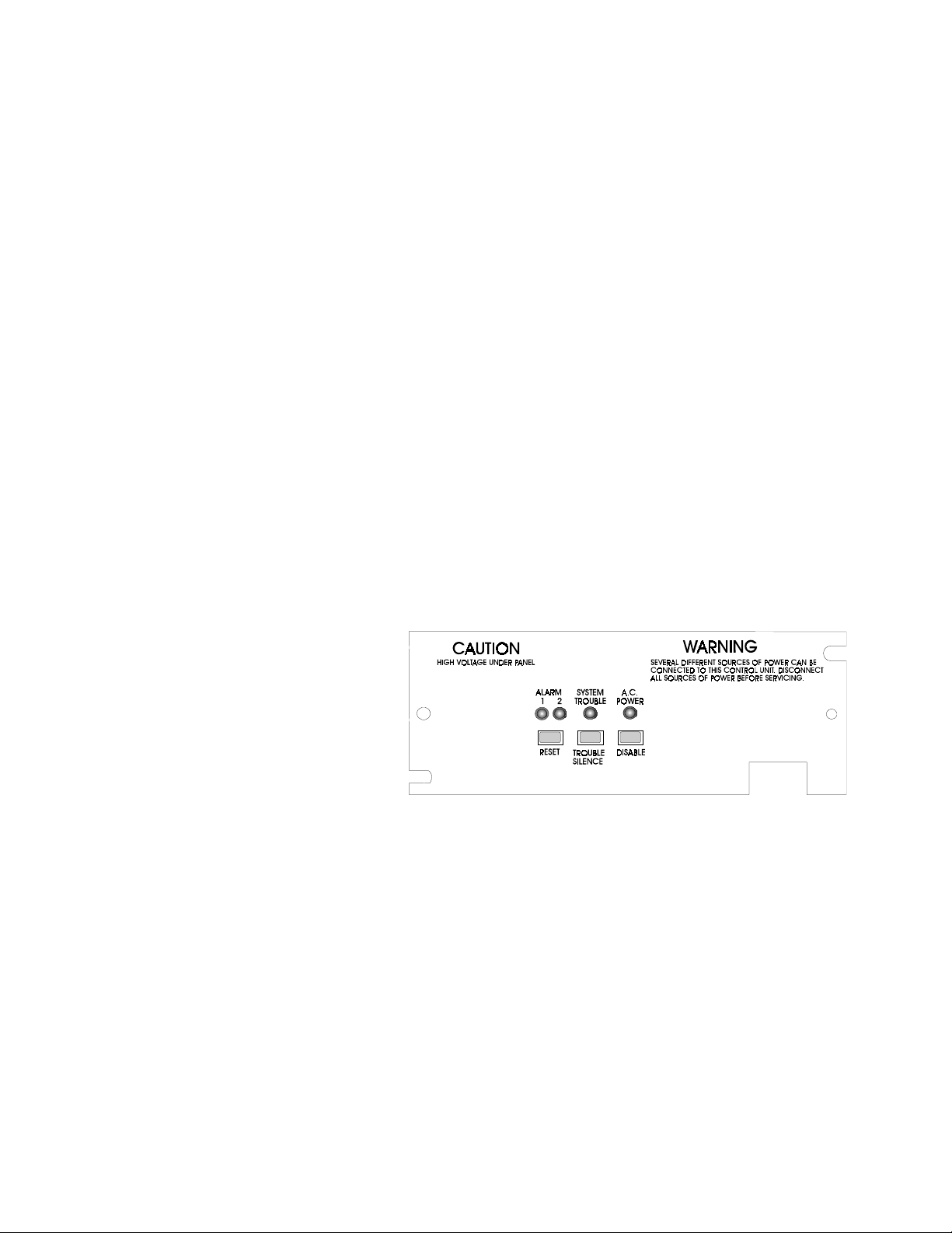
Controls and Indicators
RESET - The function of this switch is to reset the control panel and the smoke detectors provided the alarm
condition has been cleared. A trouble condition is indicated while this switch is depressed.
TROUBLE SILENCE - This latching, two-position switch, when pressed, will silence the pulsing audible
trouble signal. The trouble LED will continue to indicate a trouble condition. An intermittent tone will sound
when the trouble is corrected to indicate that this switch should be returned to its outward (normal) position.
DISABLE - This latching, two-position switch, when pressed, will prevent the activation of Notification
Appliances and the operation of the optional modules. The alarm LED(s) will continue to indicate the alarm
conditions. A trouble condition is indicated while this switch is in the off-normal position.
ALARM - Red LED(s) which indicate an alarm condition. The DISABLE switch will not effect the ALARM
LED(s).
TROUBLE - A yellow LED which is illuminated during a fault or abnormal operating condition.
AC - The green LED is on when the control panel is operating from the AC power source. Yellow and green
LEDs both flash to indicate below normal line voltage (brown-out). An extinguished green LED indicates
complete loss of AC power.
AUDIBLE TONE - An audible tone will sound to indicate the following:
• Alarm: A continuous sounding audible tone.
• Trouble: A pulsing audible tone signal having a short on time and long off time.
NORMAL STANDBY OPERATION
• All push button switches must
be in the normal outward
position.
• Green AC power indicator on
steady.
• Red ALARM indicator(s) off.
• Yellow TROUBLE indicator off.
ALARM CONDITION
• A red Alarm indicator will light.
• Alarm Notification appliances
are activated.
• Option module (remote station or supplementary alarm relay) is activated.
• Off-Normal Trouble Silence Switch: Indicated by an intermittent audible tone signal having a long on
time and short off time.
ALARM RESET
After locating and correcting the alarm condition, reset the control panel by pressing the RESET switch.
Return all switches to their normal positions.
Figure 2.1: Controls And Indicators
TROUBLE CONDITIONS
Activation of a trouble signal under normal operation indicates a condition that requires immediate correction. Contact your local service representative. The audible signal may be silenced by depressing the
TROUBLE SILENCE switch. The trouble LED will continue to flash.
MP-12/24 Fire Alarm Control Panel Document 15440:G 6/6/96
5
Page 6

Section Three:
Technical Specifications
All specifications are typical characteristics measured under nominal conditions at 25° C, unless otherwise specified.
System Power Requirements
MP-12/24 Operating voltage: 120 VAC, 60 Hz (standard).
MP-12/24 Current Draw: 0.5 A (maximum).
MP-12/24E Operating voltage: 220/240 VAC, 50/60 Hz
MP-12/24E Current Draw: 0.250 A (maximum).
Standby battery:
Voltage: (MP-12) 12 VDC; (MP-24) 24 VDC
Capacity: 2.5 to 7.0 AH (dependent on external loading).
Detection Loop
Operation: Style B (Class B).
Voltage: (MP-12) 8.6 to 12.2 VDC, ripple 0.65 Vp-p. (MP-24) 18 to 26.2 VDC, ripple 2.0 Vp-p.
Current required to ensure alarm: 20 mA (minimum)
Short circuit current: 40 mA - 10 mA
Supervision current: 5 mA
ELR: (MP-12) 2.2 K, 0.5 W; (MP-24) 4.7K, 0.5 W
Max resistance per side: 100 ohms.
Max total zone resistance: 200 ohms.
Two-wire Smoke Detectors
Head voltage, standby: MP-12, 11 VDC; MP-24, 23 VDC.
Total standby head current per zone: 2 mA peak
Minimum head current to ensure alarm: 20 mA
Maximum alarm current supplied to initiating devices, per zone: 40 mA - 10 mA.
Main Notification Appliance (bell) Circuits
Activation: By any zone alarm
Disconnect: By DISABLE switch
Operation: Style Y (Class B).
Notification Appliances: Use polarized, UL Listed, Notification Appliances with a minimum rated voltage
range of 9-15 VDC on MP-12 and 18-30 VDC on MP-24. Refer to the Fire•Lite Device Compatibility Document for a listing of compatible devices.
Nominal output voltage: (MP-12) 12 VDC; (MP-24) 24 VDC.
Output is
Output current: Total current to all external Notification Appliances cannot exceed: (MP-12) 1.0 A; (MP-24)
0.75 A.
Special Purpose Power
(full wave rectified DC, unregulated and unfiltered).
External Device Power
Regulated DC output: Resettable power primarily for four-wire smoke detectors and/or other low power
electronic devices. Maximum current available: 100 mA
Note: Size standby battery to include external loading.
Nominal voltage: (MP-12) 12 VDC; (MP-24) 24 VDC.
Battery Charger
Float type, turned off during alarm.
Float voltage setting: (MP-12) 13.8 VDC; (MP-24) 27.6 VDC. Automatic current limiting.
Note: Since battery charger is pulsed on and off, the charger output cannot be read with a voltmeter when
battery is not connected. A typical voltmeter would read approximately 8.5 V on the MP-12 and 16.5 V on the
MP-24.
6
MP12/24 Fire Alarm Control Panel Document 15440:G 6/6/96
Page 7

Optional Modules
The MP-12/24 will accept one of the following optional modules:
• Dry Alarm Contacts (MP-AC12; MP-AC24). Two Form-C rated 3 A @ 120 VAC and 30 VDC (resistive).
• Dry Alarm and Trouble Contacts (MP-AT12; MP-AT24). One Form-C Alarm and one Form-C Trouble,
both rated 3 A @ 120 VAC and 30 VDC (resistive).
• Remote Station Output Modules Models MP-TRT12 and MP-TRT24 output alarm and trouble. Models
MP-TR12 and MP-TR24 output alarm only.
Activation: By any zone alarm.
Disconnect: By an internal service switch, off-normal switch produces audible and visual trouble signals.
Remote Station Type: (MP-12) 12 VDC polarity reversal; (MP-24) 24 VDC polarity reversal.
Internal Resistance of Remote Station Output: (MP-12) 112 ohms; (MP-24) 660 ohms.
Ripple Voltage: Less than 2.0 Vp-p.
(Not suitable for separate transmission of both alarm and trouble signals to Remote Station).
System Control Switches
• Reset
• Trouble Silence
• Disable
System Status Indicators
• Red Zone alarm LED.
• Yellow system trouble LED.
• Green AC power LED.
Transformer
Harness
Connector
AC Circuit
Breaker
Neutral
Hot
{
Primary
AC Power
No Connection
+ - - + -
{
Notification
Appliance
Circuit
Initiating
Device
Circuits
{
Alarm
LEDs
Reset
Switch
Optional Module
Connector
Trouble
LED
Trouble
Silence
Switch
Disable
Switch
AC Power
LED
Battery
Connector
Figure 3.1: Component and Terminal Locations
MP-12/24 Fire Alarm Control Panel Document 15440:G 6/6/96
7
Page 8

Section Four:
Installation Instructions
The following procedures, diagrams, and instructions should be followed closely to avoid damage to the
control panel and its associated equipment. Reliability of the fire system depends upon proper installation and
maintenance.
Printed Circuit Board Removal
Carefully unpack the system. Open door and remove dress panel. Inspect the cabinet, door, printed circuit
board and other components for the possibility of shipping damage. It is recommended that the printed circuit
board assembly be removed from the cabinet and stored in a clean dry area while cabinet mounting and
wiring are taking place. To remove the assembly, simply remove the dress panel, unplug the transformer
cable, and slide the assembly from cabinet (see Figure 4.1).
Figure 4.1: PC Board, Cabinet and Dress Panel
Optional Module Installation
If an optional module is required, mount it to the main printed circuit board as follows:
• Refer to Figure 3.1 for location information.
• Remove the main printed circuit board as specified above.
• Snap the two plastic supports into the large holes on the optional module, flapped end towards
module.
• Install module on main printed circuit board. Check that each of the four connector pins of P2 mate
with their receptacle contacts on optional module.
Printed Circuit Board Installation
After the cabinet has been mounted and all field wiring has been run
back into the cabinet and reconnect the transformer cable. It is recommended that a pre-installation check be
made to validate that the system was received in good condition without shipping damage. To check system:
• Connect 120 VAC to Terminals 1 and 2 on the MP12/24 or 220/240 VAC to Terminals 1 and 2 on the
MP12E/MP24E.
• Connect batteries, observing polarity.
• Check system according to Section 5.
8
MP12/24 Fire Alarm Control Panel Document 15440:G 6/6/96
, slide the printed circuit board assembly
Page 9
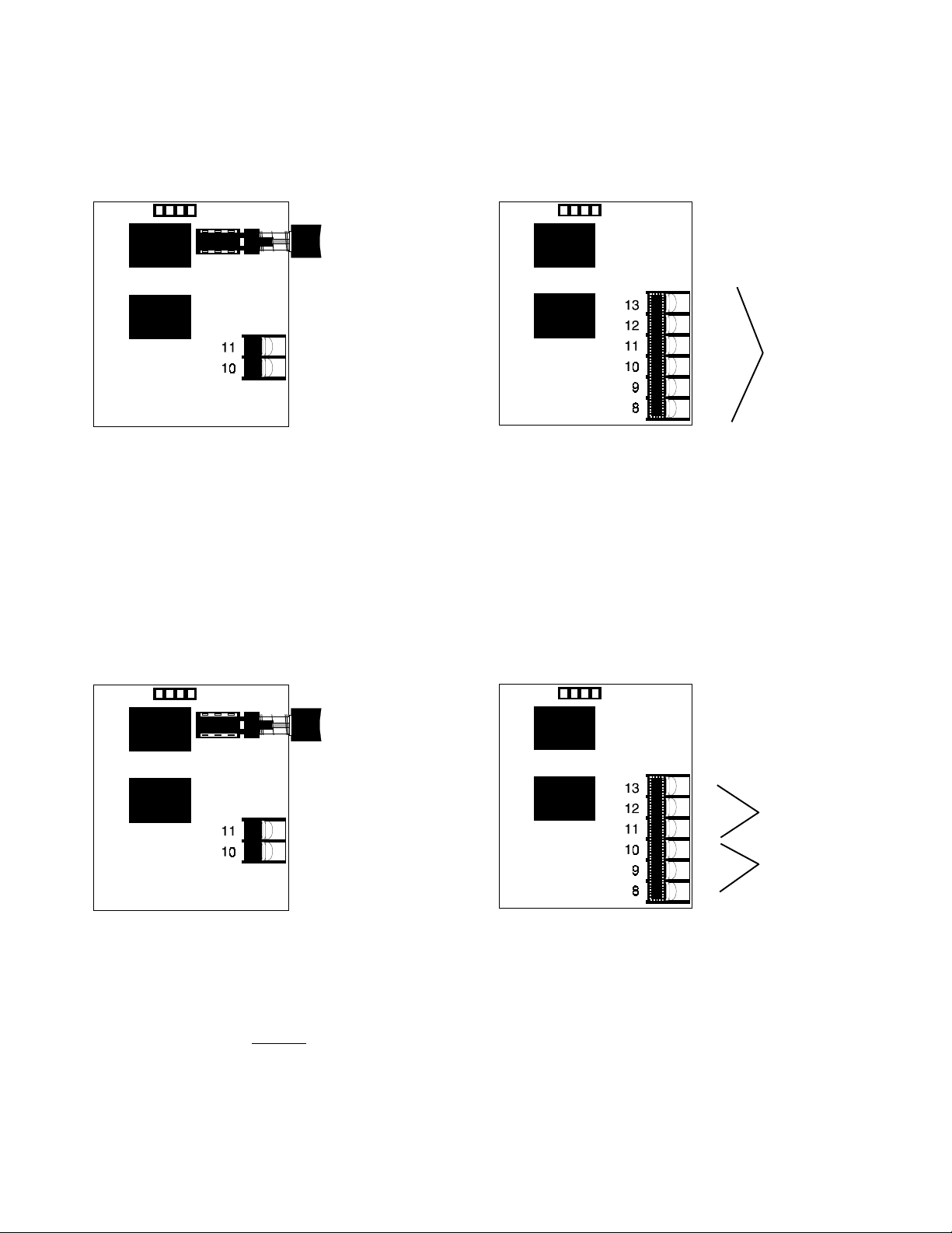
Figure 4.2: Optional Modules
MP-TR
Remote Station
disconnect switch
Reverse Polarity
+
-
Remote Station output.
Polarity shown is for
normal standby state.
Polarity reverses on
alarm.
Connect to compatible UL Listed polarity sensitive remote
station receiver, Fire•Lite RS-82 or equivalent. Output
signal: MP-12, 9 to 14 VDC; MP-24, 18 to 28 VDC.
Note 1: For wiring refer to UL power limited requirements.
Note 2: This circuit is suitable to leave the building.
Note 3: This output is power-limited.
MP-AC
NO #2
NC #2
Pole #2
Pole #1
NO #1
NC #1
Two sets
Form-C
alarm
contacts.
Rating: 3 A
resistive,
120 VAC/
30 VDC.
Note 1: For wiring refer to UL power limited requirements.
Note 2: Both sets of contacts must either be connected to
a non-power limited or a power limited circuit. Sets
of contacts cannot be mixed.
Note 3: Refer to the Protected Premises Unit label
(located on the system door) and mark the dry
contacts used as non power-limited circuits.
MP-TRT
Remote Station
disconnect switch
Reverse Polarity
Remote Station output.
+
-
Polarity shown is for
normal standby state.
Polarity reverses on
alarm. Output signal is
0 volts during nonalarm trouble condition.
Connect to compatible UL Listed polarity sensitive remote
station receiver, Fire•Lite RS-82 or equivalent. Output
signal: MP-12, 9 to 14 VDC; MP-24, 18 to 28 VDC.
Note 1: For wiring refer to UL power limited requirements.
Note 2: The MP-TRT module does not comply with the
requirement for separate trouble/alarm signal
transmission.
Note 3: This circuit is suitable to leave the building.
Note 4: This output is power-limited.
MP-AT
NO
NC
Pole
Pole
NC*
NO*
Alarm output
contacts.
Trouble output
contacts.
Note 1: *Indicates non-trouble state.
Note 2: All contacts rated 3 A, 120 VAC/30VDC.
Note 3: For wiring refer to UL power limited requirements.
Note 4: Both sets of contacts must be connected to a
non power-limited or a power limited circuit. Sets
of contacts cannot be mixed.
Note 5: Refer to the Protected Premises Unit label
(located on the system door) and mark the dry
contacts used as non power-limited circuits.
MP-12/24 Fire Alarm Control Panel Document 15440:G 6/6/96
9
Page 10
Field Wiring
All field wiring connections are made to the screw
type terminal blocks, located along the edges of the
To the ground stud located on the cabinet
next to the transformer assembly.
Power Limited circuit
Power Limited circuit
PC boards, as shown in wiring diagrams. Wiring
should be in accordance with National and/or Local
Codes for fire alarm systems. Use knockouts
provided on back and side of cabinet.
Neutral
Ground
AC Power Input
No connection
Hot
End-of-Line Resistor
(10K ohms) – mount
after the last device.
End-of-Line Resistor –
mount after the last device.
4.7K ohms (24V system)
2.2K ohms (12V system)
.
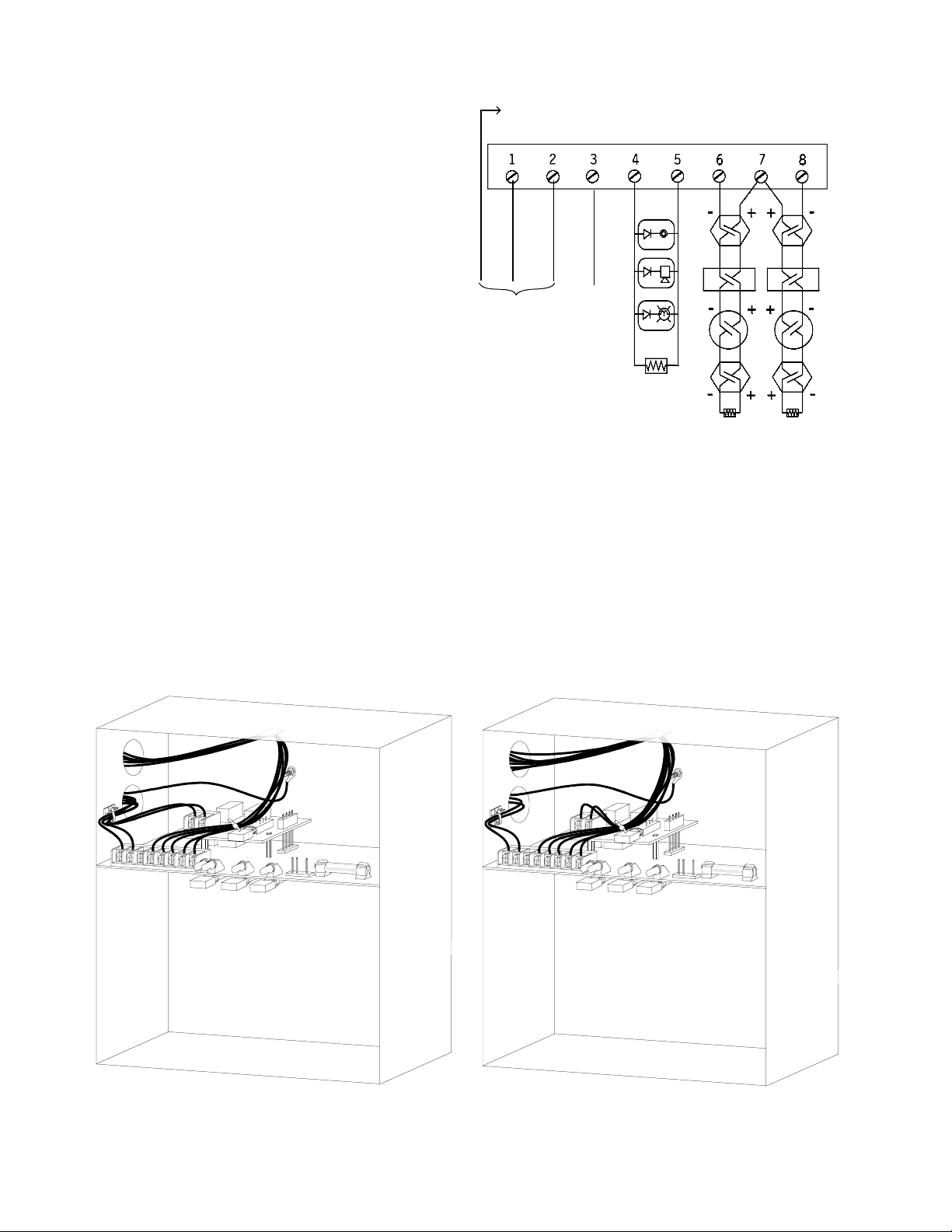
Figure 4.3: Main PC Board Wiring Diagram
UL Power Limited Wiring Requirements
Power limited and non-power limited circuit wiring must remain separated in the cabinet. All power limited
circuit wiring must remain at least 0.25" away from any non-power limited circuit wiring. Furthermore, all
power limited circuit wiring and non-power limited circuit wiring must enter and exit the cabinet through different knockouts and/or conduits. Create knockouts if necessary.
• For side knockouts, place the wire ties as shown in Figure 4.4.
• Use a lower knockout to run the wiring for non-power limited circuits and the upper knockout for
power limited circuits.
10
Module shown connected to
non power-limited circuit.
Figure 4.4: Typical wiring diagram for side knockouts
MP12/24 Fire Alarm Control Panel Document 15440:G 6/6/96
Module shown connected to
power-limited circuit.
Page 11

Power Limiting Notes Continued
• For back knockouts, place the wire ties as shown in Figure 4.5.
• Use a lower knockout to run the wiring for non-power limited circuits and the upper knockout for
power limited circuits.
Module shown connected to
non power-limited circuit.
Module shown connected to
power-limited circuit.
Figure 4.5: Typical wiring diagram for back knockouts
Alarm Initiating Devices
Wire all alarm initiating devices, including manual stations, heat detectors and smoke detectors, to zone
input terminals as shown in Figure 4.3. Refer to device data sheet for device connection information. Observe polarity when connecting polarized devices. Zone input terminals and polarity are:
Zone 1 Input: Terminal 7 positive, Terminal 6 negative.
Zone 2 Input: Terminal 7 positive, Terminal 8 negative.
All initiating devices connected to a given zone must be wired sequentially for proper supervision. Connect
the first device to the control panel, the second device connects to the first device, the third to the second
and so on. Remove the End-of-Line Resistor (ELR) from the control panel and install on terminals of the last
initiating device.
• Four-Wire Smoke Detectors
Power for four-wire smoke detectors may be obtained from terminals 5 (negative) and 7 (positive).
Supervise detector power with a listed end-of-line relay. Maximum current from terminals 5 and 7
should not exceed 100 mA. Two-wire detectors are recommended.
• Two-Wire Smoke Detectors
Compatible two-wire detectors can be connected directly to the zone input terminals. Polarity must
be observed. Two-wire detectors receive operating power from the zone terminals. Detector power
and alarm signals are transmitted through the same wires. The total peak standby detector current
per zone cannot exceed 2 mA. Compatible detectors are listed in the Device Compatibility Document.
• Sprinkler System Waterflow Alarm Devices
Normally open waterflow alarm devices may be connected to this panel provided the system is used
in conjunction with a mechanical water motor gong.
MP-12/24 Fire Alarm Control Panel Document 15440:G 6/6/96
11
Page 12

Notification Appliance Circuits
Connect the Style Y (Class B) Notification Appliance Circuits as shown in Figure 4.3. Use only polarized ULlisted Notification Appliances listed in the Device Compatibility Document. Size wire for a maximum voltage
drop of 1 VDC on 12-volt systems and 2 VDC on 24-volt systems. The following resistance table for solid
copper wire at 20° C may be helpful for sizing wire.
AWG GAUGE Ohms/1,000 FT.
18 6.385
16 4.016
14 2.525
12 1.588
10 0.9989
All Notification Appliances must be wired sequentially for proper supervision. The circuit's 10 KΩ ELR must
be removed from the control panel and connected to the circuit after the last Notification Appliance.
Regulated DC Output
Restorable primary power for detector and/or other low current electronic devices may be obtained from
Terminal 5 (-) and Terminal 7 (+). Do not connect inductive loads to these terminals. Nominal voltage output
is 12 VDC on 12-volt panels and 24 VDC on 24-volt panels. Maximum current available is 100 mA.
AC Power Connections
Primary power for the MP-12/24 is 120 VAC, 60 Hz, 0.50 A. Primary power for the MP-12/24E is 220/240
VAC, 50/60 Hz, 0.250 A. Connect terminal 1 (neutral) and 2 to a separate protected circuit, coming directly
from the line side of the main power feed to the building. No other equipment may be connected to the fire
alarm power circuit. Wire must run continuously, without disconnect devices, from the power source to the
fire alarm control panel. Overcurrent protection for this circuit must comply with article 760 of the National
Electrical Code and/or local codes. Use #14 AWG or larger wire with 600 V insulation.
Standby Battery Power
Battery selection and installation:
• Determine battery capacity from Table A.1.
• Read battery instruction sheet supplied with battery.
DANGER: Polarity must be observed when connecting battery.
• Connect battery cable to battery (Red wire to + terminal of battery. Black wire to - terminal of
battery).
• Route battery cable via 1/4" wide opening in the circuit board corner nearest P3. Do not allow
battery cable to be near heat-sinks on circuit board, since heat can damage the cable.
• Plug keyed female connector on end of battery cable onto terminal P3 of the circuit board.
CAUTION: Battery contains Sulfuric Acid which can cause severe burns to the skin and eyes and damage
to fabrics. In the event the battery leaks and contact is made with the Sulfuric Acid, immediately flush skin or
eyes with water for at least 15 minutes. For eyes, seek immediate medical attention. A good neutralizing
solution for Sulfuric Acid is water and household baking soda.
12
MP12/24 Fire Alarm Control Panel Document 15440:G 6/6/96
Page 13

Section Five:
Periodic Testing And Maintenance
To ensure proper and reliable operation, it is recommended that system inspection and testing be scheduled
monthly or as required by national and/or local fire codes. Testing should be done by a qualified services
representative if a malfunction is encountered.
Before testing:
1) Notify the fire department and/or central alarm receiving station if an alarm condition is transmitted.
2) Notify facility personnel of a test so that alarm sounding devices are ignored during the test period.
3) When necessary, activation of Notification Appliances can be prevented by pressing the DISABLE
switch.
Testing:
1) Activate a zone via an alarm initiating device and check that active Notification Appliances sound and
alarm LED lights. Reset system. Repeat for each zone.
2) Momentarily activate the following switches (one at a time) and check for a trouble signal:
• RESET
• DISABLE
3) Depress the TROUBLE SILENCE switch and check for an intermittent audible signal. Return TROUBLE SILENCE switch to normal position.
4) Momentarily open the following circuits one at a time and check for a trouble signal:
• Notification Appliance (bell) Circuit.
• Initiating Zone 1.
• Initiating Zone 2 (if employed).
5) If new batteries were installed, wait 48 hours before completing this step. Remove AC power, activate
zone and check that :
• the ALARM indicator lights.
• all active Notification Appliances sound.
Measure battery voltage while the Notification Appliances are sounding. Replace any battery with
terminal voltage less than 85% of rating. Reapply AC power and press RESET.
6) Return all switches to their normal outward positions. Notify fire department, central station and/or
building personnel that test is complete.
MP-12/24 Fire Alarm Control Panel Document 15440:G 6/6/96
13
Page 14

Section Six:
Troubleshooting Guide
Detailed acceptance testing procedures are beyond the scope of this manual. Such procedures must be
developed as part of the overall system installation. In each case, before the system is accepted into
service, it must meet the operating criteria established by the specifying engineer and endorsed by the
Authority Having Jurisdiction. Following is a checklist to aid in establishing operating criteria.
When full power is applied:
• The green power LED glows. No RED or YELLOW LEDs are on and no audible devices are sounding.
When an alarm is present:
• All activated alarm devices sound.
• The red alarm LED glows and the built-in audible device sounds steady.
When a trouble is present:
• The system trouble LED glows and the built-in audible device sounds while pulsing.
Troubleshooting Tips
• Don't panic. Calmly evaluate the symptoms.
• If more than one trouble is indicated, select a specific indication and troubleshoot it. It is better to
follow a logical sequence and not introduce any new problems.
• Prior to installation, check a new panel on the bench with ELRs whenever possible.
• On the job-site, determine as soon as possible if the problem is internal to the panel or in the external
circuits.
• Spare components (known to be good) are essential to fast, efficient troubleshooting.
• Follow the step by step procedures listed in this guide. Replacing components in a random manner
may cause additional damage to the system. Troubleshoot the component which has the trouble
indication and replace the component with a known good component.
• Always use voltage measurements when troubleshooting the panel.
• If you are unable to locate the problem by following these procedures, technical service is available
from the Fire•Lite Technical Services Department.
14
motpmySsisylanAmotpmySnoitcAlaidemeR
1 .ffoDELrewoPCA.
.ffoDELelbuorT
.noDELelbuorT
1 .54DdegamaD. .1 .draobtiucriCecalpeR
.1 .rewopniamfossoL .1 .rewopgnimocnikcehC
.2 tiucricdegamadroesufA1degamaD
.ffoDELrewoPCA.2
.rekaerb
.3 .DEL73DdegamaD .1 .draobtiucricecalpeR
.4 .ylppusrewopdegamaD .1 .sgnidaeregatlovrof1ProtcennockcehC
MP12/24 Fire Alarm Control Panel Document 15440:G 6/6/96
.1 .rekaerbtiucricroesufA1ecalpeR
.remrofsnartrewopecalpeR:egatlovoN
.2 .CAstlov82.xorppa5-1P/2-1P
Page 15

MP-12/24 Fire Alarm Control Panel Document 15440:G 6/6/96
15
Page 16

Symptom Symptom Analysis Remedial Action
4. Zone always
in alarm.
1. Defective detector. 1. Disconnect field wiring and install
ELRs. If panel resets to normal, check for
damaged or incorrectly wired detector
and replace it.
2. Typical zone supervisory current 5 mA
(approximately)
2. Shorted heat detector. 1. Locate detector and replace.
3. Activated station 1. Locate detector and replace.
4. Too many smoke
1.Reduce number of detectors.
detectors on zone.
5. Damaged circuit card. 1. Remove zone wires and install ELR
resistor.
2. If trouble clears, check field wires.
3. If trouble does not clear, replace
circuit board.
Appendix A: Battery Selection Guide
A 2.5 AH battery will power the control panel plus compatible two-wire detectors in the non-alarmed standby
mode for 60 hours and then operate the Notification Appliances for 5 minutes. If the control panel is providing
power to external devices other than two-wire detectors and Notification Appliances, use the following table to
determine the required battery capacity. Record battery information on the door label.
25 mA
Single
Zone
30 mA
Two
Zone
Standby
Requirements
24 hour Standby,
5 minute alarm,
NFPA 72A & 72D
60 hour Standby,
5 minute alarm,
NFPA 72B & 72C
24 hour Standby,
5 minute alarm,
NFPA 72A
60 hour Standby,
5 minute alarm,
NFPA 72B & 72C
2.5 AH 4.0 AH 4.5 AH 5.0 AH 5.5 AH 6.0 AH 7.0 AH
0.058 A 0.108 A 0.125 A 0.141 A 0.158 A 0.175 A 0.191 A
0.008 A 0.028 A 0.035 A 0.041 A 0.048 A 0.055 A 0.061 A
0.053 A 0.103 A 0.120 A 0.136 A 0.153 A 0.170 A 0.186 A
0.003 A 0.023 A 0.030 A 0.036 A 0.043 A 0.050 A 0.056 A
TABLE A.1: Maximum Current Available for Various Battery System Combinations.
1) The table shows the maximum current available for the operation of external power consuming devices connected
to the control panel for different capacity standby batteries.
2) Power consuming devices include 4-wire detectors, end-of-line relays, remote trouble signal devices (bell, horns
and lamps), remote station loading on MP-TR12/24 module, and any device powered from terminals 5 and 7.
3) Table A.1 is based on 80% battery use.
4) Batteries are float charged during normal standby operation. A discharged battery will charge and obtain its float
voltage within 48 hours.
5) Batteries available from Fire•Lite:
– PS-1242 12 Volt, 4.2 AH.
– PS-1270 12 Volt, 7.0 AH.
6) Required battery voltage is 12V for the MP-12; 24V for the MP-24.
Compatible Detectors
See the Device Compatibility Document (Document 15384).
16
MP12/24 Fire Alarm Control Panel Document 15440:G 6/6/96
Page 17

NOTES
MP-12/24 Fire Alarm Control Panel Document 15440:G 6/6/96
17
Page 18

NOTES
18
MP12/24 Fire Alarm Control Panel Document 15440:G 6/6/96
Page 19

NOTES
MP-12/24 Fire Alarm Control Panel Document 15440:G 6/6/96
19
Page 20

Limited Warranty
Fire-Lite® warrants its products to be free from defects in materials and workmanship
for eighteen (18) months from the date of manufacture, under normal use and service.
Products are date stamped at time of manufacture. The sole and e xclusive ob ligation
of Fire-Lite® is to repair or replace, at its option, free of charge for parts and labor, any
part which is defective in materials or workmanship under normal use and service.
For products not under Fire-Lite® manufacturing date-stamp control, the warranty is
eighteen (18) months from date of original purchase by Fire-Lite®'s distributor unless
the installation instructions or catalog sets forth a shorter period, in which case the
shorter period shall apply. This warranty is void if the product is altered, repaired or
serviced by anyone other than Fire-Lite® or its authorized distributors or if there is a
failure to maintain the products and systems in which they operate in a proper and
workable manner . In case of defect, secure a Return Material Authorization f orm from
our customer service depar tment. Return product, transportation prepaid, to Fire-
Lite®, One Fire-Lite Place, Northford, Connecticut 06472-1653.
This writing constitutes the only warranty made by Fire-Lite® with respect to its products.
Fire-Lite® does not represent that its products will prevent any loss by fire or otherwise,
or that its products will in all cases provide the protection for which they are installed
or intended. Buyer acknowledges that Fire-Lite® is not an insurer and assumes no
risk for loss or damages or the cost of any inconvenience, transpor tation, damage,
misuse, abuse, accident or similar incident.
Fire-Lite® GIVES NO WARRANTY, EXPRESSED OR IMPLIED, OF
MERCHANT ABILITY, FITNESS FOR ANY P ARTICULAR PURPOSE, OR O THERWISE
WHICH EXTEND BEY OND THE DESCRIPTION ON THE FACE HEREOF. UNDER
NO CIRCUMSTANCES SHALL Fire-Lite® BE LIABLE FOR ANY LOSS OF OR
DAMA GE T O PROPER TY, DIRECT, INCIDENTAL OR CONSEQUENTIAL, ARISING
OUT OF THE USE OF, OR INABILITY TO USE Fire-Lite® PRODUCTS.
FURTHERMORE, Fire-Lite® SHALL NOT BE LIABLE FOR ANY PERSONAL INJUR Y
OR DEATH WHICH MAY ARISE IN THE COURSE OF, OR AS A RESULT OF,
PERSONAL, COMMERCIAL OR INDUSTRIAL USE OF ITS PRODUCTS.
This warranty replaces all previous warranties and is the only warranty made by Fire-
Lite®. No increase or alteration, written or verbal, of the obligation of this warranty is
authorized.
"Fire-Lite" is a registered trademark.
One Fire-Lite Place, Northford, CT 06472
Phone: (203) 484-7161
FAX: (203) 484-7118
Technical Publishing Document WARFBG-D.P65 11/04/98
 Loading...