


User’s Guide
www.fetco.com
CBS-62H Coffee Brewer
Maritime Version
Rated IP44
Table of Contents
Contact Information ........................................... |
2 |
Service............................................................... |
7 |
Product Description/Features............................ |
2 |
Wiring Diagram................................................ |
12 |
Specifications..................................................... |
2 |
Dispenser Parts ............................................... |
13 |
Dimensions & Utility Connections...................... |
3 |
Brewer Parts.................................................... |
14 |
Installation.......................................................... |
4 |
Troubleshooting............................................... |
17 |
Operating Procedures ....................................... |
6 |
|
|
FETCO® LUXUS® and Driven To Pioneer Innovation™ are trademarks or trade names of Food Equipment Technologies Company.
© 2009 Food Equipment Technologies Company |
Part # P107 |
REV. 001 |

Contact Information
FETCO |
Phone: (800) 338-2699 (US & Canada) |
Food Equipment Technologies Company |
(847) 719-3000 |
600 Rose Road |
Fax: (847) 719-3001 |
Lake Zurich • IL • 60047-0429 • USA |
Email: sales@fetco.com |
|
|
Internet: www.fetco.com |
techsupport@fetco.com |
Product Description/Features
• Maritime Version with IP44 Ingress Protection Rating |
• Open type, leak free dispense system |
• 3 gallon, thermal, portable, all stainless steel dispensers |
• Brew basket double safety locks |
• Stainless steel, gourmet size brew baskets |
• Two level tank drain system |
• Fully automatic, with electronic temperature control |
• Total serviceability from the front |
|
|
|
|
|
|
|
|
|
|
Specifications |
|
|
|
|
|
|
|||||||
Brew Volume: |
|
|
|
|
|
|
|
|
|
|
|
|
|
|
Temperature: |
|
|
|
|
||
|
|
|
|
|
|
|
|
|
|
|
|
|
|
|
|
|
|
||||
Full Batch |
|
3 gal. (11.4 lit.) |
|
|
|
|
|
|
|
|
|
205°F inside water tank (at sea level) |
|||||||||
Half Batch 1.5 gal. (5.7 lit.) |
|
|
|
|
|
|
|
|
|
195°F ± 5° at sprayhead |
|
||||||||||
Brew Time: |
|
|
|
|
|
|
|
|
|
|
|
|
|
|
Bypass Range: 0 to 33% |
|
|||||
Full Batch |
|
5 - 5.5 min. |
|
|
|
|
|
|
|
|
|
|
(Factory set at 0% unless specified) |
|
|||||||
Half Batch |
|
2.5 – 2.75 min. |
|
|
|
|
|
|
|
|
|
|
|
|
|
|
|
||||
(Allow an extra 2-4 minutes for coffee to finish dripping) |
|
|
|
|
|
Water Requirements: |
|
||||||||||||||
Coffee Filter Size: 20” X 8” – Product # F004 |
|
|
|
|
|
|
20-75 psig, 2 gpm |
|
|||||||||||||
|
|
|
|
|
|
|
|
|
|
|
|
||||||||||
|
|
|
18” X 7½” - optional half batch |
Product # F005 |
|
|
|
|
|
|
|
||||||||||
Weights and Capacities |
|
|
|
|
|
|
|
Dispenser |
Dispenser |
|
|
|
|
||||||||
Brewer |
|
Weight |
|
|
Water tank |
|
|
Weight |
|
Total Weight Brewer |
|||||||||||
Model |
|
(empty) |
|
Capacity & Weight |
|
|
(filled) |
Weight, ea. |
Filled, ea. |
|
& Dispensers, Filled |
||||||||||
CBS-62H |
|
195 lbs. |
|
14 gal. |
|
116.2 lbs. |
311.2 lbs. |
18 lbs. |
42.5 lbs. |
|
397 lbs. |
||||||||||
Electrical Configuration and Brewing Efficiency |
|
|
|
|
|
|
|||||||||||||||
|
|
|
|
|
|
|
|
|
|
|
|
|
|
|
|
|
|
||||
Electrical |
|
Heater |
|
|
Voltage |
|
|
|
|
|
|
|
|
Maximum |
|
Batches per Hour |
|||||
Code |
|
Configuration |
Connection |
|
Phase |
|
Wires |
KW |
Amp draw |
Cold Water |
|
Hot Water |
|||||||||
|
|
|
|
|
|
|
|
|
|
|
|
|
|
||||||||
C62186MIP |
|
6 X 4000 W |
|
440 |
|
three |
|
3 + ground |
20.1 |
27.4 |
17.3 |
|
18.0 |
||||||||
|
|
|
|
|
|
|
480 |
|
three |
|
3 + ground |
24.1 |
29.7 |
18.0 |
|
18.0 |
|||||
C62196MIP |
|
3 X 4000 W |
|
440 |
|
three |
|
3 + ground |
10.1 |
13.7 |
8.6 |
|
18.0 |
||||||||
|
|
|
|
|
|
|
480 |
|
three |
|
3 + ground |
12.1 |
14.9 |
9.9 |
|
18.0 |
|||||
2
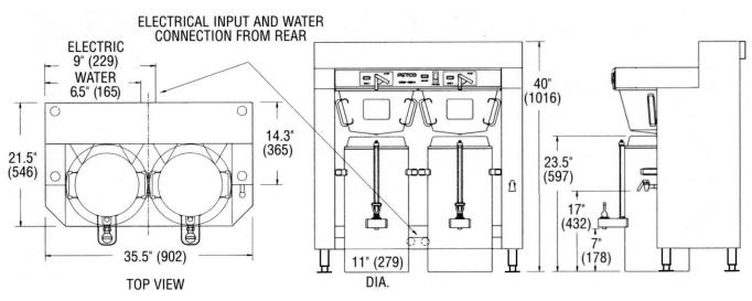
Dimensions & Utility Connections
3
Installation
(For Qualified Service Technicians Only)
Keys To A Successful Installation
If not installed correctly by qualified personnel, the brewer may not operate properly and damage may result. Damages resulting from improper installation are not covered by the warranty.
Here are the key points to consider before installation:
Electrical:
The power switch has a built-in circuit breaker. To reset it, turn to the “off” position, and then back to the “on” position.
The electrical drawing for the brewer is located on the inside of the lower cover.
Plumbing:
This equipment is to be installed to comply with the applicable federal, state, or local plumbing codes. The water line must be flushed thoroughly prior to connecting it to the brewer to prevent debris from contaminating the machine.
Verify that the water line will provide at least 2 gallons per minute before connecting it to the brewer.
Installation Instructions
Brewer Setup
1.Review the Dimensions for the unit you are installing. Verify that the brewer will fit in the space intended for it, and that the counter or table will support the total weight of the brewer and dispensers when filled.
2.The brewer’s legs are shipped inside the brew baskets. Remove the brew basket(s) and the coffee dispenser(s). Place the brewer on its back and screw in the legs.
3.Place the brewer on the counter or stand. Warning: Legs are to be adjusted for
4. |
When the brewer is in position, level it front to back as |
leveling the brewer only. Do not use |
5. |
well as side-to-side by adjusting the legs. |
for height adjustment or extend them |
Mark the surface of the counter with the location of the |
higher than necessary. |
|
|
mounting holes in the legs. |
|
6.Drill ¼” diameter holes in the counter and secure the legs to the counter with bolts and nuts (not included).
7.Remove the lower cover to access the water and electrical connections.
Server Ring Installation
1.Place a LUXUS dispenser in the proper position under each brew basket.
2.Mark the surface of the counter top with the circular outline of the dispenser bottom.
3.Remove the dispenser and place a mark at the exact center of the circle.
4.Drill a ¼” hole in the center of the circle.
5.Insert the threaded stud on the bottom of the server ring into the hole and secure it with the wing nut provided.
6.To install the server rings away from the brewer, place the dispensers in the desired location and follow steps 2 through 5.
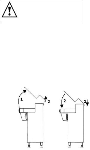
Top Cover Instructions
1.Remove all screws. The back edge of the top cover fits tightly over the vents on the back of the brewer. Carefully lift the front of the cover up and back.
2.Once the cover is at a 45° angle, it can be lifted completely off.
1.To replace the cover, hold the cover at approximately a 45° angle and place the back edge over the vents on the back of the brewer.
2.Lower the front of the cover while pulling it over the top of the brewer. The cover should flex slightly. Install all screws.
4
Water Connection
1.The water inlet is a 3/8 inch male flare fitting. Insert the water line through the splash-proof grommet on the back of the brewer and attach it to the fitting.
2.The brewer can be connected to a cold or hot water line. Cold water is preferred for best coffee flavor, but hot water will allow for faster recovery times.
3.Install a water shut off valve near the brewer to facilitate service. If an in-line water filter is used, it should be installed after the water shut off valve and in a position to facilitate filter replacement.
4.Flush the water supply line and filter before connecting it to the brewer.
5.Verify that the water line will provide at least 2 gallons per minute and that the water pressure is between 20 and 75 psig.
Electrical Connections
1.Verify that the actual voltage at the electrical service connection is compatible with the specifications on the brewer’s serial number label.
2.The temperature and water tank fill level are pre-set at the factory. There is no need to turn off the heaters during the installation process. The control board disables the heaters until the tank is full of water. The heating process will start automatically when the tank has filled.
3.A fused disconnect switch or circuit breaker on the incoming power line must be conveniently located near the brewer, and its location known to the operators.
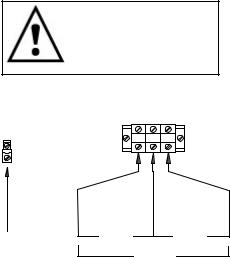
4.The body of the brewer must be grounded to a suitable ground. A ground lug is provided in the brewer next to the terminal block. Use only 10 gauge copper wire.
5.Electrical connections must be secured in-place within the unit to meet national and local standards.
6.Finally, connect the incoming power wires to the terminal block in accordance with applicable codes.
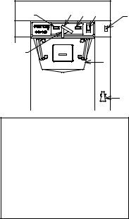
Final Setup
Warning: To prevent electrical shock, this unit must be properly grounded.
GROUND |
|
|
|
LUG |
L1 |
L2 |
L3 |
|
GROUND |
480V |
480V |
WIRE |
|
480V |
1.Turn on the incoming water supply line and inspect both inside and outside of the brewer for leaks in all fittings and tubes
2.Turn on the incoming power.
3.Turn on the brewer’s main power switch.
4.Within 6 seconds, the hot water tank will begin filling until the probe at the top of the tank senses the water.
5.The control board will disable the heaters until the tank is full.
6.The brewer will be ready for operation as soon as the ready light comes on to show that the water tank is up to temperature. The time required to reach brewing temperature will vary according to the electrical configuration ordered.
7.Review the Operating Instructions. Brew one full batch (water only) on each side to confirm proper fill levels. The brewer is factory set with water only (no coffee) to dispense the correct amount of water.
8.Re-attach the covers after one final inspection for leaks. Look closely in the top of the brewer at the dispense fittings during this inspection.
Operating Training
Review the operating procedures with whoever will be using the brewer. Pay attention to the following areas:
1.Always pre-heat the dispensers before the first use of each day by filling them half way with hot water, and letting them stand for at least 15 minutes.
2.Don't remove the brew basket until it has stopped dripping.
3.Make sure the dispenser is empty before brewing into it.
4.Show how to attach covers, close, and or secure the thermal dispensers for transporting.
5.Show the location and operation of the water shut off valve as well as the circuit breaker for the brewer.
6.Steam from the tank will form condensation in the vent tubes. This condensation will drip into and then out of the brew baskets. 1/4 cup discharging overnight is possible. Place an appropriate container under each brew basket when not in use.
7.We recommend leaving the power to the brewer on overnight. The water tank is well insulated and will use very little electricity to keep the tank hot. Leaving the brewer in the on position will also avoid delays at the beginning of shifts for the brewer to reach operating temperature.
5
Operating Procedures |
|
|
|
|
|
|
1. Turn brewer on/off switch (E) to the on position |
|
|
|
|
|
|
• The power switch will illuminate to indicate that the brewer has |
G |
|
B |
F |
E |
|
power and is operating. |
|
A |
||||
• When the ready light (F) illuminates, the brewer is fully up to |
|
|
STOP |
POWER |
|
|
|
|
R |
|
|
|
|
|
|
BREW |
READY |
|
|
|
temperature. The amount of time required to gain full operating |
|
|
|
|
|
|
temperature will vary depending on the electrical configuration |
C |
CAUTION |
|
|
|
|
|
AFTER |
|
|
|
||
|
HOT LIQUID |
|
|
|
||
|
|
BEFOR |
|
|
|
|
|
|
BREW |
|
|
|
|
that was ordered, and the temperature of the incoming water. |
|
MUSTMAKEBESUREIN |
|
D |
|
|
|
|
MAKE |
|
|
||
|
|
|
REMOVE BREW |
|
|
|
2. Pre-heat the dispensers. |
|
|
|
|
|
|
This step is very important to the overall success of the brewing |
|
|
|
|
|
|
operation. FETCO avoids the damaging affects of heat on fresh brewed |
|
|
|
|
|
H |
coffee by using highly insulated dispensers. The dispenser must be pre- |
|
|
|
|
|
|
heated with hot water from the brewer. This preheating process ensures |
Legend: |
|
|
|
|
|
that the coffee in the first brew starts out hot. Significant heat loss will |
|
|
|
|
|
|
occur when brewing coffee into a cold dispenser. Preheating is not |
A-Full/half batch switch |
|
||||
required for subsequent brews unless the dispenser remains empty for an |
B-Brew lever |
|
|
|
||
extended period of time and has cooled down. |
C-Safety bar |
|
|
|
||
• Slide the empty brew basket(s) (D) into their rails and put the |
D-Brew basket |
|
|
|
||
empty dispenser(s) in position under the basket for preheating. |
E-On/off switch |
|
|
|
||
Select the half batch mode, (A) if you have this option. |
F-Ready light |
|
|
|
||
G- Brew light |
|
|
|
|||
• When the ready light illuminates, start a brew cycle by rotating the |
|
|
|
|||
H- Hot water faucet |
|
|||||
brew lever (B) to the brew position. This starts clean hot water |
|
|||||
|
|
|
|
|
|
|
flowing into the brew basket and then into the dispenser. |
|
|
|
|
|
|
•Stop the cycle when each dispenser is approximately 1/2 full by moving the brew lever to the off position. This interrupts the brew cycle and resets the brewer .
•Let the dispensers stand 10-15 minutes, or until use, to allow the heat from the water to be absorbed by the dispensers.
3.Remove the brew baskets from the brewer when you are certain that the flow of hot water has stopped from the bottom of the basket.
•H model brewers will have a safety bar (C) in front of the brew basket to make removing the brew basket a 2-handed operation. This was done to help draw attention to the basket so the operator will notice any residual hot water or coffee.
•Place a paper filter in each basket to be used. Pour into the paper filter the appropriate amount of premeasured, ground coffee. The amount of coffee used will depend on your personal tastes and the recommendation of your roaster.
•Slide the brew basket back into the rails on the brewer. Insure the latch is outside of the basket.
4.Carefully drain any coffee or preheating water from the dispensers through the faucets before starting a coffee brewing cycle.
•Overflowing of the dispensers may result if the dispensers are not completely empty when the brew cycle begins. Verify by opening the faucet over an appropriate container or drain. The last several cups cannot be seen in the sight gauge tube.
•CAUTION: both the coffee or water may still be hot enough to cause burns, so be careful when draining the dispensers
5.Place the thermal dispenser(s) in position under the brew baskets.
•Ensure that the brew funnel is in place, the dispenser is empty, the faucet is closed, and the vent cap on the sight gauge is open.
•The twist lock cover is for transporting the dispenser only. It must be removed before placing the dispenser under the brew basket.
6.Start the brew cycle in the same manner used to start the water used to preheat the dispensers.
•It will not be necessary to interrupt the cycle while brewing coffee. The brewer will return to the stopped and ready status automatically.
•It is normal for the ready light to go out after the start of the brew cycle. On twin brewers, there is enough hot water in the brewer to support a second brew, even if the ready light is off. After brewing on both sides, you must wait for the ready light to come back on.
•The electrical configuration and the electrical power connected to the brewer will determine how long before the ready light comes back on for the next brew.
6
 Loading...