


User’s Guide
www.fetco.com
Models:
CBS-2031ee CBS-2032ee
CBS-2041ee CBS-2042ee
CBS-2032ee
CBS-2042ee
CBS-2041ee
CBS-2031ee
NOTICE TO INSTALLER: Please leave this book with the machine.
Table of Contents
Contact Information ........................................................ |
2 |
Programming .................................................................. |
9 |
Description & Features ................................................... |
2 |
Batch Settings............................................................. |
9 |
Specifications.................................................................. |
2 |
Temperature Settings ............................................... |
10 |
Requirements.............................................................. |
2 |
Advanced Settings and Diagnostics ......................... |
10 |
Weights and Capacities .............................................. |
2 |
Error Codes .................................................................. |
12 |
Electrical Configuration and Brewing Efficiency ......... |
3 |
Service and Support..................................................... |
13 |
Dimensions & Utility Connections................................... |
4 |
Cleaning & Maintenance .............................................. |
13 |
Installation....................................................................... |
6 |
Parts ............................................................................. |
14 |
Operating Instructions .................................................... |
8 |
|
|
FETCO®, LUXUS®, EXTRACTOR® and Driven To Pioneer Innovation™ are trademarks or trade names of Food Equipment Technologies Company.
© 2008 Food Equipment Technologies Company |
Part # P100 January 23, 2008 |

Contact Information
FETCO® |
Phone: (800) 338-2699 (US & Canada) |
Food Equipment Technologies Company |
(847) 719-3000 |
600 Rose Road |
Fax: (847) 719-3001 |
Lake Zurich • IL • 60047-0429 • USA |
Email: sales@fetco.com |
|
|
Internet: www.fetco.com |
techsupport@fetco.com |
Description & Features
The CBS-2030ee and CBS-2040ee series brewers feature our patented intermittent spray over technology, which works like this:
The following variables are programmed for each batch size:
Brew volume |
Prewet percent (Percentage of the brew volume) |
Brew time |
Prewet delay (The time between prewetting and the brew cycle.) |
|
Drip delay (The time that the brew light continues to flash after the brew cycle.) |
Using these variables, the software calculates how much water to use for prewetting, and brewing. The total brew time is divided into several 30 second cycles. Within these cycles, the software calculates how long to spray water over the coffee grounds, and how long to pause before the next cycle begins.
Features
Two fully programmable batch sizes per side |
Cascading Spray Domes |
Adjustable prewetting cycle |
Water hardness detection |
Brew at temperature protection |
User selectable"ECO" power saver |
|
|
|
|
|
Specifications |
|
|
|||
Requirements |
|
|
|
|
|
|
|
|
||
Water Requirements: |
|
|
|
|
Electrical: See electrical configuration chart. |
|||||
CBS-2031ee: 20-75 psig, ½ gpm |
|
|
|
|
|
|||||
CBS-2032ee: 20-75 psig, 1 gpm |
|
|
Coffee Filters: 13” X 5 ” FETCO Product # F002 |
|||||||
CBS-2041ee: 20-75 psig, 1 gpm |
|
|
|
|
|
|
||||
CBS-2042ee: 20-75 psig, 1 ½ gpm |
|
|
|
|
|
|||||
Weights and Capacities |
|
|
|
|
|
|
||||
Brewer |
Weight |
|
Water tank |
Weight |
|
Dispenser |
Dispenser |
Total Weight Brewer |
||
Model |
(empty) |
|
Capacity & Weight. |
(filled) |
|
Weight, ea. |
Filled, ea.. |
& Dispensers, Filled |
||
CBS-2031ee |
32 lbs. |
|
3.0 gal. |
|
25 lbs. |
57 lbs. |
|
4.4 lbs. |
11 lbs. |
68 lbs. |
CBS-2032ee |
44 lbs. |
|
5.4 gal. |
|
45 lbs. |
89 lbs. |
|
4.4 lbs. |
11 lbs. |
111 lbs. |
CBS-2041ee |
40 lbs. |
|
4.2 gal. |
|
35 lbs. |
75 lbs. |
|
8 lbs. |
16 lbs. |
91 lbs. |
CBS-2042ee |
53 lbs. |
|
7.4 gal. |
|
61 lbs. |
114 lbs. |
|
8 lbs. |
16 lbs. |
146 lbs. |
2
Electrical Configuration and Brewing Efficiency
USA & Canada
CBS-2031ee
3.0 liters per batch
Electrical |
Heater |
Voltage |
|
|
|
Maximum |
Batches per Hour* (max 11) |
|
Config. Code |
Configuration |
(AC) |
Phase |
Wires |
KW |
Amp draw |
Cold Water |
Hot Water |
E31015E |
1 X 2.3 KW |
120 |
single |
2 + ground |
2.4 |
19.7 |
7.4 |
11.0 |
CBS-2032ee |
|
|
|
|
|
|
3.0 liters per batch |
|
Electrical |
Heater |
Voltage |
|
|
|
Maximum |
Batches per Hour* (max 22) |
|
Config. Code |
Configuration |
(AC) |
Phase |
Wires |
KW |
Amp draw |
Cold Water |
Hot Water |
E32015E |
2 X 3 KW |
120/208 |
single |
3 + ground |
4.6 |
22.4 |
14.6 |
22.0 |
|
|
120/220 |
|
|
5.1 |
23.7 |
16.3 |
22.0 |
|
|
120/240 |
|
|
6.1 |
25.8 |
19.4 |
22.0 |
CBS-2041ee |
|
|
|
|
|
|
1.0 gallon per batch |
|
Electrical |
Heater |
Voltage |
|
|
|
Maximum |
Batches per Hour* (max 11) |
|
Config. Code |
Configuration |
(AC) |
Phase |
Wires |
KW |
Amp draw |
Cold Water |
Hot Water |
E41016E |
1 X 2.3 KW |
120 |
single |
2 + ground |
2.4 |
19.7 |
5.9 |
11.0 |
CBS-2042ee |
|
|
|
|
|
|
1.0 gallon per batch |
|
Electrical |
Heater |
Voltage |
|
|
|
Maximum |
Batches per Hour* (max 22) |
|
Config. Code |
Configuration |
(AC) |
Phase |
Wires |
KW |
Amp draw |
Cold Water |
Hot Water |
E42016E |
2 X 3 KW |
120/208 |
single |
3 + ground |
4.6 |
22.4 |
11.5 |
22.0 |
|
|
120/220 |
|
|
5.1 |
23.7 |
12.9 |
22.0 |
|
|
120/240 |
|
|
6.1 |
25.8 |
15.4 |
22.0 |
* Based on standard factory settings: 4.0 minute brew time; 0% prewet; 200 F water.
3
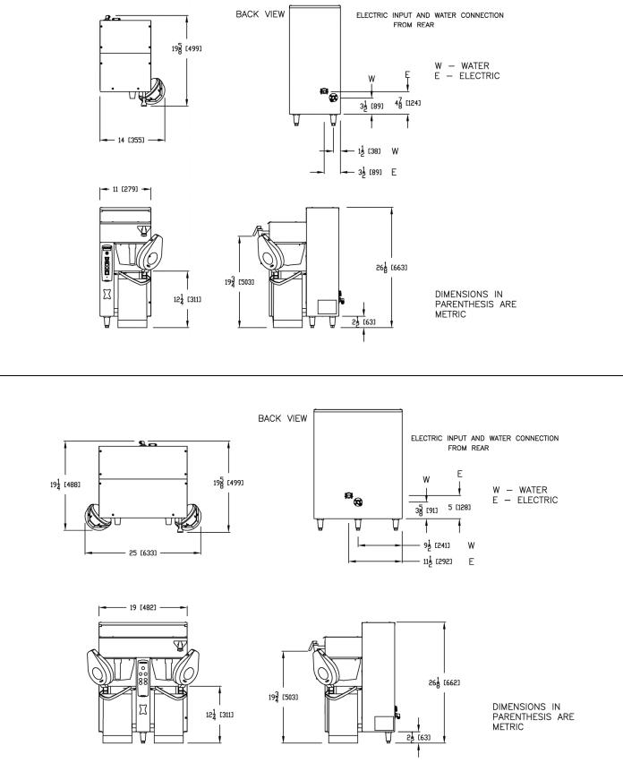
Dimensions & Utility Connections
CBS-2031ee
DWG 201141-000
CBS-2032ee
DWG 201142-000
4
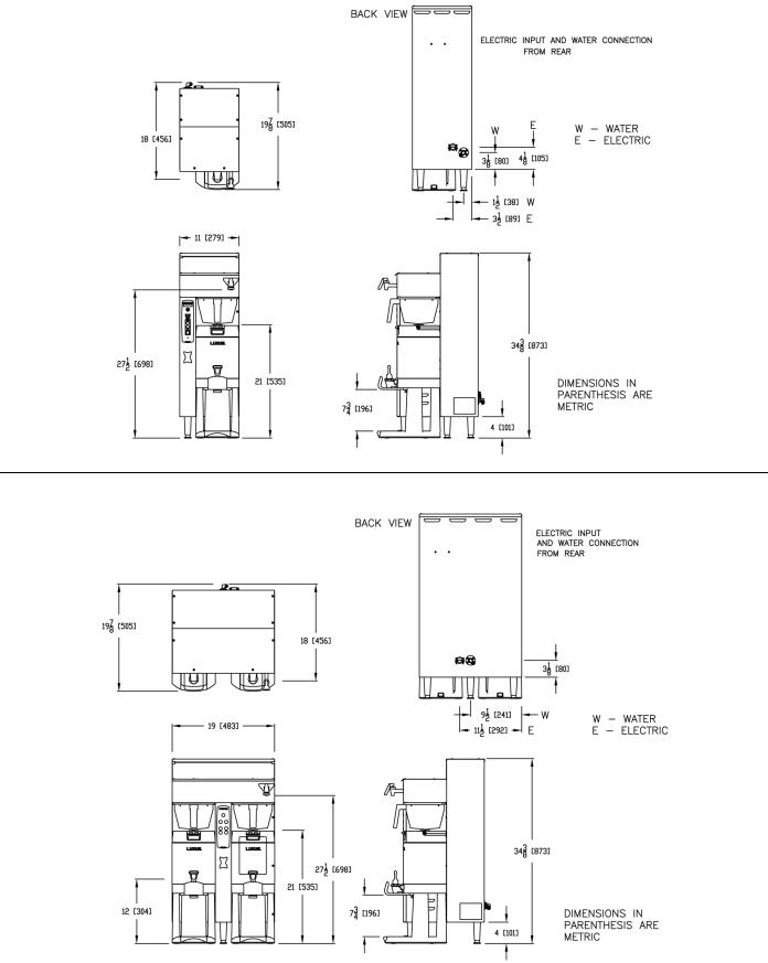
CBS-2041ee
DWG 201143-000
CBS-2042ee
DWG 201144-000
5

Installation
(For Qualified Service Technicians Only)
Keys To A Successful Installation
If not installed correctly by qualified personnel, the brewer will not operate properly and damage may result. Damages resulting from improper installation are not covered by the warranty.
Here are the key points to consider before installation:
Electrical:
All FETCO brewers require NEUTRAL. Ground is not an acceptable substitute. Installation without neutral may cause damage to the electronic components.
The electrical diagram is located on the inside of the lower cover.
The installation must comply with applicable federal, state, and local codes having jurisdiction at your location. Check with your local inspectors to determine what codes will apply.
Plumbing:
This equipment is to be installed to comply with the applicable federal, state, or local plumbing codes. The water line must be flushed thoroughly prior to connecting it to the brewer to prevent debris from contaminating the machine.
Before connecting it to the brewer, verify that the water line pressure is 20 – 75 psig and the flow rate meets the following minimum requirements:
CBS-2031ee: |
½ gpm |
CBS-2041ee: 1 |
gpm |
CBS-2032ee: |
1 gpm |
CBS-2042ee: 1 ½ gpm |
|
General:
Utilize only qualified beverage equipment service technicians for installation. A Service Company Directory may be found on our web site, http://www.fetco.com.
Installation Instructions
Brewer Setup
1. Review the Dimensions for the unit you are installing. Verify that the brewer will fit in the space intended for it, and that the counter or table will support the total weight of the brewer and dispensers when filled.
2. The brewer’s legs are shipped inside the brew baskets. Remove the brew basket(s) and the coffee dispenser(s). Place the brewer on its back and screw in the legs.
3. Place the brewer on the counter or stand.
4. When the brewer is in position, level it front to back as well as side to side by adjusting the legs.
5.Remove the lower cover to access the water and electrical connections. Knock-outs are provided in the back and base of the brewer body for the connections.
Water Connection
1.Water inlet is a 3/8 inch male flare fitting.
2.The brewer can be connected to a cold or hot water line. Cold water is preferred for best coffee flavor, but hot water will allow for faster recovery times.
3.Install a water shut off valve near the brewer to facilitate service. If an in-line water filter is used, it should be installed after the water shut off valve and in a position to facilitate filter replacement.
4.Flush the water supply line and filter before connecting it to the brewer.
5.Verify that the water line meets the pressure and flow requirements listed above.
Electrical Connection – US & Canada
1.Verify that the actual voltage at the electrical service connection is compatible with the specifications on the brewer’s serial number label. Make sure the electrical service includes neutral.
2.The temperature and water tank fill level are pre-set at the factory. There is no need to turn off the heaters during the installation process. The heaters are disabled by the control board until the tank is full of water. The heating process will start automatically when the tank has filled.
3.The CBS-2031ee and CBS-2041ee models are factory equipped with a 120 V cord and plug. The CBS2032ee and 2042ee have only a terminal block for connecting the incoming power wires. Consult local codes to determine if a cord and plug can be installed, or if the unit must be hard wired.
6
4. A fused disconnect switch or circuit breaker on the incoming power line must be conveniently located near the brewer, and its location and markings known to the operators.
5. The body of the brewer must be grounded to a suitable building ground. A ground lug is provided in the brewer next to the power terminal block. Use only 10 gauge copper wire for grounding.
6. Electrical connections must be secured in-place within the unit to meet national and local standards.
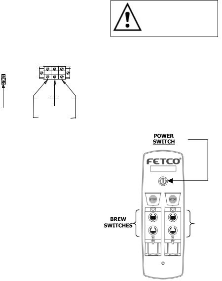
7.Finally, plug the brewer in to the appropriate outlet (120 VAC models), or connect the incoming power wires to the terminal block as shown in accordance with applicable codes (120/208-240 VAC models only).
GROUND LUG
L1 |
N |
L2 |
120V |
120V |
GROUND |
N |
|
|
WIRE |
208-240V |
Final Setup
1.Turn on the incoming water supply line and inspect both inside and outside of the brewer for leaks in all fittings and tubes
2.Turn on the incoming power.
3.Press the brewer’s power switch, which is near the top of the control panel.
4.Within 6 seconds, the hot water tank will begin filling until the water is sensed by the probe at the top of the tank. The display will read “FIL”. The heaters will be disabled by the control board until the tank is full.
5.While the water is heating, the display will read “LO” and the actual water temperature will be displayed. After the water has reached the set temperature, the display will be blank. There is no “ready” light.
6.Review the Operating Instructions. Brew one full batch (water only) on each side to confirm proper fill levels. The brewer is factory set with water only (no coffee) to dispense the correct amount of water. If the actual volume is slightly different from the programmed volume, finetuning the brewer may be necessary. See #60 – 61 in the Advanced Settings & Diagnostics section.
7.Re-attach the covers after one final inspection for leaks. Look closely in the top of the brewer at the dispense fittings during this inspection.
Operator Training
Review the operating procedures with whoever will be using the brewer. Pay particular attention to the following areas:
1.Always pre-heat the dispensers before the first use of each day by filling them half way with hot water, and letting them stand for at least 15 minutes.
2.Don't remove the brew basket until it has stopped dripping.
3.Make sure the dispenser is empty before brewing into it.
4.Show how to attach covers, close, and or secure the thermal dispensers for transporting.
5.Show how to remove and clean the Cascading Spray Domes.
6.Show the location and operation of the water shut off valve as well as the circuit breaker for the brewer.
7.Steam from the tank will form condensation in the vent tubes. This condensation will drip into and then out of the brew baskets. 1/4 cup discharging overnight is possible. Place an appropriate container under each brew basket when not in use.
8.We recommend leaving the power to the brewer on overnight. The water tank is well insulated and will use very little electricity to keep the tank hot. Leaving the brewer in the on position will also avoid delays at the beginning of shifts for the brewer to reach operating temperature.
7
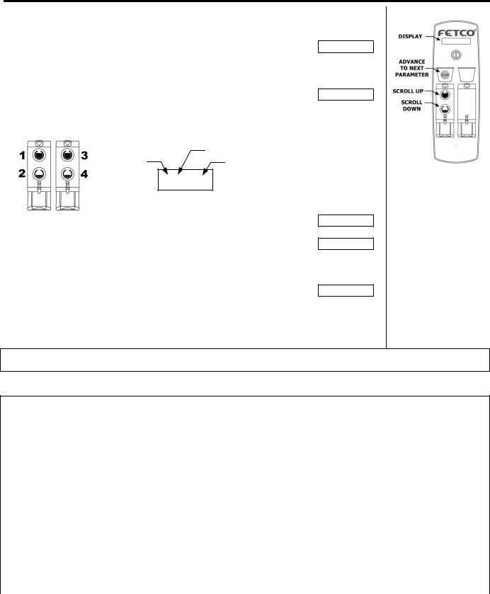
Operating Instructions
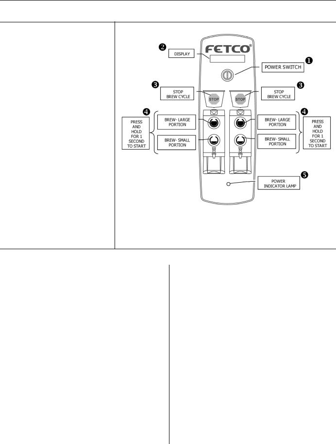
Control Panel Functions
Only switches that are active are illuminated.
Switches that are inactive or disabled are invisible.
XPower Switch
Turns brewer on and off.
To turn on, press and hold briefly until display reads S t b.
Y Display
”FILL” = Water tank is filling. ”LO XXX” = Unit is heating, not
ready to brew. (XXX = actual temperature.)
Blank = Ready to brew.
Also displays error messages.
Z Stop Switches
Stops brew cycle
Lit = Brew cycle in progress Invisible = Not brewing, or dripping
in progress
[ Brew Switches
Starts brew cycle
Must be held in for 1 second Flashing = Brew cycle in progress Lit = Ready to brew
Invisible – Not ready to brew, or batch disabled
(See Programming Section)
\ Power Indicator Lamp
The lamp is lit whenever the unit is connected to a power source.
Brewing
1.Turn the power switch on.
2.Prepare a brew basket with the correct size filter and appropriate amount of coffee.
3.Slide the brew basket completely into the rails.
4.Place a clean, empty, preheated dispenser under the brew basket.
5.Select a batch from the available choices, and hold the corresponding BREW button in for 1 second to start the brew cycle.
6.The STOP button will illuminate, and the selected BREW button will flash, indicating that brewing is in progress. All other BREW buttons will extinguish.
7.When the brew cycle is finished, the STOP button will extinguish and the BREW button will continue to flash for the amount of time programmed into the drip delay setting. This indicates that coffee may still be dripping from the bottom of the brew basket.
8.Before removing the brew basket or dispenser, visually verify that dripping has stopped.
Notes:
Preheat dispenser by filling at least ½ full with water at brewing temperature. Allow it to sit for at least 15 minutes before draining.
8
Programming
Batch Settings
Turn the brewer off by pressing the power switch.
Press and hold the power switch until the display reads P r G. The left side STOP button will illuminate.
Quickly press the STOP button.
The display will show the software version. Example:
Press STOP to continue.
Batches are numbered 1 – 2 (single side) or 1 – 4 (dual side)
|
PARAMETER |
BATCH # |
SETTING |
1.1 1.00
Example: Left Side – Large Batch – Volume 1.0 Gal.
Display
P r G
0.0 03.L
Next, the first batch parameter is displayed – batch 1, brew volume Use the SCROLL UP and SCROLL DOWN buttons to adjust. Press the STOP button to go to the next parameter – brew time.
Continue this way until all parameters are programmed for batch #1. (See the chart below for an explanation of each parameter.)
Next, batch #2 programming begins.
Batches 2 and 4 may be disabled by leaving them set to “OFF”. Change to “ON” to enable. Batches 1 and 3 cannot be disabled.
1.11.00
1.24.00
2.0OFF
After all batches are programmed, go to temperature settings. |
7 200 |
(See next page)
Important! After programming, you must press and hold the STOP button until the display reads STO to save the settings and exit programming mode, or changes will be lost. You may exit programming at any time.
Batch Parameters
X=Batch Number (1 - 4)
Parameter |
Name |
Range |
Increment |
Default Setting |
Comment |
X.0 |
Batch Enabled or |
On/Off |
|
Batch 1 & 3 = ON |
Batch 1 & 3 cannot |
|
Disabled |
|
|
Batch 2 & 4 = OFF |
be disabled. |
X.1 |
Brew Volume: |
|
|
|
To change setting to |
|
|
|
liters or gallons, see |
||
|
|
|
|
|
|
|
CBS-2031ee/2032ee |
0.94 – 4.72 |
0.01 |
2.49 liters |
# 59 in Advanced |
|
CBS-2041ee/2042ee |
0.25 – 1.25 |
0.01 |
1.0 gallons |
Settings section. |
X.2 |
Brew Time (Min:Sec) |
2:00 – 9:30 |
0:30 |
4:00 minutes |
|
X.4 |
Prewet Percent |
0.00 – 15.0% |
1% |
0 % |
Percentage of total |
|
|
|
|
|
brew volume |
X.5 |
Prewet Delay |
0:10 – 5:00 |
0:10 |
1:00 minute |
The time between |
|
(Min:Sec) |
|
|
|
prewetting and start |
|
|
|
|
|
of brew cycle. |
X.6 |
Drip Delay (Min:Sec) |
|
|
|
The time between |
|
|
|
|
|
end of brew cycle |
|
CBS-2031ee/2032ee |
0:30 – 6:00 |
0:10 |
1:00 minute |
|
|
and unlocking of |
||||
|
|
|
|
|
|
|
CBS-2041ee/2042ee |
0:30 – 6:00 |
0:10 |
1:30 minute |
|
|
brew basket. |
||||
|
|
|
|
|
|
|
|
|
9 |
|
|
 Loading...