

Page 1

ALTERNATE
CURRENT
CALL SYSTEMS
TECHNICAL
MANUAL
2004
Page 2
INTRODUCTION
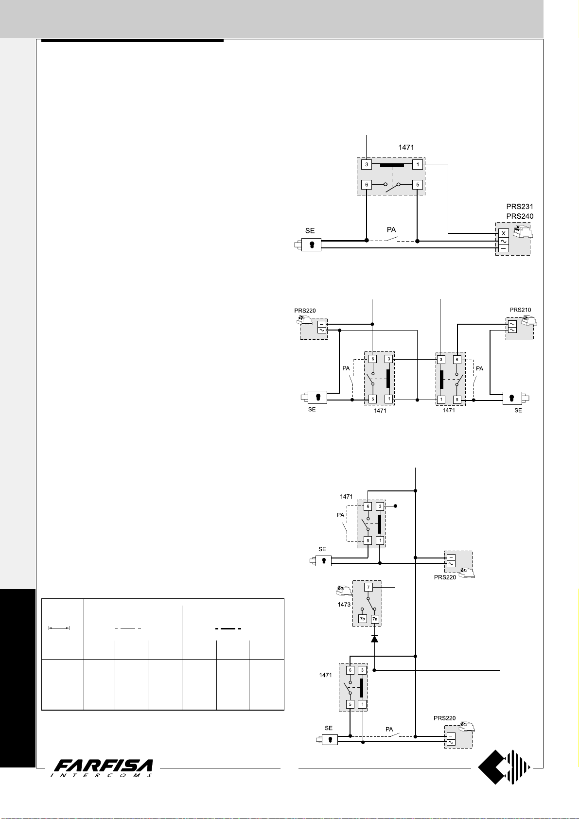
Notice to the installer and user
This edition contains helpful information on the operation and installation of Farfisa video intercoms systems.
In order to make the systems work properly it is necessary to install only
Farfisa equipment, keeping strictly to the items referred to in each
diagram.
Read all the notes carefully, (even the small ones) in each installation
scheme and the working instructions of the system given in the
following pages.
For the sake of clarity, please notice that the sequence of the terminals
of each article has not been followed. Only the terminal code (letter and/
or number) is valid not the graphic sequence.
The items may have more terminals than the ones in the installation
diagrams. The excess terminals must not be used.
Check the integrity of the product after removing it from the packing.
Packing materials (such as plastic bags, cardboard, polystyrene
foam, etc.) must be kept out of the reach of children.
The manufacturer cannot be held responsible for possible damages
caused by improper, erroneous and unreasonable use.
The cable runs of any intercom and video-intercom system must be
kept separate from the mains or any other electrical installation as
required by International Safety Standards.
WARNINGS
An all-pole mains switch with a contact separation of at least
3mm in each pole shall be incorporated in the electrical installation of the building.
Before connecting the unit, make sure its data correspond to
those of the mains.
The apparatus shall not be exposed to dripping or splashing.
For correct operation make sure that ventilation or heat dissipation openings are not obstructed.
Do not open or tamper with power supply or video intercom
apparatus when they are ON. There is high voltage inside.
European Mark of conformity to the EEC
Directives.
CE MARK
The CE mark ensures that the product complies with the requirements of the
European Community Directives in force; in particular, Electrical Safety LVD73/23,
Electromagnetic Compatibility EMC89/336 and Telecommunication Terminals
R&TTE99/5 Directives.
As set forth by the Directives, the technical documentation and Conformity Declarations are available in the Company’s offices for verifications and controls by
competent Authorities.
Avoid bumping and hitting the video intercom apparatus, it
could break of the CRT with consequent projections of fragmented glass.
For installation or maintenance refer only to qualified personnel.
Mark of VDE a German Testing and Certification Institute.
R
T
E
I
C
F
I
C
M
A
E
T
T
I
S
O
Y
N
S
I
S
O
9
0
0
1
:
2
0
0
SGS
0
Quality assured firm.
Italian Association of Electrotechnical and
Electronic Industries
Page 3

12
TECHNICAL MANUAL
2004 edition
INDEX
Installation instructions
Intercoms
- Internal stations
- External door stations
- Power supplies
- Service modules
- Installation instructions
- Installation diagrams
Video Intercoms
- Internal stations
- External door stations
- Power supplies, control units and service modules
- Installation instructions
- Installation diagrams
Telecommunication
- Internal stations
- Intercom-telephone interface
- Electronic PABX
- Installation instructions
- Installation diagrams
Page
2
3
4
7
24
25
26
29
71
72
81
90
91
95
149
150
162
164
170
173
Product List
192
1
(MT12 - Gb2004)
Page 4
INSTALLATION INSTRUCTIONS
I
NTERCOMS *
The Farfisa alternate call system allows for the
realisation of intercom, video intercom, digital
and intercom-telephone systems.
The modularity of Farfisa indoor and outdoor
devices allows for system extension to satisfy
the most diverse user’s requirements, from
individual houses to apartment buildings, from
V
simple intercoms to complete video intercom-
IDEOINTERCOMS *
telephone sets.
Selecting the system
The Farfisa alternate call system allows for the
realisation of different types of installation.
• Intercom systems
• Video intercom systems
• Intercom-telephone systems
• Video intercom systems
T
• Mixed systems (intercom/video intercom/
ELECOMMUNICATION
telephone)
Intercom systems
It is the simplest of the installations. It provides
bidirectional audio communication between
intercoms and external door stations with dooropening function. The following variants of the
basic installation are possible:
-intercommunicating service. It allows for
communication between different intercoms
of the same apartment or between different
apartments with private conversation to other
users and to external stations.
-private conversation. By adding a board to
each intercom you can restrict the communication between internal and external user to
the called user. The other users do not hear
the conversation in progress when they lift the
handset.
For the realisation of a basic intercom system
you need 4 common wires + 1 single for each
user.
For the realisation of basic video intercom
systems you need 7 common wires + 1 single
for each user + common coaxial cable.
Intercom-telephone and video intercomtelephone systems
It is a variant of traditional intercom and video
intercom systems in which internal stations use
telephones (with monitors for video intercomtelephone functions) instead of intercoms or
video intercoms. In this case intercom connections are established over an interface board
that provides telephone and intercom communication. The interface can be a stand alone
product (art. FT11D) or an interface board to
be installed inside the FT105P or FT208P
electronic PABX (art. ES60 or ES65).
Internal stations can use:
-a standard telephone in which intercom functions are obtained by dialling specific codes
on the keypad
-an intercom-telephone set (art.ST740) or
video intercom-telephone set (art.ST740 +
ST7100) with telephone functions and specific buttons for the main intercom services.
In intercom-telephone systems the intercommunicating service can be realized by means
of a PABX that allows also for private conversation.
Intercom-telephone systems need 4 common
wires + 1 single for each user (+ 3 common
wires + common coaxial cable or twisted pair in
case of video intercom-telephone systems) for
connections to the riser. Telephone connections are made with a telephone pair.
Mixed systems (intercom/intercom-telephone/video intercom-telephone)
All intercom, intercom-telephone and video
intercom-telephone systems can be combined
according to the user’s requirements.
The following options are possible for internal
stations:
• Studio modular line for intercom-telephone
and video intercom-telephone systems
• Project line for intercom and video intercom
systems
• PuntoVirgola for intercom and video inter-
com systems
• Slim (900) line for intercom systems
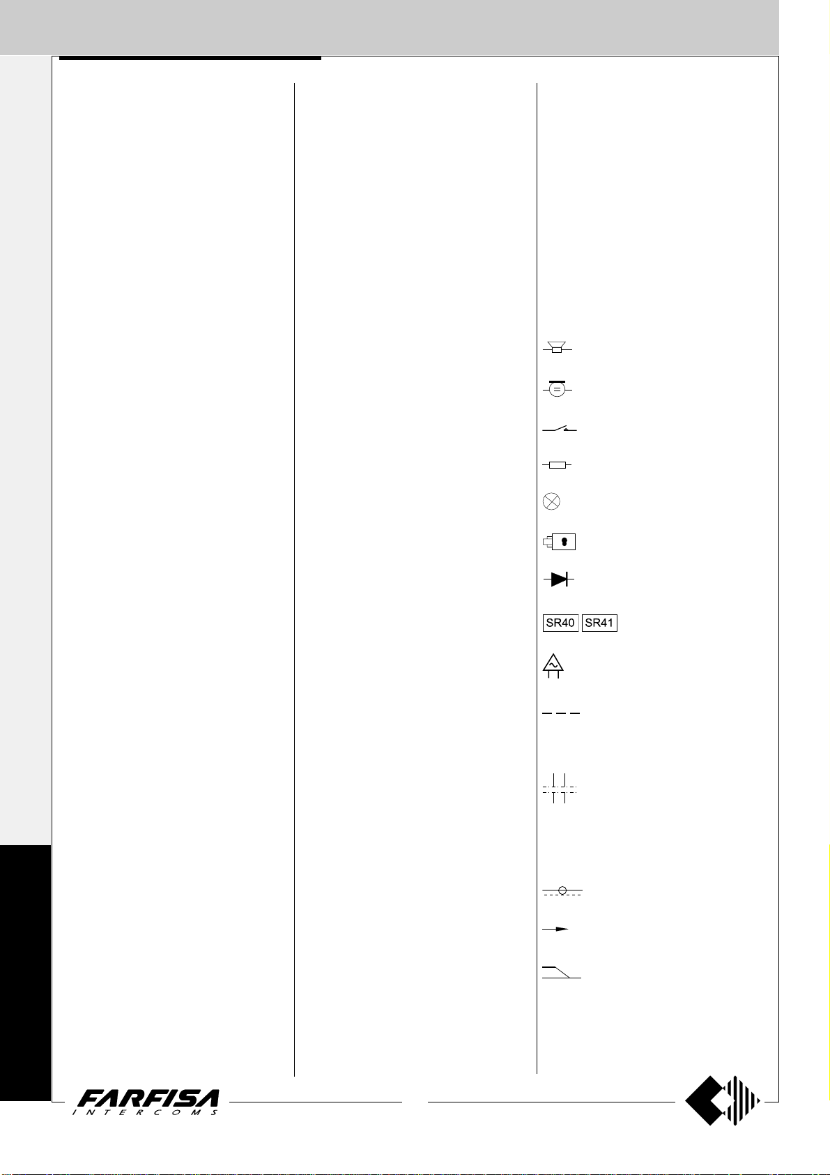
Graphic symbols
The following symbols are used in the installation diagrams:
Speaker
Microphone
Button
Resistance
Lamp
Electric door lock
Diode
Electronic ringer or buzzer
Mechanical buzzer
Video intercom systems
Apart from audio communication and dooropening function, video intercom systems provide visual control of the entrance. The typical
characteristics of video intercom systems are:
- Timed operation. The video intercom of the
called user is enabled for about 40 seconds.
The time doubles if the handset is lifted. The
system returns to the stand-by state when the
handset is replaced.
-Private conversation. Video intercom sys-
tems allow for audio communication only for
the called user. The other users do not hear
the conversation in progress when they lift the
handset.
-Intercommunicating service. This service
allows for audio communication between different intercoms or video intercoms of the
same apartment or between different apartments with private conversation to other users
or external stations.
-Control switching ON. The user can enable
the system, switch ON his/her own video intercom and monitor the area framed by the camera. Additional wires and activation buttons
are needed in case of multiple entrances.
Choosing the correct article
When choosing the article and type of installation, you should consider:
• user’s requirements
• number of users
• installation possibilities
• possible location of articles.
The following options are possible for external
door stations:
• Mody series push-button panels for intercom, telephone and video intercom systems
• Matrix series stainless steel push-button
panels for intercom, telephone and video
intercom systems
• Prestige series brass push-button panels
for intercom, telephone and video intercom
systems
• ErreP/R series push-button panels for intercom and telephone systems
• TM series push-button panels for intercom
and telephone systems
• UP series push-button panels for analogue
intercom and telephone systems with maximum 2 calls
Optional wire (usually control switching ON, door release button or intercommunicating calls)
Dashed line (for schematic purposes
the first and last monitors are shown in
the multi-family systems. Required
additional monitors can be inserted in
such dashed line to complete the installation).
Coaxial cable
xn
Call wires (second and last)
x2
Telephone pair
2
(MT12 - Gb2004)
Page 5

I
NTERCOMS *
Technical manual 12 Edition 2004
INDEX
Internal stations
- Project series intercoms
- PuntoVirgola series intercoms
- Slim (900) series intercoms
External door stations
- Mody series push-button panels
- Matrix series push-button panels
- ErreP/R series push-button panels
- UP series push-button panels
Power supplies
Service modules
Installation instructions
Working instructions
Troubleshooting
Basic installation diagrams
- Si 1 1MO/1 Intercoms connected to 1 external door station
- Si 1 1MO/2 Intercoms with private conversation connected to 1 external door station
- Si 12MO/1 Intercoms connected to 2 automatically switched external door stations
- Si 13MO/1 Intercoms connected to 3 automatically switched external door stations
- Si 16MO/1 Intercom system with secondary door stations and 1 main common station (multiple entrance)
- Si 16MO/2 One-way intercom system with secondary door stations and 1 main common station (multiple entrance)
- Si 17MO/1 Intercom system with secondary door stations and 2 main common stations (multiple entrance)
INTERCOMS
Page
4
4
6
6
7
7
16
22
23
24
25
26
27
28
29
31
33
35
37
39
41
43
V
IDEOINTERCOMS *
T
ELECOMMUNICATION
Intercommunicating installation diagrams
- Si 100L/2 2 intercommunicating intercoms
- Si 100L/1 1 Intercommunicating intercoms (2 to 11 users)
- Si 1 15L/5S 5 intercommunicating intercoms connected to 1 external door station with single calls.
- Si 11 1L/5M 5 intercommunicating intercoms connected to 1 external door station with common call. Electronic bell for internal calls.
- Si 125L/5S 5 intercommunicating intercoms connected to 2 external door stations with single calls. Electronic bell for internal calls.
- Si 121L/5M 5 intercommunicating intercoms connected to 2 external door stations with common call. Electronic bell for internal
calls.
- Si 135L/5S 5 intercommunicating intercoms connected to 3 external door stations with single calls. Electronic bell for internal calls.
- Si 131L/5M 5 intercommunicating intercoms connected to 3 external door stations with common call. Electronic bell for internal
calls.
- Si 161L/1S One-way intercommunicating system with secondary door stations and 1 main common station (multiple entrance)
- Si 11MO/3 Multi-way intercom system connected to 1 external door station. With intercommunication service in 1 or more
apartments and private conversation feature with the external door station and the other apartments.
Application diagrams
- multi-way intercommunicating services
- one-way intercommunicating services
- one-way intercommunicating services in apartment building systems
Electronic bell for internal calls.
44
45
45
47
49
51
53
55
57
59
61
62
62
66
68
3
(MT12 - Gb2004)
Page 6
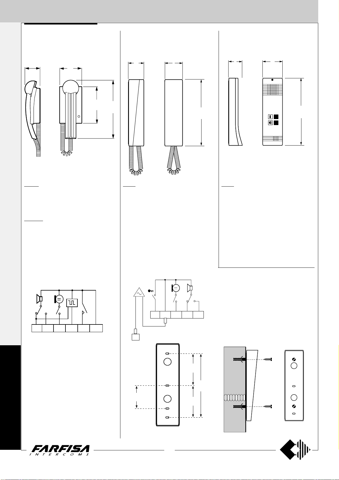
INTERNAL STATIONS
ONOFF
PT515
6
3
L-
L+
I
NTERCOMS *
INTERCOMS PROJECT series
PT502. Led module.
13
"
/
2
16
3
"
/
3
8
V
8672
IDEOINTERCOMS *
T
ELECOMMUNICATION
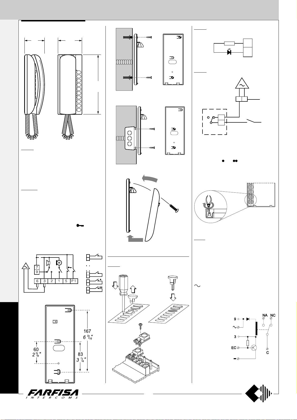
PT520. Two-colour intercom for 4+1 systems
connected to one or more door stations. Complete with buzzer, spiral cord, electronic microphone and two push-buttons that can be increased to 10 by adding the individual pushbutton unit, art.PT501. It can be installed on the
wall with screws or on a back box.
214
1
8
L+
L-
PT515. Bell silencer module (privacy).
"
/
16
Note
We recommend to insert the LED module PT502
and bell silencer module PT515 in the bottom 2
slots marked by and .
To insert them properly it's necessary to remove
the guide of the button sliding from the internal side
of the base cover (see figure).
intercom
call pushbutton
PT520W. Colour: white.
Terminals
1 microphone
2 loudspeaker
3 ground
5 door release push-button (max 1A)
6 buzzer (0.2A)
7 common push-buttons (
9 electronic bell input
P1 service push-button (max 1A)
P2 ÷ P9 service push-buttons (max 0.5A)
W1
P
R
and 1)
RL 36. Relay module. When installed inside
intercoms it allows to activate additional bells
(see page 27). Maximum switching current is
2
P2
1
P7
P8
P9
Fittings for PT520 and PT520W intercoms
PT501. Individual push-button unit.
7
1A (24V).
Terminals
C common terminal of relay
NA normally open contact of relay
NC normally closed contact of relay
- ground
13Vac/dc voltage input
EC relay activation input (ground command)
Wires
9 electronic call input without resistive load
3 ground
O
J
E
C
T
4
(MT12 - Gb2004)
Page 7
INTERNAL STATIONS
INTERCOMS PROJECT series
SR40. Electronic bell module (see inter-
communication diagrams).
Terminals
power supply call input (12Vac-0.5A)
X1 power supply input
(12Vac-0.3A)
X2 call input (ground con-
trol)
SR41. Electronic buzzer module. It can be
used to differentiate calls from external door
stations or external door station and
intercommunicating stations (in this
case it can replace electronic bell
module SR40).
Terminals
4 power supply input (13Vac-70mA;
9÷20Vdc-15mA)
3 ground
SM50. Private conversation module (see
pages 32 and 100).
Terminals
C audio line receiver
B audio line transmitter
- ground
9 7
2315P16
RL36
or
SM50
or
SR40
or
SR41
X2
X1
9
9
10K
C
R1
B
-
+
7
43
2136
SM 50
PT501
PT501
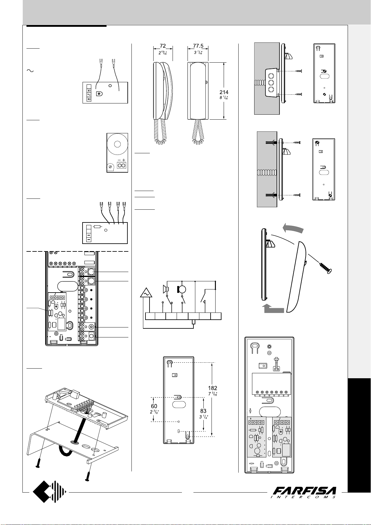
PT510. Two-colour intercom for 4+1 systems
connected to one or more door stations. Complete with push-button, spiral cord, buzzer, electronic microphone. Wall-mounted with screws
or fixed to back box.
PT510N. Colour: beige.
PT510W. Colour: white.
PT524W. White colour finish with carbon mi-
crophone.
Terminals
1 microphone
2 loudspeaker
3 ground
5 door release push-button (max 1A)
6 buzzer (0.2A)
9 electronic bell input
W1
I
NTERCOMS *
V
IDEOINTERCOMS *
T
ELECOMMUNICATION
7
PT502
PT515
PT538. Table adapter for Project series in-
tercoms, with weighted base, junction box and
2.4m connection cable with 13 wires.
91357
2
6
Two of the following
modules can be simultaneously applied
inside the intercoms:
-RL36 relay module;
-SM50 private con-
2916357
X2
C
B
9
2136
X1
9
7
versation module;
-SR40 electronic bell
module;
-SR41 electronic
buzzer module.
P
R
O
J
E
C
T
5
(MT12 - Gb2004)
Page 8
INTERNAL STATIONS
I
NTERCOMS *
INTERCOMS PuntoVirgola series
INTERCOMS 900 series (Slim) OPEN VOICE 900 series
53
V
32
78
11
""
//
1616
IDEOINTERCOMS *
T
ELECOMMUNICATION
PV100. Two-colour intercom for 4+1 systems
connected to one or more door stations. Complete with a push-button, spiral cord, built-in
electronic bell, electronic microphone. Wallmounted with screws or fixed to back box.
PV100W. Colour: white.
Terminals
1 Microphone
2 Loudspeaker
3 Ground
5 Door release push-button (1A max)
6 Buzzer (0.35A)
9 Electronic bell input
128
1
5
46
13
"
/
16
1
910W. Open-voice, white, two-way model for
4+1 systems connected to one or more door
stations, with internal amplification and modulated electronic bell and knob for adjusting the
volume (receiving channel). This model is pro-
2
60
3
"
/
8
225
7
"
/
8
8
48
7
"
/
1
8
205
"
/
1
16
"
/
8
16
924W. Beige intercom for 4+1 systems connected to 1 or more door stations. Complete
with a push-button, spiral cord, electronic microphone, buzzer.
It can be installed on the wall with screws.
66
2
5
"
/
8
225
7
"
/
8
8
vided with two push-buttons (one for connect-
Terminals
1 Microphone
2 Loudspeaker
3 Ground
5 Door release push-button (1A max)
6 Buzzer (0.2A)
9 Electronic bell input (from PRS240 or digital
systems)
ing the audio line and the other one for the
electric door lock). To optimise speech quality
the use of 337C electric speaker is recommended. It can be installed on the wall with
screws or on a wall box.
Terminals
The same of 924 series.
P
V
9
0
0
921653
2
60
1
3
5
2
9
6
83
1
"
/
3
4
166
9
"
/
6
16
3
"
/
8
83
1
"
/
3
4
6
(MT12 - Gb2004)
Page 9
EXTERNAL DOOR ST ATIONS
PUSH-BUTTONS MODY series
I
NTERCOMS *
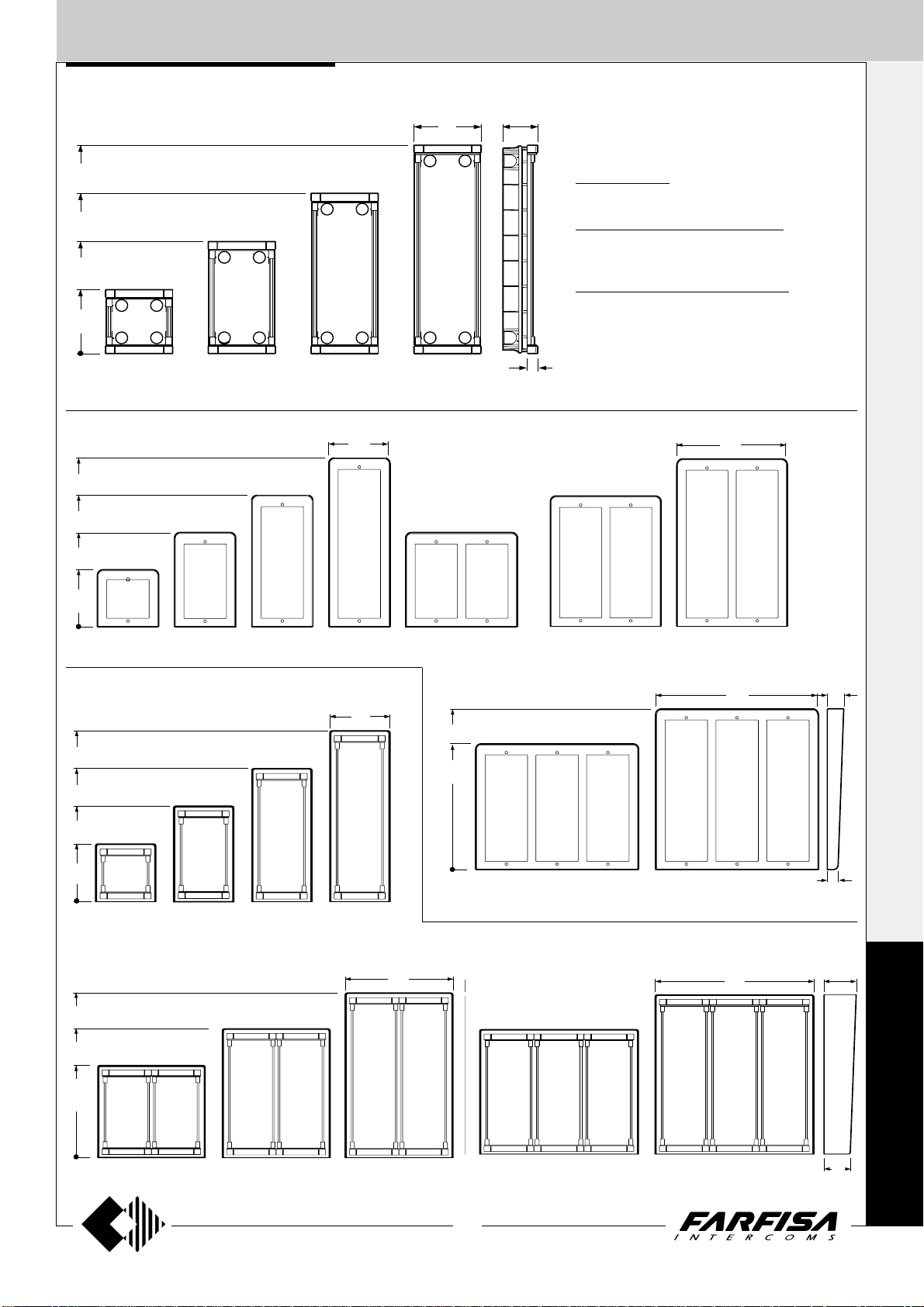
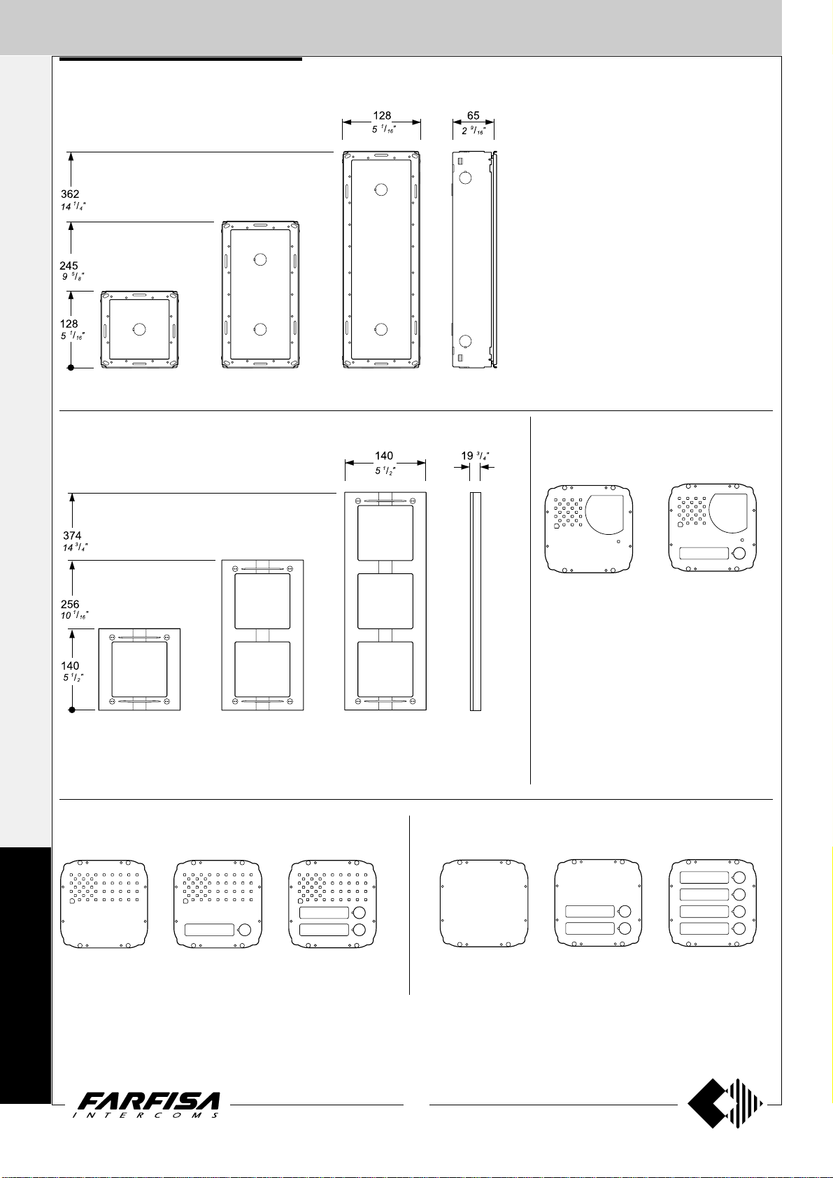
Module frames complete with back box
395
9
"
/
15
16
304.5
"
12
213
3
"
/
8
8
121.5
13
"
/
4
16
MD 71 MD 72 MD 73
Hood covers
5
"
/
16
414.5
323
231.5
16
11
"
/
12
16
1
"
/
9
8
151
5
124
4
7
"
/
8
64
1
"
/
2
2
Push-button panels in extruded aluminium made up
of modular elements. Suitable for the most diverse
installation requirements.
MD71. 72. 73. 74. Plastic back boxes complete with
module frames.
MD81.82.83.804.84.86.808.89.812. Aluminium
V
IDEOINTERCOMS *
hood covers. To be added to MD71.72.73.74 back
boxes.
MD91.92.93.904.94.96.908.99.912. Anodized
aluminium rain shelters with module frames. Used
for wall mounting.
19
3
"
/
MD 74
4
T
ELECOMMUNICATION
15
"
/
16
10
276
7
"
/
8
140
1
"
/
5
2
MD 81 MD 83
Rain shelters with module frames
5
"
/
16
414.5
16
11
"
/
12
323
16
1
"
/
9
8
231.5
140
1
"
/
5
2
5
"
/
414.5
16
16
11
"
/
12
323
16
231.5
1
"
/
9
8
MD 804MD 82 MD 86 MD 808MD 84
151
15
"
/
5
16
414.5
323
11
12
"
/
16
MD 904MD 93MD 92MD 91
276
7
"
/
10
8
401
13
"
/
15
16
5
"
/
16
16
MD 812MD 89
401
13
"
/
15
16
40
9
"
/
1
16
25
"
1
80
1
"
/
3
8
M
O
D
Y
MD 94 MD 96 MD 908 MD 99 MD 912
7
(MT12 - Gb2004)
65
9
"
/
2
16
Page 10
EXTERNAL DOOR ST ATIONS
I
NTERCOMS *
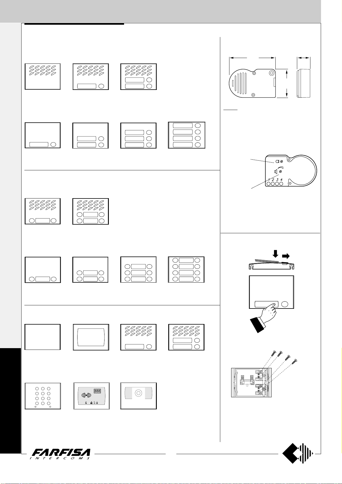
PUSH-BUTTONS MODY series
1 row push-button modules
Modules for electric door speaker (amplifier)
V
IDEOINTERCOMS *
MD 10
without call buttons
Button modules
MD 11
1 call button
T
ELECOMMUNICATION
MD 21
1 call button
2 row push-button modules
Modules for electric door speaker (amplifier)
MD 122
2 call buttons
Button modules
MD 22
2 call buttons
MD 124
4 call buttons
MD 12
2 call buttons
MD 23
3 call buttons
MD 24
4 call buttons
ELECTRIC DOOR SPEAKER
91
9
"
/
3
16
MD 30.
It consists of a double amplifier (receiver and
transmitter) with adjustable volume of 2 channels. Also fittable to Prestige and ErreP/R
series push-button panels (for ErreP/R door
stations by means of 299/1 adapter).
Transmitting volume
adjustment
Receiving volume adjustment
Terminals
1 audio receiver
2 audio transmitter
3 positive power supply 6 ÷ 8Vdc - 60mA
4 ground
Dismounting and protection of name labels
25.5
"
1
55
3
"
/
2
16
MD 222
2 call buttons
MD 224
4 call buttons
MD 226
6 call buttons
Modules: blank, number, access control and cameras
50
MD20
blank module
M
O
D
Y
FC52P. Keypad
module for access
control (see page 9).
2
3
1
5
6
4
8
9
7
B
A
0
MD50
number module
FP52. Proximity
reader for access control (see page 9).
MD 100
Amplified door station with 1 push-button (see page 9)
MD41. MD41D. Black
and white cameras.
MD41C. Colour cameras
(see characteristics on
page 81).
MD 228
8 call buttons
Dismounting of name holder to insert name
label.
MD 200
Amplified door station with 2 push-buttons (see page 9)
In any button module, in order to avoid the
dismounting of name holder, insert a 3MAx12
screw in the holes shown in the picture for each
name plate to be blocked. Screws are not
supplied by the manufacturer.
8
(MT12 - Gb2004)
Page 11
1 2
EXTERNAL DOOR ST ATIONS
10 9 8 7 6 5 4 3 2 1
PUSH-BUTTONS MODY series
I
NTERCOMS *
AMPLIFIED DOOR STATIONS
124
7
"
/
4
8
90
9
"
/
3
16
MD 100. 1 button module.
Fittable in all intercom, telephone, intercommunicating and video intercom systems.
Complete with electric door speaker amplified
in the two channels, receiving adjustable volume, call button and anodized aluminium front
plate. It can replace the MD11 and MD30 mod-
ule and use all the other accessories of the
Mody series.
MD 200. 2 buttons module.
Terminals
- ground
supply 13Vac - 0.13A
1 audio receiver
2 audio transmitter
C call push-buttons common
call push-buttons
name-plate lamp (24V-70mA)
1
12
52
1
"
/
2
16
19
3
"
/
4
2
3
4
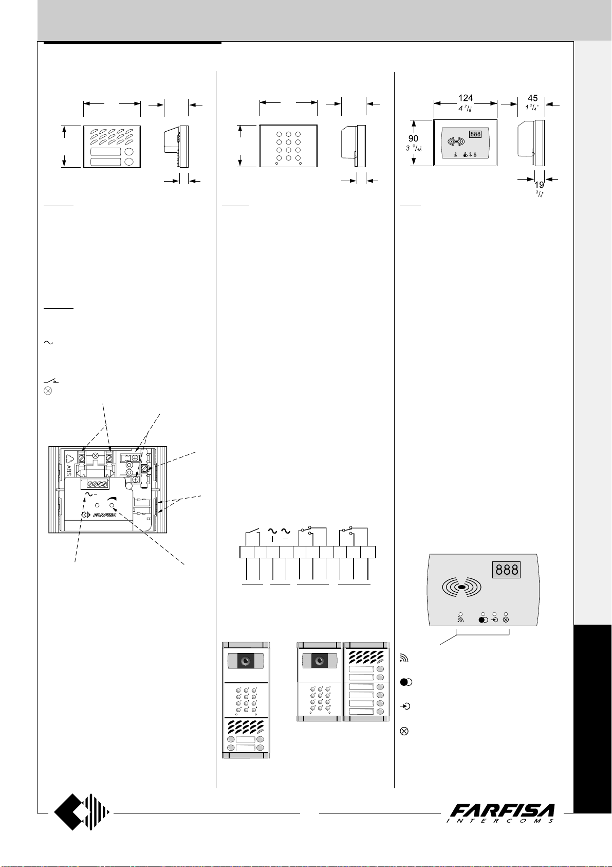
ACCESS CONTROL KEYPAD
124
7
"
/
4
8
1
3
2
4
6
90
9
"
/
3
16
5
7
9
8
0
A
B
FC52P.
Access control keypad with 12 keys and 2
relays for lock release. 4 programmable access codes for each relay. Programmable door
opening time from 1 up 99 sec. for each relay
(or bistable operation of relay 1). Acoustic and
visual confirmation for entered keys, accepted
programming and for wrong codes.
Technical data
Power supply: 12Vac/dc ±10%
Stand-by current: 0.015A
Maximum current consumption: 0.1A
Contact ratings: 12Vac-5A
Numbers of codes for relays 1: 4
Numbers of codes for relays 2: 4 or direct
Activation time for each relay: from 1 to 99sec.
(or bistable relay 1)
Operating temperature: 0° ÷ +40°C
Maximum permissible humidity: 85% RH
Terminals
1 normally closed contact of relays 2
2 normally open contact of relays 2
3 common contact of relays 2
4 normally closed contact of relays 1
5 normally open contact of relays 1
6 common contact of relays 1
7 ground or alternate voltage input
8 positive or alternate voltage input
9-10 connection to optional door lock release
45
3
"
/
1
4
19
3
activation
"
/
4
PROXIMITY READER FOR ACCESS
CONTROL
FP52.
This article allows for the activation of 2 relays
by means of keytags or electronic ISO cards
based on transponder technology.
Programmable activation time from 1 to 63
seconds for every relay. 4 user cards and 1
master card supplied with the product. Acoustic
and visual control signals and 3-digit display to
view numbers and codes during set-up and
operation.
Technical data
Power supply 12Vac/dc ±10%
Stand-by current 0.1A
Maximum current consumption 0.25A
Contact ratings 24Vac - 2A
Max. number of cards 490
Max. number of Master cards 10
Number of relays 2
Relay time 1 to 63 sec.
Minimum recognition distance 3 cm
Maximum recognition time 1 sec.
Operating temperature 0° ÷ +40°C
Maximum permitted humidity 85% RH
Terminals
+/A positive or alternate current input
-/A ground or alternate current input
PB door open button
NC2 normally closed contact of relay 2
NA2 normally open contact of relay 2
C2 common terminal of relay 2
NC1 normally closed contact of relay 1
NA1 normally open contact of relay 1
C1 common terminal of relay 1
V
IDEOINTERCOMS *
T
ELECOMMUNICATION
6
1 Lamp terminals
2 Push-button terminal board
3 Common contact of call push-buttons
4 Terminals on stair light push-button
5 External volume adjustment
6 Terminal board for connection to the system
Installation diagrams
For the installation of the MD100 and MD200
modules see the installation diagrams for systems with one entrance in the “intercom” and
“video intercom” section (for example pages
30, 32, 46, 48, 98, 102, 120, 178 and 180).
5
10987654321
door
release
12Vac
12Vdc
relay 1 relay 2
Example of composition
Card recognition LED. It turns ON during
card recognition.
Relay activation LED. It indicates relay deactivation (red) or activation (green).
Program LED. It turns ON during system
programming.
Card cancellation and system setup LED.
It turns ON during Master or user card cancellation and system setup.
M
O
D
Y
9
(MT12 - Gb2004)
Page 12
EXTERNAL DOOR ST ATIONS
I
NTERCOMS *
PUSH-BUTTONS MODY series
V
IDEOINTERCOMS *
"
5'5
T
ELECOMMUNICATION
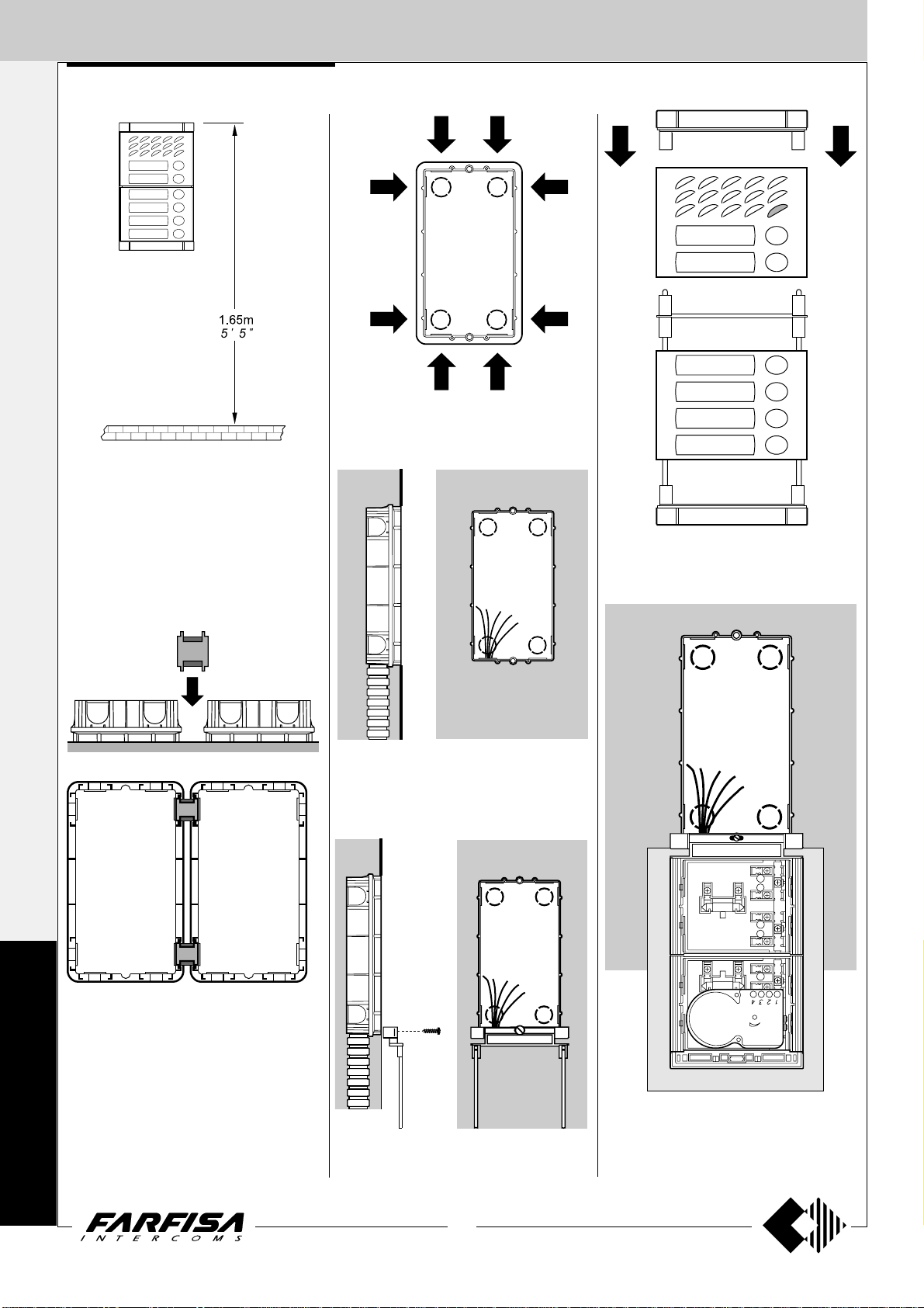
Place the box of the push button panel at a
height of about 1.65m (5' 5") from the floor
keeping the front edges flush-mounted and
vertical to the finished plaster.
Openings for cables.
M
Mounting of button module.
Flush mounting and cables placing.
Insertion of cable bush between back boxes.
O
The cable bushes must be inserted before
brickwork.
D
Y
Lower fixing of the module frame.
10
(MT12 - Gb2004)
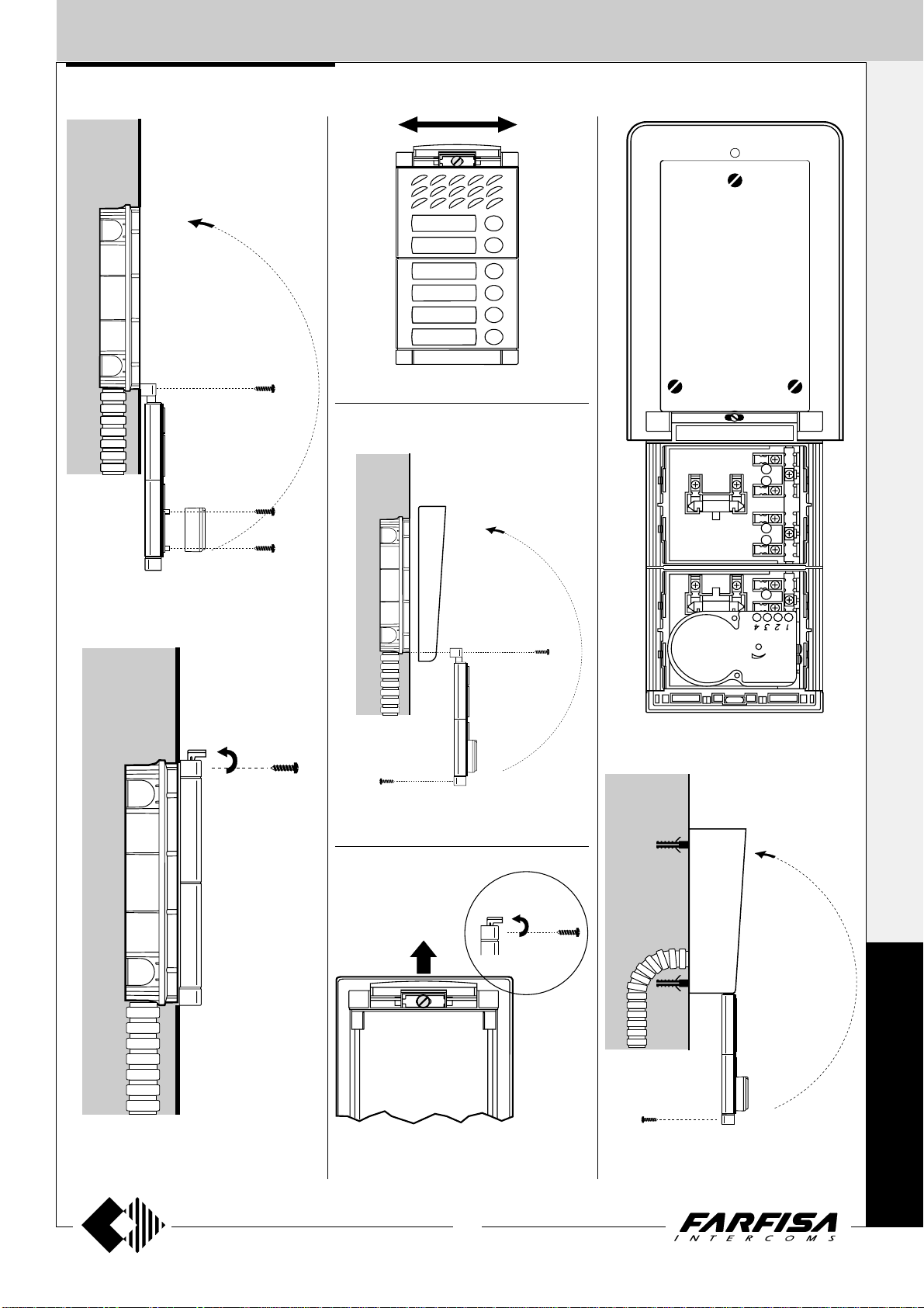
(a)
Lower fixing of the module frame on back box.
It is advised to insert a protection (a) between
panel and wall while fixing.
Page 13
EXTERNAL DOOR ST ATIONS
PUSH-BUTTONS MODY series
I
NTERCOMS *
V
IDEOINTERCOMS *
Mounting of frame bottom and door speaker
(amplifier).
Alignment of the panel.
Hood covers
Fixing of the hood cover between the back box
and the module frame.
T
ELECOMMUNICATION
Modules insertion and wall fixing of rain shelter.
Top fixing of the panel.
Rain shelter
Dismounting of the frame top side from the rain
shelter.
11
(MT12 - Gb2004)
M
O
D
Y
Mounting of the frame top to the rain shelter.
Page 14

EXTERNAL DOOR ST ATIONS
I
NTERCOMS *
PUSH-BUTTONS MODY series
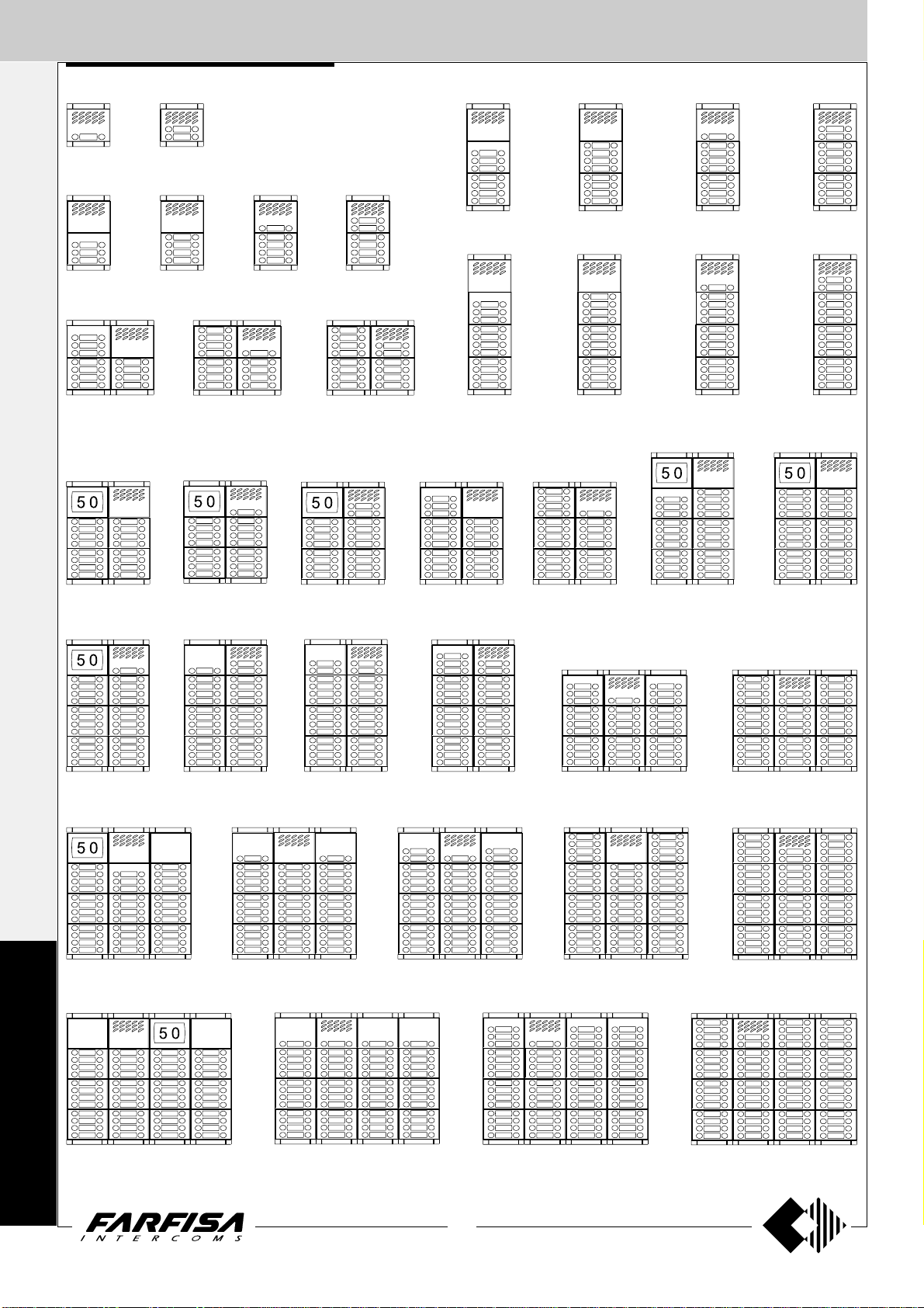
1 call button 2 call buttons
V
IDEOINTERCOMS *
1 row push-button
Example of Mody push-button panel installations.
7 call buttons 8 call buttons
9 call buttons
10 call buttons
T
ELECOMMUNICATION
3 call buttons
11 call buttons
16 call buttons
4 call buttons 5 call buttons 6 call buttons
13 call buttons 14 call buttons
11 call buttons
12 call buttons 13 call buttons
23 call buttons21 call buttons19 call buttons18 call buttons17 call buttons
14 call buttons
24 call buttons
25 call buttons 29 call buttons28 call buttons27 call buttons
35 call buttons 44 call buttons38 call buttons
M
O
D
Y
48 call buttons 62 call buttons
52 call buttons
31 call buttons 34 call buttons
46 call buttons41 call buttons
58 call buttons
12
(MT12 - Gb2004)
Page 15

EXTERNAL DOOR ST ATIONS
PUSH-BUTTONS MODY series
N°
calls
1
2
3
4
5
6
7
8
9
10
11
12
13
14
15
16
17
18
19
20
21
22
23
24
25
26
27
28
29
30
31
32
33
34
35
36
37
38
39
40
41
43
45
46
48
50
52
53
55
58
62
Compositions
and dimensions
124x121.5x19
7
13
/8" x 4
/16" x 3/4")
(4
124x213x19
7
/8" x 8 3/8" x 3/4")
(4
124x304,5x19
(47/8" x 12" x 3/4")
248x213x19
(9 3/4" x 8 3/8" x
248x304.5x19
(9
248x395x19
3
(9
/4" x 15 9/16" x 3/4")
(14
(19 1/2" x 15 9/16" x 3/4")
3
/4" x 12" x
372x304.5x19
372x395x19
5
/8" x 15 9/16" x
496x395x19
3
/4")
(14 5/8" x 12"
x
3
/4")
3
/4")
Door speaker
(amplifier)
1 MD30
1 MD30
1 MD30
1 MD30
1 MD30
1 MD30
1 MD30
1 MD30
1 MD30
1 MD30
1 MD30
1 MD30
1 MD30
3
1 MD30
/4")
1 MD30
1 MD30
1 MD30
1 MD30
1 MD30
1 MD30
1 MD30
1 MD30
1 MD30
1 MD30
1 MD30
1 MD30
1 MD30
1 MD30
1 MD30
1 MD30
1 MD30
1 MD30
1 MD30
1 MD30
1 MD30
1 MD30
1 MD30
1 MD30
1 MD30
1 MD30
1 MD30
1 MD30
1 MD30
1 MD30
1 MD30
1 MD30
1 MD30
1 MD30
1 MD30
1 MD30
1 MD30
or MD74 or MD804 or MD904
Module for
speaker
1 MD11
1 MD12
1 MD10
1 MD10
1 MD11
1 MD12
1 MD10
1 MD10
1 MD11
1 MD12
1 MD10
1 MD10
1 MD11
1 MD12
1 MD10
1 MD10
1 MD11
1 MD12
1 MD10
1 MD10
1 MD11
1 MD12
1 MD10
1 MD10
1 MD11
1 MD12
1 MD12
1 MD12
1 MD12
1 MD12
1 MD11
1 MD10
1 MD11
1 MD12
1 MD10
1 MD12
1 MD11
1 MD10
1 MD11
1 MD12
1 MD11
1 MD12
1 MD12
1 MD12
1 MD10
1 MD10
1 MD11
1 MD12
1 MD11
1 MD10
1 MD12
1 row push-button
Composition board of Mody push-button panels.
Button modules and
number or blank module
-
1 MD23
1 MD24
1 MD24
1 MD24
1 MD24
2 MD24
2 MD24
2 MD24
2 MD24
3 MD24
3 MD24
3 MD24
3 MD24
4 MD24
4 MD24
4 MD24
4 MD24
5 MD24
5 MD24
5 MD24
5 MD24
6 MD24
6 MD24
6 MD24
6 MD24
6 MD24
6 MD24
7 MD24
6 MD24
8 MD24
8 MD24
8 MD24
8 MD24
8 MD24
9 MD24
9 MD24
9 MD24
9 MD24
9 MD24
10 MD24
10 MD24
11 MD24
12 MD24
12 MD24
12 MD24
12 MD24
13 MD24
14 MD24
15 MD24
* or MD20 or MD50 or FC52P or FP52
-
-
-
-
-
-
1 MD23
-
-
-
1 MD23
-
-
-
1 MD23
-
-
-
1 MD23
-
-
-
1 MD23
-
-
1 MD21
1 MD22
1 MD23
2 MD23
-
-
1 MD23
2 MD21
2 MD21
2 MD21
2 MD21
2 MD22
1 MD21
1 MD23
-
2 MD21
3 MD21
3 MD21
2 MD21
1 MD22
-
1*
1*
1*
1*
1*
1*
1*
1*
2*
1*
2*
3*
1*
-
-
-
-
-
-
-
-
-
-
-
-
-
-
-
-
-
-
-
-
-
-
-
-
-
-
-
-
-
-
-
-
-
-
-
-
-
-
Back box and
module frame
1 MD71
1 MD71
1 MD72
1 MD72
1 MD72
1 MD72
1 MD73
1 MD73
1 MD73
1 MD73
2 MD72
2 MD72
2 MD72
2 MD72
2 MD73
2 MD73
2 MD73
2 MD73
2 MD73
2 MD73
2 MD73
2 MD73
2 MD74
2 MD74
2 MD74
2 MD74
2 MD74
2 MD74
2 MD74
2 MD74
3 MD73
3 MD73
3 MD73
3 MD73
3 MD74
3 MD74
3 MD74
3 MD74
3 MD74
3 MD74
3 MD74
3 MD74
3 MD74
3 MD74
4 MD74
4 MD74
4 MD74
4 MD74
4 MD74
4 MD74
4 MD74
Hood
covers
1 MD81
1 MD81
1 MD82
1 MD82
1 MD82
1 MD82
1 MD83
1 MD83
1 MD83
1 MD83
1 MD84
1 MD84
1 MD84
1 MD84
1 MD86
1 MD86
1 MD86
1 MD86
1 MD86
1 MD86
1 MD86
1 MD86
1 MD808
1 MD808
1 MD808
1 MD808
1 MD808
1 MD808
1 MD808
1 MD808
1 MD89
1 MD89
1 MD89
1 MD89
1 MD812
1 MD812
1 MD812
1 MD812
1 MD812
1 MD812
1 MD812
1 MD812
1 MD812
1 MD812
-
-
-
-
-
-
-
Optional
It replaces
MD71, 72, 73, 74
Rain
shelter
1 MD91
1 MD91
1 MD92
1 MD92
1 MD92
1 MD92
1 MD93
1 MD93
1 MD93
1 MD93
1 MD94
1 MD94
1 MD94
1 MD94
1 MD96
1 MD96
1 MD96
1 MD96
1 MD96
1 MD96
1 MD96
1 MD96
1 MD908
1 MD908
1 MD908
1 MD908
1 MD908
1 MD908
1 MD908
1 MD908
1 MD99
1 MD99
1 MD99
1 MD99
1 MD912
1 MD912
1 MD912
1 MD912
1 MD912
1 MD912
1 MD912
1 MD912
1 MD912
1 MD912
-
-
-
-
-
-
-
I
NTERCOMS *
V
IDEOINTERCOMS *
T
ELECOMMUNICATION
M
O
D
Y
13
(MT12 - Gb2004)
Page 16
EXTERNAL DOOR ST ATIONS
I
NTERCOMS *
PUSH-BUTTONS MODY series
2 call buttons 4 call buttons
V
IDEOINTERCOMS *
2 row push-button
Example of Mody push-button panel installations.
14 call buttons 16 call buttons
18 call buttons
20 call buttons
T
ELECOMMUNICATION
6 call buttons
22 call buttons
32 call buttons
8 call buttons 10 call buttons 12 call buttons
26 call buttons 28 call buttons 22 call buttons 28 call buttons
24 call buttons 26 call buttons
46 call buttons42 call buttons38 call buttons36 call buttons34 call buttons
48 call buttons
50 call buttons 58 call buttons56 call buttons54 call buttons
70 call buttons 88 call buttons76 call buttons 92 call buttons82 call buttons
M
O
D
Y
96 call buttons 124 call buttons
104 call buttons
62 call buttons 68 call buttons
116 call buttons
14
(MT12 - Gb2004)
Page 17

EXTERNAL DOOR ST ATIONS
PUSH-BUTTONS MODY series
N°
calls
2
4
6
8
10
12
14
16
18
20
22
24
26
28
30
32
34
36
38
40
42
44
46
48
50
52
54
56
58
60
62
64
66
68
70
72
74
76
78
80
82
86
90
92
96
100
104
106
110
116
124
Compositions
and dimensions
124x121.5x19
(47/8" x 4
124x213x19
7
(4
/8" x 8 3/8" x 3/4")
124x304,5x19
7
(4
/8" x 12" x 3/4")
248x213x19
3
(9
248x304.5x19
3
/4" x 12" x
(9
248x395x19
3
/4" x 15 9/16" x 3/4")
(9
372x395x19
5
(14
/8" x 15 9/16" x
496x395x19
1
(19
/2" x 15 9/16" x 3/4")
13
/16" x 3/4")
/4" x 8 3/8" x
3
/4")
372x304.5x19
(14 5/8" x 12"
3
x
/4")
3
/4")
Door speaker
(amplifier)
1 MD30
1 MD30
1 MD30
1 MD30
1 MD30
1 MD30
1 MD30
1 MD30
1 MD30
1 MD30
1 MD30
1 MD30
1 MD30
3
1 MD30
/4")
1 MD30
1 MD30
1 MD30
1 MD30
1 MD30
1 MD30
1 MD30
1 MD30
1 MD30
1 MD30
1 MD30
1 MD30
1 MD30
1 MD30
1 MD30
1 MD30
1 MD30
1 MD30
1 MD30
1 MD30
1 MD30
1 MD30
1 MD30
1 MD30
1 MD30
1 MD30
1 MD30
1 MD30
1 MD30
1 MD30
1 MD30
1 MD30
1 MD30
1 MD30
1 MD30
1 MD30
1 MD30
or MD74 or MD804 or MD904
Module for
speaker
1 MD122
1 MD124
1 MD10
1 MD10
1 MD122
1 MD124
1 MD10
1 MD10
1 MD122
1 MD124
1 MD10
1 MD10
1 MD122
1 MD124
1 MD10
1 MD10
1 MD122
1 MD124
1 MD10
1 MD10
1 MD122
1 MD124
1 MD10
1 MD10
1 MD122
1 MD124
1 MD124
1 MD124
1 MD124
1 MD124
1 MD122
1 MD10
1 MD122
1 MD124
1 MD10
1 MD124
1 MD122
1 MD10
1 MD122
1 MD124
1 MD122
1 MD124
1 MD124
1 MD124
1 MD10
1 MD10
1 MD122
1 MD124
1 MD122
1 MD122
1 MD124
2 row push-button
Composition board of Mody push-button panels.
Button modules and
number or blank module
-
1 MD226
1 MD228
1 MD228
1 MD228
1 MD228
2 MD228
2 MD228
2 MD228
2 MD228
3 MD228
3 MD228
3 MD228
3 MD228
4 MD228
4 MD228
4 MD228
4 MD228
5 MD228
5 MD228
5 MD228
5 MD228
6 MD228
6 MD228
6 MD228
6 MD228
6 MD228
6 MD228
7 MD228
6 MD228
8 MD228
8 MD228
8 MD228
8 MD228
8 MD228
9 MD228
9 MD228
9 MD228
9 MD228
9 MD228
10 MD228
10 MD228
11 MD228
12 MD228
12 MD228
12 MD228
12 MD228
12 MD228
12 MD228
15 MD228
* or MD20 or MD50 or FC52P or FP52
-
-
-
-
-
-
1 MD226
-
-
-
1 MD226
-
-
-
1 MD226
-
-
-
1 MD226
-
-
-
1 MD226
-
-
1 MD222
1 MD224
1 MD226
2 MD226
-
-
1 MD226
2 MD222
2 MD222
2 MD222
2 MD222
2 MD224
1 MD222
1 MD226
-
2 MD222
3 MD222
3 MD222
3 MD224
3 MD226
-
1*
1*
1*
1*
1*
1*
1*
1*
2*
1*
2*
3*
1*
-
-
-
-
-
-
-
-
-
-
-
-
-
-
-
-
-
-
-
-
-
-
-
-
-
-
-
-
-
-
-
-
-
-
-
-
-
-
Back box and
module frame
1 MD71
1 MD71
1 MD72
1 MD72
1 MD72
1 MD72
1 MD73
1 MD73
1 MD73
1 MD73
2 MD72
2 MD72
2 MD72
2 MD72
2 MD73
2 MD73
2 MD73
2 MD73
2 MD73
2 MD73
2 MD73
2 MD73
2 MD74
2 MD74
2 MD74
2 MD74
2 MD74
2 MD74
2 MD74
2 MD74
3 MD73
3 MD73
3 MD73
3 MD73
3 MD74
3 MD74
3 MD74
3 MD74
3 MD74
3 MD74
3 MD74
3 MD74
3 MD74
3 MD74
4 MD74
4 MD74
4 MD74
4 MD74
4 MD74
4 MD74
4 MD74
Hood
covers
1 MD81
1 MD81
1 MD82
1 MD82
1 MD82
1 MD82
1 MD83
1 MD83
1 MD83
1 MD83
1 MD84
1 MD84
1 MD84
1 MD84
1 MD86
1 MD86
1 MD86
1 MD86
1 MD86
1 MD86
1 MD86
1 MD86
1 MD808
1 MD808
1 MD808
1 MD808
1 MD808
1 MD808
1 MD808
1 MD808
1 MD89
1 MD89
1 MD89
1 MD89
1 MD812
1 MD812
1 MD812
1 MD812
1 MD812
1 MD812
1 MD812
1 MD812
1 MD812
1 MD812
-
-
-
-
-
-
-
Optional
Rain
shelter
1 MD91
1 MD91
1 MD92
1 MD92
1 MD92
1 MD92
1 MD93
1 MD93
1 MD93
1 MD93
1 MD94
1 MD94
1 MD94
1 MD94
1 MD96
1 MD96
1 MD96
1 MD96
1 MD96
1 MD96
1 MD96
1 MD96
1 MD908
1 MD908
1 MD908
1 MD908
1 MD908
1 MD908
1 MD908
1 MD908
1 MD99
1 MD99
1 MD99
1 MD99
1 MD912
1 MD912
1 MD912
1 MD912
1 MD912
1 MD912
1 MD912
1 MD912
1 MD912
1 MD912
-
-
-
-
-
-
-
It replaces
MD71, 72, 73, 74
I
NTERCOMS *
V
IDEOINTERCOMS *
T
ELECOMMUNICATION
M
O
D
Y
15
(MT12 - Gb2004)
Page 18
EXTERNAL DOOR ST ATIONS
I
NTERCOMS *
PUSH-BUTTONS Matrix series
Module frames complete with back box
V
IDEOINTERCOMS *
T
ELECOMMUNICATION
MA 71 MA 72 MA 73
Front frames
Stainless steel anti-vandalism push-button
panels especially studied to withstand burglary,
penetration of solids and water jets (IP 45
protection degree against the penetration of
external solids and water; IK09 against shocks).
The Matrix push-button panels include back
boxes, module frames, die-cast aluminium
decorative frames, button modules, and modules with built-in speaker unit (with or without
camera).
The careful selection of modules allows for
multiple application opportunities; from oneway installations to blocks of flats; from intercom
to video intercom installations.
The push-button elements have been developed
to allow both for horizontal and vertical
configuration.
Video modules with door speaker
integrated
MA 61 MA 63MA 62
Modules with door speaker integrated Push-button modules
M
A
T
MA 10P
without call buttons
R
MA 11P
1 call button
MA 12P
2 call buttons
MA 20
blank module
MA 42
without call buttons
and with B/W camera
MA 42C
without call buttons
and with colour camera
For specifications see page 86.
MA 22
2 call buttons
MA 43
with 1 call button and
B/W camera
MA 43C
with 1 call button and
colour camera
MA 24
4 call buttons
I
X
16
(MT12 - Gb2004)
Page 19
EXTERNAL DOOR ST ATIONS
PUSH-BUTTONS Matrix series
I
NTERCOMS *
Modules with door speaker integrated
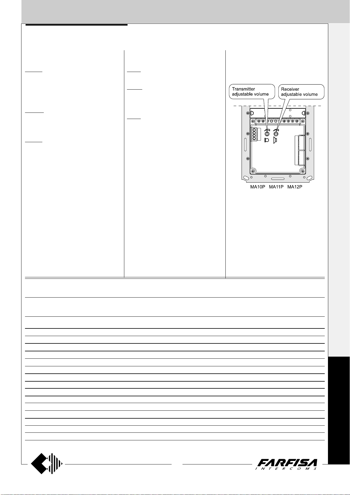
MA 10P.
- amplified speaker unit with volume adjustment of 2 channels (reception and transmission)
-steel front plate
-red operation LED.
MA 11P.
Same as MA 10P, with call button and name
plate panel with breakproof transparent screen
and green LED backlight.
MA 12P.
With 2 call buttons.
Push-button modules
MA 20.
Blank module in stanless steel.
MA 22.
Module with 2 call buttons and name plate
panel with breakproof transparent screen and
green LED backlight.
MA 24.
With 4 call buttons.
Audio adjustments
If necessary, it is possible to adjust the volume
of the 2 channels audio opportunely varying the
external knobs.
V
IDEOINTERCOMS *
T
ELECOMMUNICATION
Technical characteristics of MATRIX modules terminal boards
MA10P MA11P MA12P MA20 MA22 MA24 MA42 MA43
MA42C MA43C
111 11
222 22
333 33
444 44
--------
AAAAAAAA
CC CC C
P1 P1 P1 P1 P1
P2 P2 P2
P3
P4
VV
MM
HH
L- L- L- L- LL+ L+ L+ L+ L+
Reception audio line
Transmission audio line
Power supply input for electric door speaker (6÷12Vdc)
Audio ground
Alternated power supply input or ground for name-plate Led
AC or DC power supply input for name-plate Led (12Vac-dc)
Call push-buttons common
Call push-button
Call push-button
Call push-button
Call push-button
Video signal output (coaxial cable)
Video ground (coaxial shield)
Positive voltage input for camera (18÷24Vdc)
Alternated power supply input or ground for service Led
AC or DC power supply input for service Led (12Vac-dc)
M
A
T
R
I
X
17
(MT12 - Gb2004)
Page 20
EXTERNAL DOOR ST ATIONS
I
NTERCOMS *
PUSH-BUTTONS Matrix series
V
IDEOINTERCOMS *
T
ELECOMMUNICATION
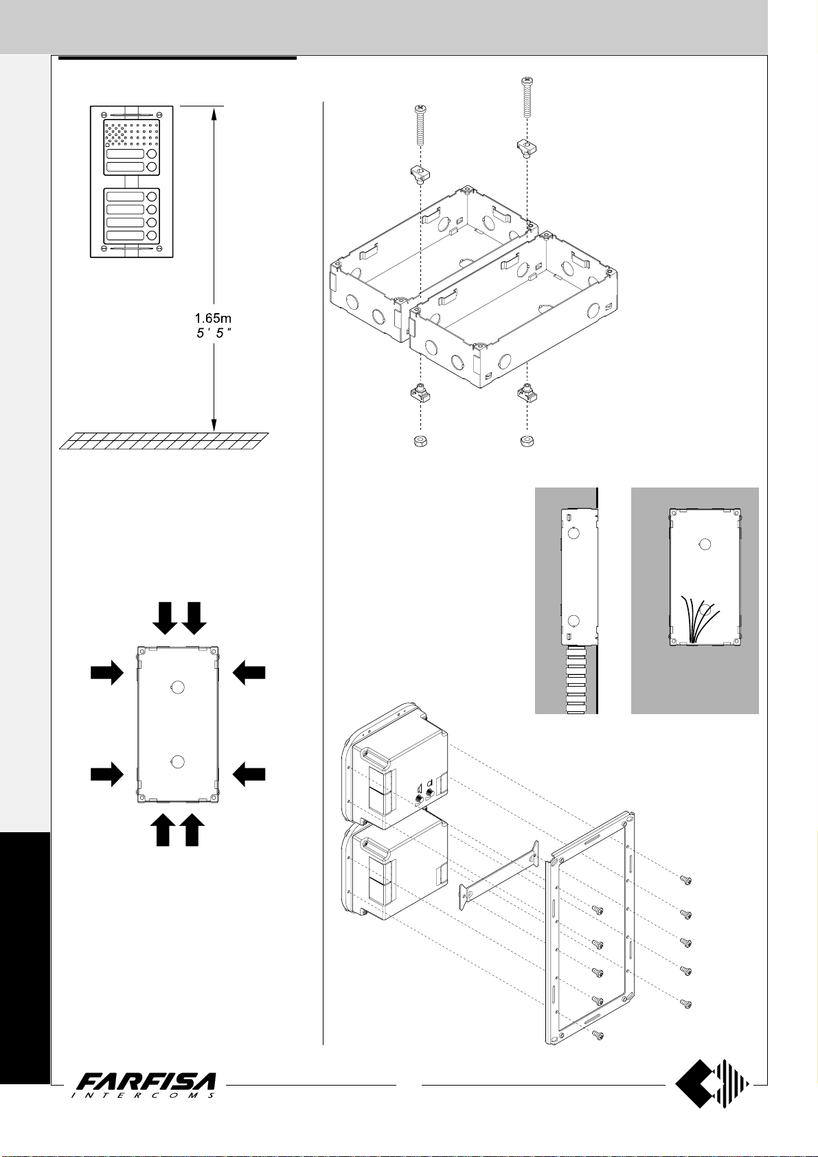
Place the box of the push button panel at a
height of about 1.65m (5' 5") from the floor
keeping the front edges flush-mounted and
vertical to the finished plaster.
Insertion of spacers between back
boxes. Spacers and cable bushing
(not supplied with the products) must
be inserted before brick work.
M
Openings for cables.
A
T
R
I
X
Flush mounting and cables placing.
Mounting modules.
18
(MT12 - Gb2004)
Page 21
EXTERNAL DOOR ST ATIONS
PUSH-BUTTONS Matrix series
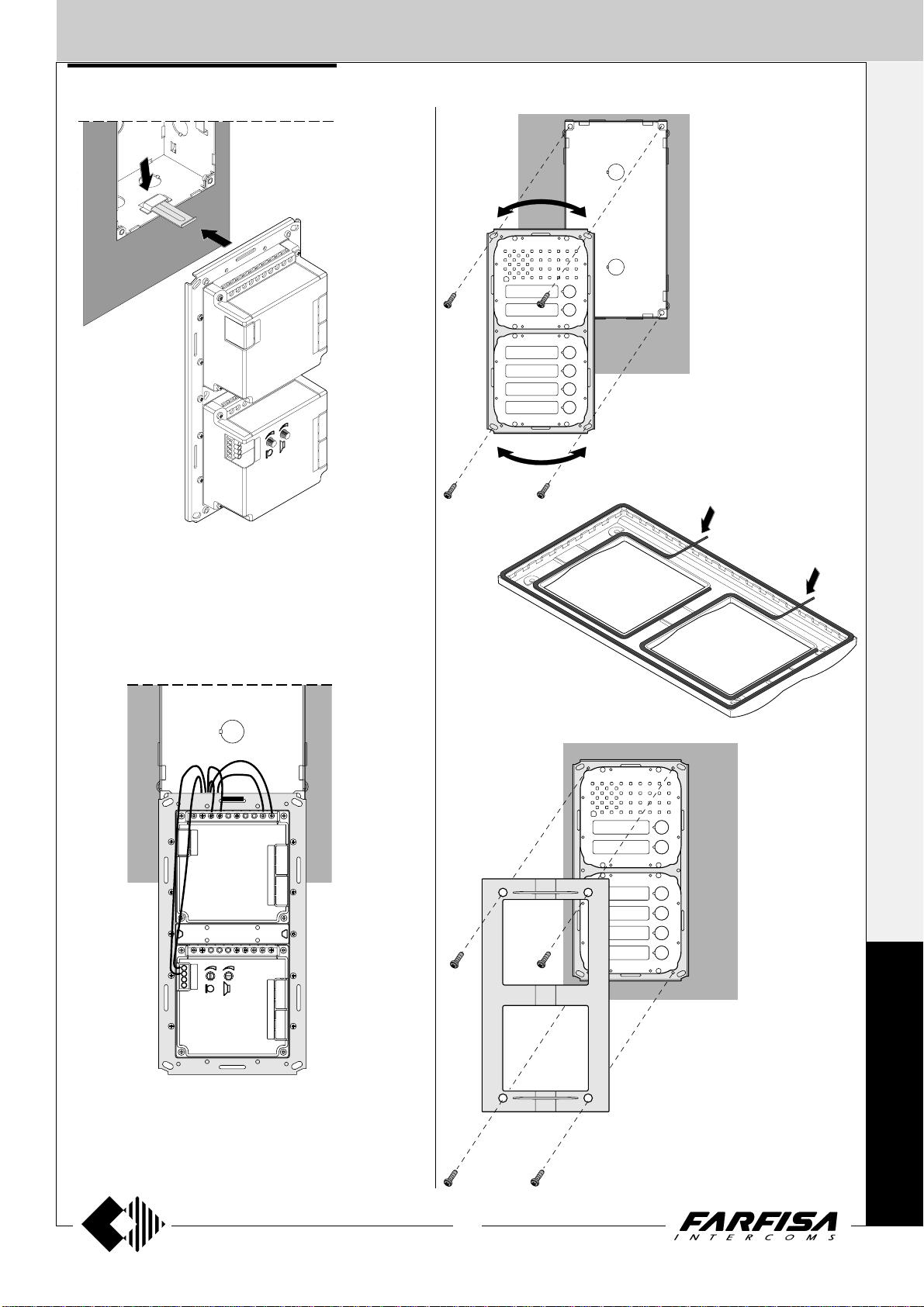
Fixing of frame to back box.
Align the frame before
tightening the screws.
I
NTERCOMS *
V
IDEOINTERCOMS *
T
ELECOMMUNICATION
For easier connection to the electrical system, it is recommended
to insert the metal plate supplied with the product in the back box
opening, as shown in the figure. The plate is used to hook the frame
with pre-assembled modules. Leave the plate in the box to reuse it
for maintenance operations.
Apply the protection gaskets supplied
with the product on the internal part of
the frame openings.
M
Connection of wires to module terminal boxes.
19
(MT12 - Gb2004)
Fixing of frame to module frame.
A
T
R
I
X
Page 22
EXTERNAL DOOR ST ATIONS
I
NTERCOMS *
PUSH-BUTTONS Matrix series
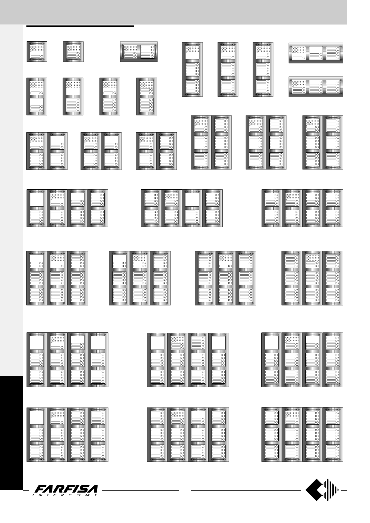
Example of Matrix push-button panel installations.
1 call button 2 call buttons
6 call buttons
V
IDEOINTERCOMS *
3 call buttons
8 call buttons
4 call buttons 5 call buttons 6 call buttons
9 call buttons
10 call buttons
T
ELECOMMUNICATION
11 call buttons
23 call buttons 26 call buttons 30 call buttons
12 call buttons
14 call buttons
15 call buttons 18 call buttons
7 call buttons
10 call buttons
22 call buttons
31 call buttons 32 call buttons 33 call buttons 34 call buttons
M
A
T
R
I
X
20
(MT12 - Gb2004)
40 call buttons38 call buttons35 call buttons
46 call buttons44 call buttons41 call buttons
Page 23

EXTERNAL DOOR ST ATIONS
I
NTERCOMS *
PUSH-BUTTONS Matrix series
N°
calls
1
2
3
4
5
6
7
8
9
10
11
12
13
14
15
16
17
18
19
20
21
22
23
24
25
26
27
28
29
30
31
32
33
34
35
36
37
38
39
40
41
42
43
44
45
46
Compositions
and dimensions
(5
(5
280x256x19
(11" x 10 1/16" x 3/4")
280x374x19
(11" x 14
560x256x19
1
(22
/16" x 10 1/16" x 3/4")
560x374x19
1
(22
/16" x 14 3/4" x 3/4")
140x140x19
1
/2" x 5 1/2" x 3/4")
140x256x19
1
/2" x 10 1/16" x 3/4")
140x374x19
(5 1/2" x 14 3/4" x 3/4")
3
/4" x 3/4")
420x374x19
(16 9/16" x 14 3/4"
x 3/4")
Door speaker
module (amplifier)
1 MA11P
1 MA12P
1 MA11P
1 MA10P
1 MA11P
1 MA12P
1 MA11P
1 MA10P
1 MA11P
1 MA12P
1 MA11P
1 MA12P
1 MA11P
1 MA12P
1 MA11P
1 MA10P
1 MA11P
1 MA10P
1 MA11P
1 MA12P
1 MA11P
1 MA12P
1 MA11P
1 MA10P
1 MA11P
1 MA12P
1 MA11P
1 MA12P
1 MA11P
1 MA12P
1 MA11P
1 MA12P
1 MA11P
1 MA12P
1 MA11P
1 MA10P
1 MA11P
1 MA12P
1 MA11P
1 MA12P
1 MA11P
1 MA12P
1 MA11P
1 MA12P
1 MA11P
1 MA12P
Composition board of Matrix push-button panels.
Front
frames
1 MA61
1 MA61
1 MA62
1 MA62
1 MA62
1 MA62
1 MA63
1 MA63
1 MA63
1 MA63
2 MA62
2 MA62
2 MA62
2 MA62
2 MA63
2 MA63
2 MA63
2 MA63
2 MA63
2 MA63
2 MA63
2 MA63
4 MA62
4 MA62
4 MA62
4 MA62
4 MA62
4 MA62
4 MA62
4 MA62
3 MA63
3 MA63
3 MA63
3 MA63
4 MA63
4 MA63
4 MA63
4 MA63
4 MA63
4 MA63
4 MA63
4 MA63
4 MA63
4 MA63
4 MA63
4 MA63
-
1 MA22
1 MA24
1 MA24
1 MA24
1 MA24
2 MA24
2 MA24
2 MA24
2 MA24
2 MA24
3 MA24
3 MA24
3 MA24
4 MA24
4 MA24
4 MA24
4 MA24
4 MA24
5 MA24
5 MA24
5 MA24
6 MA24
6 MA24
6 MA24
6 MA24
6 MA24
7 MA24
7 MA24
7 MA24
7 MA24
8 MA24
8 MA24
8 MA24
9 MA24
9 MA24
9 MA24
9 MA24
9 MA24
10 MA24
10 MA24
10 MA24
10 MA24
11 MA24
11 MA24
Button modules and
number or blank module
-
-
-
-
-
-
1 MA22
-
-
1 MA22
1 MA22
-
1 MA22
-
1 MA22
1 MA22
1 MA22
-
1 MA22
-
-
1 MA22
1 MA22
-
1 MA22
1 MA22
-
1 MA22
-
-
1 MA22
1 MA22
-
1 MA22
1 MA22
-
-
-
-
-
-
-
-
-
-
-
-
-
-
-
1 MA20
1 MA20
1 MA20
-
-
-
-
1 MA20
1 MA20
1 MA20
1 MA20
-
-
-
-
-
-
-
2 MA20
2 MA20
2 MA20
2 MA20
1 MA20
1 MA20
1 MA20
1 MA20
-
-
-
-
Back box and
module frame
1 MA71
1 MA71
1 MA72
1 MA72
1 MA72
1 MA72
1 MA73
1 MA73
1 MA73
1 MA73
2 MA72
2 MA72
2 MA72
2 MA72
2 MA73
2 MA73
2 MA73
2 MA73
2 MA73
2 MA73
2 MA73
2 MA73
4 MA72
4 MA72
4 MA72
4 MA72
4 MA72
4 MA72
4 MA72
4 MA72
3 MA73
3 MA73
3 MA73
3 MA73
4 MA73
4 MA73
4 MA73
4 MA73
4 MA73
4 MA73
4 MA73
4 MA73
4 MA73
4 MA73
4 MA73
4 MA73
V
IDEOINTERCOMS *
T
ELECOMMUNICATION
M
A
T
R
I
21
(MT12 - Gb2004)
X
Page 24
L
EXTERNAL DOOR ST ATIONS
INTERCOMS * VIDEOINTERCOMS * TELECOMMUNICATION
PUSH-BUTTONS ErreP/R series
RP12
R14 R12
9
"
/
1
40mm
16
RP10
RP8
R10 R8
R. Push-button panels
provided only with buttons.
An electric door speaker
cannot be fitted inside. When
such panels are installed together with the previous
ones, a system with over 12
calls is obtained (see table).
RP6
313
282
250
12
11
9
219
5
8
RP4
5
"
/
16
1
"
/
16
13
"
/
16
"
/
8
RP2 RP 1
RP. Push-button panels with anodized aluminium front panel and buttons,
complete with name plate lights and
height adjustable contacts to compensate imperfections of the wall. The electric door speaker can be fitted inside
the push-button panel.
The unit should be flush-mounted
and the microphone should be
firmly attached to the front panel to
avoid feedback and to obtain the
highest audio quality.
ELECTRIC DOOR SPEAKER (amplifier)
337C. It features a double amplifier (receiver
and transmitter); receiver has volume control. It
is applicable inside the RP or TM push-button
panels (or in other push-button panels by means
of the adaptor art.299).
Provided with an electret microphone and tropicalized speaker.
Terminals
1 audio receiver
2 audio transmitter
3 positive power supply 6÷8Vdc -60mA
4 ground
376
313
282
250
14
12
11
9
219
5
8
AMPLIFIED DOOR STATIONS
13
"
/
16
5
"
/
16
1
"
/
16
13
"
/
16
"
/
8
40
9
"
/
1
16
122
4
13
"
/
16
RP100. 1-button amplified door station.
It is complete with an amplifier, in both channels, electric door speaker, volume control of
the receiving channel, front panel in anodized
aluminium, call button, rain shelter and name
plate light.
It can be installed on the wall with expansion
plugs or on a wall box.
RP200. 2-button amplified door station.
Technical data
Power supply: 13Vac
Operating current: 130mA
Terminals
2 audio receiver
1 audio transmitter
C common contact of call push-buttons
P1 call push-button
P2 call push-button
- ground
alternate voltage input 13Vac
164
6
7
"
/
16
E
r
r
e
P/
R
Instructions of the various ErreP/R push-button panel series and their dimensions en mm (and inches)
L and H = Dimensions of the panel l and h = Dimensions of the back-box
L
L
L
L
H
L
H
Series R RP R+RP R+RP+R R+RP+R+R R+R+RP+R+R
L
H
7
112 (4
/16") 224 (8 13/16") 336 (13 1/4") 448 (17 5/8") 560 (22 1/16")
L
R8 RP1 R8+RP1=9 2R8+RP1=17 3R8+RP1=25 4R8+RP1=33
218.5
(8 5/8")
250
13
(9
281.5
1
(11
313
5
(12
H
/16")
/16")
/16")
R8 RP2 R8+RP2=10 2R8+RP2=18 3R8+RP2=26 4R8+RP2=34
R10 RP4 R10+RP4=14 2R10+RP4=24 3R10+RP4=34 4R10+RP4=44
R12 RP6 R12+RP6=18 2R12+RP6=30 3R12+RP6=42 4R12+RP6=54
R14 RP8 R14+RP8=22 2R14+RP8=36 3R14+RP8=50 4R14+RP8=64
1
103 (4
l l
/16") 215 (8 7/16") 327 (12 7/8") 439 (17 5/16") 551 (21 11/16")
206.5
(8 1/8")
238
3
(9
/8")
269.5
5
(10
301
7
(11
/8")
/8")
22
(MT12 - Gb2004)
h
h
Page 25
EXTERNAL DOOR ST ATIONS
PUSH-BUTTONS UP series
INTERCOMS * VIDEOINTERCOMS * TELECOMMUNICATION
Surface mounted version
106
3
4
"
/
16
46
13
"
/
1
16
151
15
"
/
5
16
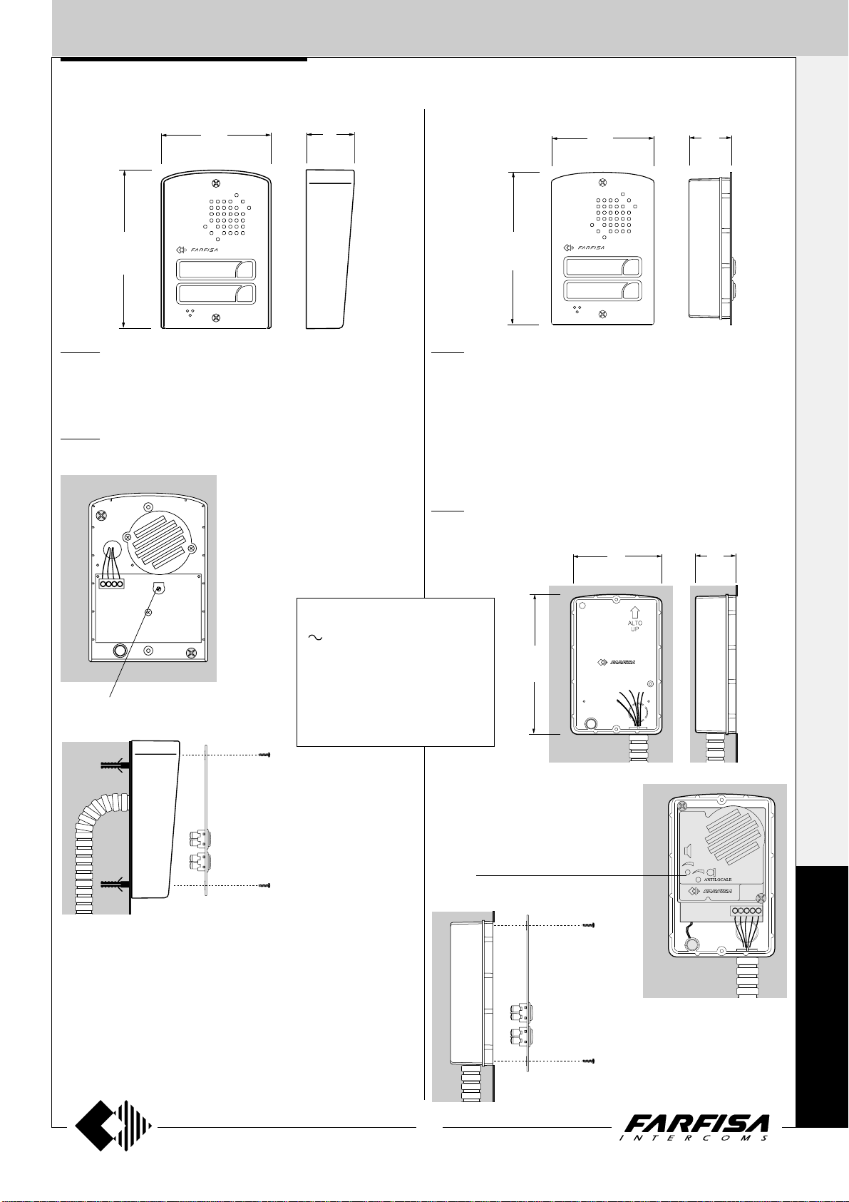
UP 100. Amplified push-button panel with 1 call button.
Fittable in all 4+1 intercom and intercommunicating systems.
Complete with electric door speaker amplified in the two channels,
volume control of the receiving channel, front panel in anodized aluminium with call button. Wall-mountable with expansion plugs.
UP 200. Amplified push-button panel with 2 call buttons.
Flush mounted version
100
15
3
"
/
16
42.5
11
1
"
/
16
148
13
"
/
5
16
UP 11. Amplified push-button panel with 1 call button.
Fittable in all 4+1 intercom and intercommunicating systems.
Complete with electric door speaker amplified in the two channels,
volume control of the receiving channel, front panel in anodized aluminium with call button.
To install it you must:
- fix the back box to the wall;
- install the speaker unit;
- make the connections;
- screw the front panel onto the back box.
UP 12. Amplified push-button panel with 2 call buttons.
External volume adjustment
Terminals
- ground
13Vac-70mA voltage input
1 audio receiver
2 audio transmitter
Wires
C yellow wire connected to call but-
ton common.
138
7
"
/
5
16
External volume adjustment
90
9
"
/
3
16
40
9
"
/
1
16
U
23
(MT12 - Gb2004)
P
Page 26
POWER SUPPLIES
I
NTERCOMS *
The power supply is not provided with fuses,
but it is protected against overloading or shortcircuiting by a heat sensor (thermoprotector),
to restore power, it is necessary to cut off the
mains voltage for about one minute. Reconnect
power after having repaired the fault.
V
Do not obstruct the openings or the ventilation
IDEOINTERCOMS *
or heat ejection slots to allow the equipment to
operate correctly. The power supply can be
installed on DIN rail or screwed to the wall.
All the power supplies described in this manual
replace the corresponding ones with similar
initials. E.g.: PRS220 replaces PRS220D,
PRS220K, etc. PRS226 replaces PRS226D
and PRS226K.
All power supplies can provide power for a
maximum of 6 24V-3W lamps for illuminating
push-button panel name plates. For more than
6 lamps, PRS210 transformer should be
T
installed.
ELECOMMUNICATION
General technical data
Input voltage: 127Vac or 220-230Vac
Working temperature: 0°÷+50°C
Maximum of humidity: 90%RH
Warning
All power supplies in this manual can work
either 127Vac or 220-230Vac.
Check carefully the right connection.
127V
127Vac
220-230Vac
230V
PRS 220. STABILIZED POWER SUPPLY.
It is provided to supply 4+1 intercom systems
(electric door lock, name plate lamps, electric
door-speakers, amplifier, etc.)
Technical data
Power: 15VA
Housing: DIN 4 modules A
Weight: 0.45 Kg. (0.99lb)
Approved by:VDE (according to the Safety
Standard EN60065)
Output terminals
- Ground
+ Audio line power supply 6Vdc-0.1A
Power supply 13Vac for:
- name plate lamps, exchangers
(continuous load 0.6A)
- electric door lock and bells (intermittent load
1A)
PRS226. STABILIZED POWER SUPPLY/
SWITCHER.
It is able to supply intercommunicating intercom
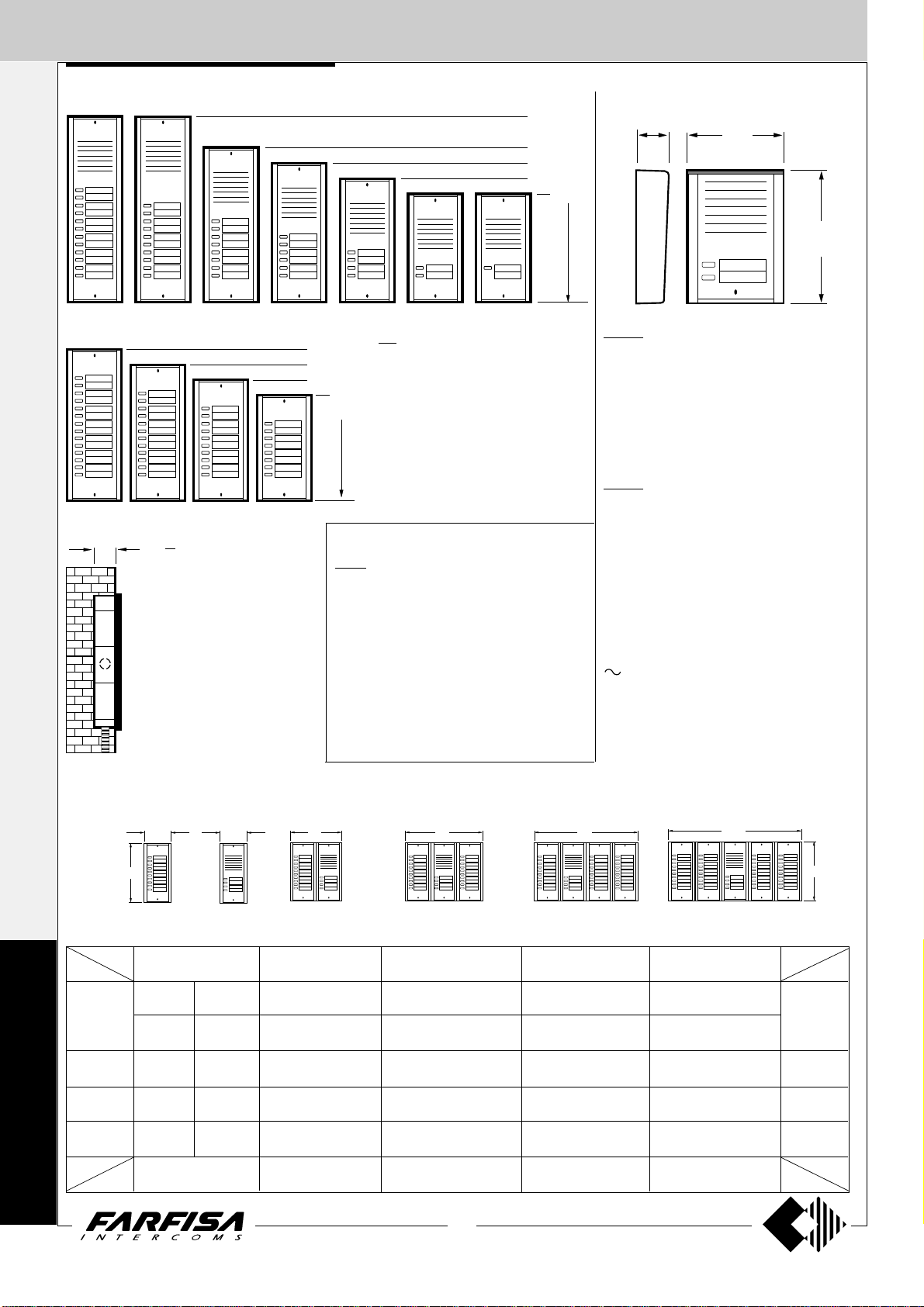
systems and to switch over automatically audio
connection of the door station and of the
intercommunicating service to the intercoms.
Technical data
Power: 18VA
Housing: DIN 6 modules A
Weight: 0.5 Kg. (1.1lb)
Approved by:VDE (according to the Safety
Standard EN60065)
9 Electronic call input for switching over multi-
way installations
4 Relay switching common terminal controlled
from entrance 9
4a NC relay switching controlled from entrance 9
4b NA relay switching controlled from entrance 9
PRS 240. STABILIZED POWER SUPPLY
WITH ELECTRONIC RINGING GENERATOR.
Power supply with modulated electronic ringing generator for calls. It supplies the voltages
needed for the correct operation of intercom
systems.
Technical data
Power: 18VA
Ringing frequency: 450Hz modulated
Housing: DIN 6 modules A
Weight: 0.5 Kg. (1.1lb)
Approved by: VDE according to the Safety
Standard EN60065
Output terminals
- Ground
+ Audio line power supply 7.2Vdc-0.1A
X Power supply for aux. services 12Vdc-0.2A
Power supply 13Vac for:
- name plate lamps (continuous load 0.6A)
- electric door lock and bells (intermittent load
1A)
C+ Modulated electronic call output 12Vpp-0.25A
7 Continuous electronic call output 12Vpp-0.25A
127V
0 230V
127V
0 230V
PRS 210. TRANSFORMER.
Used to power 13Vac devices; MD100, MD200,
RP100, RP200, UP series amplified external
door stations, accessories, additional door
locks, name plate light, etc.
Technical data
Power: 15VA
Output voltage: 13Vac
Maximum load: 0.7A
Maximum of intermittent load: 1A
Housing: DIN 3 modules A
Weight: 0.42 Kg. (0.93lb)
Approved by: VDE according to the Safety
Standard EN60065
Output terminals
- Ground
+ Audio line power supply 8Vdc-0.1A
X Power supply for auxiliary services 12Vdc-
0.2A
Power supply 13Vac for:
- name plate lamps, exchangers (continuous
load 0.6A)
- electric door lock and bells (intermittent load
1A)
7 Power supply 13Vac for electric door lock and
bells (intermittent load 1A)
A Output for call from push-button panel 13Vac-
0.15A
G Audio line receiver from intercoms
2 Audio line transmitter to intercoms
D Audio line transmitter to electric door speaker
C+ Audio line receiver from electric door speaker
PRS226E. STABILIZED POWER SUPPLY/
SWITCHER.
As above, with the following additional terminals and the modification of terminal 7.
7 Electronic bell output for intercommunications
Y Electronic bell output for push-button panel
PRS 235.
POWER SUPPLY FOR SYSTEMS
WITH PRIVATE CONVERSATION MODULE.
It may be installed with Project series intercoms
for supplying power to 4+1 systems with private
conversation module. Only the intercom which
has been called can speak to the door station.
All the other users are isolated.
Technical data
Power: 18VA
Housing: DIN 6 modules A
Weight: 0.5 Kg. (1.1lb)
Approved by: VDE according to the Safety
Output terminals
- Ground
+ Audio line power supply 7.2Vdc-0.1A
X Power supply for auxiliary services 12Vdc-
0.2A
Power supply 13Vac for:
- name plate lamps (continuous load 0.6A)
- electric door lock and bells (intermittent load
1A)
C+ Power supply for bells 13Vac- 0.15A
Standard EN60065
65
9
"
/
2
16
65
9
"
/
2
16
65
2
9
"
/
16
PRS226
PRS226E
54
1
"
/
2
8
89
1
"
/
3
2
PRS210 PRS220
70
3
"
/
2
4
89
1
"
/
3
2
107.5
1
"
/
4
4
89
1
"
/
3
2
PRS235
PRS240
24
(MT12 - Gb2004)
Page 27
SERVICE MODULES
3
"
2
/
1
89
2
"
16
/
9
2
"
4
/
3
70
65
I
NTERCOMS *
74
15
2
140
1
"
/
5
2
89
1
"
/
3
2
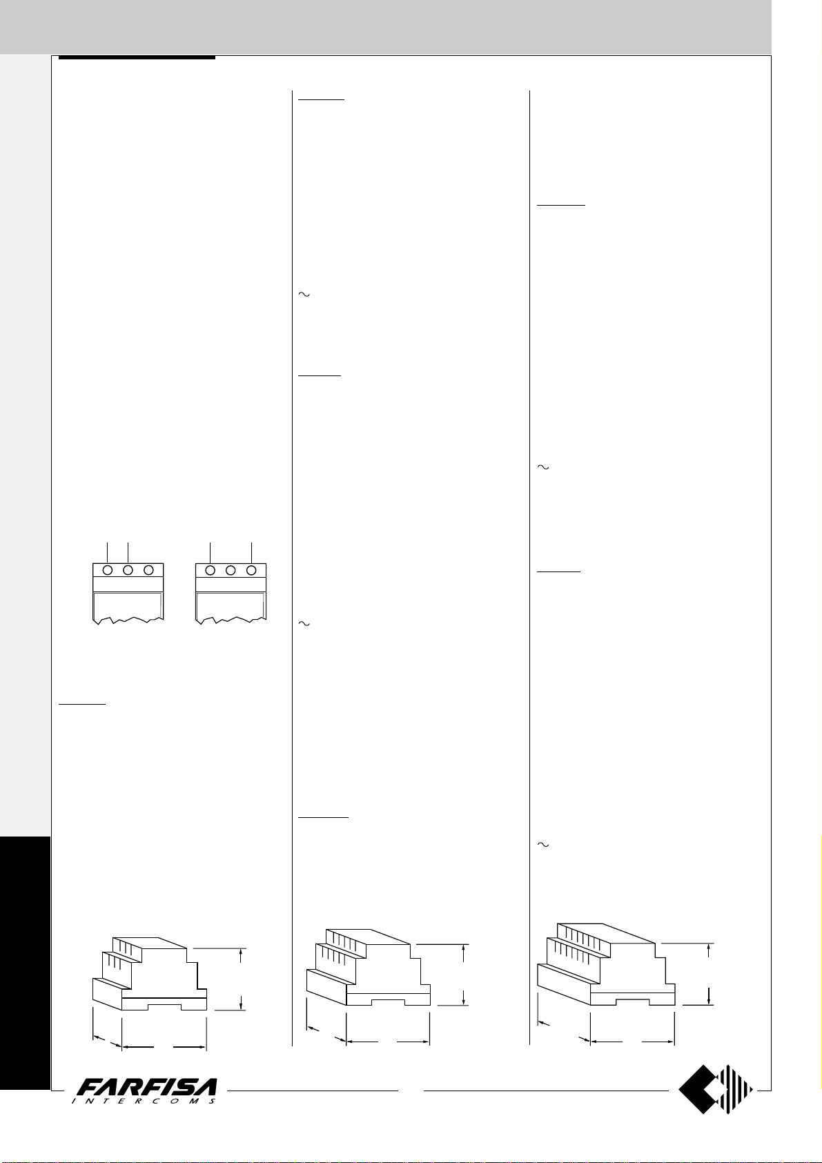
1473. 4-CONTACT ANALOG EXCHANGER.
It is installed in intercom systems with two or
more entrances for switching the audio lines
and door lock of the calling entrance. It can be
installed on DIN bar or with two screws. In
housing DIN bar 8 modules A.
Art. 1473 completely replaces the functions of
models 473 and 273.
Technical data
Power supply: 13Vac; 15÷21Vdc
Current consumption: 0.1A
Number of exchanges: 4
Max. switching current: 5A (50V)
Housing: DIN 8 modules A
Operating temperature: 0° ÷ 50°C
Maximum permissible humidity: 90% RH
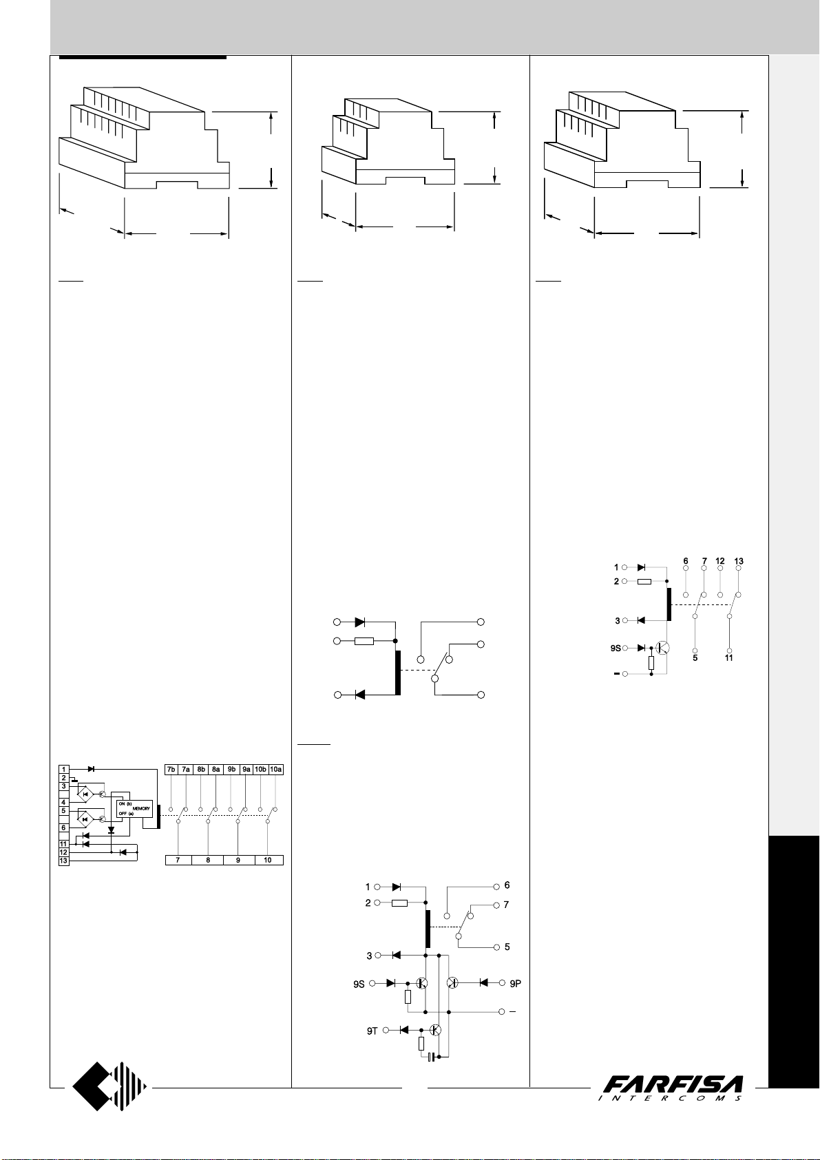
Terminals
1 Power supply 13Vac-0.1A
2 Ground
3 and 4 Driver to switch the relay to “b” posi-
tion - ON position
5 and 6 Driver to switch the relay to “ a” posi-
tion - OFF position
7, 8, 9 and 10 Common contact of relays
7a, 8a, 9a and 10a OFF position of the relay
contacts
7b, 8b, 9b and 10b ON position of the relay
contacts
11 Ground command to switch the relay to “a”
position - OFF position
12 Ground command to switch the relay to “b”
position - ON position
13 Electronic call input from PRS240
"
/
16
54
1
"
/
2
8
3
89
1
"
/
2
1471. RELAY UNIT
A low voltage, low current (DC/AC) unit, it can
switch voltages up to 50V and 5A max. Used
for auxiliary services (e.g. stair lights, call for 4
or more bells, door release etc).
It can be installed on DIN bar or with two screws.
In housing DIN bar 3 modules A.
Technical data
Power supply: 13Vac; 12÷24Vdc
Current consumption: 0.05A
Number of exchanges: 1
Switching current: 5A (50V)
Housing: DIN 3 modules A
Operating temperature: 0° ÷ 50°C
Maximum permissible humidity: 90% RH
Terminals
1 Alternate current input 13Vac-dc
2 Continuous current input 21Vdc
3 Negative half-wave input or ground
5 Common contact of relay
6 Normally open contact of relay
7 Normally closed contact of relay
1
2
3
1471E. RELAY UNIT
2
65
6
7
5
9
"
/
16
V
IDEOINTERCOMS *
1472. 2-CONTACT RELAY UNIT
Same as 1471, but with 2 relays and 9S input
terminal.
Technical data
Power supply: 13Vac; 12÷24Vdc
Curre nt c ons umpt ion : 0.05A
Number of exchanges: 2
Switching current: 1A (24V)
Housing: DIN 4 modules A
Operating temperature: 0° ÷ 50°C
Maximum permissible humidity: 90% RH
Terminals
In addition to terminals of art. 1471 you find:
11 Common contact of relay 2
12 Normally open contact of relay 2
13 Normally closed contact of relay 2
9S Electronic call input with resistive load
- Ground
T
ELECOMMUNICATION
Same as 1471, but with 9S, 9T and 9P input
terminals. In housing DIN bar 4 modules A.
Terminals
In addition to terminals of art. 1471 you find:
9P Electronic call input without resistive load
9S Electronic call input with resistive load
9T Electronic call input timed operation (1 sec.)
- Ground
25
(MT12 - Gb2004)
Page 28
INSTALLATION INSTRUCTIONS
I
NTERCOMS *
General characteristics
- The cable runs of intercom and video intercom installations must be
kept separate from the mains or any other electrical installation as
required by the International Safety Standards and the entire
installation must be realized in compliance with the safety rules in force
V
IDEOINTERCOMS *
in any specific Country.
- It is necessary to provide a disconnecting and safety switch before the
power supply. Use a single general switch in case of several power
supplies (also in multiple entrance).
- Before connecting the power supply make sure that its rating data
corresponds to this of the mains.
- For electromagnetic reasons, all service modules must be installed
near their power supply.
Wires
1) For the correct operation of the intercom system you must choose the
correct type of cable.
2) Wires must be dimensioned according to the distance of the different
T
ELECOMMUNICATION
devices and their current consumption.
3) Do not connect wires in parallel to reach the required cross-section
(for example multi-pair telephone cables). Only use a single wire with
suitable cross-section. When using multi-core cables you must select
them with low parasite parameters (low capacitance per metre, low
inductance over Ohm).
4) If the installation includes additional power supplies you must place
them near the device to be powered.
Background noise
To avoid possible background noise over the speech line, it is advisable:
5) not to lay intercom or telephone cables in the same runaway as the
wires used to power alternate current loads;
6) to avoid using the same multi-core cable to transmit audio signals
and alternate current power supplies (lamps, amplified external door
stations, electrical door locks). Always use separate wires for alternate current power supplies;
7) not to connect name-plate lamps (or other devices powered with
alternate current) to terminal 4 (-) of the speaker unit; 2 wires must
originate from terminal - (minus sign) of the power supply, one for
terminal 4 of the speaker unit and one for the lamps (or other devices
powered with alternate current);
8) for name-plate lamps, to use an additional 12Vac transformer
(PRS210 type) with suitable power (consumption is 75mA for each
lamp) with 2 power supply wires separate from audio wires;
9) in case of long distances between the external door station and the
last intercom, to place the power supply near the external door station
and use a relay for the electric door lock in order to avoid alternate
current induction along the riser (see diagrams of lateral column).
ELECTRIC DOOR LOCK ACTIVATION
In case of long distances or if you want to control several door locks at
the same time, install a relay as shown in the following installation
diagrams.
Electric door lock activation by means of an additional relay
to terminal 5 of
the intercom
additional
relay
use the PRS231 or
PRS240 power supply
instead of PRS220
Connection of 2 door locks with simultaneous opening
(Si12MO/1).
power supply in the
installation
to terminal 3 of
the intercom
additional
relay
to terminal 5 of
the intercom
additional
transformer
additional
relay
Connection of 2 door locks, one of which always activable, in
a system with multiple entrance (Si16MO/1; Si 16MO/2).
to terminal 5 of
the intercom
additional
relay
to terminal 3 of
the intercom
power supply in the installation
WIRE CROSS-SECTION
Distance
m.
50
100
200
300
400
Audio and calls
mm²
S
0.35
0.35
0.5
0.75
1
mm
Ø
0.7
0.7
0.8
1
1.2
(*) Wires in bold face type.
AWG
21
21
20
18
16
Door lock and ground (*)
mm²
S
0.75
1
2
2.5
-
mm
Ø
1
1.2
1.4
1.6
-
AWG
18
16
14
13
-
(MT12 - Gb2004)
analog
exchanger
of the stair
additional
relay
26
PA = door release button
SE = electric door lock
diode
(100V-1A)
to the other stairs
power supply in the installation
Page 29

INSTALLATION INSTRUCTIONS
WORKING INSTRUCTIONS
I
NTERCOMS *
ADDITIONAL BELL
If the ringing volume is not sufficient or if you need to chime the call in a
different place, you can add an additional bell enabled by a relay.
Additional bell enabled by a relay to be installed inside the
intercom
intercom
terminals
12 ÷ 48Vac/dc
Additional bell enabled by a relay in a DIN
housing
intercom
terminals
Basic systems
For all the intercom systems, simply lift the handset to speak to the door
station. The call is indicated by an audio signal (a buzzer or an electronic
bell).
To activate the door release, press the push-button with the key symbol.
In systems with two or more entrances the communication and door
release are switched automatically on the entrance from which the call
is made while the other entrances are isolated.
Systems with private conversation module
In all standard intercom systems (not intercommunicating) a private
audio system can be provided (only the intercom which has been called
can speak to the door station) by installing the “private conversation
module" art.SM50 in every intercom.
Since the buzzer rings, the user has about 30 seconds to lift handset and
answer. There is no time limit for the private conversation. When the
handset is replaced the system returns to the rest condition. If a user
does not replace the handset properly, the next call from another
intercom, automatically cuts him out of the audio connection with the
door station.
Intercommunicating systems
Intercommunicating systems allow users to speak to one another by
simply lifting the handset; any user can join in to a conversation already
in progress. To avoid interferences it is necessary to observe the
following instructions.
Lift the handset, make sure that there is not a conversation already in
progress, then press the call push-button corresponding to the desired
user.
V
IDEOINTERCOMS *
T
ELECOMMUNICATION
12Vac/dc ÷ 230Vac
ADDITIONAL AUDIO AMPLIFIER
In intercommunicating systems with long distances between intercoms
and power supply, to increase the intercommunication audio level, it is
advisable to install an amplifier art. 2443 (see page 90 for characteris-
tics). The following diagram can be applied to all intercommunicating
systems (from page 47 to page 61).
Terminal 9 is
used in the
Si11MO/3
diagram on
page 61 (only
PRS226E).
Intercommunicating systems connected to door station
Such systems allow conversation between two or more inside users with
the exclusion of the door station, or between one inside user and the
door station.
When there is a call from an external push-button panel the audio line of
the electric door speaker is activated automatically; when one calls from
one of the intercoms, the internal intercommunicating audio line is
automatically activated.
The user called has simply to lift the handset.
Any user can join in to a conversation already in progress.
To avoid interferences it is necessary to observe the following instructions:
- lift the handset, make sure that there is not a conversation already in
progress, then press the call push-button corresponding to the desired
user.
As it is shown in the connection diagram, internal calls have a sound
(electronic) distinct from external calls (buzzer).
To activate the electric lock it is necessary to push the push-button with
a key symbol on. By performing this operation the system returns to the
intercommunicating service with the audio exclusion of the door station.
27
(MT12 - Gb2004)
Page 30

TROUBLESHOOTING
I
NTERCOMS *
PRELIMINARY CHECKS
- Check for the presence of the mains voltage
in the terminals 230Vac (or 127Vac) of the
power supply.
- The power supply is not provided with fuses,
but it is protected against overloading or short-
V
circuiting by a heat sensor (thermoprotector),
IDEOINTERCOMS *
FAULT AND PROBABLE DAMAGE
Nothing at all is working
Absence of main voltage. Short-circuit or overload of the terminals of the power supply output.
Faulty power supply.
The lock does not work
Faulty lock. The cross section of the cables
T
indicated in bold type is insufficient. A connect-
ELECOMMUNICATION
ing cable to the lock has been interrupted.
Faulty power supply.
Calls from the door station do not activate
The common connection of the push-buttons
on the push-button panel has been interrupted.
A call to an individual intercom does not
activate
The connecting wire from the door station to the
intercom has been interrupted. The intercom
buzzer is faulty or badly set. In intercoms with
electronic call check that the handset is hung up
correctly.
No sound from either channel
Absence of power between 3 (+) and 4 ( - ) of
the electric door-speaker (6÷8Vdc). Short-circuit between + and - of the power supply. Faulty
power supply.
No sound from the intercoms to door station
Connection 1 from the intercoms to the electric
door-speaker has been interrupted or shortcircuited. There is no ground connection to
terminal 4 of the electric door-speaker (ampli-
fier). Faulty electric door-speaker (amplifier).
to restore power, it is necessary to cut off the
mains voltage for about one minute. Reconnect
power after having repaired the fault.
- Check the voltage output of the power supply
(see in detail the values indicated in the power
supply chapter).
At the door station a whistle is heard
(Larsen effect)
The electric door-speaker (amplifier) is badly
housed in the push-button panel; the microphone has to be stuck to plate. Lower the
volume.
Radio reception on the door station
The defect can occur when there is a transmitter working in the proximity. Apply a condenser
from 0.1µF between terminals 1 and 3 of the
electric door speaker (amplifier).
INTERCOMMUNICATING SYSTEMS
No sound in either channel. Intercommunicating phone not working
Short-circuit between + and - of the power
supply. Faulty power supply.
Calls from the door station activate. No
sounds in either channel. Intercommunicating phone is working
No power supply between 3 (+) and 4 (-) of the
electric door-speaker (8Vdc). Faulty power
supply.
No sounds from the intercoms to the door
station
The connection between 1 of the intercoms and
G of the power supply has been interrupted.
The connection between D of the power supply
and 1 of the electric door-speaker (amplifier)
has been interrupted. Faulty electric doorspeaker (amplifier). Faulty power supply.
- Check that the cross section of the cables
corresponds to what is indicated on page 26
and in the descriptions of each individual diagram.
The intercommunicating calls do not activate
Check that cable 7 is connected to 7 of the
power supply. Faulty power supply.
No sound in the intercommunicating service
Faulty power supply.
SYSTEM WITH MORE ENTRANCES
Entrance A is never activated
Short-circuit between 5 and 6 of the exchanger.
Faulty exchanger.
Entrance B is never activated
Short-circuit between 3 and 4 of the exchanger.
Faulty exchanger. No power supply to 1 and 2
of the exchanger (13Vac).
No sound from the door station to the
intercoms
Connection 2 from the intercoms to the electric
door-speaker (amplifier) has been interrupted
or short-circuited. Faulty electric door-speaker
(amplifier).
Audio with humming in the background
(50/60Hz)
The wires have been canalized together with
the cables that power AC loads. Wrong connections or under dimensioned cross-section
of wires (see recommendation and table on
page 26). Faulty power supply.
No sounds from the door station to the
intercoms
The connection between 2 of the intercoms and
2 of the power supply has been interrupted. The
connection between C+ of the power supply
and 2 of the electric door-speaker (amplifier)
has been interrupted. Faulty electric doorspeaker (amplifier). Faulty power supply.
The intercommunicating calls activate, but
the door station is still on
Check that cable 7 is connected to 7 of the
power supply and not to terminal
power supply.
. Faulty
28
(MT12 - Gb2004)
Page 31

INSTALLATION DIAGRAMS
The following pages show the installation diagrams that are most commonly used in intercom systems. Upon request ACI Farfisa can supply
installation diagrams for configurations that are not included in this manual.
I
NTERCOMS *
V
IDEOINTERCOMS *
T
ELECOMMUNICATION
Systems with 1 or more main entrances
Systems with 1 or more main entrances and secondary door stations
Systems with private conversation
Intercommunicating systems without external door station
Intercommunicating systems with 1 or more main entrances
Intercommunicating systems with 1 or more main entrances and secondary door stations
Systems with floor-call
Systems with intercommunicating service between intercoms in individual flats
For a clearer understanding of the diagrams, the sequence of terminals in each individual article has not been followed. Only the
terminal code (letter and/or number) is valid, not the graphic sequence.
T erminals with the same letter or number have the same functions.
The items may have more terminals than the ones shown in the installation diagrams. The excess terminals must not be connected.
- The intercommunicating installation diagrams connected to 1 or more door stations allow for the use of 5 intercommunicating intercoms
(see diagrams from page 47 to 61). If a different number is required, the installation diagrams on pages 62÷70 should be looked at, paying
attention to the type of installation (single or common call from door station). The installation diagram to use (2, 3, 4, 6 or 7 intercoms) should
be also copied and placed over the 5-intercom basic diagram.
Example: copying the installation diagram of 4 intercommunicating intercoms on page 66 and placing it to the installation diagram on page
53 (Si 121L/5M), aligning the 6 cables at the riser, will produce a system of 4 intercommunicating intercoms connected to 2 external door
stations with common call and electronic ringing for internal calls.
- The “telecommunication” section contains only some intercom-telephone (pages 173÷175); many of the installation diagrams contained
in the intercom sections can be however used, following the indications on page 170.
29
(MT12 - Gb2004)
Page 32

Si 11MO/1
I
NTERCOMS *
INTERCOMS CONNECTED TO 1 EXTERNAL DOOR STATION.
Q.ty Article Description
... PT 510 * Project series intercom with 1 call button
1 PRS220 Power supply
1 PA ** Door release push-button (optional)
V
1 SE ** Electric door lock (12VAC-1A)
IDEOINTERCOMS *
Door station series Mody (for items selection refer to pages 12÷15)
... MD71÷74 MD71÷74 Module frames with back box
1 MD10-11-12 MD10-122-124 Modules for electric door speaker
... MD21 ÷ 24 MD222 ÷ 228 Button modules
... MD20 - 50 MD20 - 50 Blank and info modules
1 MD82 ÷ 812 MD82 ÷ 812 Hood covers
1 MD92 ÷ 912 (
1 MD30 MD30 Electric door speaker (amplifier)
1 row 2 row
2
) MD92 ÷ 912 (2) Rain shelters with module frames
T
Door station series Matrix (for items selection refer to pages 20 and 21)
ELECOMMUNICATION
... MA71÷73 Module frames with back box
1 MA10P-11P-12P Modules with integrated audio amplifier
... MA20-22-24 Blank and button modules
... MA61÷63 Front frames
... Refers to number of users.
* Besides the mentioned model all the intercoms from the Project, PuntoVirgola, 900 and 700 can be
installed.
** Articles not supplied by ACI Farfisa.
2
(
) Rain shelters are used instead of back boxes and hood covers.
Working instructions. See page 27.
Notes
- For the connection of name-plate lamps, read notes 6, 7 and 8 of the installation instructions on page
26.
- For wires dimensioning refer to the installation recommendations and table on page 26.
- Telephones can be used instead of intercoms (see “telecommunication” section).
- For other types of push-button panels see pages 22 and 23 or the general catalogue.
Floor call
This work diagram allows for differentiating the floor-call from the call
from the push-button panel.
Use the power supply
with electronic
buzzer PRS240
instead of PRS220
Application diagram
When using MD100, MD200, RP100, RP200 and UP amplified external door stations, place this
diagram on the diagram on page 31 and line it up with the riser.
One or two-way systems can be realized with RP and UP series. As regards the Mody series, multi-family
systems can be realized by adding the required quantity of button modules.
Warning.
- For alternate current wires refer to note 6 of the installation instructions on page 26.
P
R
O
J
E
C
T
P
V
9
0
0
30
(MT12 - Gb2004)
Page 33

INTERCOMS CONNECTED TO 1 EXTERNAL DOOR STATION
Si 11MO/1
I
NTERCOMS *
V
IDEOINTERCOMS *
T
ELECOMMUNICATION
31
(MT12 - Gb2004)
P
R
O
J
E
C
T
P
V
9
0
0
Page 34

Si 11MO/2
I
NTERCOMS *
INTERCOMS WITH PRIVATE CONVERSATION CONNECTED TO 1 EXTERNAL DOOR STATION.
Q.ty Article Description
... PT 510 * Project series intercom with 1 call button
... SM 50 Private conversation module
1 PRS235 Power supply
V
1 PA ** Door release push-button (optional)
IDEOINTERCOMS *
1 SE ** Electric door lock (12VAC-1A)
Door station series Mody (for items selection refer to pages 12÷15)
... MD71÷74 MD71÷74 Module frames with back box
1 MD10-11-12 MD10-122-124 Modules for electric door speaker
... MD21 ÷ 24 MD222 ÷ 228 Button modules
... MD20 - 50 MD20 - 50 Blank and info modules
1 MD82 ÷ 812 MD82 ÷ 812 Hood covers
1 MD92 ÷ 912 (
T
1 MD30 MD30 Electric door speaker (amplifier)
ELECOMMUNICATION
Door station series Matrix (for items selection refer to pages 20 and 21)
... MA71÷73 Module frames with back box
1 MA10P-11P-12P Modules with integrated audio amplifier
... MA20-22-24 Blank and button modules
... MA61÷63 Front frames
... Refers to number of users.
* Besides the mentioned model all the intercoms from the Project, PuntoVirgola, 900 and 700 can be
installed.
** Articles not supplied by ACI Farfisa.
2
(
) Rain shelters are used instead of back boxes and hood covers.
1 row 2 row
2
) MD92 ÷ 912 (2) Rain shelters with module frames
Floor call
This work diagram allows for differentiating the floor-call from the call
from the push-button panel.
Working instructions. See page 27.
Notes
- For the connection of name-plate lamps, read notes 6, 7 and 8 of the installation instructions on page 26.
- For wires dimensioning refer to the installation recommendations and table on page 26.
- Telephones can be used instead of intercoms (see “telecommunication” section).
- For other types of push-button panels see pages 22 and 23 or the general catalogue.
Application diagram
When using MD100, MD200, RP100, RP200 and UP amplified external door stations, place this diagram
on the diagram on page 33 and line it up with the riser.
One or two-way systems can be realized with RP and UP series. As regards the Mody series, multi-family
systems can be realized by adding the required quantity of button modules.
Warning.
- For alternate current wires refer to note 6 of the installation instructions on page 26.
P
R
O
J
E
C
Add one buzzer
SR41 to every
intercom
Intercoms Project series
W1
62 91357
10K
R1
2136
SM 50
C
B
In each intercom it is necessary:
- to cut the jumper (W1) that links
the terminals 3 and 7;
- to move the connection of the
buzzer from terminal 3 to 7;
- to activate the connection between
terminal 7 of the intercom and the
(minus) of the private conversa-
tion module.
In all private conversation modules
cut the resistance R1.
T
32
(MT12 - Gb2004)
Page 35

INTERCOMS WITH PRIVATE CONVERSATION CONNECTED TO 1 EXTERNAL DOOR STATION
Si 11MO/2
I
NTERCOMS *
V
IDEOINTERCOMS *
T
ELECOMMUNICATION
33
(MT12 - Gb2004)
P
R
O
J
E
C
T
Page 36

Si 12MO/1
I
NTERCOMS *
INTERCOMS CONNECTED TO 2 AUTOMATICALLY SWITCHED EXTERNAL DOOR STATIONS.
Q.ty Article Description
... PT 510 * Project series intercom with 1 call button
1 PRS220 Power supply
1 1473 Exchanger
V
2 PA ** Door release push-button (optional)
IDEOINTERCOMS *
2 SE ** Electric door lock (12VAC-1A)
Door station series Mody (for items selection refer to pages 12÷15)
... MD71÷74 MD71÷74 Module frames with back box
2 MD10-11-12 MD10-122-124 Modules for electric door speaker
... MD21 ÷ 24 MD222 ÷ 228 Button modules
... MD20 - 50 MD20 - 50 Blank and info modules
2 MD82 ÷ 812 MD82 ÷ 812 Hood covers
2 MD92 ÷ 912 (
2 MD30 MD30 Electric door speaker (amplifier)
T
ELECOMMUNICATION
Door station series Matrix (for items selection refer to pages 20 and 21)
... MA71÷73 Module frames with back box
2 MA10P-11P-12P Modules with integrated audio amplifier
... MA20-22-24 Blank and button modules
... MA61÷63 Front frames
... Refers to number of users.
* Besides the mentioned model all the intercoms from the Project, PuntoVirgola, 900 and 700 can be
installed.
** Articles not supplied by ACI Farfisa.
2
(
) Rain shelters are used instead of back boxes and hood covers.
Working instructions.
As the basic system described on page 27, with the following variations:
- The audio functions and door lock opening are automatically switched to the door station which has
made the call and remain in this state until a call from another entrance is received.
1 row 2 row
2
) MD92 ÷ 912 (2) Rain shelters with module frames
Floor call
This work diagram allows for differentiating the floor-call from the call
from the push-button panel.
Use the power supply
with electronic
buzzer PRS240
instead of PRS220
Notes
- For the connection of name-plate lamps, read notes 6, 7 and 8 of the installation instructions on page
26.
- For wires dimensioning refer to the installation recommendations and table on page 26.
- Telephones can be used instead of intercoms (see “telecommunication” section).
- For other types of push-button panels see pages 22 and 23 or the general catalogue.
P
R
O
J
E
C
T
P
V
9
0
0
34
(MT12 - Gb2004)
Page 37

INTERCOMS CONNECTED TO 2 AUTOMATICALLY SWITCHED EXTERNAL DOOR STATIONS
Si 12MO/1
I
NTERCOMS *
V
IDEOINTERCOMS *
T
ELECOMMUNICATION
35
(MT12 - Gb2004)
P
R
O
J
E
C
T
P
V
9
0
0
Page 38

Si 13MO/1
I
NTERCOMS *
INTERCOMS CONNECTED TO 3 AUTOMATICALLY SWITCHED EXTERNAL DOOR STATIONS.
Q.ty Article Description
... PT 510 * Project series intercom with 1 call button
1 PRS220 Power supply
2 1473 Exchanger
V
3 PA ** Door release push-button (optional)
IDEOINTERCOMS *
3 SE ** Electric door lock (12VAC-1A)
Door station series Mody (for items selection refer to pages 12÷15)
... MD71÷74 MD71÷74 Module frames with back box
3 MD10-11-12 MD10-122-124 Modules for electric door speaker
... MD21 ÷ 24 MD222 ÷ 228 Button modules
... MD20 - 50 MD20 - 50 Blank and info modules
3 MD82 ÷ 812 MD82 ÷ 812 Hood covers
3 MD92 ÷ 912 (
3 MD30 MD30 Electric door speaker (amplifier)
T
ELECOMMUNICATION
Door station series Matrix (for items selection refer to pages 20 and 21)
... MA71÷73 Module frames with back box
3 MA10P-11P-12P Modules with integrated audio amplifier
... MA20-22-24 Blank and button modules
... MA61÷63 Front frames
... Refers to number of users.
* Besides the mentioned model all the intercoms from the Project, PuntoVirgola, 900 and 700 can be
installed.
** Articles not supplied by ACI Farfisa.
2
(
) Rain shelters are used instead of back boxes and hood covers.
Working instructions.
As the basic system described on page 27, with the following variations:
- The audio functions and door lock opening are automatically switched to the door station which has made
the call and remain in this state until a call from another entrance is received.
1 row 2 row
2
) MD92 ÷ 912 (2) Rain shelters with module frames
Floor call
This work diagram allows for differentiating the floor-call from the call
from the push-button panel.
Use the power supply
with electronic
buzzer PRS240
instead of PRS220
Notes
- For the connection of name-plate lamps, read notes 6, 7 and 8 of the installation instructions on page 26.
- For wires dimensioning refer to the installation recommendations and table on page 26.
- Telephones can be used instead of intercoms (see “telecommunication” section).
- For other types of push-button panels see pages 22 and 23 or the general catalogue.
P
R
O
J
E
C
T
P
V
9
0
0
36
(MT12 - Gb2004)
Page 39

INTERCOMS CONNECTED TO 3 AUTOMATICALLY SWITCHED EXTERNAL DOOR STATIONS
Si 13MO/1
I
NTERCOMS *
V
IDEOINTERCOMS *
T
ELECOMMUNICATION
37
(MT12 - Gb2004)
P
R
O
J
E
C
T
P
V
9
0
0
Page 40

Si 16MO/1
I
NTERCOMS *
INTERCOM SYSTEM WITH SECONDARY DOOR STATIONS AND 1 MAIN COMMON STATION (multiple entrance)
Q.ty Article Description
... PT 510 * Project series intercom with 1 call button
1+X PRS220 Power supply
X 1473 Exchanger
V
1+X PA ** Door release push-button (optional)
IDEOINTERCOMS *
1+X SE ** Electric door lock (12VAC-1A)
Door station series Mody (for items selection refer to pages 12÷15)
... MD71÷74 MD71÷74 Module frames with back box
1+X MD10-11-12 MD10-122-124 Modules for electric door speaker
... MD21 ÷ 24 MD222 ÷ 228 Button modules
... MD20 - 50 MD20 - 50 Blank and info modules
1+X MD82 ÷ 812 MD82 ÷ 812 Hood covers
1+X MD92 ÷ 912 (
1+X MD30 MD30 Electric door speaker (amplifier)
T
1 row 2 row
2
) MD92 ÷ 912 (2) Rain shelters with module frames
ELECOMMUNICATION
Door station series Matrix (for items selection refer to pages 20 and 21)
... MA71÷73 Module frames with back box
1+X MA10P-11P-12P Modules with integrated audio amplifier
... MA20-22-24 Blank and button modules
... MA61÷63 Front frames
... Refers to number of users.
X Refers to number of secondary door stations.
* Besides the mentioned model all the intercoms from the Project, PuntoVirgola, 900 and 700 can be
installed.
** Articles not supplied by ACI Farfisa.
2
(
) Rain shelters are used instead of back boxes and hood covers.
Working instructions.
As the basic system described on page 27, with the following variations:
- The audio functions and door lock opening are automatically switched to the door station which has
made the call and remain in this state until a call from another entrance is received.
- Services to secondary door stations are independent and can be operated at the same time.
Notes
- You can also use Prestige and TM push-button panels. For the latter series you must request the version
with separate common terminals.
- For the connection of name-plate lamps, read notes 6, 7 and 8 of the installation instructions on page
26.
- For wires dimensioning refer to the installation recommendations and table on page 26.
- Telephones can be used instead of intercoms (see “telecommunication” section).
- For other types of push-button panels see pages 22 and 23 or the general catalogue.
Floor call
This work diagram allows for differentiating the floor-call from the call
from the push-button panel.
Use the power supply
with electronic
buzzer PRS240
instead of PRS220
Application of Matrix pushbutton panel
The button common terminal of
every module CANNOT be
separated. For the composition of
the push-button panel at the main
entrance, carefully select the button
modules in order to obtain the
necessary number of buttons for
every common terminal.
P
R
O
J
E
C
T
P
V
9
0
0
The main entrance push-button panel must have
separate common terminals. One common terminal
for each secondary door station. Buttons of the Mody
series can be divided into 2-button groups.
common of buttons 1 and 2
to separate common of buttons cut here
common of buttons 3 and 4
38
(MT12 - Gb2004)
Page 41

INTERCOM SYSTEM WITH SECONDARY DOOR STATIONS AND 1 MAIN COMMON STATION (multiple entrance)
Si 16MO/1
I
NTERCOMS *
V
IDEOINTERCOMS *
T
ELECOMMUNICATION
39
(MT12 - Gb2004)
P
R
O
J
E
C
T
P
V
9
0
0
Page 42

Si 16MO/2
PA
SE
230V
127V
0
3
45789
PRS210
1473
MD100
RP100
UP11
UP100
2
1
8b
9b
7b
6 9a8a7a
C
P
2
1
I
NTERCOMS *
ONE-WAY INTERCOM SYSTEM WITH SECONDARY DOOR STATIONS AND 1 MAIN COMMON STATION (multiple entrance)
Q.ty Article Description
... PT 510 * Project series intercom with 1 call button
1+X PRS220 Power supply
X 1473 Exchanger
V
1+X PA ** Door release push-button (optional)
IDEOINTERCOMS *
1+X SE ** Electric door lock (12VAC-1A)
Door station series Mody (for items selection refer to pages 12÷15)
Secondary door stations
X MD71 Module frames with back box
X MD11 Module for electric door speaker
X MD81 Hood cover
X MD91 (
2
) Rain shelter with module frames
X MD30 Electric door speaker (amplifier)
Main entrance
T
ELECOMMUNICATION
... MD71÷74 MD71÷74 Module frames with back box
1 row 2 row
1 MD10-11-12 MD10-122-124 Modules for electric door speaker
... MD21 ÷ 24 MD222 ÷ 228 Button modules
... MD20 - 50 MD20 - 50 Blank and info modules
1 MD82 ÷ 812 MD82 ÷ 812 Hood covers
1 MD92 ÷ 912 (
2
) MD92 ÷ 912 (2) Rain shelters with module frames
1 MD30 MD30 Electric door speaker (amplifier)
Door station series Matrix (for items selection refer to pages 20 and 21)
Secondary door stations
X MA71 Module frames with back box
X MA11P Module with integrated audio amplifier
X MA61 Front frame
Main entrance
... MA71÷73 Module frames with back box
1 MA10P-11P-12P Modules with integrated audio amplifier
... MA20-22-24 Blank and button modules
1 MA61 ÷ 63 Front frames
... Refers to number of users.
X Refers to the number of stairways.
* Besides the mentioned model all the intercoms from the Project,
PuntoVirgola, 900 and 700 can be installed.
** Articles not supplied by ACI Farfisa.
2
(
) Rain shelters are used instead of back boxes and hood covers.
Application of Matrix pushbutton panel
The button common terminal of
every module CANNOT be
separated. For the composition of
the push-button panel at the main
entrance, carefully select the button
modules in order to obtain the
necessary number of buttons for
every common terminal.
Application diagram
When using MD100, RP100, UP11 and UP100 amplified
external door stations as one-way secondary door stations,
place this diagram on the diagram on page 41 and line it up
with the riser.
Warning.
- Bridging of C and
terminals is not necessary in
RP100 amplified external door stations.
- For alternate current wires refer to note 6 of the installation
instructions on page 26.
Working instructions.
As the basic system described on page 27, with the following variations:
- The audio functions and door lock opening are automatically switched to the
door station which has made the call and remain in this state until a call from
another entrance is received.
- Services to secondary door stations are independent and can be operated at
the same time.
Notes
P
- For the connection of name-plate lamps, read notes 6, 7 and 8 of the
R
installation instructions on page 26.
O
- For wires dimensioning refer to the installation recommendations and table
J
on page 26.
E
- Telephones can be used instead of intercoms (see “telecommunication”
section).
C
- For other types of push-button panels see pages 22 and 23 or the general
T
catalogue.
P
V
9
0
0
40
(MT12 - Gb2004)
Page 43

Si 16MO/2
ONE-WAY INTERCOM SYSTEM WITH SECONDARY DOOR STATIONS AND 1 MAIN COMMON STATION (multiple entrance)
I
NTERCOMS *
V
IDEOINTERCOMS *
T
ELECOMMUNICATION
41
(MT12 - Gb2004)
P
R
O
J
E
C
T
P
V
9
0
0
Page 44

Si 17MO/1
I
NTERCOMS *
INTERCOM SYSTEM WITH SECONDARY DOOR STATIONS AND 2 MAIN COMMON STATIONS (multiple entrance)
Q.ty Article Description
... PT 510 * Project series intercom with 1 call button
2+X PRS220 Power supply
2xX 1473 Exchanger
V
2+X PA ** Door release push-button (optional)
IDEOINTERCOMS *
2+X SE ** Electric door lock (12VAC-1A)
Door station series Mody (for items selection refer to pages 12÷15)
... MD71÷74 MD71÷74 Module frames with back box
2+X MD10-11-12 MD10-122-124 Modules for electric door speaker
... MD21 ÷ 24 MD222 ÷ 228 Button modules
... MD20 - 50 MD20 - 50 Blank and info modules
2+X MD82 ÷ 812 MD82 ÷ 812 Hood covers
2+X MD92 ÷ 912 (
2+X MD30 MD30 Electric door speaker (amplifier)
T
1 row 2 row
2
) MD92 ÷ 912 (2) Rain shelters with module frames
ELECOMMUNICATION
Door station series Matrix (for items selection refer to pages 20 and 21)
... MA71÷73 Module frames with back box
2+X MA10P-11P-12P Modules with integrated audio amplifier
... MA20-22-24 Blank and button modules
... MA61÷63 Front frames
... Refers to number of users.
X Refers to the number of stairways.
* Besides the mentioned model all the intercoms from the Project, PuntoVirgola, 900 and 700 can be
installed.
** Articles not supplied by ACI Farfisa.
2
(
) Rain shelters are used instead of back boxes and hood covers.
Working instructions.
As the basic system described on page 27, with the following variations:
- The audio functions and door lock opening are automatically switched to the door station which has
made the call and remain in this state until a call from another entrance is received.
- Services to secondary door stations are independent and can be operated at the same time.
Notes
- You can also use Prestige and TM push-button panels. For the latter series you must request the version
with separate common terminals.
- For the connection of name-plate lamps, read notes 6, 7 and 8 of the installation instructions on page
26.
- For wires dimensioning refer to the installation recommendations and table on page 26.
- Telephones can be used instead of intercoms (see “telecommunication” section).
- For other types of push-button panels see pages 22 and 23 or the general catalogue.
Floor call
This work diagram allows for differentiating the floor-call from the call
from the push-button panel.
Use the power supply
with electronic
buzzer PRS240
instead of PRS220
Application of Matrix pushbutton panel
The button common terminal of
every module CANNOT be
separated. For the composition of
the push-button panel at the main
entrance, carefully select the button
modules in order to obtain the
necessary number of buttons for
every common terminal.
P
R
O
J
E
C
T
P
V
9
0
0
The main entrance push-button panel must have
separate common terminals. One common terminal
for each secondary door station. Buttons of the Mody
series can be divided into 2-button groups.
common of buttons 1 and 2
to separate common of buttons cut here
common of buttons 3 and 4
42
(MT12 - Gb2004)
Page 45

INTERCOM SYSTEM WITH SECONDARY DOOR STATIONS AND 2 MAIN COMMON STATIONS (multiple entrance)
Si 17MO/1
I
NTERCOMS *
V
IDEOINTERCOMS *
T
ELECOMMUNICATION
43
(MT12 - Gb2004)
P
R
O
J
E
C
T
P
V
9
0
0
Page 46

Si 100L/2
PT 520
PT 524
PT 520
PT 524
CT 1 CT 2
6291 3 57
W1 W1
6291 3 57
I
NTERCOMS *
2 INTERCOMMUNICATING INTERCOMS
Q.ty Article Description
2 PT524 * Project series intercom with 1 call button
1 PRS220 Power supply
V
* Besides the mentioned model the intercom PT520 and PT520W can be installed.
IDEOINTERCOMS *
.
Working instructions.
See page 27.
Notes
- In each intercom to cut the jumper (W1) that links terminals 3 and 7.
- In intercoms CT1 move the buzzer mobile connection from terminal 3 to 7.
- In intercoms CT2 move the buzzer mobile connection from terminal 3 to 2 and connect
terminals 2 and 7 together.
- For wires dimensioning refer to the installation recommendations and table on page 26.
T
ELECOMMUNICATION
Si 100L/11
INTERCOMMUNICATING INTERCOMS (2 to 11 users)
Q.ty Article Description
... PT520W Project series modular intercom
... PT501 Single button unit
1 PRS231 Power supply
W1
1
... Refers to number of users (see table).
Working instructions.
See page 27.
Notes
- In each intercom to cut the jumper (W1) that links terminals 3 and 7.
- In each intercom to move the connection of the buzzer from terminal 3 to 2.
- In all intercoms connect one of the two terminals of the single button unit to terminal 7.
- For wires dimensioning refer to the installation recommendations and table on page 26.
Table for choosing intercoms and accessories for the required type of installation
Number of Project
intercommunicating PT520 PT501 PT524
2202
P
330
444
R
5510
O
J
E
C
T
6618
7728
8840
9954
10 10 70
11 11 88
44
(MT12 - Gb2004)
PT 520
Page 47

Si 100L/2
Si 100L/11
I
NTERCOMS *
2 INTERCOMMUNICATING INTERCOMS
PT524
PT520
INTERCOMMUNICATING INTERCOMS (2 to 11 users)
V
IDEOINTERCOMS *
T
ELECOMMUNICATION
CT1 CT2
11229933667755
PRS220
0
230V
127V
P
R
O
J
E
45
(MT12 - Gb2004)
C
T
Page 48

Si 115L/5S
I
NTERCOMS *
5 INTERCOMMUNICATING INTERCOMS CONNECTED TO 1 EXTERNAL DOOR STATION WITH SINGLE CALLS. ELECTRONIC BELL
FOR INTERNAL CALLS.
Q.ty Article Description
... PT520 Project series modular intercom
... PT501 Single button unit
V
... SR40 Electronic bell module
IDEOINTERCOMS *
1 PRS226 Power supply-switcher
1 PA ** Door release push-button (optional)
1 SE ** Electric door lock (12VAC-1A)
Door station series Mody (for right item set see on pages 12÷15)
1 row 2 row
... MD71÷73 MD71÷73 Module frames with back box
1 MD10-11-12 MD10-122-124 Modules for electric door speaker
... MD21 ÷ 24 MD222 ÷ 228 Button modules
... MD20 - 50 MD20 - 50 Blank and info modules
1 MD81 ÷ 83 MD81 ÷ 83 Hood covers
T
1 MD91 ÷ 93* MD91 ÷ 93* Rain shelters with module frames
ELECOMMUNICATION
1 MD30 MD30 Electric door speaker (amplifier)
Door station series Matrix (for right item set see on pages 20 and 21)
... MA71÷73 Module frames with back box
1 MA10P-11P-12P Modules with integrated audio amplifier
... MA20-22-24 Blank and button modules
... MA61÷63 Front frames
In intercoms cut the jumper W1 that connects
terminals 3 and 7 and apply:
-the electronic buzzer SR40 by connecting wires 7
and 9 to the intercom terminals 3 and 9,
-or use the buzzer SR41 by connecting terminals 3
of buzzer and intercom together and by connecting
the call wires to terminal 4 (instead of terminal
as shown in the diagrams).
... Refers to number of users (see table).
* Rain shelters are used instead of back boxes and hood
covers.
** Articles not supplied by ACI Farfisa.
Working instructions. See page 27
Notes
- For the connection of name-plate lamps, read notes 6 and
7 of the installation instructions on page 26.
- For wires dimensioning refer to the installation recommendations and table on page 26.
- For other types of push-button panels see pages 22 and 23
or the general catalogue.
.
P
R
O
J
E
C
T
In all intercoms connect one
of the two terminals of the single button unit to terminal 7.
Table for choosing intercoms and accessories for the required type of
installation
Number of inter- Project Application diacommunicating PT520 PT501 SR40/SR41 gram on page:
2 2 0 2 62 64
3 3 3 3 62 64
4 4 8 4 62 64
551556347
662466365
7 7 35 7 * 65
88488*
99639*
10 10 80 10 *
* upon request
Application diagram
When using MD100, MD200, RP200, UP12 and UP200 amplified
external door stations (RP and UP series for two-way systems only)
place this diagram on the diagram on page 47 and line it up with the
riser.
Warning.
- In the external door stations RP200 cut the jumper W1.
- In the external door stations UP do not connect the yellow wire and
insulate it.
- For alternate current wires refer to note 6 of the installation instructions on page 26.
46
(MT12 - Gb2004)
Page 49

Si 115L/5S
5 INTERCOMMUNICATING INTERCOMS CONNECTED TO 1 EXTERNAL DOOR STATION WITH SINGLE CALLS. ELECTRONIC BELL
FOR INTERNAL CALLS
I
NTERCOMS *
V
IDEOINTERCOMS *
T
ELECOMMUNICATION
47
(MT12 - Gb2004)
P
R
O
J
E
C
T
Page 50

Si 111L/5M
I
NTERCOMS *
5 INTERCOMMUNICATING INTERCOMS CONNECTED TO 1 EXTERNAL DOOR STATION WITH COMMON CALL. ELECTRONIC
BELL FOR INTERNAL CALLS.
Q.ty Article Description
... PT520 Project series modular intercom
... PT501 Single button unit
V
... SR40 Electronic bell module
IDEOINTERCOMS *
1 PRS226 Power supply-switcher
1 PA ** Door release push-button (optional)
1 SE ** Electric door lock (12VAC-1A)
Door station series Mody
1 MD71 Module frames with back box
1 MD11 Module for electric door speaker
1 MD81 Hood cover
1 MD91* Rain shelter with module frames
1 MD30 Electric door speaker (amplifier)
T
Door station series Matrix
ELECOMMUNICATION
1 MA71 Module frames with back box
1 MA11P Module with integrated audio amplifier
1 MA61 Front frame
... Refers to number of users (see table).
* Rain shelters are used instead of back boxes and hood
covers.
** Articles not supplied by ACI Farfisa.
In intercoms cut the jumper W1 that connects
terminals 3 and 7 and apply:
-the electronic buzzer SR40 by connecting wires 7
and 9 to the intercom terminals 3 and 9,
-or use the buzzer SR41 by connecting terminals 3
of buzzer and intercom together and by connecting
the call wires to terminal 4 (instead of terminal
as shown in the diagrams).
Working instructions. See page 27
Notes
- For the connection of name-plate lamps, read notes 6 and
7 of the installation instructions on page 26.
- For wires dimensioning refer to the installation recommendations and table on page 26.
- For other types of push-button panels see pages 22 and 23
or the general catalogue.
.
P
R
O
J
E
C
T
In all intercoms connect one
of the two terminals of the single button unit to terminal 7.
Table for choosing intercoms and accessories for the required type of
installation
Number of inter- Project Application diacommunicating PT520 PT501 SR40/SR41 gram on page:
220266
333366
448466
5515549
6624667
7735767
88488*
99639*
10 10 80 10 *
* upon request
Application diagram
When using MD100, MD200, RP200, UP12 and UP200 amplified
external door stations (RP and UP series for two-way systems only)
place this diagram on the diagram on page 49 and line it up with the
riser.
Warning.
- In the external door stations RP200 cut the jumper W1.
- In the external door stations UP do not connect the yellow wire and
insulate it.
- For alternate current wires refer to note 6 of the installation instructions on page 26.
48
(MT12 - Gb2004)
Page 51

Si 111L/5M
5 INTERCOMMUNICATING INTERCOMS CONNECTED TO 1 EXTERNAL DOOR STATION WITH COMMON CALL. ELECTRONIC
BELL FOR INTERNAL CALLS
I
NTERCOMS *
CT1 CT2
1
2
9
3
6
5
7
P1
P2
P3
P4
PT520+
PT501+
SR40
PT520+
PT501+
SR40
P1
P2
P3
P4
CT3 CT4 CT5
P1
P2
P3
P4
1
2
9
3
6
5
7
1
2
3
4
SR40
V
IDEOINTERCOMS *
1
2
9
3
6
5
7
1
2
9
3
6
5
7
P1
P2
P3
P4
1
2
9
3
6
5
7
P1
P2
P3
P4
T
ELECOMMUNICATION
PT520+
PT501+
SR40
PT520+
PT501+
SR40
PT520+
PT501+
SR40
230V
127V
0
27
G
PRS226
C+ D A
Mody Matrix
P
C
MD71
1
MD11
2
MD30
3
4
1
2
3
4
MA71
MA11P
MA61
P
R
A
O
PA
J
SE
E
49
(MT12 - Gb2004)
C
T
Page 52

Si 125L/5S
I
NTERCOMS *
5 INTERCOMMUNICATING INTERCOMS CONNECTED TO 2 EXTERNAL DOOR STATIONS WITH SINGLE CALLS. ELECTRONIC
BELL FOR INTERNAL CALLS.
Q.ty Article Description
... PT520 Project series modular intercom
... PT501 Single button unit
V
... SR40 Electronic bell module
IDEOINTERCOMS *
1 PRS226 Power supply-switcher
1 1473 Exchanger
2 PA ** Door release push-button (optional)
2 SE ** Electric door lock (12VAC-1A)
Door station series Mody (for right item set see on pages 12÷15)
1 row 2 row
... MD71÷73 MD71÷73 Module frames with back box
2 MD10-11-12 MD10-122-124 Modules for electric door speaker
... MD21 ÷ 24 MD222 ÷ 228 Button modules
... MD20 - 50 MD20 - 50 Blank and info modules
T
2 MD81 ÷ 83 MD81 ÷ 83 Hood covers
ELECOMMUNICATION
2 MD91 ÷ 93* MD91 ÷ 93* Rain shelters with module frames
2 MD30 MD30 Electric door speaker (amplifier)
Door station series Matrix (for right item set see on pages 20 and 21)
... MA71÷73 Module frames with back box
2 MA10P-11P-12P Modules with integrated audio amplifier
... MA20-22-24 Blank and button modules
... MA61÷63 Front frames
In intercoms cut the jumper W1 that connects
terminals 3 and 7 and apply:
-the electronic buzzer SR40 by connecting wires 7
and 9 to the intercom terminals 3 and 9,
-or use the buzzer SR41 by connecting terminals 3
of buzzer and intercom together and by connecting
the call wires to terminal 4 (instead of terminal
as shown in the diagrams).
... Refers to number of users (see table).
* Rain shelters are used instead of back boxes and
hood covers.
** Articles not supplied by ACI Farfisa.
Working instructions
As the basic system described on page 27, with the
following variations:
- The audio functions and door lock opening are automatically switched to the door station which has made
the call and remain in this state until a call from another
entrance is received.
Notes
- For the connection of name-plate lamps, read notes 6
and 7 of the installation instructions on page 26.
- For wires dimensioning refer to the installation recommendations and table on page 26.
- For other types of push-button panels see pages 22 and
23 or the general catalogue.
P
R
In all intercoms connect one
of the two terminals of the single button unit to terminal 7.
Table for choosing intercoms and accessories for the required type of
installation
Number of inter- Project Application diacommunicating PT520 PT501 SR40/SR41 gram on page:
2 2 0 2 62 64
3 3 3 3 62 64
4 4 8 4 62 64
551556351
662466365
7 7 35 7 * 65
88488*
99639*
10 10 80 10 *
* upon request
O
J
E
C
T
50
(MT12 - Gb2004)
Page 53

Si 125L/5S
5 INTERCOMMUNICATING INTERCOMS CONNECTED TO 2 EXTERNAL DOOR STATIONS WITH SINGLE CALLS. ELECTRONIC
BELL FOR INTERNAL CALLS
I
NTERCOMS *
V
IDEOINTERCOMS *
T
ELECOMMUNICATION
51
(MT12 - Gb2004)
P
R
O
J
E
C
T
Page 54

Si 121L/5M
I
NTERCOMS *
5 INTERCOMMUNICATING INTERCOMS CONNECTED TO 2 EXTERNAL DOOR STATIONS WITH COMMON CALL. ELECTRONIC
BELL FOR INTERNAL CALLS.
Q.ty Article Description
... PT520 Project series modular intercom
... PT501 Single button unit
V
... SR40 Electronic bell module
IDEOINTERCOMS *
1 PRS226 Power supply-switcher
1 1473 Exchanger
2 PA ** Door release push-button (optional)
2 SE ** Electric door lock (12VAC-1A)
Door station series Mody
2 MD71 Module frames with back box
2 MD11 Module for electric door speaker
2 MD81 Hood cover
2 MD91* Rain shelter with module frames
2 MD30 Electric door speaker (amplifier)
T
ELECOMMUNICATION
Door station series Matrix
2 MA71 Module frames with back box
2 MA11P Module with integrated audio amplifier
2 MA61 Front frame
In intercoms cut the jumper W1 that connects
terminals 3 and 7 and apply:
-the electronic buzzer SR40 by connecting wires 7
and 9 to the intercom terminals 3 and 9,
-or use the buzzer SR41 by connecting terminals 3
of buzzer and intercom together and by connecting
the call wires to terminal 4 (instead of terminal
as shown in the diagrams).
P
R
... Refers to number of users (see table).
* Rain shelters are used instead of back boxes and hood
covers.
** Articles not supplied by ACI Farfisa.
Working instructions
As the basic system described on page 27, with the
following variations:
- The audio functions and door lock opening are automatically switched to the door station which has made the call
and remain in this state until a call from another entrance
is received.
Notes
- For the connection of name-plate lamps, read notes 6
and 7 of the installation instructions on page 26.
- For wires dimensioning refer to the installation recommendations and table on page 26.
- For other types of push-button panels see pages 22 and
23 or the general catalogue.
In all intercoms connect one
of the two terminals of the single button unit to terminal 7.
Table for choosing intercoms and accessories for the required type of
installation
Number of inter- Project Application diacommunicating PT520 PT501 SR40/SR41 gram on page:
220266
333366
448466
5515553
6624667
7735767
88488*
99639*
10 10 80 10 *
* upon request
O
J
E
C
T
52
(MT12 - Gb2004)
Page 55

Si 121L/5M
5 INTERCOMMUNICATING INTERCOMS CONNECTED TO 2 EXTERNAL DOOR STATIONS WITH COMMON CALL. ELECTRONIC
BELL FOR INTERNAL CALLS
I
NTERCOMS *
V
IDEOINTERCOMS *
T
ELECOMMUNICATION
53
(MT12 - Gb2004)
P
R
O
J
E
C
T
Page 56

Si 135L/5S
I
NTERCOMS *
5 INTERCOMMUNICATING INTERCOMS CONNECTED TO 3 EXTERNAL DOOR STATIONS WITH SINGLE CALLS. ELECTRONIC
BELL FOR INTERNAL CALLS.
Q.ty Article Description
... PT520 Project series modular intercom
... PT501 Single button unit
V
... SR40 Electronic bell module
IDEOINTERCOMS *
1 PRS226 Power supply-switcher
2 1473 Exchanger
3 PA ** Door release push-button (optional)
3 SE ** Electric door lock (12VAC-1A)
Door station series Mody (for right item set see on pages 12÷15)
1 row 2 row
... MD71÷73 MD71÷73 Module frames with back box
3 MD10-11-12 MD10-122-124 Modules for electric door speaker
... MD21 ÷ 24 MD222 ÷ 228 Button modules
... MD20 - 50 MD20 - 50 Blank and info modules
T
3 MD81 ÷ 83 MD81 ÷ 83 Hood covers
ELECOMMUNICATION
3 MD91 ÷ 93* MD91 ÷ 93* Rain shelters with module frames
3 MD30 MD30 Electric door speaker (amplifier)
Door station series Matrix (for right item set see on pages 20 and 21)
... MA71÷73 Module frames with back box
3 MA10P-11P-12P Modules with integrated audio amplifier
... MA20-22-24 Blank and button modules
... MA61÷63 Front frames
In intercoms cut the jumper W1 that connects
terminals 3 and 7 and apply:
-the electronic buzzer SR40 by connecting wires 7
and 9 to the intercom terminals 3 and 9,
-or use the buzzer SR41 by connecting terminals 3
of buzzer and intercom together and by connecting
the call wires to terminal 4 (instead of terminal
as shown in the diagrams).
... Refers to number of users (see table).
* Rain shelters are used instead of back boxes and
hood covers.
** Articles not supplied by ACI Farfisa.
Working instructions
As the basic system described on page 27, with the
following variations:
- The audio functions and door lock opening are automatically switched to the door station which has made
the call and remain in this state until a call from another
entrance is received.
Notes
- For the connection of name-plate lamps, read notes 6
and 7 of the installation instructions on page 26.
- For wires dimensioning refer to the installation recommendations and table on page 26.
- For other types of push-button panels see pages 22 and
23 or the general catalogue.
P
R
In all intercoms connect one
of the two terminals of the single button unit to terminal 7.
Table for choosing intercoms and accessories for the required type of
installation
Number of inter- Project Application diacommunicating PT520 PT501 SR40/SR41 gram on page:
2 2 0 2 62 64
3 3 3 3 62 64
4 4 8 4 62 64
551556355
662466365
7 7 35 7 * 65
88488*
99639*
10 10 80 10 *
* upon request
O
J
E
C
T
54
(MT12 - Gb2004)
Page 57

Si 135L/5S
5 INTERCOMMUNICATING INTERCOMS CONNECTED TO 3 EXTERNAL DOOR STATIONS WITH SINGLE CALLS. ELECTRONIC
BELL FOR INTERNAL CALLS
I
NTERCOMS *
V
IDEOINTERCOMS *
T
ELECOMMUNICATION
55
(MT12 - Gb2004)
P
R
O
J
E
C
T
Page 58

Si 131L/5M
I
NTERCOMS *
5 INTERCOMMUNICATING INTERCOMS CONNECTED TO 3 EXTERNAL DOOR STATIONS WITH COMMON CALL. ELECTRONIC
BELL FOR INTERNAL CALLS.
Q.ty Article Description
... PT520 Project series modular intercom
... PT501 Single button unit
V
... SR40 Electronic bell module
IDEOINTERCOMS *
1 PRS226 Power supply-switcher
2 1473 Exchanger
3 PA ** Door release push-button (optional)
3 SE ** Electric door lock (12VAC-1A)
Door station series Mody
3 MD71 Module frames with back box
3 MD11 Module for electric door speaker
3 MD81 Hood cover
3 MD91* Rain shelter with module frames
3 MD30 Electric door speaker (amplifier)
T
ELECOMMUNICATION
Door station series Matrix
3 MA71 Module frames with back box
3 MA11P Module with integrated audio amplifier
3 MA61 Front frame
In intercoms cut the jumper W1 that connects
terminals 3 and 7 and apply:
-the electronic buzzer SR40 by connecting wires 7
and 9 to the intercom terminals 3 and 9,
-or use the buzzer SR41 by connecting terminals 3
of buzzer and intercom together and by connecting
the call wires to terminal 4 (instead of terminal
as shown in the diagrams).
P
R
... Refers to number of users (see table).
* Rain shelters are used instead of back boxes and hood
covers.
** Articles not supplied by ACI Farfisa.
Working instructions
As the basic system described on page 27, with the
following variations:
- The audio functions and door lock opening are automatically switched to the door station which has made the call
and remain in this state until a call from another entrance
is received.
Notes
- For the connection of name-plate lamps, read notes 6
and 7 of the installation instructions on page 26.
- For wires dimensioning refer to the installation recommendations and table on page 26.
- For other types of push-button panels see pages 22 and
23 or the general catalogue.
In all intercoms connect one
of the two terminals of the single button unit to terminal 7.
Table for choosing intercoms and accessories for the required type of
installation
Number of inter- Project Application diacommunicating PT520 PT501 SR40/SR41 gram on page:
220266
333366
448466
5515557
6624667
7735767
88488*
99639*
10 10 80 10 *
* upon request
O
J
E
C
T
56
(MT12 - Gb2004)
Page 59

Si 131L/5M
5 INTERCOMMUNICATING INTERCOMS CONNECTED TO 3 EXTERNAL DOOR STATIONS WITH COMMON CALL. ELECTRONIC
BELL FOR INTERNAL CALLS
I
NTERCOMS *
V
IDEOINTERCOMS *
T
ELECOMMUNICATION
57
(MT12 - Gb2004)
P
R
O
J
E
C
T
Page 60

Si 161L/1
I
NTERCOMS *
ONE-WAY INTERCOMMUNICATING SYSTEM WITH SECONDARY DOOR STATIONS AND 1 MAIN COMMON STATION (multiple
entrance).
Q.ty Article Description
... PT520 Project series modular intercom
... PT501 Single button unit
V
1 PRS220 Power supply
IDEOINTERCOMS *
X PRS226E Power supply-switcher
X 1473 Exchanger
1+X PA ** Door release push-button (optional)
1+X SE ** Electric door lock (12VAC-1A)
Door station series Mody (for right item set see on pages 12÷15)
Secondary door stations
X MD71 Module frames with back box
X MD11 Module for electric door speaker
X MD81 Hood cover
X MD91* Rain shelter with module frames
T
X MD30 Electric door speaker (amplifier)
ELECOMMUNICATION
Main entrance
1 row 2 row
... MD71÷74 MD71÷74 Module frames with back box
1 MD10-11-12 MD10-122-124 Modules for electric door speaker
... MD21 ÷ 24 MD222 ÷ 228 Button modules
... MD20 - 50 MD20 - 50 Blank and info modules
1 MD82 ÷ 812 MD82 ÷ 812 Hood covers
1 MD92 ÷ 912* MD92 ÷ 912* Rain shelters with module frames
1 MD30 MD30 Electric door speaker (amplifier)
Door station series Matrix (for right item set see on pages 20 and 21)
Secondary door stations
X MA71 Module frames with back box
X MA11P Module with integrated audio amplifier
X MA61 Front frame
- In every intercommunicating intercom apply the single button group by connecting one
of the two button terminals to terminal 7 of
the power supply PRS226E.
- Do not use button no. 1 for intercommuni-
cating calls.
Main entrance
... MA71÷73 Module frames with back box
1 MA10P-11P-12P Modules with integrated audio amplifier
... MA20-22-24 Blank and button modules
... MA61÷63 Front frames
... Refers to number of users.
X Refers to the number of stairways.
* Rain shelters are used instead of back boxes and hood covers.
** Articles not supplied by ACI Farfisa.
Working instructions.
As the basic system described on page 27, with the following variations:
- The audio functions and door lock opening are automatically switched to the door
station which has made the call and remain in this state until a call from another
entrance is received.
- Services to secondary door stations are independent and can be operated at the
same time.
P
Notes
- For the connection of name-plate lamps, read notes 6 and 7 of the installation
R
O
instructions on page 26.
- For wires dimensioning refer to the installation recommendations and table on page
26.
- For other types of push-button panels see pages 22 and 23 or the general catalogue.
J
E
Table for choosing intercoms and accessories
for the required type of installation
Number of inter- Project
communicating PT520 PT501
220
333
448
5515
6624
7735
8848
9963
10 10 80
C
T
58
(MT12 - Gb2004)
Page 61

Si 161L/1
ONE-WAY INTERCOMMUNICATING SYSTEM WITH SECONDARY DOOR STATIONS AND 1 MAIN COMMON STATION (multiple
entrance)
I
NTERCOMS *
V
IDEOINTERCOMS *
T
ELECOMMUNICATION
59
(MT12 - Gb2004)
P
R
O
J
E
C
T
Page 62

Si 11MO/3
I
NTERCOMS *
MULTI-WAY INTERCOM SYSTEM CONNECTED TO 1 EXTERNAL DOOR STATION. With intercommunication service in 1 or more
apartments and private conversation feature with the external door station and the other apartments.
Q.ty Article Description
... PT 510 * Project series intercom with 1 call button
1 PRS220 Power supply
V
1 PA ** Door release push-button (optional)
IDEOINTERCOMS *
1 SE ** Electric door lock (12VAC-1A)
Door station series Mody (for right item set see on pages 12÷15)
1 row 2 row
... MD71÷74 MD71÷74 Module frames with back box
1 MD10-11-12 MD10-122-124 Modules for electric door speaker
... MD21 ÷ 24 MD222 ÷ 228 Button modules
... MD20 - 50 MD20 - 50 Blank and info modules
1 MD82 ÷ 812 MD82 ÷ 812 Hood covers
1 MD92 ÷ 912 (
1 MD30 MD30 Electric door speaker (amplifier)
T
2
) MD92 ÷ 912 (2) Rain shelters with module frames
ELECOMMUNICATION
Door station series Matrix (for right item set see on pages 20 and 21)
... MA71÷73 Module frames with back box
1 MA10P-11P-12P Modules with integrated audio amplifier
... MA20-22-24 Blank and button modules
... MA61÷63 Front frames
Articles required for every intercommunicating flat
... PT520 Intercom with 2 call buttons
... PT501 Single button unit
1 PRS226E Power supply-switcher
- In every intercommunicating intercom apply the single button group by connecting one
of the two button terminals to terminal 7 of
the power supply PRS226E.
- Do not use button no. 1 for intercommuni-
cating calls.
... Refers to number of users.
* Besides the mentioned model all the intercoms from the Project, PuntoVirgola, 900 and 700 can be installed.
** Articles not supplied by ACI Farfisa.
2
(
) Rain shelters are used instead of back boxes and hood covers.
Working instructions. See page 27
Notes
- To use MD100 and MD200 amplified external door sta-
tions, combine the diagram on page 61 to the diagram on
page 30 by aligning it to the riser.
- For the connection of name-plate lamps, read notes 6, 7 and 8
of the installation instructions on page 26.
- For wires dimensioning refer to the installation recommendations and table on page 26.
- Telephones can be used instead of intercoms (see “telecommunication” section).
- For other types of push-button panels see pages 22 and 23 or
the general catalogue.
P
R
O
J
E
C
T
-
.
Table for choosing intercoms and accessories for the required type
of installation
Number of inter- Project Application diacommunicating PT520 PT501 gram on page:
22068
33368
44869
5 5 15 69
6 6 24 70
7 7 35 70
8 8 48 upon request
9 9 63 upon request
10 10 80 upon request
P
V
9
0
0
60
(MT12 - Gb2004)
Page 63

Si 11MO/3
MULTI-WAY INTERCOM SYSTEM CONNECTED TO 1 EXTERNAL DOOR STATION. With intercommunication service in 1 or more
apartments and private conversation feature with the external door station and the other apartments.
I
NTERCOMS *
V
IDEOINTERCOMS *
T
ELECOMMUNICATION
61
(MT12 - Gb2004)
P
R
O
J
E
C
T
P
V
9
0
0
Page 64

Application diagrams
I
NTERCOMS *
ADDITIONAL DIAGRAMS FOR INTERCOMMUNICATING SYSTEMS WITH SINGLE EXTERNAL CALL. BOTH CALLS ACTIVATE THE
BUZZER.
- To match with diagrams: Si 115L/5S; Si 125L/5S; Si 135L/5S
multi-way intercommunicating services
2 INTERCOMMUNICATING INTERCOMS
V
IDEOINTERCOMS *
T
ELECOMMUNICATION
to power supply
W1
PT 520
3 INTERCOMMUNICATING INTERCOMS
to power supply
1
W1
1
In all intercoms connect one of the
two terminals of the single button
unit to terminal 7.
In each intercom to cut the jumper (W1) that
links terminals 3 and 7.
4 INTERCOMMUNICATING INTERCOMS
P
R
O
J
E
to power supply
C
PT 520
In each intercom to cut the jumper (W1)
that links terminals 3 and 7
In all intercoms connect one of the two
terminals of the single button unit to terminal 7.
W1
1
PT 520
In each intercom to cut the jumper (W1)
that links terminals 3 and 7
T
62
(MT12 - Gb2004)
Page 65

Application diagrams
5 INTERCOMMUNICATING INTERCOMS
multi-way intercommunicating services
I
NTERCOMS *
V
IDEOINTERCOMS *
T
ELECOMMUNICATION
to power supply
In each intercom to cut the jumper
(W1) that links terminals 3 and 7
6 INTERCOMMUNICATING INTERCOMS
CT1 CT2
1
2
9
3
5
7
x2
x3
x4
x5
xn
6
P1
P2
P3
P4
P5
W1
1
In all intercoms connect one of the two
PT 520
CT3 CT4
1
2
9
3
5
7
P1
6
P2
P3
P4
P5
1
2
9
3
5
7
P1
P2
6
P3
P4
P5
terminals of the single button unit to terminal 7.
CT5
1
2
9
3
5
7
P1
P2
P3
6
P4
P5
1
2
9
3
5
7
P1
P2
P3
P4
6
P5
CT6
P1
P2
P3
P4
P5
1
2
9
3
5
7
6
1
2
3
4
5
PT520+
PT501
to power supply
In each intercom to cut the jumper
(W1) that links terminals 3 and 7
W1
PT520+
PT501
PT 520
PT520+
PT501
1
63
(MT12 - Gb2004)
PT520+
PT501
PT520+
PT501
PT520+
PT501
In all intercoms connect one of the two
terminals of the single button unit to terminal 7.
P
R
O
J
E
C
T
Page 66

Application diagrams
I
NTERCOMS *
APPLICATION DIAGRAMS FOR INTERCOMMUNICATING SYSTEMS WITH SINGLE ALTERNATE CURRENT CALL FROM EXTERNAL STATION AND ELECTRONIC CALL FOR EXTENSIONS
- To match with diagrams: Si 115L/5S; Si 125L/5S; Si 135L/5S
multi-way intercommunicating services
2 INTERCOMMUNICATING INTERCOMS
V
IDEOINTERCOMS *
T
ELECOMMUNICATION
to power supply
In intercoms cut the jumper W1 which connects terminals 3 and 7
and apply the electronic buzzer SR40 or SR41 (for the application see
the drawings on the page that illustrates the electrical diagram to be
realised).
3 INTERCOMMUNICATING INTERCOMS
to power supply
In intercoms cut the jumper W1 which connects terminals 3 and 7
and apply the electronic buzzer SR40 or SR41 (for the application see
the drawings on the page that illustrates the electrical diagram to be
realised).
4 INTERCOMMUNICATING INTERCOMS
P
R
O
J
to power supply
E
In intercoms cut the jumper W1 which connects terminals 3 and 7
and apply the electronic buzzer SR40 or SR41 (for the application see
the drawings on the page that illustrates the electrical diagram to be
realised).
C
T
64
(MT12 - Gb2004)
Page 67

Application diagrams
6 INTERCOMMUNICATING INTERCOMS
multi-way intercommunicating services
I
NTERCOMS *
V
IDEOINTERCOMS *
T
ELECOMMUNICATION
to power supply
7 INTERCOMMUNICATING INTERCOMS
In intercoms cut the jumper W1 which connects terminals 3 and 7
and apply the electronic buzzer SR40 or SR41 (for the application see
the drawings on the page that illustrates the electrical diagram to be
realised).
to power supply
In intercoms cut the jumper W1 which connects terminals 3 and 7
and apply the electronic buzzer SR40 or SR41 (for the application see
the drawings on the page that illustrates the electrical diagram to be
realised).
65
(MT12 - Gb2004)
P
R
O
J
E
C
T
Page 68

Application diagrams
I
NTERCOMS *
one-way intercommunicating services
APPLICATION DIAGRAMS FOR INTERCOMMUNICATING SYSTEMS WITH COMMON ALTERNATE CURRENT CALL FROM EXTERNAL STATION AND ELECTRONIC CALL FOR EXTENSIONS
- To match with diagrams: Si 111L/5M; Si 121L/5M; Si 131L/5M
2 INTERCOMMUNICATING INTERCOMS
V
IDEOINTERCOMS *
CT1
1
2
9
3
6
5
7
P1
PT520+
SR40
CT2
1
2
9
3
6
5
7
P1
PT520+
SR40
1
SR40
T
ELECOMMUNICATION
to power supply
In intercoms cut the jumper W1 which connects terminals 3 and 7
and apply the electronic buzzer SR40 or SR41 (for the application see
the drawings on the page that illustrates the electrical diagram to be
realised).
3 INTERCOMMUNICATING INTERCOMS
CT1 CT2
1
2
9
3
6
5
7
P1
P2
PT520+
PT501+
SR40
1
2
9
3
6
5
7
P1
P2
PT520+
PT501+
SR40
CT3
1
2
9
3
6
5
7
P1
P2
PT520+
PT501+
SR40
to power supply
In intercoms cut the jumper W1 which connects terminals 3 and 7
and apply the electronic buzzer SR40 or SR41 (for the application see
the drawings on the page that illustrates the electrical diagram to be
realised).
1
2
SR40
4 INTERCOMMUNICATING INTERCOMS
P
R
O
J
to power supply
E
CT1 CT2
1
2
9
3
6
5
7
P1
P2
P3
PT520+
PT501+
SR40
1
2
9
3
6
5
7
P1
P2
P3
PT520+
PT501+
SR40
CT3
1
2
9
3
6
5
7
P1
P2
P3
PT520+
PT501+
SR40
CT4
1
2
9
3
6
5
7
1
P1
P2
2
P3
3
SR40
PT520+
PT501+
SR40
In intercoms cut the jumper W1 which connects terminals 3 and 7
and apply the electronic buzzer SR40 or SR41 (for the application see
the drawings on the page that illustrates the electrical diagram to be
realised).
C
T
66
(MT12 - Gb2004)
Page 69

Application diagrams
one-way intercommunicating services
I
NTERCOMS *
6 INTERCOMMUNICATING INTERCOMS
CT1 CT2
1
2
9
3
6
5
7
P1
P2
P3
P4
P5
PT520+
PT501+
SR40
to power supply
1
2
9
3
6
5
7
P1
P2
P3
P4
P5
PT520+
PT501+
SR40
1471
5
3
16
CT3 CT4
1
2
9
3
6
5
7
P1
P2
P3
P4
P5
PT520+
PT501+
SR40
In intercoms cut the jumper W1 which connects terminals 3 and 7
and apply the electronic buzzer SR40 or SR41 (for the application see
the drawings on the page that illustrates the electrical diagram to be
realised).
1
2
9
3
6
5
7
P1
P2
P3
P4
P5
PT520+
PT501+
SR40
PRS210
230V
127V
0
CT5
1
2
9
3
6
5
7
P1
P2
P3
P4
P5
PT520+
PT501+
SR40
CT6
1
2
9
3
6
5
7
P1
P2
P3
P4
P5
PT520+
PT501+
SR40
V
IDEOINTERCOMS *
1
2
3
4
5
SR40
T
ELECOMMUNICATION
7 INTERCOMMUNICATING INTERCOMS
CT1 CT2
1
2
9
3
6
5
7
P1
P2
P3
P4
P5
P6
PT520+
PT501+
SR40
to power supply
1
2
9
3
6
5
7
P1
P2
P3
P4
P5
P6
PT520+
PT501+
SR40
1471
5
3
16
CT3 CT4
1
2
9
3
6
5
7
P1
P2
P3
P4
P5
P6
PT520+
PT501+
SR40
In intercoms cut the jumper W1 which connects terminals 3 and 7
and apply the electronic buzzer SR40 or SR41 (for the application see
the drawings on the page that illustrates the electrical diagram to be
realised).
1
2
9
3
6
5
7
P1
P2
P3
P4
P5
P6
PT520+
PT501+
SR40
PRS210
230V
127V
0
CT5
1
2
9
3
6
5
7
P1
P2
P3
P4
P5
P6
PT520+
PT501+
SR40
CT6
1
2
9
3
6
5
7
P1
P2
P3
P4
P5
P6
PT520+
PT501+
SR40
CT7
1
2
9
3
6
5
7
P1
P2
P3
P4
P5
P6
PT520+
PT501+
SR40
1
2
3
4
5
6
SR40
P
R
O
J
E
C
67
(MT12 - Gb2004)
T
Page 70

Application diagrams
I
NTERCOMS *
APPLICATION DIAGRAMS FOR ONE-WAY INTERCOMMUNICATING SERVICES IN APARTMENT BUILDING SYSTEMS. ALTERNATE
CURRENT CALL FROM THE DOOR STATION AND ELECTRONIC FOR EXTENSIONS
- To match with diagrams: Si11MO/1; Si11MO/2; Si12MO/1; Si13MO/1; Si16MO/1; Si17MO/1 (example of application on page 61- Si11MO/3).
2 INTERCOMMUNICATING INTERCOMS
one-way intercommunicating services in apartment building system
V
IDEOINTERCOMS *
to riser
T
ELECOMMUNICATION
3 INTERCOMMUNICATING INTERCOMS
to riser
P
- In every intercommunicating intercom apply the single button group by connecting one
of the two button terminals to terminal 7 of
the power supply PRS226E.
- Do not use button no. 1 for intercommuni-
cating calls.
R
O
J
E
C
T
- In every intercommunicating intercom apply the single button group by connecting one
of the two button terminals to terminal 7 of
the power supply PRS226E.
- Do not use button no. 1 for intercommuni-
cating calls.
68
(MT12 - Gb2004)
Page 71

Application diagrams one-way intercommunicating services in apartment building system
4 INTERCOMMUNICATING INTERCOMS
to riser
I
NTERCOMS *
V
IDEOINTERCOMS *
T
ELECOMMUNICATION
5 INTERCOMMUNICATING INTERCOMS
to riser
- In every intercommunicating intercom apply the single button group by connecting one
of the two button terminals to terminal 7 of
the power supply PRS226E.
- Do not use button no. 1 for intercommuni-
cating calls.
P
- In every intercommunicating intercom apply the single button group by connecting one
of the two button terminals to terminal 7 of
the power supply PRS226E.
- Do not use button no. 1 for intercommuni-
cating calls.
69
(MT12 - Gb2004)
R
O
J
E
C
T
Page 72

Application diagrams
I
NTERCOMS *
6 INTERCOMMUNICATING INTERCOMS
V
IDEOINTERCOMS *
to riser
T
ELECOMMUNICATION
one-way intercommunicating services in apartment building system
7 INTERCOMMUNICATING INTERCOMS
to riser
P
- In every intercommunicating intercom apply the single button group by connecting one
of the two button terminals to terminal 7 of
the power supply PRS226E.
- Do not use button no. 1 for intercommuni-
cating calls.
R
O
J
E
C
T
- In every intercommunicating intercom apply the single button group by connecting one
of the two button terminals to terminal 7 of
the power supply PRS226E.
- Do not use button no. 1 for intercommuni-
cating calls.
70
(MT12 - Gb2004)
Page 73

I
NTERCOMS *
Technical manual 12 Edition 2004
INDEX
Internal stations
- Project series videointercoms
- PuntoVirgola series videointercoms
External door stations
- Mody series push-button panels
- Matrix series push-button panels
Power supply and control units
Service modules
Installation instructions
Working instructions
Troubleshooting
Installation diagrams
- Si 311O/1 One-way video intercom connection with multi-core cable art.1304
- Si 311O/14 One-way video intercom system with long distance between video intercom and main power supply
- Si 31MO/1 Video intercom system connected to one external door station
- Si 31MC/1 Mixed intercom and video intercom system connected to one external door station
- Si 31MO/2 Video intercom system connected to one external door station with surveillance camera
- Si 32MO/1 Video intercom system connected to two external door stations
- Si 32MO/2 Video intercom system connected to two external door stations, one of which only audio
- Si 33MO/1 Video intercom system connected to three external door stations
- Si 33MO/2 Video intercom system connected to three external door stations, one of which only audio
- Si 33MO/7 Video intercom system connected to three external door stations, two of which only audio
- Si 36MO/2 Video intercom system with secondary video stations and 1 main common video station (multiple entrance)
- Si 36MO/3 Video intercom system with secondary door stations only audio and 1 main common video station (multiple entrance)
- Si 36MO/4 Video intercom system with secondary video stations and 1 main common station only audio (multiple entrance)
- Si 36MO/5 Video intercom system with one-way secondary door stations only audio and 1 main common video station (multiple
entrance)
- Si 37MO/1 Video intercom system with secondary video stations and 2 main common video stations (multiple entrance)
VIDEOINTERCOMS
Page
72
72
78
81
81
86
90
90
91
94
94
95
96
97
99
101
103
105
107
109
111
113
115
117
119
121
123
V
IDEOINTERCOMS *
T
ELECOMMUNICATION
Additional diagrams
- One-way
- Multi-way
124
126
137
71
(MT12 - Gb2004)
Page 74

INTERNAL STATIONS
U
P
I
NTERCOMS *
Videointercoms Project series
215.5
1
"
/
8
2
3
V
IDEOINTERCOMS *
PT5160. Two-colour flat tube videointercom with
T
audio-video privacy, electronic microphone, differ-
ELECOMMUNICATION
entiated double electronic ringing sounds (modulated and continuous note) and terminal board for
the connection to the wall-bracket. With two buttons, one for control switch ON and one for door lock
release, and 6 supplementary buttons, that can be
added for additional services such as: control switch
ON, intercommunicating calls, stair lights, door lock
release, etc. The buttons are included in the kit of
the videointercom. The maximum acceptable current to the button terminals is 60mA. For higher
currents use relay unit art.1471. It can be installed
on the wall (with no built-in) by using the wall-bracket
WB5100 or WB5160. For particular needs it is
possible to separate the common of the buttons
labelled P4, P5 and P6 by cutting the W1 jumper on
the wall-bracket. The buttons have the 2C terminal
in common. In this case the maximum acceptable
current to the three buttons is 0.5A.
89
Wall-brackets for the PT5160, PT5160W and PT5160W-LCD videointercoms.
1
"
/
2
215
8
WB5100. The wall bracket includes a
terminal board for connection to the system, it is to be used when installing 2 button videointercoms (control switchON and door lock release), with a one
call.
7
Terminals
"
/
16
1 Video signal input 0.8÷1.5Vpp
2 General ground
3 Video ground
4 Control switch ON - button
8 Positive power supply output for video
floor distributors 12Vdc
9 Door lock release - button
10 Call from the door station (180mA)
11 Audio ground
12 Microphone output
13 Speaker and automatic cancel
14 Positive power supply input 18÷24Vdc
V Not connected
43
11
/
1
16
83.5
5
"
/
3
16
40.5
5
/
1
WB5160. The wall bracket includes 2 terminal
boards for connection to the system, it is to be
used when installing videointercoms with extra
buttons and/or 2 differentiated bells.
Located on the wall-bracket terminal board is a
J1 jumper positioned for the intercommunicating service (position A).
By using the PT5160, PT5160W and
PT5160W-LCD videointercoms with multi-way
systems without the intercommunicating service, the audio privacy can be restored by positioning the jumper J1 in B.
Terminals
The terminals from 1 to 14 have the same functions and characteristics as the previous model.
V Activation input for digital systems
X1 AC power supply input 13Vac-0.35A
X2 Intercommunicating call input (ground com-
mand)
1C Common for P1, P2 and P3 buttons
2C Common for P4, P5 and P6 buttons
P1÷P6 Service buttons - max 60mA
"
"
U
P
PT5160W. This model has the same features as
the previous one, but with a white finish.
Technical data
Power Supply 18÷24Vdc
Operating current 0.35A
Video tube 4" FLAT CRT
Television standard 625 lines
Horizontal frequency 15625Hz
Vertical frequency 50Hz
Bandwidth >5MHz
Video signal on 75Ω 0.8÷1.5Vpp
Starting up time 2÷4 sec.
Operating temperature 0°÷+50°C
Max. permissible humidity 90%RH
PT5160W-LCD. Version with colour LCD screen
videointercom PT5160W.
P
Note: This version is applied to all video installa-
tion diagrams with coaxial cable.
R
Technical data
Power Supply 18÷24Vdc
O
Operating current 0.4A
Screen 4" LCD
Television standard PAL
J
Horizontal frequency 15625Hz
Vertical frequency 50Hz
E
Bandwidth >5MHz
Video signal on 75Ω 0.8÷1.5Vpp
Starting up time 1 sec.
C
Operating temperature 0°÷+50°C
Max. permissible humidity 90%RH
T
140 150 cm÷
4" 7" 4" 11"÷
Measures for the installation of the wall bracket
WB5100 or WB5160 to the wall, and recom-
mended height from the floor.
Supplementary push-buttons installation
Taking out of button caps.
122
13
"
/
4
16
Inserting of extra buttons.
72
(MT12 - Gb2004)
Page 75

INTERNAL STATIONS
U
P
U
P
U
P
Videointercoms Project series
U
P
Installation of the wall bracket WB5100 or
WB5160 to the wall, using a 83.5mm back
box and one expansion plugs.
U
P
I
NTERCOMS *
V
IDEOINTERCOMS *
T
ELECOMMUNICATION
Installation of the wall bracket WB5100 or
WB5160 to the wall, by means of expansion
plugs.
J2
U
P
J3
Plugging in of videointercom connectors to the terminal boards of wall bracket.
TA5160. Table adapter for videointercoms
PT5160, PT5160W and PT5160W-LCD.
With 20 wires connection cable, junction box
and bracket with 2 terminals board.
Terminals
The terminals have the same numbers, functions
and characteristics as those of wall bracket
WB5160.
Mounting instruction
Make the connection of the cable to
the terminals of the table adapter.
Make the connection of the conductors of the system to the junction box.
Plug-in the 2 flat cable to the table
adapter.
Fasten the videointercom to the table
adapter.
Installation of videointercom onto the
wall bracket.
Dismounting of videointercom from the
wall bracket.
Audio privacy or intercommunicating service
WB 5160
TA 5160
X1 X2 2C 1C P1 P2 P3 P4 P5 P6
24891011121314V
Junction box.
1
3
1
123
Position for the intercommuni-
75
W1
J1
123
123
A
cating service.
J1
Position for the audio privacy.
B
J1
Installation of videointercom to
the table adapter.
P
R
O
J
E
C
73
(MT12 - Gb2004)
T
Page 76

INTERNAL STATIONS
UPU
P
J3
J2
I
NTERCOMS *
Videointercoms Project series
212
11
""
//
82
28
54
V
IDEOINTERCOMS *
1
2
3
4
5
6
PT5660W. White colour videointercom with
T
traditional cathode tube with audio-video pri-
ELECOMMUNICATION
vacy, electronic microphone, differentiated
double electronic ringing sounds (modulated
and continuous note) and terminal board for the
connection to the wall-bracket. With two buttons, one for control switch ON and one for door
lock release, and 6 supplementary buttons, that
can be added for additional services such as:
control switch ON, intercommunicating calls,
stair lights, door lock release, etc. The buttons
are included in the kit of the videointercom. The
maximum acceptable current to the button terminals is 60mA. For higher currents use relay
unit art.1471.
It can be installed on the wall by using the wallbracket art.WB5600 or WB5660 and the back-
box art. 1283. For particular needs it is possible to separate the common of the buttons
labelled P4, P5 and P6 by cutting the W1
jumper on the wall-bracket. The buttons have
the 2C terminal in common. In this case the
maximum acceptable current to the three buttons is 0.5A.
113
4
7
"
/
16
Wall-brackets for the PT5660W videointercoms.
WB5600. The wall bracket includes a
terminal board for connection to the system, it is to be used when installing 2 button videointercoms (control switchON and door lock release), with a one
233
call.
3
"
/
9
16
Terminals
1 Video signal input 0.8÷1.5Vpp
2 General ground
3 Video ground
4 Control switch ON - button
8 Positive power supply output for video
floor distributors 12Vdc
9 Door lock release - button
10 Call from the door station (180mA)
11 Audio ground
12 Microphone output
13 Speaker and automatic cancel
14 Positive power supply input 18÷24Vdc
V Not connected
WB5660. The wall bracket includes 2 terminal
boards for connection to the system, it is to be
used when installing videointercoms with extra
buttons and/or 2 differentiated bells.
Located on the wall-bracket terminal board is a
J1 jumper positioned for the intercommunicating service (position A).
By using the PT5660W videointercoms with
multi-way systems without the intercommunicating service, the audio privacy can be restored by positioning the jumper J1 in B.
Terminals
The terminals from 1 to 14 have the same functions and characteristics as the previous model.
V Activation input for digital systems
X1 AC power supply input 13Vac-0.35A
X2 Intercommunicating call input (ground com-
1C Common for P1, P2 and P3 buttons
2C Common for P4, P5 and P6 buttons
P1÷P6 Service buttons - max 60mA
mand)
U
P
Technical data
Power Supply 18÷24Vdc
Operating current 0.6A
Video tube 4.5" - 90°
Television standard 625 lines
Horizontal frequency 15625Hz
Vertical frequency 50Hz
Bandwidth >5MHz
Video signal on 75Ω 0.8÷1.5Vpp
Starting up time 5÷7 sec.
Operating temperature 0°÷+50°C
Max. permissible humidity 90%RH
P
R
O
J
E
C
T
Installation of wall bracket WB5600 or WB5660 to the back box 1283.
Plugging in of videointercom connectors to the terminal boards of wall bracket.
74
(MT12 - Gb2004)
Page 77

INTERNAL STATIONS
11"
aaaaaaaaaaaaaaaaaaaa
2
"
8
/
3
60
4
16
/
15
126
6
"
8
/
7
175
140 150 cm÷
4
"
47"
Videointercoms Project series
1283. Back-box for videointercoms PT5660W
and PV1260.
Place the box on the wall at a height of about
1.5m (4' 11") from the floor keeping the front
edges flush-mounted and vertical to the finished plaster.
I
NTERCOMS *
V
IDEOINTERCOMS *
Installation of videointercom onto the wall bracket.
Supplementary push-buttons installation
T
ELECOMMUNICATION
Dismounting of videointercom from the wall
bracket.
Taking out of button caps.
Inserting of extra buttons.
Audio privacy or intercommunicating service
J3
X1
2
X2
4
2C
8
1C
9
P1
10
P2
11
P3
12
P4
13
P5
14
P6
V
3
R1
75
11
W1
123
J1
J2
123
123
WB 5660
A
J1
B
J1
75
(MT12 - Gb2004)
Position for the intercommunicating service.
P
Position for the audio privacy.
R
O
J
E
C
T
Page 78

INTERNAL STATIONS
U
P
U
P
aaaaaaaaaaaaaaa
I
NTERCOMS *
Videointercoms Project series
212
1
"
/
8
2
V
IDEOINTERCOMS *
1
2
3
4
5
6
PT5860. Two-colour reflex videointercom with
T
audio-video privacy, electronic microphone,
ELECOMMUNICATION
differentiated double electronic ringing sounds
(modulated and continuous note) and terminal
board for the connection to the wall-bracket.
With two buttons, one for control switch ON and
one for door lock release, and 6 supplementary
buttons, that can be added for additional services such as: control switch ON, intercommunicating calls, stair lights, door lock release, etc.
The buttons are included in the kit of the
videointercom. The maximum acceptable current to the button terminals is 60mA. For higher
currents use relay unit art.1471.
It can be installed on the wall by using the wallbracket art.WB5600 or WB5660. For particu-
lar needs it is possible to separate the common
of the buttons labeled P4, P5 and P6 by cutting
the W1 jumper on the wall-bracket. The buttons
have the 2C terminal in common. In this case
the maximum acceptable current to the three
buttons is 0.5A.
PT5860W. This model has the same features
as the previous one, but with a white finish.
113
4
7
Wall-brackets for the PT5860 and PT5860W videointercoms.
"
/
16
WB5600. The wall bracket includes a
terminal board for connection to the system, it is to be used when installing 2 button videointercoms (control switchON and door lock release), with a one
call.
233
3
"
/
9
16
Terminals
1 Video signal input 0.8÷1.5Vpp
2 General ground
3 Video ground
4 Control switch ON - button
8 Positive power supply output for video
floor distributors 12Vdc
9 Door lock release - button
10 Call from the door station (180mA)
11 Audio ground
12 Microphone output
13 Speaker and automatic cancel
14 Positive power supply input 18÷24Vdc
V Not connected
WB5660. The wall bracket includes 2 terminal
boards for connection to the system, it is to be
used when installing videointercoms with extra
buttons and/or 2 differentiated bells.
Located on the wall-bracket terminal board is a
J1 jumper positioned for the intercommunicating service (position A).
By using the PT5860 and PT5860W video-
intercoms with multi-way systems without the
intercommunicating service, the audio privacy
can be restored by positioning the jumper J1 in
B.
Terminals
The terminals from 1 to 14 have the same functions and characteristics as the previous model.
V Activation input for digital systems
X1 AC power supply input 13Vac-0.35A
X2 Intercommunicating call input (ground com-
mand)
1C Common for P1, P2 and P3 buttons
2C Common for P4, P5 and P6 buttons
P1÷P6 Service buttons - max 60mA
138
7
"
/
5
16
92
5
"
/
3
8
U
P
Technical data
Power Supply 18÷24Vdc
Operating current 0.6A
Video tube 4.5" - 90°
Television standard 625 lines
Horizontal frequency 15625Hz
Vertical frequency 50Hz
Bandwidth >5MHz
Video signal on 75Ω 0.8÷1.5Vpp
Starting up time 5÷7 sec.
Operating temperature 0°÷+50°C
Max. permissible humidity 90%RH
P
R
O
J
E
C
T
Measures for the installation of the wall bracket WB5600
or WB5660 to the wall, and recommended height from
the floor.
140 150 cm÷
4" 7" 4" 11"÷
U
P
Installation of the wall bracket WB5600 or WB5660 to the
wall, by means of expansion plugs.
76
(MT12 - Gb2004)
Page 79

INTERNAL STATIONS
U
P
Videointercoms Project series
U
P
I
NTERCOMS *
J3
V
IDEOINTERCOMS *
J2
Plugging in of videointercom connectors to the terminal boards of wall
bracket.
Supplementary push-buttons installation
T
ELECOMMUNICATION
Installation of videointercom onto the
wall bracket.
Dismounting of videointercom from the wall
bracket.
Taking out of button caps.
Inserting of extra buttons.
Audio privacy or intercommunicating service
J3
X1
2
X2
4
2C
8
1C
9
P1
10
P2
11
P3
12
P4
13
P5
14
P6
V
3
R1
75
11
W1
123
J1
J2
123
123
WB 5660
A
J1
B
J1
77
(MT12 - Gb2004)
Position for the intercommunicating service.
P
Position for the audio privacy.
R
O
J
E
C
T
Page 80

INTERNAL STATIONS
U
P
I
NTERCOMS *
Videointercoms PuntoVirgola series
197
3
"
/
7
4
V
IDEOINTERCOMS *
228
"
9
PV2160. Two-colour flat tube videointercom
T
with audio-video privacy, electronic micro-
ELECOMMUNICATION
phone, differentiated double electronic ringing
sounds (modulated and continuous note) and
terminal board for the connection to the wallbracket. With two buttons, one for control switch
ON and one for door lock release, and 5 supplementary buttons, that can be added for additional services such as: control switch ON,
intercommunicating calls, stair lights, door lock
release, etc. The buttons are included in the kit
of the videointercom. The maximum acceptable current to the button terminals is 60mA.
For higher currents use relay unit art.1471. It
can be installed on the wall (with no built-in) by
using the wall-bracket WB2100 or WB2160.
For particular needs it is possible to separate
the common of the buttons labeled T4 and T5
by cutting the W1 jumper on the wall-bracket.
The buttons have the 2C terminal in common. In
this case the maximum acceptable current to
the three buttons is 0.5A.
PV2160W. This model has the same features
as the previous one, but with a white finish.
76
Wall-brackets for the PV2160 and PV2160W videointercoms.
"
3
WB2100. The wall bracket includes a
terminal board for connection to the system, it is to be used when installing 2 button videointercoms (control switchON and door lock release), with a one
call.
Terminals
1 Video signal input 0.8÷1.5Vpp
2 General ground
3 Video ground
4 Control switch ON - button
8 Positive power supply output for video
floor distributors 12Vdc
9 Door lock release - button
10 Call from the door station (180mA)
11 Audio ground
12 Microphone output
13 Speaker and automatic cancel
14 Positive power supply input 18÷24Vdc
V Not connected
43
11
"
/
1
16
83.5
5
"
/
3
16
40.5
5
"
/
1
WB2160. The wall bracket includes 2 terminal
boards for connection to the system, it is to be
used when installing videointercoms with extra
buttons and/or 2 differentiated bells.
Located on the wall-bracket terminal board is a
J1 jumper positioned for the intercommunicating service (position A).
By using the PV2160 and PV2160W videointercoms with multi-way systems without the
intercommunicating service, the audio privacy
can be restored by positioning the jumper J1 in
B.
Terminals
The terminals from 1 to 14 have the same functions and characteristics as the previous model.
V Activation input for digital systems
X1 AC power supply input 13Vac-0.35A
X2 Intercommunicating call input (ground com-
mand)
1C Common for T1, T2 and T3 buttons
2C Common for T4 and T5 buttons
T1÷T5 Service buttons - max 60mA
P1 Not connected
U
P
122
13
"
/
4
16
Technical data
Power Supply 18÷24Vdc
Operating current 0.35A
Video tube 4" FLAT CRT
Television standard 625 lines
Horizontal frequency 15625Hz
Vertical frequency 50Hz
Bandwidth >5MHz
Video signal on 75Ω 0.8÷1.5Vpp
Starting up time 2÷4 sec.
Operating temperature 0°÷+50°C
Max. permissible humidity 90%RH
P
U
N
T
O
V
I
R
G
O
L
A
140 150 cm÷
4" 7" 4" 11"÷
Measures for the installation of the wall bracket WB2100 or
WB2160 to the wall, and recommended height from the
floor.
Installation of the wall bracket WB2100 or WB2160 to the wall, by means of
expansion plugs.
78
(MT12 - Gb2004)
Page 81

INTERNAL STATIONS
Videointercoms PuntoVirgola series
Videointercoms PuntoVirgola
series
I
NTERCOMS *
U
P
J2 J3
Plugging in of videointercom connectors to the terminal boards
of wall bracket.
Installation of videointercom onto the wall bracket.
Audio privacy or intercommunicating service
11
T5
T4
T3
T2
T1
1C
2C
X2
X1
P1
WB2160
R1
75
3
3
2
V
1
J1
14
13
12
11
10
9
8
4
2
123
123
J1
J1
Position for the in-
A
tercommunicating
service.
B
Position for the audio privacy.
5
149
7
"
/
8
90
9
"
/
3
16
8
205
238
3
"
/
9
8
140
1
"
/
5
2
1
"
/
16
PV1260. Two-colour videointercom with traditional cathode tube with audio-video privacy,
electronic microphone, differentiated double
electronic ringing sounds (modulated and a
continuous note) and terminal board for the
connection to the wall-bracket. With 2 buttons,
one for control switch ON and the other for door
lock release and 6 supplementary service buttons that can be added for additional services
such as: control switch ON, intercommunicating calls, stair lights, door lock release, etc. The
buttons are included in the kit of the videointercom. The maximum acceptable current to
the buttons is 60mA. For higher currents use
the art.1471 relay unit. It can be installed on the
wall using the wall-bracket WB1200 or
WB1260 and the back-box art.1283. For par-
ticular needs it is possible to separate the
common of the buttons labelled P4, P5 and P6
by cutting the W1 jumper located on the connecting terminal board. These buttons have in
common the C2 terminal. In this case the maximum acceptable current to the buttons is 0.5A.
Technical data
Power Supply 18÷24Vdc
Operating current 0.6A
Video tube 4.5"-90°
Television standard 625 lines
Horizontal frequency 15625Hz
Vertical frequency 50Hz
Band width >5MHz
Video signal on 75Ω 0.8÷1.5Vpp
Starting up time 5÷7 sec.
Operating temperature 0°÷+50°C
Max. permissible humidity 90%RH
V
IDEOINTERCOMS *
T
ELECOMMUNICATION
Supplementary push-buttons installation
Taking out of button caps.
Inserting of extra buttons.
(MT12 - Gb2004)
79
Installation of wall bracket WB1200 or WB1260 to
the back box 1283.
P
U
N
T
O
V
I
R
G
O
L
A
Page 82

INTERNAL STATIONS
aaaaaaaaaaaaaaaaaaaa
I
NTERCOMS *
Videointercoms PuntoVirgola
V
IDEOINTERCOMS *
Plugging in of videointercom
connectors to the terminal
boards of wall bracket.
T
ELECOMMUNICATION
Installation of videointercom onto the wall
bracket.
Wall-brackets for the PV1260 videointercom.
WB1200. The wall bracket includes a terminal
board for connection to the system, it is to be
used when installing 2 - button videointercoms
(control switch-ON and door lock release), with
a one call.
Terminals
1 Video signal input 0.8÷1.5Vpp
2 General ground
3 Video ground
4 Control switch ON -
8 Positive power supply output for video floor
distributors 12Vdc
9 Door lock release - button
10 Call from the door station (180mA)
11 Audio ground
12 Microphone output
13 Speaker and automatic cancel
14 Positive power supply input 18÷24Vdc-0.6A
V Not connected
WB1260. The wall bracket includes 2 terminal
boards for connection to the system, it is to be
used when installing videointercoms with extra
buttons and/or 2 differentiated bells.
Located on the wall-bracket terminal board is a
J1 jumper positioned for the intercommunicating service (position A).
By using the PV1260 videointercom with multi-
way systems without the intercommunicating
service, the audio privacy can be restored by
positioning the jumper J1 in B.
Terminals
The terminals from 1 to 14 have the same functions and characteristics as the previous model.
button
1283. Back-box for PV1260 and PT5660W
videointercoms.
Place the box on the wall at a height of about
1.5m (4' 11") from the floor keeping the front
edges flush-mounted and vertical to the finished plaster.
175
6
7
"
/
8
2
60
3
"
/
8
126
15
"
/
4
16
140 150 cm÷
47"
Supplementary push-buttons installation
11"
4
Audio privacy or intercommunicating service
WB1260
P
U
N
T
O
V
I
X1 X2 2C 1C P1 P2 P3 P4 P5 P6
24891011121314V
1
3
1
123
W1
75
J1
R
G
O
L
A
V Activation input for digital systems
X1 AC power supply input 13Vac-0.35A
X2 Intercommunicating call input (ground com-
mand)
1C Common for P1, P2 and P3 buttons
2C Common for P4, P5 and P6 buttons
P1÷P6 Service buttons - max 60mA
Position for the intercommuni-
A
cating service.
J1
123
Position for the audio privacy.
B
J1
123
80
(MT12 - Gb2004)
Taking out of button caps.
Inserting of extra buttons.
Page 83

EXTERNAL DOOR ST ATIONS
PUSH-BUTTON PANELS
For information on characteristics and assembly of push-button panels, electric door speak-
ers, back boxes, rain shelters, hood covers and
modules see section “intercoms” on page 7 to
page 11.
I
NTERCOMS *
CAMERAS
124
7
"
/
4
8
90
9
"
/
3
16
MD41.
B/W adjustable camera complete with:
- solid-state sensor (CCD), electronic autoiris,
3.6mm fixed optics and 6 infrared LEDs;
- front plate of anodized aluminium with breakproof transparent screen;
- horizontal and vertical adjustment.
MD41C Color.
Colour adjustable camera complete with:
- solid-state sensor (CCD), autoiris and 4mm
fixed optics;
- front plate of anodized aluminium with breakproof transparent screen;
- horizontal and vertical adjustment.
V
M
F
H
52
1
"
/
2
16
19
3
"
/
4
Installation
"
5'5
Place the push-button panel back box at a
height of about 1.65m (5' 5") from the floor
keeping the front edges flush-mounted and
vertical to the finished plaster.
Position the camera in such a way that
sunlight or other direct or reflected light
sources with high intensity do not hit the
camera lens.
Adjustments
If necessary, you can manually modify the camera position by means of the horizontal and
vertical adjustments located on the back of the
camera.
To do this, you must:
- remove the upper screw of the push-button
panel to access the back of the camera;
- loosen the screw of the horizontal or vertical
adjustment (or both screws, if you want to
adjust the image in all the directions);
- move the camera in the desired direction;
- tighten the screw to block the camera in the
desired position;
- fix the push-button panel.
Horizontal (±15°)
Vertical (±15°)
V
IDEOINTERCOMS *
T
ELECOMMUNICATION
Terminals
V Video signal output
M Ground
F Not connected
H Power supply input
Technical data MD41 MD41C
Power supply 21±3Vdc 21±3Vdc
Operating current 0.2A 0.4A
Video signal output 1Vpp on 75Ω 1Vpp on 75Ω
Video signal standard CCIR PAL
Minimum illumination 2 Lux 2.5 Lux
White balance - auto
Sensor CCD 1/4" B/W CCD 1/3" colour
Number of pixels 291,000 291,000
Horizontal frequency 15,625Hz 15,625Hz
Vertical frequency 50Hz 50Hz
Lens 3.6mm; F5 4mm; F4
Focus 0.1m ÷ ∞ 0.6m ÷ ∞
Autoiris electronic electronic
Horizontal adjustment ± 15° ± 15°
Vertical adjustment ± 15° ± 15°
Operating temperature -10°÷+40°C -10°÷+40°C
Max. permissible humidity 80%RH 80%RH
Note
MD40 and MD40C cameras have the same specifications as models MD41 and MD41C,
except that they have not horizontal and vertical adjustments.
M
O
D
Y
81
(MT12 - Gb2004)
Page 84

I
5 0
5 0
505 0
5 0
50
5 0
5 0
NTERCOMS *
MODY series
push-button panels
V
IDEOINTERCOMS *
1 row push-buttonEXTERNAL DOOR ST ATIONS
Examples of compositions of Mody push-button panels in video intercom systems
T
ELECOMMUNICATION
1 call button
7 call buttons
16 call buttons
2 call buttons 3 call buttons 10 call buttons4 call buttons 5 call buttons 6 call buttons 7 call buttons 8 call buttons
50
8 call buttons 9 call buttons
50
18 call buttons
19 call buttons
10 call buttons 14 call buttons
11 call buttons
50
12 call buttons
24 call buttons23 call buttons21 call buttons
50
50
26 call buttons
M
O
D
Y
27 call buttons
50
35 call buttons 40 call buttons37 call buttons
50
43 call buttons
48 call buttons
82
(MT12 - Gb2004)
32 call buttons28 call buttons 30 call buttons 34 call buttons
52 call buttons
42 call buttons38 call buttons
58 call buttons
Page 85

EXTERNAL DOOR ST ATIONS
MODY series push-button panels
N°
calls
1
2
3
4
5
6
7
8
9
10
11
12
13
14
15
16
17
18
19
20
21
22
23
24
25
26
27
28
29
30
31
32
33
34
35
36
37
38
39
40
41
42
43
45
47
48
50
52
53
55
58
(4
Compositions and
dimensions
124x213x19
(47/8" x 8 3/8" x 3/4")
124x304,5x19
7
/8" x 12" x 3/4")
248x213x19
3
(9
/4" x 8 3/8" x
248x304.5x19
3
/4" x 12" x
(9
248x395x19
3
(9
/4" x 15 9/16" x 3/4")
372x304.5x19
5
/8" x 12" x
(14
372x395x19
5
(14
/8" x 15 9/16" x
496x395x19
1
(19
/2" x 15 9/16" x 3/4")
Camera
module
1 MD41
1 MD41
1 MD41
1 MD41
1 MD41
1 MD41
1 MD41
1 MD41
1 MD41
3
1 MD41
/4")
1 MD41
1 MD41
1 MD41
1 MD41
1 MD41
1 MD41
/4")
1 MD41
1 MD41
1 MD41
1 MD41
1 MD41
1 MD41
1 MD41
1 MD41
1 MD41
1 MD41
1 MD41
1 MD41
1 MD41
1 MD41
1 MD41
1 MD41
1 MD41
1 MD41
1 MD41
1 MD41
1 MD41
1 MD41
1 MD41
1 MD41
1 MD41
1 MD41
1 MD41
1 MD41
1 MD41
1 MD41
1 MD41
1 MD41
1 MD41
1 MD41
1 MD41
or MD74 or MD804 or MD904
3
/4")
3
/4")
3
Door speaker
(amplifier)
1 MD30
1 MD30
1 MD30
1 MD30
1 MD30
1 MD30
1 MD30
1 MD30
1 MD30
1 MD30
1 MD30
1 MD30
1 MD30
1 MD30
1 MD30
1 MD30
1 MD30
1 MD30
1 MD30
1 MD30
1 MD30
1 MD30
1 MD30
1 MD30
1 MD30
1 MD30
1 MD30
1 MD30
1 MD30
1 MD30
1 MD30
1 MD30
1 MD30
1 MD30
1 MD30
1 MD30
1 MD30
1 MD30
1 MD30
1 MD30
1 MD30
1 MD30
1 MD30
1 MD30
1 MD30
1 MD30
1 MD30
1 MD30
1 MD30
1 MD30
1 MD30
Module for
speaker
1 MD11
1 MD12
1 MD10
1 MD10
1 MD11
1 MD12
1 MD10
1 MD10
1 MD11
1 MD12
1 MD10
1 MD10
1 MD11
1 MD12
1 MD10
1 MD10
1 MD11
1 MD12
1 MD10
1 MD10
1 MD11
1 MD12
1 MD12
1 MD12
1 MD12
1 MD12
1 MD11
1 MD10
1 MD11
1 MD12
1 MD11
1 MD12
1 MD11
1 MD12
1 MD12
1 MD12
1 MD11
1 MD12
1 MD11
1 MD12
1 MD12
1 MD12
1 MD12
1 MD11
1 MD10
1 MD11
1 MD10
1 MD12
1 MD10
1 MD12
1 MD12
1 row push-button
Composition board of Mody push-button panels.
Button and info or
blank modules
-
1 MD23
1 MD24
1 MD24
1 MD24
1 MD24
2 MD24
2 MD24
2 MD24
2 MD24
3 MD24
3 MD24
3 MD24
3 MD24
4 MD24
4 MD24
4 MD24
4 MD24
5 MD24
5 MD24
5 MD24
5 MD24
5 MD24
5 MD24
6 MD24
5 MD24
7 MD24
7 MD24
7 MD24
6 MD24
6 MD24
8 MD24
8 MD24
8 MD24
8 MD24
8 MD24
8 MD24
8 MD24
8 MD24
9 MD24
10 MD24
8 MD24
11 MD24
11 MD24
11 MD24
11 MD24
11 MD24
11 MD24
11 MD24
14 MD24
* or MD20 or MD50 or FC52P or FP52
-
-
-
-
-
-
1 MD23
-
-
-
1 MD23
-
-
-
1 MD23
-
-
-
1 MD23
-
-
1 MD21
1 MD22
1 MD23
2 MD23
-
-
2 MD23
2 MD23
-
1 MD21
2 MD21
2 MD22
2 MD22
2 MD23
2 MD23
1 MD23
3 MD23
3 MD21
3 MD21
3 MD22
3 MD22
3 MD23
3 MD23
-
-
-
-
-
-
-
-
-
-
1*
1*
1*
1*
-
-
-
1*
1*
1*
1*
-
-
-
-
-
-
-
2*
2*
2*
2*
1*
-
-
-
-
-
-
3*
3*
-
-
-
-
-
-
-
Back box and
module frame
1 MD72
1 MD72
1 MD73
1 MD73
1 MD73
1 MD73
2 MD72
2 MD72
2 MD72
2 MD72
2 MD73
2 MD73
2 MD73
2 MD73
2 MD73
2 MD73
2 MD73
2 MD73
2 MD74
2 MD74
2 MD74
2 MD74
2 MD74
2 MD74
2 MD74
2 MD74
3 MD73
3 MD73
3 MD73
3 MD73
3 MD74
3 MD74
3 MD74
3 MD74
3 MD74
3 MD74
3 MD74
3 MD74
3 MD74
3 MD74
3 MD74
3 MD74
4 MD74
4 MD74
4 MD74
4 MD74
4 MD74
4 MD74
4 MD74
4 MD74
4 MD74
Hood
covers
1 MD82
1 MD82
1 MD83
1 MD83
1 MD83
1 MD83
1 MD84
1 MD84
1 MD84
1 MD84
1 MD86
1 MD86
1 MD86
1 MD86
1 MD86
1 MD86
1 MD86
1 MD86
1 MD808
1 MD808
1 MD808
1 MD808
1 MD808
1 MD808
1 MD808
1 MD808
1 MD89
1 MD89
1 MD89
1 MD89
1 MD812
1 MD812
1 MD812
1 MD812
1 MD812
1 MD812
1 MD812
1 MD812
1 MD812
1 MD812
1 MD812
1 MD812
-
-
-
-
-
-
-
-
-
Optional
1 MD908
1 MD908
1 MD908
1 MD908
1 MD908
1 MD908
1 MD908
1 MD908
1 MD912
1 MD912
1 MD912
1 MD912
1 MD912
1 MD912
1 MD912
1 MD912
1 MD912
1 MD912
1 MD912
1 MD912
It replaces
MD72, 73, 74
Rain
shelter
1 MD92
1 MD92
1 MD93
1 MD93
1 MD93
1 MD93
1 MD94
1 MD94
1 MD94
1 MD94
1 MD96
1 MD96
1 MD96
1 MD96
1 MD96
1 MD96
1 MD96
1 MD96
1 MD99
1 MD99
1 MD99
1 MD99
-
-
-
-
-
-
-
-
-
I
NTERCOMS *
V
IDEOINTERCOMS *
T
ELECOMMUNICATION
M
O
D
Y
83
(MT12 - Gb2004)
Page 86

I
5 0
5 0
505 0
5 0
505 0
5 0
5 0
NTERCOMS *
MODY series
push-button panels
V
IDEOINTERCOMS *
2 row push-buttonEXTERNAL DOOR ST ATIONS
Examples of compositions of Mody push-button panels in video intercom systems
T
ELECOMMUNICATION
2 call buttons
32 call buttons
4 call buttons 6 call buttons 20 call buttons8 call buttons 10 call buttons 12 call buttons
18 call buttons
50
38 call buttons36 call buttons
50
42 call buttons
22 call buttons 24 call buttons
14 call buttons 16 call buttons
28 call buttons14 call buttons 20 call buttons16 call buttons
52 call buttons48 call buttons46 call buttons
50
M
O
D
Y
54 call buttons
50
70 call buttons 80 call buttons74 call buttons
50
86 call buttons
96 call buttons
84
(MT12 - Gb2004)
64 call buttons56 call buttons 60 call buttons 68 call buttons
104 call buttons
84 call buttons76 call buttons
116 call buttons
Page 87

EXTERNAL DOOR ST ATIONS
MODY series push-button panels
N°
calls
2
4
6
8
10
12
14
16
18
20
22
24
26
28
30
32
34
36
38
40
42
44
46
48
50
52
54
56
58
60
62
64
66
68
70
72
74
76
78
80
82
84
86
90
94
96
100
104
106
110
116
124x304,5x19
(4
Compositions and
dimensions
124x213x19
7
(4
/8" x 8 3/8" x 3/4")
7
/8" x 12" x 3/4")
248x213x19
3
/4" x 8 3/8" x
(9
248x304.5x19
3
3
/4" x 12" x
5
/8" x 12" x
/4")
3
(9
248x395x19
3
/4" x 15 9/16" x 3/4")
(9
372x304.5x19
(14
372x395x19
5
/8" x 15 9/16" x
(14
496x395x19
1
(19
/2" x 15 9/16" x 3/4")
/4")
Camera
module
1 MD41
1 MD41
1 MD41
1 MD41
1 MD41
1 MD41
1 MD41
1 MD41
1 MD41
3
/4")
1 MD41
1 MD41
1 MD41
1 MD41
1 MD41
1 MD41
1 MD41
1 MD41
1 MD41
1 MD41
1 MD41
1 MD41
1 MD41
1 MD41
1 MD41
1 MD41
1 MD41
1 MD41
1 MD41
1 MD41
1 MD41
1 MD41
1 MD41
1 MD41
1 MD41
1 MD41
1 MD41
1 MD41
3
/4")
1 MD41
1 MD41
1 MD41
1 MD41
1 MD41
1 MD41
1 MD41
1 MD41
1 MD41
1 MD41
1 MD41
1 MD41
1 MD41
1 MD41
or MD74 or MD804 or MD904
Door speaker
(amplifier)
1 MD30
1 MD30
1 MD30
1 MD30
1 MD30
1 MD30
1 MD30
1 MD30
1 MD30
1 MD30
1 MD30
1 MD30
1 MD30
1 MD30
1 MD30
1 MD30
1 MD30
1 MD30
1 MD30
1 MD30
1 MD30
1 MD30
1 MD30
1 MD30
1 MD30
1 MD30
1 MD30
1 MD30
1 MD30
1 MD30
1 MD30
1 MD30
1 MD30
1 MD30
1 MD30
1 MD30
1 MD30
1 MD30
1 MD30
1 MD30
1 MD30
1 MD30
1 MD30
1 MD30
1 MD30
1 MD30
1 MD30
1 MD30
1 MD30
1 MD30
1 MD30
Module for
speaker
1 MD122
1 MD124
1 MD10
1 MD10
1 MD122
1 MD124
1 MD10
1 MD10
1 MD122
1 MD124
1 MD10
1 MD10
1 MD122
1 MD124
1 MD10
1 MD10
1 MD122
1 MD124
1 MD10
1 MD10
1 MD122
1 MD124
1 MD124
1 MD124
1 MD124
1 MD124
1 MD122
1 MD124
1 MD122
1 MD124
1 MD122
1 MD124
1 MD122
1 MD124
1 MD124
1 MD124
1 MD122
1 MD124
1 MD122
1 MD124
1 MD124
1 MD124
1 MD124
1 MD122
1 MD10
1 MD122
1 MD10
1 MD124
1 MD10
1 MD124
1 MD124
2 row push-button
Composition board of Mody push-button panels.
Hood
covers
1 MD82
1 MD82
1 MD83
1 MD83
1 MD83
1 MD83
1 MD84
1 MD84
1 MD84
1 MD84
1 MD86
1 MD86
1 MD86
1 MD86
1 MD86
1 MD86
1 MD86
1 MD86
1 MD808
1 MD808
1 MD808
1 MD808
1 MD808
1 MD808
1 MD808
1 MD808
1 MD89
1 MD89
1 MD89
1 MD89
1 MD812
1 MD812
1 MD812
1 MD812
1 MD812
1 MD812
1 MD812
1 MD812
1 MD812
1 MD812
1 MD812
1 MD812
-
-
-
-
-
-
-
-
-
1 MD908
1 MD908
1 MD908
1 MD908
1 MD908
1 MD908
1 MD908
1 MD908
1 MD912
1 MD912
1 MD912
1 MD912
1 MD912
1 MD912
1 MD912
1 MD912
1 MD912
1 MD912
1 MD912
1 MD912
It replaces
MD72, 73, 74
-
-
-
-
-
-
-
-
-
1*
1*
1*
1*
-
-
-
1*
1*
1*
1*
-
-
-
-
-
-
-
2*
2*
2*
2*
1*
-
-
-
-
-
-
3*
3*
-
-
-
-
-
-
-
Back box and
module frame
1 MD72
1 MD72
1 MD73
1 MD73
1 MD73
1 MD73
2 MD72
2 MD72
2 MD72
2 MD72
2 MD73
2 MD73
2 MD73
2 MD73
2 MD73
2 MD73
2 MD73
2 MD73
2 MD74
2 MD74
2 MD74
2 MD74
2 MD74
2 MD74
2 MD74
2 MD74
3 MD73
3 MD73
3 MD73
3 MD73
3 MD74
3 MD74
3 MD74
3 MD74
3 MD74
3 MD74
3 MD74
3 MD74
3 MD74
3 MD74
3 MD74
3 MD74
4 MD74
4 MD74
4 MD74
4 MD74
4 MD74
4 MD74
4 MD74
4 MD74
4 MD74
Button and info or
blank modules
-
1 MD226
1 MD228
1 MD228
1 MD228
1 MD228
2 MD228
2 MD228
2 MD228
2 MD228
3 MD228
3 MD228
3 MD228
3 MD228
4 MD228
4 MD228
4 MD228
4 MD228
5 MD228
5 MD228
5 MD228
5 MD228
5 MD228
5 MD228
6 MD228
5 MD228
7 MD228
7 MD228
7 MD228
6 MD228
6 MD228
8 MD228
8 MD228
8 MD228
8 MD228
8 MD228
8 MD228
8 MD228
8 MD228
9 MD228
10 MD228
8 MD228
11 MD228
11 MD228
11 MD228
11 MD228
11 MD228
11 MD228
11 MD228
14 MD228
* or MD20 or MD50 or FC52P or FP52 Optional
-
-
-
-
-
-
1 MD226
-
-
-
1 MD226
-
-
-
1 MD226
-
-
-
1 MD226
-
-
1 MD222
1 MD224
1 MD226
2 MD226
-
-
2 MD226
2 MD226
-
1 MD222
2 MD222
2 MD224
2 MD224
2 MD226
2 MD226
1 MD226
3 MD226
3 MD222
3 MD222
3 MD224
3 MD224
3 MD226
3 MD226
-
Rain
shelter
1 MD92
1 MD92
1 MD93
1 MD93
1 MD93
1 MD93
1 MD94
1 MD94
1 MD94
1 MD94
1 MD96
1 MD96
1 MD96
1 MD96
1 MD96
1 MD96
1 MD96
1 MD96
1 MD99
1 MD99
1 MD99
1 MD99
-
-
-
-
-
-
-
-
-
I
NTERCOMS *
V
IDEOINTERCOMS *
T
ELECOMMUNICATION
M
O
D
Y
85
(MT12 - Gb2004)
Page 88

EXTERNAL DOOR ST ATIONS
I
NTERCOMS *
MATRIX series push-button panels
Video modules with integrated audio amplifier
V
IDEOINTERCOMS *
Installation
Adjustments
You can manually change the camera framing
by unloosening and adjusting the horizontal
and vertical screws in the desired direction.
MA 42.
Modules complete with:
- CCD camera with autoiris, fixed 3.6mm lens
and 6 infrared LED’s.
- amplified speaker unit with volume
adjustment of 2 channels (reception and
transmission)
- steel front plate with breakproof transparent
screen
T
ELECOMMUNICATION
- red operation LED
- horizontal and vertical adjustments
MA 42C.
Colour version of model MA 42.
MA 43.
Same as MA 42, with call button and name
plate panel with breakproof transparent screen
and green LED backlighting.
MA 43C.
Colour version of model MA 43.
Terminals
1 Reception audio line
2 Transmission audio line
3 Power supply input for electric door speaker
(6÷12Vdc)
4 Audio ground
- Alternated power supply input or ground for
name-plate Led
A AC or DC power supply input for name-plate
Led (12Vac-dc)
C Call push-buttons common
P1 Call push-button
V Video signal output (coaxial cable)
M Video ground (coaxial shield)
H Positive voltage input for camera (18÷24Vdc)
L- Alternated power supply input or ground for
service Led
L+ AC or DC power supply input for service Led
(12Vac-dc)
(±15°)
(±15°)
Audio adjustments
If necessary, it is possible to adjust the volume
of the 2 audio channels opportunely varying the
external knobs.
Place the push-button panel back box at a
height of about 1.65m (5' 5") from the floor
keeping the front edges flush-mounted and
vertical to the finished plaster.
Position the camera in such a way that
sunlight or other direct or reflected light
sources with high intensity do not hit the
camera lens.
Openings for cables.
M
A
T
R
I
X
Technical data MA42-MA43 MA42C-MA43C
Power supply 21±3Vdc 21±3Vdc
Operating current 0.2A 0.4A
Video signal output 1Vpp on 75Ω 1Vpp on 75Ω
Video signal standard CCIR PAL
Minimum illumination 2 Lux 2.5 Lux
White balance - auto
Sensor CCD 1/4" B/W CCD 1/3" colour
Number of pixels 291,000 291,000
Horizontal frequency 15,625Hz 15,625Hz
Vertical frequency 50Hz 50Hz
Lens 3.6mm; F5 4mm; F4
Focus 0.1m ÷ ∞ 0.6m ÷ ∞
Autoiris electronic electronic
Horizontal adjustment ± 15° ± 15°
Vertical adjustment ± 15° ± 15°
Operating temperature -10°÷+40°C -10°÷+40°C
Max. permissible humidity 80%RH 80%RH
86
(MT12 - Gb2004)
Insertion of spacers between back boxes. Spacers
and cable bushing (not supplied with the products) must be inserted before brick work.
Page 89

EXTERNAL DOOR ST ATIONS
MATRIX series push-button panels
I
NTERCOMS *
V
IDEOINTERCOMS *
For easier connection to the electrical
system, it is recommended to insert the
metal plate supplied
with the product in
the back box opening, as shown in the
figure. The plate is
used to hook the
frame with preassembled modules. Leave the plate
in the box to reuse it
for maintenance
operations.
Flush mounting and
cables placing.
Fixing of frame to back box.
Align the frame before tightening
the screws.
T
ELECOMMUNICATION
Mounting of button module.
Connection of wires to module terminal boxes.
87
(MT12 - Gb2004)
Apply the protection gaskets supplied
with the product on the internal part of the
frame openings.
Fixing of frame to module frame
M
A
T
.
R
I
X
Page 90

EXTERNAL DOOR ST ATIONS
I
NTERCOMS *
MATRIX series push-button panels
Examples of compositions in video intercom systems
1 call button
3 call buttons
5 call buttons
V
IDEOINTERCOMS *
8 call buttons
9 call buttons
2 call buttons
6 call buttons
3 call buttons 4 call buttons 5 call buttons
T
ELECOMMUNICATION
10 call buttons
22 call buttons 25 call buttons 29 call buttons
11 call buttons
13 call buttons
14 call buttons 17 call buttons
7 call buttons
9 call buttons
21 call buttons
30 call buttons 31 call buttons 32 call buttons 33 call buttons
M
A
T
R
I
X
88
(MT12 - Gb2004)
39 call buttons37 call buttons34 call buttons
45 call buttons43 call buttons40 call buttons
Page 91

EXTERNAL DOOR ST ATIONS
I
NTERCOMS *
MATRIX series push-button panels
N°
calls
1
2
3
4
5
6
7
8
9
10
11
12
(11" x 10 1/16" x 3/4")
13
14
15
16
17
18
19
20
21
22
23
24
25
26
27
28
29
30
31
32
33
34
35
36
37
38
39
40
41
42
43
44
45
Compositions and
dimensions
140x140x19
1
/2" x 5 1/2" x 3/4")
(5
140x256x19
1
(5
/2" x 10 1/16" x 3/4")
140x374x19
(5 1/2" x 14 3/4" x 3/4")
280x256x19
280x374x19
3
(11" x 14
/4" x 3/4")
560x256x19
1
/16" x 10 1/16" x 3/4")
(22
560x374x19
1
(22
/16" x 14 3/4" x 3/4")
420x374x19
(16 9/16" x 14 3/4"
x 3/4")
Camera module
and door speaker
1 MA43
1 MA42
1 MA43
1 MA42
1 MA43
1 MA42
1 MA43
1 MA42
1 MA43
1 MA42
1 MA43
1 MA42
1 MA43
1 MA42
1 MA43
1 MA42
1 MA43
1 MA42
1 MA43
1 MA42
1 MA43
1 MA42
1 MA43
1 MA42
1 MA43
1 MA42
1 MA43
1 MA42
1 MA43
1 MA42
1 MA43
1 MA42
1 MA43
1 MA42
1 MA43
1 MA42
1 MA43
1 MA42
1 MA43
1 MA42
1 MA43
1 MA42
1 MA43
1 MA42
1 MA43
1 MA22
1 MA22
1 MA24
1 MA24
1 MA24
1 MA24
2 MA24
2 MA24
2 MA24
2 MA24
3 MA24
3 MA24
3 MA24
3 MA24
4 MA24
4 MA24
4 MA24
4 MA24
5 MA24
5 MA24
5 MA24
5 MA24
6 MA24
6 MA24
6 MA24
6 MA24
7 MA24
7 MA24
7 MA24
7 MA24
8 MA24
8 MA24
8 MA24
8 MA24
9 MA24
9 MA24
9 MA24
9 MA24
10 MA24
10 MA24
10 MA24
10 MA24
11 MA24
11 MA24
Composition board of Matrix push-button panels.
Button and info or
blank modules
-
-
-
-
1 MA22
1 MA22
-
1 MA22
1 MA22
-
1 MA22
1 MA22
-
1 MA22
1 MA22
-
1 MA22
1 MA22
-
1 MA22
1 MA22
-
1 MA22
1 MA22
-
1 MA22
1 MA22
-
1 MA22
1 MA22
-
1 MA22
1 MA22
-
-
-
-
-
-
-
-
-
-
-
-
-
-
1 MA20
1 MA20
1 MA20
1 MA20
-
-
-
1 MA20
1 MA20
1 MA20
1 MA20
-
-
-
-
-
-
-
2 MA20
2 MA20
2 MA20
2 MA20
1 MA20
1 MA20
1 MA20
1 MA20
-
-
-
-
Front
frame
1 MA61
1 MA62
1 MA62
1 MA62
1 MA62
1 MA63
1 MA63
1 MA63
1 MA63
2 MA62
2 MA62
2 MA62
2 MA62
2 MA63
2 MA63
2 MA63
2 MA63
2 MA63
2 MA63
2 MA63
2 MA63
4 MA62
4 MA62
4 MA62
4 MA62
4 MA62
4 MA62
4 MA62
4 MA62
3 MA63
3 MA63
3 MA63
3 MA63
4 MA63
4 MA63
4 MA63
4 MA63
4 MA63
4 MA63
4 MA63
4 MA63
4 MA63
4 MA63
4 MA63
4 MA63
Back box and
module frame
1 MA71
1 MA72
1 MA72
1 MA72
1 MA72
1 MA73
1 MA73
1 MA73
1 MA73
2 MA72
2 MA72
2 MA72
2 MA72
2 MA73
2 MA73
2 MA73
2 MA73
2 MA73
2 MA73
2 MA73
2 MA73
4 MA72
4 MA72
4 MA72
4 MA72
4 MA72
4 MA72
4 MA72
4 MA72
3 MA73
3 MA73
3 MA73
3 MA73
4 MA73
4 MA73
4 MA73
4 MA73
4 MA73
4 MA73
4 MA73
4 MA73
4 MA73
4 MA73
4 MA73
4 MA73
V
IDEOINTERCOMS *
T
ELECOMMUNICATION
M
A
T
R
I
89
(MT12 - Gb2004)
X
Page 92

POWER SUPPLY AND CONTROL UNIT
12a
AMPL.
13a F0
B
13 14
R5
12
I
NTERCOMS *
SERVICE MODULES
V
IDEOINTERCOMS *
140
1
"
/
5
2
1281. STABILIZED POWER SUPPLY WITH
SWITCHING REGULATOR.
Connected to the timer art.1382, allows to drive
at low voltage a videointercom (or 2 in parallel
in FLAT type), a camera unit with a solid state
T
sensor (CCD), electric door lock, name plate
ELECOMMUNICATION
lights, etc.
Technical data
Input voltage 127 or 220-230Vac
Frequency 50/60Hz
Power 48VA
Operating temperature 0°÷+40°C
Maximum permissible humidity 90%RH
Housing DIN 8 modules A
Weight 0.95Kg.
Approved by VDE according to safety
Terminals
A Output voltage 13Vac for:
-name plate light, exchangers and climatized
camera (continuous service 0.6A)
-electric door lock and bells (intermittent service 1A)
- Ground
+
Continuous output 21Vdc-1A (timed operation)
I Logic command input from timing
0 = activated
+5Vdc = non activated
Note
- The power supply is not provided with fuses,
but all of its outputs are protected against overloading and short circuiting by temperature
sensors. To reset the power supply, power
must be cut off for about one minute and can be
restored after having eliminated the defect.
- The power supply must be installed in a dry
place and can be fixed on DIN bar or on a wall
by using the expansion plugs.
- The connection between power supply 1281
and timer 1382 is not to be longer than 25cm.
89
1
"
/
3
2
standard EN60065
74
15
"
/
2
16
107.5
1
"
/
4
4
3
89
1
"
/
2
1382. AUDIO-VIDEO TIMER.
Connected to the stabilized power supply
art.1281, it allows a videointercom system to
be timed (50 seconds).
It also allows time to be increased during a
conversation (3 minutes), automatic power OFF
at the end of the conversation; switching ON of
one videointercom at a time. By adding the
intercommunicating module art.1443E on the
proper connector, an intercommunicating operation with privacy towards the external
speaker is obtained.
Technical data
Turn ON time: -50 sec. with handset replaced
Operating temperature 0°÷+50°C
Maximum permissible humidity 90%RH
Housing DIN 6 modules A
Terminals
I Logic command output of timing 0/5Vdc
-3 min. with handset lifted
+ Positive voltage input 18÷28Vdc-2A
- Ground
A Alternating voltage input-output 13Vac-1.6A
D Alternating voltage output for the common of
push-button 13Vac-0.5A (intermittent service)
H Timed positive voltage output for the camera
unit 18÷28Vdc-0.5A max.
F Ground
1 Transmitter audio channel input 4.5Vdc-10mA
2 Receiver audio channel input 2Vdc-16mA
3 Positive voltage output 8Vdc-0.1A
S Electronic door lock release 1A
4 Control switching ON input from the video-
intercoms 5.5Vdc-90mA
9 Door lock release command 50mA
11 Audio ground
Transmitter audio channel output 4.5Vdc-
12
10mA
13 Receiver audio channel output 2Vdc-16mA
14 Timed positive voltage output for the video-
intercoms 18÷28Vdc-1.5A max.
65
9
"
/
2
16
54
1
"
/
2
8
3
89
1
"
/
2
2443. AMPLIFIER-SWITCHER FOR INTERCOMMUNICATING SYSTEMS.
It is suitable for video intercom systems where
it is necessary to have the intercommunicating
service in different flats with privacy towards
both outside and other users. Use one art.2443
in every intercommunicating flat. Can be fixed
on DIN bar or with two expansion plugs. In
housing DIN 4 modules A.
Terminals
F General ground
B Power supply 8Vdc-60mA
Power supply 13Vac-70mA
12 Connection toward the microphone of the
videointercoms
12a Audio output from door station (transmitter
channel)
13 Connection towards the loudspeaker of the
videointercoms
13a Audio input from the door station (receiver
channel)
14 Timed power supply for audio connection
toward the door station 12÷24Vdc-60mA
0 To connect to terminal F when the terminal
14 is powered to 12Vdc (terminal 8 of the
videointercom)
Note
If it is necessary to adjust the volume of the
intercommunicating audio turn trimmer R5.
2
65
9
"
/
16
1443E. Intercommunicating module.
Added inside the timer art.1382, it allows for
the intercommunicating function with privacy
towards the external speaker.
90
(MT12 - Gb2004)
1443E
1443E
1282E
1382
Use the trimmer to adjust the intercommunicating volume.
art.1443E
Page 93

1
2
3
10b 10a 11b 11a 12b 12a 13b 13a
10
11
12
13
4
5
6
7
8
9
SERVICE MODULES
INSTALLATION INSTRUCTIONS
I
NTERCOMS *
General characteristics
- The cable runs of intercom and video intercom
installations must be kept separate from the mains
74
15
"
/
2
16
140
1
"
/
5
2
89
1
"
/
3
2
1273TV. 7-CONTACT ANALOG EX-
2
70
3
"
/
4
3
89
1
"
/
2
RL37. RELAY MODULE.
CHANGER.
It is used in systems with 2 or more video
entrances for switching automatically the video
signals, the audio lines and door lock on the
calling entrance.
Can be fixed on DIN bar or with two expansion
plugs. In housing DIN 8 modules A.
For the switching of video signals it is advisable to use terminals 8-8a-8b and 9-9a-9b,
Relay module used to regenerate the electronic call for additional 3 intercoms or video
intercoms. It permits to activate/deactivate
max. 3 additional video power supplies.
Complete with electronic ringing generator
for intercommunication.
Can be fixed on DIN bar or screwed to the
wall with 2 expansion plugs.
being that they are physically closer.
Terminals
1 Power supply 13Vac-0.1A (15÷21Vdc)
2 Ground
3 and 4 Driver to switch the relay in “b” position
- ON position
5 and 6 Driver to switch the relay in “a” position
- OFF position
7,8,9,10,11,12,13 Common contact of relay
7a,8a,9a,10a,11a,12a, 13a OFF position of relay
7b,8b,9b,10b,11b,12b, 13b ON position of relay
1
2
3
4
5
6
7
8
9
10
11
12
13
ON (b)
MEMORY
OFF (a)
10b 10a 11b 11a 12b 12a 13b 13a
contacts
contacts
7b 7a 8b 8a 9b 9a
Technical data
Power supply: 13Vac
Current consumption: 0.04A
Current consumption with ringing ON: 0.6A
Number of exchanges: 1
Max. switching current: 1A (24V)
Housing: DIN 4 modules A
Operating temperature:0° ÷ 50°C
Maximum permissible humidity: 90% RH
Terminals
Alternate current input
- Ground
H Timed continuous current input 21Vdc
IV Additional power supply activation
C Common contact of relay
NA Normally open contact of relay
9P Electronic call input
9M Regenerated electronic call output acti-
vated by terminal 9P
9R Direct electronic call output from terminal
9P
B 8Vdc voltage output
1473. EXCHANGER. See page 25.
1471. RELAY MODULE. See page 25.
1471E. RELAY MODULE. See page 25.
1472. 2-CONTACT RELAY UNIT. See
page 25.
65
or any other electrical installation as required by
9
"
/
2
16
the International Safety Standards and the
entire installation must be realized in compliance
with the safety rules in force in any specific Country.
- It is necessary to provide an all contact switch
before the power supply. Use a single general
switch in case of several power supplies (also in
multiple entrance).
- Before connecting the power supply make sure
that its rating data corresponds to this of the
mains.
- For electromagnetic reasons, all service modules must be installed near their power supply.
Wires
1) For the correct operation of the video intercom
system you must choose the correct type of
cable.
2) Wires must be dimensioned according to the
distance of the different devices and their current consumption.
3) Do not connect wires in parallel to reach the
required cross-section (for example multi-pair
telephone cables). Only use a single wire with
suitable cross-section. When using multi-core
cables you must select them with low parasite
parameters (low capacitance per metre, low
inductance over Ohm).
4) If the installation includes additional power sup-
plies you must place them near the device to be
powered.
Background noise
To avoid possible background noise over the
speech line, it is advisable:
5) not to lay intercom or telephone cables in the
same runaway as the wires used to power
alternate current loads;
6) to avoid using the same multi-core cable to
transmit audio signals and alternate current
power supplies (lamps, amplified external door
stations, electrical door locks). Always use separate wires for alternate current power supplies;
7) do not connect the name plate lamps (or other
AC powered devices) to terminal 4 (-) of the
speaker unit; two wires must start from terminal
F of the timer, one for terminal 4 of the speaker
unit and one for the connection of the lamps (or
other AC powered devices);
8) for name-plate lamps, to use an additional 12Vac
transformer (PRS210 type) with suitable power
(consumption is 75mA for each lamp) with 2
power supply wires separate from audio wires;
9) for systems with long distance between the
external door station and the last video intercom, it is advisable to position the power supply
near the external door station (see diagram on
page 97).
V
IDEOINTERCOMS *
T
ELECOMMUNICATION
91
(MT12 - Gb2004)
Page 94

+
+
IN
IN
OUT 1
OUT 3
OUT 4
+
+
OUT 2
INSTALLATION INSTRUCTIONS
I
NTERCOMS *
WIRE CROSS-SECTION
AWG
20
18
16
15
Terminals
F . 14 . A . S
(wires in bold face type)
mm²
S
0,75
1
1,5
2,5
mm
Ø
1
1,2
1,4
1,8
Distance
V
IDEOINTERCOMS *
m.
feet
50
165
100
330
200
660
300
990
For the video signal use a TV 75Ω low loss coaxial cable or a twisted pair (see next pages).
4 . 9 . 11 . 12 . 13 . H
1 . 2 . 3 . D . 10 (call)
mm²
S
0,5
0,75
1
1,5
mm
Ø
0,8
1
1,2
1,4
VIDEO SIGNAL DISTRIBUTION WITH COAXIAL CABLE
Videointercoms terminal board
T
The resistance for terminate the video signal
ELECOMMUNICATION
(75Ω) is located on the terminal board of the
videointercom wall bracket.
DV2-DV4. VIDEO SIGNAL DISTRIBUTORS.
They allow the distribution of the video signal on
2 or 4 outputs. It can be installed on the wall, on a
wall box, with expansion plugs or it can be placed
in the junction box.
Technical data
Power supply 12Vdc±2
Operating current DV2 50mA
DV4 100mA
Insertion loss 0.8dB
Max. input video signal 2Vpp
Bandwidth >5MHz
AWG
18
16
15
12
1304. MULTI-CORE CABLE
Video intercom cable with 10 wires of
different cross-sections and 75Ω coaxial cable. It can be used in systems
with a maximum distance of 100 meters (50m between timer and camera
unit and 50m between timer and video
intercom).
Serial connection of the coaxial cable (input and output from videointercom)
To carry out the video connection in a serial
mode it is necessary to cut the resistance of
ΩΩ
75
Ω located on the wall-bracket terminal board.
ΩΩ
Leave it only on the last videointercom. The
videointercoms serially connectable are max.
20.
Connection of the coaxial cable with video distributors
For multi-way video systems it is advisable to
use video distributor that, being powered by
the videointercoms connected to it (terminal 8),
do not create overloads on the video power
supply. The outputs that are not used must be
closed with resistances of 75Ω that are provided in kit. Maximum 12 video distributors can
be connected together.
coax
92
(MT12 - Gb2004)
Page 95

INSTALLATION INSTRUCTIONS
I
NTERCOMS *
476. VIDEO DISTRIBUTOR-AMPLIFIER.
It allows for the distribution of the video signal
coming from the cameras on 5 independent
lines. It is not necessary to terminate on 75Ω
the unused outputs.
Connection of the coaxial cable with distribution on maximum 5 column rising (serial and/or with video distributors)
In video systems with different
columns rising or with a high
number of users, it is necessary to
use the video distributor-amplifier art.476.
It is not necessary to terminate the
unused outputs on the 75Ω resistance.
Terminals
F General ground
14 Positive power supply
IN Video signal input
1-2-3-4-5 Video signal outputs
Video ground (shield of the coaxial
cable)
Technical data
Power supply 21 ± 3Vdc
Operating current at max. load 250mA
Gain at max. load from 0 to 3.5dB (adjustable)
Gain with one output terminated to 75Ω
from 0 to 9dB (adjustable)
Bandwidth >5MHz
Operating temperature 0°÷+50°C
Maximum permissible humidity 90% RH
Housing DIN 8 modules A
V
IDEOINTERCOMS *
T
ELECOMMUNICATION
Connection of the coaxial cable with video signal distribution on more than 5 risers
If more than one video distributor is to be
used, an extra power supply, art. 1281 is
necessary.
Connection of art. 476 as video amplifier for long distance systems
For this use, one output is to be connected; do not terminate the other outputs on the 75Ω resistance.
coax
93
(MT12 - Gb2004)
Page 96

WORKING INSTRUCTIONS
I
NTERCOMS *
TROUBLESHOOTING
Check that the connections of the system
are carried out correctly.
Put the system in use by connecting the
power supply to the mains.
By pushing a call button from the external
push-button panel, the call is sent to the
corresponding video intercom, the system
V
is activated for about 50 seconds and the
IDEOINTERCOMS *
image appears on the videointercom a few
seconds after the call.
By lifting the handset, the called user can
speak with the external station and increases
at the same time the activation time of the
system (about 3 minutes).
If a call to another internal station occurs in
the meantime, the videointercom switches
OFF and the last videointercom called is
activated. By replacing the handset the system switches OFF automatically.
T
By making a call to a video intercom with off-
ELECOMMUNICATION
hook handset, the videointercoms is activated without hearing the ringing call.
If more calls occur simultaneously, a protection circuit against overloading and short
circuiting is provided to disable the timer
and switch OFF the system. If provided for in
the system, from any videointercom it is
possible to control the entrance by pressing
button (control switch ON). Such a
the
control is not possible when a conversation
is taking place.
To operate the electric door lock release
press the button.
In systems with 2 or more entrances, audio,
video and door lock release switching between two entrances is automatic upon the
call or control switching ON.
In systems with 2 or more entrances, the
control switch ON from the videointercoms
interrupt the communication in progress,
consequently in multi-way systems it is advisable to interrupt during a communication
the switch ON function by means of a relay
art. 1471 or 1472, giving the priority to the
communication to the external door stations (see installation diagrams of video
intercom systems with several entrances).
In systems with intercommunicating service, the communication between videointercoms and/or intercoms is possible only
when the system is in stand-by.
Adjustments
Being subject to the environmental lighting
conditions, contrast and brightness can be
adjusted by means of external knobs.
All the other adjustments can be carried out
inside the videointercom. For any necessary maintenance intervention of a specialized technician is mandatory.
The probability of breakdown in the video-intercom
systems is obviously greater than in the intercom
system. Consequently this brief troubleshooting
takes into consideration the most common defects. When a defect is limited to only one
videointercom it is evident that the trouble is a short
circuit to the videointercom itself, to the connecting
terminal board or to the wires that go to the riser.
The simplest way to test the efficiency of a
videointercom is to connect it in another flat where
everything functions correctly.
Preliminary checks
- Check for the presence of the mains voltage
between terminals 230 (or 127) and 0 of the
power supply.
- The power supply is not provided with fuses, but
all of its outputs are protected against overloading and short circuiting by temperature sensors.
To reset the power supply, power must be cut
OFF for about one minute and can be restored
after having eliminated the problem.
- Check the voltage output of the power supply
(see in detail the values indicated in the power
supply and control chapter-page 90).
- Check that the cross section of the wire corresponds to what is indicated on page 92 and on
the descriptions of each diagram.
- Check that the connection of the wire corresponds to the installation diagram.
Problem, reason and solutions
Videointercoms shut OFF. Ringing tone not
present. Control switching ON not functioning.
Absence of main voltage. Short circuits or overloading of the output terminals of the power supply
and/or timer. Faulty power supply. Faulty timer.
Videointercoms shut OFF. Ringing tone not
present. Control switch ON functioning.
The D wire is interrupted. Faulty timer.
Videointercoms turn ON. Absence of image.
The wire H that powers the camera is interrupted.
The coaxial cable is interrupted or has a short
circuit. The shield of the coaxial cable is interrupted. The video distributors (if present) are not
being powered. Faulty camera unit.
Control switch ON by videointercoms does
not function.
Wire 4 is interrupted. Faulty timer. The system is
working.
The system does not shut OFF by replacing
the handset.
Such a defect can be due to the non-working audio
section from the door station to the videointercoms
(see related section). Faulty timer. Faulty electric
door speaker.
Unfocused image.
Dirty optics or lens. Faulty camera.
Image only slightly contrasted and/or out of
synchronism.
Bad quality of coaxial cable or coaxial cable in
dispersion.
Nominal impedance of coaxial cable not of 75Ω.
High distance system (use video amplifier art.476).
Check the correct connection of the coaxial cable
(see pages 92 and 93).
The electric door lock does not function.
Faulty lock. The cross section of the wires indicated in bold type is insufficient. A connecting wire
to the lock has been interrupted. The 9 wire is
interrupted. Faulty timer.
Audio section
No audio from both channels.
Absence of power supply voltage between 3 and 4
of the electric door speaker (6÷8Vdc). Short circuit
between 3 and F of the timer. The 11 wire is
interrupted. Faulty timer.
No audio from the videointercoms to the door
station.
The 12 or 1 wire (from the timer to the door station)
is interrupted or has a short circuit. Absence of the
ground connection to terminal 4 of the electric door
speaker (amplifier). Faulty electric door speaker.
No audio from the door station to the
videointercoms.
The 13 or 2 wire (from the timer to the door station)
is interrupted or has a short circuit. Defective electric door speaker (amplifier).
Audio with humming in the background (50/
60Hz).
The wires have been canalized together with the
cables that power AC loads. Separate the ground
connection of the electric door speaker (amplifier)
and of the name plate lights, or power them with an
additional transformer (see recommendations on
page 91). Faulty power supply.
A whistle is heard at the external door station
(Larsen effect).
The microphone hole of the external door station
might be clogged. Lower the volume.
Radio reception on the door station.
The defect can occur when there is a transmitter
working in the proximity. Apply a capacitor from
0.1µF between terminals 1 and 3 of the electric door
speaker (amplifier).
Intercommunicating systems
During the intercommunication the door
speaker is still connected.
The video system is ON (privacy towards the
outside only when the video system is in standby).
The module for intercommunicating has not been
plugged in the timer art.1443E. Faulty timer.
No audio in the intercommunicating service.
The wall-brackets of the videointercoms have the
J1 jumper in position of audio privacy (see pages
73, 75, 77, 79 and 80). Defective module for intercommunicating. Faulty timer.
The intercommunicating calls does not work.
Faulty timer. Check that the X1 and X2 wires are
connected correctly. Check the button connections inside the intercoms.
System with more entrances
Entrance A is never activated.
Short circuit between 5 and 6 of the exchanger.
Faulty exchanger.
Entrance B is never activated.
Short circuit between 3 and 4 of the exchanger.
Faulty exchanger. No power supply to 1 and 2 of the
exchanger (12Vac; 17÷21Vdc).
94
(MT12 - Gb2004)
Page 97

INSTALLATION DIAGRAMS
I
NTERCOMS *
V
IDEOINTERCOMS *
The following pages show the installation diagrams that are most commonly used in videointercom systems. Upon request ACI Farfisa can
supply installation diagrams for configurations that are not included in this manual.
Systems with 1 or more main entrances
Systems with 1 or more main entrances and secondary door stations
Systems with private conversation
Intercommunicating systems without external door station
Intercommunicating systems with 1 or more main entrances
Intercommunicating systems with 1 or more main entrances and secondary door stations
Systems with floor-call
Systems with intercommunicating service between intercoms-video intercoms in individual flats
For a clearer understanding of the diagrams, the sequence of terminals in each individual article has not been followed. Only the
terminal code (letter and/or number) is valid, not the graphic sequence.
T erminals with the same letter or number have the same functions.
The items may have more terminals than the ones shown in the installation diagrams. The excess terminals must not be connected.
The installation diagrams with 1 or more external door stations contained in this technical manual are shown with only one video intercom for
every user. Installation can be customised by combining the applications on pages 126 to 148 with the basic diagrams on pages 99 to 123. For
more information see page 124 and 125.
The installation diagrams shown from page 99 to 119 and on page 123 can also be used for one-way installations by connecting only one
video intercom, using only one call wire and not using the floor video distributor (the coaxial cable is directly connected to the video intercom
bracket).
The “Telephony” chapter contains only some video intercom telephone installation diagrams (page 176 to 187) with application diagrams (see
pages 188 to 191); many of diagrams contained in the “Video Intercom” chapter can be used following the instructions on page 170. Mixed video
intercom/video intercom telephone systems with video signal connection by means of twisted pair are not possible.
T
ELECOMMUNICATION
95
(MT12 - Gb2004)
coax
Page 98

Si 31 1O/1
I
NTERCOMS *
ONE-WAY VIDEO INTERCOM SYSTEM CONNECTED TO ONE EXTERNAL DOOR STATION.
Q.ty Article Description
1 PT 5160 + WB 5100 Videointercom FLAT + wall bracket
PT 5660 + WB 5600 + 1283 Videointercom + wall bracket + back box
PT 5860 + WB 5600 Videointercom reflex + wall bracket
V
IDEOINTERCOMS *
T
ELECOMMUNICATION
PV 1260 + WB1200 + 1283 Videointercom + wall bracket + back box
PV 2160 + WB 2100 Videointercom FLAT + wall bracket
1 1281 Power supply
1 1382 Timer
1 PA ** Door release button (optional)
1 SE ** Electric door lock (12Vac-1A)
Mody series external door station
1 MD72 Back box and module frames
1 MD11 Module for electric door speaker
1 MD82 Hood cover
1 MD92* Rain shelter
1 MD30 Electric door speaker (amplifier)
1 MD41 Camera
1304. MULTI-CORE CABLE
Video intercom cable with 10 wires of different cross-sections and 75Ω coaxial cable. It
can be used in systems with a maximum
distance of 100 meters (50m between timer
and camera unit and 50m between timer and
video intercom).
Wire characteristics
Matrix series external door station
1 MA71 Back box and module frames
1 MA61 Front frame
1 MA43 Camera module with integrated audio and call button
* The rain shelter is used in the place of the back box and hood cover.
** Articles not supplied by ACI Farfisa.
Working instructions. See page 94.
Notes
- If the control switching ON is necessary, connect terminal 4 of the timer (dashed wire).
- For the connection of name plate lamps read notes 6 and 7 of the installation instructions on page
91.
- For wires dimensioning refer to the installation instructions and table on page 92.
ONE-WAY VIDEO INTERCOM CONNECTION WITH MULTI-CORE CABLE art. 1304
art.1304
Colour Cross-section (mm²)
Red 1
Yellow 0.5
Blue 0.5
Black 0.35
Green 0.35
Orange 0.35
White 0.25
Pink 0.25
Light blue 0.25
Grey 0.25
75Ω low loss coaxial cable.
art.1304
coax
96
(MT12 - Gb2004)
Page 99

Si 31 1O/14
One-way video intercom system with long distance between video intercom and main power supply
I
NTERCOMS *
476
OUT
9P
1382
F
14
14
F
13
12
11
9
4
MD41
MD72
MD11
MD30
9P
V
M
H
4
3
2
1
IN
H
D
3
2
1
SE
S
F
A
PA
The following articles must be added to the list on
page 96:
1 RL37 Relay module
I
A
I
1281
1 1281 Power supply
1 476 Video amplifier
One-way video intercom system with long distance and 2
intercommunicating intercoms
The following articles must be added to the list on page
96:
1 RL37 Relay module
1 1281 Power supply
1 476 Video amplifier
1 2443 Amplifier-switcher for intercommunicating
Notes
- To have the intercommunication system you must:
- use brackets WB5160 or WB5660;
- check that the mobile jumper J1 is in position 1-2.
- On the wall bracket of the first video intercom you must
cut the 75Ω resistance.
230V
127V
0
RL37
IV
RL37
9P
IV
9P
NAB
H
C
C
NABH
PV1260+
1283+
WB1200
I
A
PV2160+
WB2100
1281
A
I
1281
PT5660+
1283+
WB5600
PT5860+
WB5600
230V
127V
0
230V
127V
0
VC
8
1
3
10
14
2
13
12
11
9
4
1
2
3
4
5
6
PT5160+
WB5100
V
IDEOINTERCOMS *
T
ELECOMMUNICATION
VC1 VC2
8
1
3
10
14
2
13
12
11
9
4
X1
X2
P1
8
1
3
10
14
2
13
12
11
9
4
XX21
P1
Connection with MATRIX series push-button panel
Application of MATRIX push-button panel in
one-way installations (pages 96 and 97).
97
(MT12 - Gb2004)
12a
13a
F
2443
13
12 14
PT5860+
WB5660
PT5660+
1283+
WB5660
PV1260+
1283+
WB1260
1
2
3
4
5
6
PT5160+
WB5160
PV2160+
WB2160
coax
Page 100

Si 31MO/1
I
NTERCOMS *
VIDEO INTERCOM SYSTEM CONNECTED TO ONE EXTERNAL DOOR STATION
Diagram ref. Q.ty Article Description
VC ... PT 5160 + WB 5100 Videointercom FLAT + wall bracket
PT 5660 + WB 5600 + 1283 Videointercom + wall bracket + back box
V
IDEOINTERCOMS *
DV ... DV2-4 Video distributor
AL 1 1281 Power supply
TR 1 1382 Timer
PA 1 ** Door release button (optional)
SE 1 ** Electric door lock (12Vac-1A)
External door station
Mody series (for the composition see pages 82÷85)
UR 1 MD41 MD41 Camera module
T
PB ... MD72-73-74 MD72-73-74 Back boxes and module frames
ELECOMMUNICATION
PE 1 MD30 MD30 Electric door speaker (amplifier)
PT 5860 + WB 5600 Videointercom reflex + wall bracket
PV 1260 + WB1200 + 1283 Videointercom + wall bracket + back box
PV 2160 + WB 2100 Videointercom FLAT + wall bracket
1 row 2 row
1 MD10-11-12 MD10-122-124 Modules for electric door speaker
... MD21 ÷ 24 MD222 ÷ 228 Button modules
... MD20 - 50 MD20 - 50 Blank and info modules
1 MD82 ÷ 812 MD82 ÷ 812 Hood covers
1 MD92 ÷ 912* MD92 ÷ 912* Rain shelters
Floor-call
This working diagram allows for differentiating the floor-call from the call from the pushbutton panel.
Matrix series (for the composition see pages 88÷89)
UR 1 MA42-43 Camera modules with integrated audio amplifier
PB ... MA20-22-24 Blank and button modules
... MA61-62-63 Front frames
... MA71-72-73 Back boxes and module frames
... Refers to number of users.
* The rain shelter is used in the place of the back box and hood cover.
** Articles not supplied by ACI Farfisa.
Working instructions. See page 94.
Notes
- If the control switching ON is necessary, connect
terminal 4 of the timer (dashed wire).
- For the connection of name plate lamps read notes
6, 7 and 8 of the installation instructions on page 91.
- For wires dimensioning and video connection refer
to the installation instructions and table on pages
91÷93.
Application of MD100 and MD200 modules in one and multiway systems
Use expandable fixing brackets
WB5160, WB5660, WB1260,
WB2160.
coax
When using MD100 and MD200 amplified external
door stations, it is advisable to place this diagram on
the diagram of page 99 and line it up with the riser.
For AC powered wires refer to the indications on
page 91.
98
(MT12 - Gb2004)
 Loading...