

Page 1

FANUC Series 30+-MODEL B
FANUC Series 31+-MODEL B
FANUC Series 32+-MODEL B
For Lathe System
OPERATOR'S MANUAL
B-64484EN-1/03
Page 2

• No part of this manual may be reproduced in any form.
• All specifications and designs are subject to change without notice.
The products in this manual are controlled based on Japan’s “Foreign Exchange and
Foreign Trade Law”. The export of Series 30i-B, Series 31i-B5 from Japan is subject to an
export license by the government of Japan. Other models in this manual may also be
subject to export controls.
Further, re-export to another country may be subject to the license of the government of
the country from where the product is re-exported. Furthermore, the product may also be
controlled by re-export regulations of the United States government.
Should you wish to export or re-export these products, please contact FANUC for advice.
The products in this manual are manufactured under strict quality control. However, when
a serious accident or loss is predicted due to a failure of the product, pay careful attention
to safety.
In this manual we have tried as much as possible to describe all the various matters.
However, we cannot describe all the matters which must not be done, or which cannot be
done, because there are so many possibilities.
Therefore, matters which are not especially described as possible in this manual should be
regarded as “impossible”.
Page 3

B-64484EN-1/03 SAFETY PRECAUTIONS
SAFETY PRECAUTIONS
This section describes the safety precautions related to the use of CNC units.
It is essential that these precautions be observed by users to ensure the safe operation of machines
equipped with a CNC unit (all descriptions in this section assume this configuration). Note that some
precautions are related only to specific functions, and thus may not be applicable to certain CNC units.
Users must also observe the safety precautions related to the machine, as described in the relevant manual
supplied by the machine tool builder. Before attempting to operate the machine or create a program to
control the operation of the machine, the operator must become fully familiar with the contents of this
manual and relevant manual supplied by the machine tool builder.
CONTENTS
DEFINITION OF WARNING, CAUTION, AND NOTE.........................................................................s-1
GENERAL WARNINGS AND CAUTIONS............................................................................................s-2
WARNINGS AND CAUTIONS RELATED TO PROGRAMMING.......................................................s-3
WARNINGS AND CAUTIONS RELATED TO HANDLING ................................................................s-5
WARNINGS RELATED TO DAILY MAINTENANCE .........................................................................s-7
DEFINITION OF WARNING, CAUTION, AND NOTE
This manual includes safety precautions for protecting the user and preventing damage to the machine.
Precautions are classified into Warning and Caution according to their bearing on safety. Also,
supplementary information is described as a Note. Read the Warning, Caution, and Note thoroughly
before attempting to use the machine.
WARNING
Applied when there is a danger of the user being injured or when there is a
danger of both the user being injured and the equipment being damaged if the
approved procedure is not observed.
CAUTION
Applied when there is a danger of the equipment being damaged, if the
approved procedure is not observed.
NOTE
The Note is used to indicate supplementary information other than Warning and
Caution.
• Read this manual carefully, and store it in a safe place.
s-1
Page 4

SAFETY PRECAUTIONS B-64484EN-1/03
GENERAL WARNINGS AND CAUTIONS
WARNING
1 Never attempt to machine a workpiece without first checking the operation of the
machine. Before starting a production run, ensure that the machine is operating
correctly by performing a trial run using, for example, the single block, feedrate
override, or machine lock function or by operating the machine with neither a tool
nor workpiece mounted. Failure to confirm the correct operation of the machine
may result in the machine behaving unexpectedly, possibly causing damage to
the workpiece and/or machine itself, or injury to the user.
2 Before operating the machine, thoroughly check the entered data.
Operating the machine with incorrectly specified data may result in the machine
behaving unexpectedly, possibly causing damage to the workpiece and/or
machine itself, or injury to the user.
3 Ensure that the specified feedrate is appropriate for the intended operation.
Generally, for each machine, there is a maximum allowable feedrate.
The appropriate feedrate varies with the intended operation. Refer to the manual
provided with the machine to determine the maximum allowable feedrate.
If a machine is run at other than the correct speed, it may behave unexpectedly,
possibly causing damage to the workpiece and/or machine itself, or injury to the
user.
4 When using a tool compensation function, thoroughly check the direction and
amount of compensation.
Operating the machine with incorrectly specified data may result in the machine
behaving unexpectedly, possibly causing damage to the workpiece and/or
machine itself, or injury to the user.
5 The parameters for the CNC and PMC are factory-set. Usually, there is not need
to change them. When, however, there is not alternative other than to change a
parameter, ensure that you fully understand the function of the parameter before
making any change.
Failure to set a parameter correctly may result in the machine behaving
unexpectedly, possibly causing damage to the workpiece and/or machine itself,
or injury to the user.
6 Immediately after switching on the power, do not touch any of the keys on the
MDI unit until the position display or alarm screen appears on the CNC unit.
Some of the keys on the MDI unit are dedicated to maintenance or other special
operations. Pressing any of these keys may place the CNC unit in other than its
normal state. Starting the machine in this state may cause it to behave
unexpectedly.
7 The OPERATOR’S MANUAL and programming manual supplied with a CNC
unit provide an overall description of the machine's functions, including any
optional functions. Note that the optional functions will vary from one machine
model to another. Therefore, some functions described in the manuals may not
actually be available for a particular model. Check the specification of the
machine if in doubt.
8 Some functions may have been implemented at the request of the machine-tool
builder. When using such functions, refer to the manual supplied by the
machine-tool builder for details of their use and any related cautions.
s-2
Page 5

B-64484EN-1/03 SAFETY PRECAUTIONS
CAUTION
The liquid-crystal display is manufactured with very precise fabrication
technology. Some pixels may not be turned on or may remain on. This
phenomenon is a common attribute of LCDs and is not a defect.
NOTE
Programs, parameters, and macro variables are stored in non-volatile memory in
the CNC unit. Usually, they are retained even if the power is turned off.
Such data may be deleted inadvertently, however, or it may prove necessary to
delete all data from non-volatile memory as part of error recovery.
To guard against the occurrence of the above, and assure quick restoration of
deleted data, backup all vital data, and keep the backup copy in a safe place.
The number of times to write machining programs to the non-volatile memory is
limited.
You must use "High-speed program management" when registration and the
deletion of the machining programs are frequently repeated in such case that the
machining programs are automatically downloaded from a personal computer at
each machining.
In "High-speed program management", the program is not saved to the
non-volatile memory at registration, modification, or deletion of programs.
WARNINGS AND CAUTIONS RELATED TO PROGRAMMING
This section covers the major safety precautions related to programming. Before attempting to perform
programming, read the supplied OPERATOR’S MANUAL carefully such that you are fully familiar with
their contents.
WARNING
1
Coordinate system setting
If a coordinate system is established incorrectly, the machine may behave
unexpectedly as a result of the program issuing an otherwise valid move
command. Such an unexpected operation may damage the tool, the machine
itself, the workpiece, or cause injury to the user.
2
Positioning by nonlinear interpolation
When performing positioning by nonlinear interpolation (positioning by nonlinear
movement between the start and end points), the tool path must be carefully
confirmed before performing programming. Positioning involves rapid traverse. If
the tool collides with the workpiece, it may damage the tool, the machine itself,
the workpiece, or cause injury to the user.
3
Function involving a rotation axis
When programming polar coordinate interpolation or normal-direction
(perpendicular) control, pay careful attention to the speed of the rotation axis.
Incorrect programming may result in the rotation axis speed becoming
excessively high, such that centrifugal force causes the chuck to lose its grip on
the workpiece if the latter is not mounted securely. Such mishap is likely to
damage the tool, the machine itself, the workpiece, or cause injury to the user.
s-3
Page 6

SAFETY PRECAUTIONS B-64484EN-1/03
WARNING
4
Inch/metric conversion
Switching between inch and metric inputs does not convert the measurement
units of data such as the workpiece origin offset, parameter, and current
position. Before starting the machine, therefore, determine which measurement
units are being used. Attempting to perform an operation with invalid data
specified may damage the tool, the machine itself, the workpiece, or cause injury
to the user.
5
Constant surface speed control
When an axis subject to constant surface speed control approaches the origin of
the workpiece coordinate system, the spindle speed may become excessively
high. Therefore, it is necessary to specify a maximum allowable speed.
Specifying the maximum allowable speed incorrectly may damage the tool, the
machine itself, the workpiece, or cause injury to the user.
6
Stroke check
After switching on the power, perform a manual reference position return as
required. Stroke check is not possible before manual reference position return is
performed. Note that when stroke check is disabled, an alarm is not issued even
if a stroke limit is exceeded, possibly damaging the tool, the machine itself, the
workpiece, or causing injury to the user.
7
Tool post interference check
A tool post interference check is performed based on the tool data specified
during automatic operation. If the tool specification does not match the tool
actually being used, the interference check cannot be made correctly, possibly
damaging the tool or the machine itself, or causing injury to the user. After
switching on the power, or after selecting a tool post manually, always start
automatic operation and specify the tool number of the tool to be used.
8
Absolute/incremental mode
If a program created with absolute values is run in incremental mode, or vice
versa, the machine may behave unexpectedly.
9
Plane selection
If an incorrect plane is specified for circular interpolation, helical interpolation, or
a canned cycle, the machine may behave unexpectedly. Refer to the
descriptions of the respective functions for details.
10
Torque limit skip
Before attempting a torque limit skip, apply the torque limit. If a torque limit skip
is specified without the torque limit actually being applied, a move command will
be executed without performing a skip.
11
Programmable mirror image
Note that programmed operations vary considerably when a programmable
mirror image is enabled.
12
Compensation function
If a command based on the machine coordinate system or a reference position
return command is issued in compensation function mode, compensation is
temporarily canceled, resulting in the unexpected behavior of the machine.
Before issuing any of the above commands, therefore, always cancel
compensation function mode.
s-4
Page 7

B-64484EN-1/03 SAFETY PRECAUTIONS
WARNINGS AND CAUTIONS RELATED TO HANDLING
This section presents safety precautions related to the handling of machine tools. Before attempting to
operate your machine, read the supplied OPERATOR’S MANUAL carefully, such that you are fully
familiar with their contents.
WARNING
1
Manual operation
When operating the machine manually, determine the current position of the tool
and workpiece, and ensure that the movement axis, direction, and feedrate have
been specified correctly. Incorrect operation of the machine may damage the
tool, the machine itself, the workpiece, or cause injury to the operator.
2
Manual reference position return
After switching on the power, perform manual reference position return as
required.
If the machine is operated without first performing manual reference position
return, it may behave unexpectedly. Stroke check is not possible before manual
reference position return is performed.
An unexpected operation of the machine may damage the tool, the machine
itself, the workpiece, or cause injury to the user.
3
Manual numeric command
When issuing a manual numeric command, determine the current position of the
tool and workpiece, and ensure that the movement axis, direction, and command
have been specified correctly, and that the entered values are valid.
Attempting to operate the machine with an invalid command specified may
damage the tool, the machine itself, the workpiece, or cause injury to the
operator.
4
Manual handle feed
In manual handle feed, rotating the handle with a large scale factor, such as 100,
applied causes the tool and table to move rapidly. Careless handling may
damage the tool and/or machine, or cause injury to the user.
5
Disabled override
If override is disabled (according to the specification in a macro variable) during
threading, rigid tapping, or other tapping, the speed cannot be predicted,
possibly damaging the tool, the machine itself, the workpiece, or causing injury
to the operator.
6
Origin/preset operation
Basically, never attempt an origin/preset operation when the machine is
operating under the control of a program. Otherwise, the machine may behave
unexpectedly, possibly damaging the tool, the machine itself, the tool, or causing
injury to the user.
7
Workpiece coordinate system shift
Manual intervention, machine lock, or mirror imaging may shift the workpiece
coordinate system. Before attempting to operate the machine under the control
of a program, confirm the coordinate system carefully.
If the machine is operated under the control of a program without making
allowances for any shift in the workpiece coordinate system, the machine may
behave unexpectedly, possibly damaging the tool, the machine itself, the
workpiece, or causing injury to the operator.
s-5
Page 8

SAFETY PRECAUTIONS B-64484EN-1/03
WARNING
8
Software operator's panel and menu switches
Using the software operator's panel and menu switches, in combination with the
MDI unit, it is possible to specify operations not supported by the machine
operator's panel, such as mode change, override value change, and jog feed
commands.
Note, however, that if the MDI unit keys are operated inadvertently, the machine
may behave unexpectedly, possibly damaging the tool, the machine itself, the
workpiece, or causing injury to the user.
9
RESET key
Pressing the RESET key stops the currently running program. As a result, the
servo axes are stopped. However, the RESET key may fail to function for
reasons such as an MDI unit problem. So, when the motors must be stopped,
use the emergency stop button instead of the RESET key to ensure security.
10
Manual intervention
If manual intervention is performed during programmed operation of the
machine, the tool path may vary when the machine is restarted. Before restarting
the machine after manual intervention, therefore, confirm the settings of the
manual absolute switches, parameters, and absolute/incremental command
mode.
11
Feed hold, override, and single block
The feed hold, feedrate override, and single block functions can be disabled
using custom macro system variable #3004. Be careful when operating the
machine in this case.
12
Dry run
Usually, a dry run is used to confirm the operation of the machine. During a dry
run, the machine operates at dry run speed, which differs from the
corresponding programmed feedrate. Note that the dry run speed may
sometimes be higher than the programmed feed rate.
13
Cutter and tool nose radius compensation in MDI mode
Pay careful attention to a tool path specified by a command in MDI mode,
because cutter or tool nose radius compensation is not applied. When a
command is entered from the MDI to interrupt in automatic operation in cutter or
tool nose radius compensation mode, pay particular attention to the tool path
when automatic operation is subsequently resumed. Refer to the descriptions of
the corresponding functions for details.
14
Program editing
If the machine is stopped, after which the machining program is edited
(modification, insertion, or deletion), the machine may behave unexpectedly if
machining is resumed under the control of that program. Basically, do not
modify, insert, or delete commands from a machining program while it is in use.
s-6
Page 9

B-64484EN-1/03 SAFETY PRECAUTIONS
WARNINGS RELATED TO DAILY MAINTENANCE
WARNING
1
Memory backup battery replacement
When replacing the memory backup batteries, keep the power to the machine
(CNC) turned on, and apply an emergency stop to the machine. Because this
work is performed with the power on and the cabinet open, only those personnel
who have received approved safety and maintenance training may perform this
work.
When replacing the batteries, be careful not to touch the high-voltage circuits
(marked and fitted with an insulating cover).
Touching the uncovered high-voltage circuits presents an extremely dangerous
electric shock hazard.
NOTE
The CNC uses batteries to preserve the contents of its memory, because it must
retain data such as programs, offsets, and parameters even while external
power is not applied.
If the battery voltage drops, a low battery voltage alarm is displayed on the
machine operator's panel or screen.
When a low battery voltage alarm is displayed, replace the batteries within a
week. Otherwise, the contents of the CNC's memory will be lost.
Refer to the Section “Method of replacing battery” in the OPERATOR’S
MANUAL (Common to Lathe/Machining Center System) for details of the battery
replacement procedure.
WARNING
2
Absolute pulse coder battery replacement
When replacing the memory backup batteries, keep the power to the machine
(CNC) turned on, and apply an emergency stop to the machine. Because this
work is performed with the power on and the cabinet open, only those personnel
who have received approved safety and maintenance training may perform this
work.
When replacing the batteries, be careful not to touch the high-voltage circuits
(marked
and fitted with an insulating cover).
Touching the uncovered high-voltage circuits presents an extremely dangerous
electric shock hazard.
NOTE
The absolute pulse coder uses batteries to preserve its absolute position.
If the battery voltage drops, a low battery voltage alarm is displayed on the
machine operator's panel or screen.
When a low battery voltage alarm is displayed, replace the batteries within a
week. Otherwise, the absolute position data held by the pulse coder will be lost.
Refer to the FANUC SERVO MOTOR
of the battery replacement procedure.
i
series Maintenance Manual for details
α
s-7
Page 10

SAFETY PRECAUTIONS B-64484EN-1/03
WARNING
3
Fuse replacement
Before replacing a blown fuse, however, it is necessary to locate and remove the
cause of the blown fuse.
For this reason, only those personnel who have received approved safety and
maintenance training may perform this work.
When replacing a fuse with the cabinet open, be careful not to touch the
high-voltage circuits (marked and fitted with an insulating cover).
Touching an uncovered high-voltage circuit presents an extremely dangerous
electric shock hazard.
s-8
Page 11

B-64484EN-1/03 TABLE OF CONTENTS
TABLE OF CONTENTS
SAFETY PRECAUTIONS............................................................................s-1
DEFINITION OF WARNING, CAUTION, AND NOTE .............................................s-1
GENERAL WARNINGS AND CAUTIONS............................................................... s-2
WARNINGS AND CAUTIONS RELATED TO PROGRAMMING ............................ s-3
WARNINGS AND CAUTIONS RELATED TO HANDLING...................................... s-5
WARNINGS RELATED TO DAILY MAINTENANCE............................................... s-7
I. GENERAL
1 GENERAL ...............................................................................................3
1.1 NOTES ON READING THIS MANUAL.......................................................... 6
1.2 NOTES ON VARIOUS KINDS OF DATA ...................................................... 6
II. PROGRAMMING
1 GENERAL ...............................................................................................9
1.1 OFFSET ........................................................................................................9
2 PREPARATORY FUNCTION (G FUNCTION) ...................................... 10
3 INTERPOLATION FUNCTION ..............................................................15
3.1 CONSTANT LEAD THREADING (G32) ...................................................... 15
3.2 CONTINUOUS THREADING....................................................................... 18
3.3 MULTIPLE THREADING ............................................................................. 19
4 FUNCTIONS TO SIMPLIFY PROGRAMMING .....................................21
4.1 CANNED CYCLE (G90, G92, G94) ............................................................. 21
4.1.1 Outer Diameter/Internal Diameter Cutting Cycle (G90) ........................................22
4.1.1.1 Straight cutting cycle ......................................................................................... 22
4.1.1.2 Taper cutting cycle ............................................................................................ 23
4.1.2 Threading Cycle (G92)...........................................................................................24
4.1.2.1 Straight threading cycle ..................................................................................... 24
4.1.2.2 Taper threading cycle ........................................................................................ 27
4.1.3 End Face Turning Cycle (G94) ..............................................................................30
4.1.3.1 Face cutting cycle .............................................................................................. 30
4.1.3.2 Taper cutting cycle ............................................................................................ 31
4.1.4 How to Use Canned Cycles (G90, G92, G94)........................................................32
4.1.5 Canned Cycle and Tool Nose Radius Compensation .............................................34
4.1.6 Restrictions on Canned Cycles ...............................................................................35
4.2 MULTIPLE REPETITIVE CANNED CYCLE (G70-G76) .............................. 38
4.2.1 Stock Removal in Turning (G71) ...........................................................................39
4.2.2 Stock Removal in Facing (G72) .............................................................................51
4.2.3 Pattern Repeating (G73) .........................................................................................55
4.2.4 Finishing Cycle (G70) ............................................................................................58
4.2.5 End Face Peck Drilling Cycle (G74) ......................................................................62
4.2.6 Outer Diameter / Internal Diameter Drilling Cycle (G75) .....................................64
4.2.7 Multiple Threading Cycle (G76) ............................................................................66
4.2.8 Restrictions on Multiple Repetitive Canned Cycle (G70-G76)..............................71
4.3 CANNED CYCLE FOR DRILLING............................................................... 74
c-1
Page 12

TABLE OF CONTENTS B-64484EN-1/03
4.3.1 Front Drilling Cycle (G83)/Side Drilling Cycle (G87) ..........................................77
4.3.2 Front Tapping Cycle (G84) / Side Tapping Cycle (G88).......................................80
4.3.3 Front Boring Cycle (G85) / Side Boring Cycle (G89) ...........................................81
4.3.4 Canned Cycle for Drilling Cancel (G80)................................................................82
4.3.5 Canned Cycle for Drilling with M Code Output Improved....................................82
4.3.6 Precautions to be Taken by Operator .....................................................................83
4.4 IN-POSITION CHECK SWITCHING FOR DRILLING CANNED CYCLE..... 83
4.5 RIGID TAPPING .......................................................................................... 90
4.5.1 Front Face Rigid Tapping Cycle (G84) / Side Face Rigid Tapping Cycle (G88)..90
4.5.2 Peck Rigid Tapping Cycle (G84 or G88) ...............................................................96
4.5.3 Canned Cycle Cancel (G80) .................................................................................100
4.5.4 Override during Rigid Tapping ............................................................................100
4.5.4.1 Extraction override .......................................................................................... 100
4.5.4.2 Override signal ................................................................................................ 101
4.6 CANNED GRINDING CYCLE (FOR GRINDING MACHINE)..................... 103
4.6.1 Traverse Grinding Cycle (G71)............................................................................105
4.6.2 Traverse Direct Constant-Size Grinding Cycle (G72) .........................................107
4.6.3 Oscillation Grinding Cycle (G73) ........................................................................109
4.6.4 Oscillation Direct Constant-Size Grinding Cycle (G74) ......................................111
4.7 CHAMFERING AND CORNER R .............................................................. 113
4.8 MIRROR IMAGE FOR DOUBLE TURRET (G68, G69) ............................. 119
4.9 DIRECT DRAWING DIMENSION PROGRAMMING ................................. 120
5 COMPENSATION FUNCTION ............................................................126
5.1 TOOL OFFSET..........................................................................................126
5.1.1 Tool Geometry Offset and Tool Wear Offset.......................................................126
5.1.2 T Code for Tool Offset .........................................................................................127
5.1.3 Tool Selection.......................................................................................................127
5.1.4 Offset Number......................................................................................................128
5.1.5 Offset....................................................................................................................128
5.1.6 Y Axis Offset........................................................................................................131
5.1.6.1 Support of arbitrary axes for Y axis offset ......................................................131
5.1.7 Second Geometry Tool Offset..............................................................................131
5.1.8 4th/5th Axis Offset ...............................................................................................134
5.2 OVERVIEW OF TOOL NOSE RADIUS COMPENSATION (G40-G42) ..... 136
5.2.1 Imaginary Tool Nose ............................................................................................136
5.2.2 Direction of Imaginary Tool Nose .......................................................................138
5.2.3 Offset Number and Offset Value..........................................................................139
5.2.4 Workpiece Position and Move Command............................................................140
5.2.5 Notes on Tool Nose Radius Compensation ..........................................................145
5.3 OVERVIEW OF CUTTER COMPENSATION (G40-G42).......................... 148
5.4 DETAILS OF CUTTER OR TOOL NOSE RADIUS COMPENSATION...... 154
5.4.1 Overview ..............................................................................................................154
5.4.2 Tool Movement in Start-up ..................................................................................158
5.4.3 Tool Movement in Offset Mode...........................................................................164
5.4.4 Tool Movement in Offset Mode Cancel...............................................................183
5.4.5 Prevention of Overcutting Due to Cutter or Tool Nose Radius Compensation ...189
5.4.6 Interference Check ...............................................................................................192
5.4.6.1 Operation to be performed if an interference is judged to occur ..................... 196
5.4.6.2 Interference check alarm function ...................................................................196
5.4.6.3 Interference check avoidance function ............................................................ 198
5.4.7 Cutter or Tool Nose Radius Compensation for Input from MDI .........................203
5.5 VECTOR RETENTION (G38) .................................................................... 205
c-2
Page 13

B-64484EN-1/03 TABLE OF CONTENTS
5.6 CORNER CIRCULAR INTERPOLATION (G39) ........................................ 206
5.7 EXTENDED TOOL SELECTION ............................................................... 208
5.8 AUTOMATIC TOOL OFFSET (G36, G37)................................................. 211
5.9 COORDINATE SYSTEM ROTATION (G68.1, G69.1)............................... 214
5.10 ACTIVE OFFSET VALUE CHANGE FUNCTION BASED ON MANUAL
FEED .........................................................................................................218
6 MEMORY OPERATION USING Series 15 FORMAT.........................222
6.1 ADDRESSES AND SPECIFIABLE VALUE RANGE FOR Series 15
PROGRAM FORMAT ................................................................................ 222
6.2 SUBPROGRAM CALLING ........................................................................ 222
6.3 CANNED CYCLE....................................................................................... 223
6.3.1 Outer Diameter/Internal Diameter Cutting Cycle (G90) ......................................224
6.3.1.1 Straight cutting cycle ....................................................................................... 224
6.3.1.2 Taper cutting cycle .......................................................................................... 225
6.3.2 Threading Cycle (G92).........................................................................................226
6.3.2.1 Straight threading cycle ................................................................................... 226
6.3.2.2 Taper threading cycle ...................................................................................... 229
6.3.3 End Face Turning Cycle (G94) ............................................................................232
6.3.3.1 Face cutting cycle ............................................................................................ 232
6.3.3.2 Taper cutting cycle .......................................................................................... 233
6.3.4 How to Use Canned Cycles ..................................................................................235
6.3.5 Canned Cycle and Tool Nose Radius Compensation ...........................................236
6.3.6 Restrictions on Canned Cycles .............................................................................237
6.4 MULTIPLE REPETITIVE CANNED CYCLE ..............................................240
6.4.1 Stock Removal in Turning (G71) .........................................................................241
6.4.2 Stock Removal in Facing (G72) ...........................................................................253
6.4.3 Pattern Repeating (G73) .......................................................................................257
6.4.4 Finishing Cycle (G70) ..........................................................................................260
6.4.5 End Face Peck Drilling Cycle (G74) ....................................................................264
6.4.6 Outer Diameter / Internal Diameter Drilling Cycle (G75) ...................................266
6.4.7 Multiple Threading Cycle (G76 <G code system A/B>)
(G78 <G code system C>)....................................................................................268
6.4.8 Restrictions on Multiple Repetitive Canned Cycle ..............................................274
6.5 CANNED CYCLE FOR DRILLING............................................................. 276
6.5.1 High-speed Peck Drilling Cycle (G83.1) .............................................................280
6.5.2 Drilling Cycle, Spot Drilling Cycle (G81) ...........................................................281
6.5.3 Drilling Cycle, Counter Boring (G82) .................................................................282
6.5.4 Peck Drilling Cycle (G83)....................................................................................283
6.5.5 Tapping Cycle (G84) ............................................................................................285
6.5.6 Boring Cycle (G85) ..............................................................................................286
6.5.7 Boring Cycle (G89) ..............................................................................................287
6.5.8 Canned Cycle for Drilling Cancel (G80)..............................................................288
6.5.9 Precautions to be Taken by Operator ...................................................................288
7 MUITI-PATH CONTROL FUNCTION.................................................. 289
7.1 BALANCE CUT (G68, G69)....................................................................... 289
III. OPERATION
1 DATA INPUT/OUTPUT ....................................................................... 297
1.1 INPUT/OUTPUT ON EACH SCREEN ....................................................... 297
1.1.1 Inputting and Outputting Y-axis Offset Data .......................................................297
c-3
Page 14

TABLE OF CONTENTS B-64484EN-1/03
1.1.1.1 Inputting Y-axis offset data ............................................................................. 297
1.1.1.2 Outputting Y-axis Offset Data......................................................................... 298
1.1.2 Inputting and Outputting Tool Offset / 2nd Geometry Data ................................299
1.1.2.1 Inputting tool offset / 2nd geometry data......................................................... 299
1.1.2.2 Outputting tool offset / 2nd geometry data...................................................... 300
1.1.3 Inputting and Outputting 4th/5th Axis Offset Data ..............................................300
1.1.3.1 Inputting 4th/5th axis offset data ..................................................................... 300
1.1.3.2 Outputting 4th/5th Axis Offset Data................................................................ 301
1.2 INPUT/OUTPUT ON THE ALL IO SCREEN.............................................. 303
1.2.1 Inputting and Outputting Y-axis Offset Data .......................................................304
1.2.2 Inputting and Outputting Tool Offset / 2nd Geometry Tool Offset .....................305
2 SETTING AND DISPLAYING DATA...................................................307
2.1 SCREENS DISPLAYED BY FUNCTION KEY ................................... 307
2.1.1 Setting and Displaying the Tool Offset Value .....................................................307
2.1.2 Direct Input of Tool Offset Value ........................................................................312
2.1.3 Direct Input of Tool Offset Value Measured B ....................................................315
2.1.4 Counter Input of Offset value...............................................................................317
2.1.5 Setting the Workpiece Coordinate System Shift Value........................................318
2.1.6 Setting Tool Offset/Second Geometry Tool Offset Values ..................................321
2.1.7 Setting the Y-Axis Offset .....................................................................................324
2.1.8 Setting the 4th/5th Axis Offset .............................................................................330
2.1.9 Chuck and Tail Stock Barriers .............................................................................335
APPENDIX
A PARAMETERS.................................................................................... 345
A.1 DESCRIPTION OF PARAMETERS........................................................... 345
A.2 DATA TYPE............................................................................................... 382
A.3 STANDARD PARAMETER SETTING TABLES......................................... 383
c-4
Page 15

I. GENERAL
Page 16

Page 17
B-64484EN-1/03 GENERAL 1.GENERAL
1 GENERAL
This manual consists of the following parts:
About this manual
I. GENERAL
Describes chapter organization, applicable models, related manuals, and notes for reading this
manual.
II. PROGRAMMING
Describes each function: Format used to program functions in the NC language, characteristics, and
restrictions.
III. OPERATION
Describes the manual operation and automatic operation of a machine, procedures for inputting and
outputting data, and procedures for editing a program.
APPENDIX
Lists parameters.
NOTE
1 This manual describes the functions that can operate in the lathe system path
control type. For other functions not specific to the lathe system, refer to the
Operator's Manual (Common to Lathe System/Machining Center System)
(B-63484EN).
2 Some functions described in this manual may not be applied to some products.
For detail, refer to the DESCRIPTIONS manual (B-64482EN).
3 This manual does not detail the parameters not mentioned in the text. For details
of those parameters, refer to the Parameter Manual (B-64490EN).
Parameters are used to set functions and operating conditions of a CNC
machine tool, and frequently-used values in advance. Usually, the machine tool
builder factory-sets parameters so that the user can use the machine tool easily.
4 This manual describes not only basic functions but also optional functions. Look
up the options incorporated into your system in the manual written by the
machine tool builder.
Applicable models
This manual describes the models indicated in the table below.
In the text, the abbreviations indicated below may be used.
Model name Abbreviation
FANUC Series 30i-B 30i –B Series 30i
FANUC Series 31i-B 31i –B
FANUC Series 31i-B5 31i –B5
FANUC Series 32i-B 32i –B Series 32i
NOTE
1 Unless otherwise noted, the model names 31i-B, 31i-B5, and 32i-B are
collectively referred to as 30i. However, this convention is not necessarily
observed when item 3 below is applicable.
2 Some functions described in this manual may not be applied to some products.
For details, refer to the Descriptions (B-64482EN).
Series 31i
- 3 -
Page 18
1.GENERAL GENERAL B-64484EN-1/03
Special symbols
This manual uses the following symbols:
- IP
Indicates a combination of axes such as X_ Y_ Z_
In the underlined position following each address, a numeric value such as a coordinate value is placed
(used in PROGRAMMING.).
- ;
Indicates the end of a block. It actually corresponds to the ISO code LF or EIA code CR.
Related manuals of
Series 30i- MODEL B
Series 31i- MODEL B
Series 32i- MODEL B
The following table lists the manuals related to Series 30i-B, Series 31i-B, Series 32i-B. This manual is
indicated by an asterisk(*).
Table 1 (a) Related manuals
Manual name Specification number
DESCRIPTIONS B-64482EN
CONNECTION MANUAL (HARDWARE) B-64483EN
CONNECTION MANUAL (FUNCTION) B-64483EN-1
OPERATOR’S MANUAL (Common to Lathe System/Machining Center System) B-64484EN
OPERATOR’S MANUAL (For Lathe System) B-64484EN-1 *
OPERATOR’S MANUAL (For Machining Center System) B-64484EN-2
MAINTENANCE MANUAL B-64485EN
PARAMETER MANUAL B-64490EN
Programming
Macro Executor PROGRAMMING MANUAL B-63943EN-2
Macro Compiler PROGRAMMING MANUAL B-66263EN
C Language Executor PROGRAMMING MANUAL B-63943EN-3
PMC
PMC PROGRAMMING MANUAL B-64513EN
Network
PROFIBUS-DP Board CONNECTION MANUAL B-63993EN
Fast Ethernet / Fast Data Server OPERATOR’S MANUAL B-64014EN
DeviceNet Board CONNECTION MANUAL B-64043EN
FL-net Board CONNECTION MANUAL B-64163EN
CC-Link Board CONNECTION MANUAL B-64463EN
Operation guidance function
MANUAL GUIDE i (Common to Lathe System/Machining Center System)
OPERATOR’S MANUAL
MANUAL GUIDE i (For Machining Center System) OPERATOR’S MANUAL
MANUAL GUIDE i (Set-up Guidance Functions) OPERATOR’S MANUAL
Dual Check Safety
Dual Check Safety CONNECTION MANUAL B-64483EN-2
B-63874EN
B-63874EN-2
B-63874EN-1
- 4 -
Page 19

B-64484EN-1/03 GENERAL 1.GENERAL
Related manuals of SERVO MOTOR αi/βi series
The following table lists the manuals related to SERVO MOTOR αi/βi series
Table 1 (b) Related manuals
Manual name Specification number
FANUC AC SERVO MOTOR αi series DESCRIPTIONS
FANUC AC SPINDLE MOTOR αi series DESCRIPTIONS
FANUC AC SERVO MOTOR βi series DESCRIPTIONS
FANUC AC SPINDLE MOTOR βi series DESCRIPTIONS
FANUC SERVO AMPLIFIER αi series DESCRIPTIONS
FANUC SERVO AMPLIFIER βi series DESCRIPTIONS
FANUC SERVO MOTOR αis series
FANUC SERVO MOTOR αi series
FANUC AC SPINDLE MOTOR αi series
FANUC SERVO AMPLIFIER αi series
MAINTENANCE MANUAL
FANUC SERVO MOTOR βis series
FANUC AC SPINDLE MOTOR βi series
FANUC SERVO AMPLIFIER βi series
MAINTENANCE MANUAL
FANUC AC SERVO MOTOR αi series
FANUC AC SERVO MOTOR βi series
FANUC LINEAR MOTOR LiS series
FANUC SYNCHRONOUS BUILT-IN SERVO MOTOR DiS series
PARAMETER MANUAL
FANUC AC SPINDLE MOTOR αi/βi series,
BUILT-IN SPINDLE MOTOR Bi series
PARAMETER MANUAL
The above servo motors and the corresponding spindles can be connected to the CNC covered in this
manual. In the αi SV, αi SP, αi PS, and βi SV series, however, they can be connected only to 30
i-B-compatible versions. In the βi SVSP series, they cannot be connected.
This manual mainly assumes that the FANUC SERVO MOTOR αi series of servo motor is used. For
servo motor and spindle information, refer to the manuals for the servo motor and spindle that are actually
connected.
B-65262EN
B-65272EN
B-65302EN
B-65312EN
B-65282EN
B-65322EN
B-65285EN
B-65325EN
B-65270EN
B-65280EN
- 5 -
Page 20

1.GENERAL GENERAL B-64484EN-1/03
1.1 NOTES ON READING THIS MANUAL
CAUTION
1 The function of an CNC machine tool system depends not only on the CNC, but on
the combination of the machine tool, its magnetic cabinet, the servo system, the
CNC, the operator's panels, etc. It is too difficult to describe the function,
programming, and operation relating to all combinations. This manual generally
describes these from the stand-point of the CNC. So, for details on a particular
CNC machine tool, refer to the manual issued by the machine tool builder, which
should take precedence over this manual.
2 In the header field of each page of this manual, a chapter title is indicated so that
the reader can reference necessary information easily.
By finding a desired title first, the reader can reference necessary parts only.
3 This manual describes as many reasonable variations in equipment usage as
possible. It cannot address every combination of features, options and commands
that should not be attempted.
If a particular combination of operations is not described, it should not be
attempted.
1.2 NOTES ON VARIOUS KINDS OF DATA
CAUTION
Machining programs, parameters, offset data, etc. are stored in the CNC unit
internal non-volatile memory. In general, these contents are not lost by the
switching ON/OFF of the power. However, it is possible that a state can occur
where precious data stored in the non-volatile memory has to be deleted,
because of deletions from a maloperation, or by a failure restoration. In order to
restore rapidly when this kind of mishap occurs, it is recommended that you
create a copy of the various kinds of data beforehand.
The number of times to write machining programs to the non-volatile memory is
limited.
You must use "High-speed program management" when registration and the
deletion of the machining programs are frequently repeated in such case that the
machining programs are automatically downloaded from a personal computer at
each machining.
In "High-speed program management", the program is not saved to the
non-volatile memory at registration, modification, or deletion of programs.
- 6 -
Page 21

II. PROGRAMMING
Page 22

Page 23
B-64484EN-1/03 PROGRAMMING 1.GENERAL
1 GENERAL
Chapter 1, "GENERAL", consists of the following sections:
1.1 OFFSET................................................................................................................................................9
1.1 OFFSET
Explanation
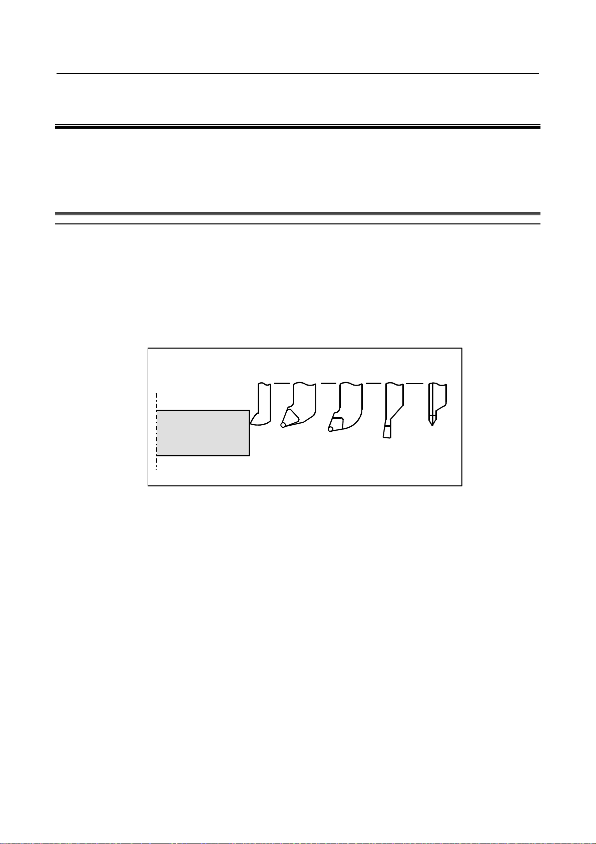
- Tool offset
Usually, several tools are used for machining one workpiece. The tools have different tool length. It is
very troublesome to change the program in accordance with the tools.
Therefore, the length of each tool used should be measured in advance. By setting the difference between
the length of the standard tool and the length of each tool in the CNC (see Chapter, “Setting and
Displaying Data” in the OPERATOR’S MANUAL (Common to Lathe System/Machining Center
System)), machining can be performed without altering the program even when the tool is changed. This
function is called tool offset.
Standard
tool
Rough
cutting
tool
Finishing
tool
Grooving
tool
Threading
tool
Workpiece
Fig. 1.1 (a) Tool offset
- 9 -
Page 24
2. PREPARATORY FUNCTION
(G FUNCTION)
PROGRAMMING B-64484EN-1/03
2 PREPARATORY FUNCTION (G FUNCTION)
A number following address G determines the meaning of the command for the concerned block.
G codes are divided into the following two types.
Type Meaning
One-shot G code The G code is effective only in the block in which it is specified.
Modal G code The G code is effective until another G code of the same group is specified.
(Example)
G01 and G00 are modal G codes in group 01.
G01 X_ ;
Z_ ; G01 is effective in this range.
X_ ;
G00 Z_ ; G00 is effective in this range.
X_ ;
G01 X_ ;
:
There are three G code systems in the lathe system : A,B, and C (Table 2 (a)). Select a G code system
using bits 6 (GSB) and 7 (GSC) parameter No. 3401. To use G code system B or C, the corresponding
option is needed. Generally, OPERATOR’S MANUAL describes the use of G code system A, except
when the described item can use only G code system B or C. In such cases, the use of G code system B or
C is described.
Explanation
1. When the clear state (bit 6 (CLR) of parameter No. 3402) is set at power-up or reset, the modal G
codes are placed in the states described below.
(1) The modal G codes are placed in the states marked with
(2) G20 and G21 remain unchanged when the clear state is set at power-up or reset.
(3) Which status G22 or G23 at power on is set by bit 7 (G23) of parameter No. 3402. However,
G22 and G23 remain unchanged when the clear state is set at reset.
(4) The user can select G00 or G01 by setting bit 0 (G01) of parameter No. 3402.
(5) The user can select G90 or G91 by setting bit 3 (G91) of parameter No. 3402.
When G code system B or C is used in the lathe system, setting bit 3 (G91) of parameter No.
3402 determines which code, either G90 or G91, is effective.
2. G codes other than G10 and G11 are one-shot G codes.
3. When a G code not listed in the G code list is specified, or a G code that has no corresponding
option is specified, alarm PS0010 occurs.
4. Multiple G codes can be specified in the same block if each G code belongs to a different group. If
multiple G codes that belong to the same group are specified in the same block, only the last G code
specified is valid.
5. If a G code belonging to group 01 is specified in a for drilling, the canned cycle for drilling is
cancelled. This means that the same state set by specifying G80 is set. Note that the G codes in
group 01 are not affected by a G code specifying a canned cycle.
6. When G code system A is used, absolute or incremental programming is specified not by a G code
(G90/G91) but by an address word (X/U, Z/W, C/H, Y/V). Only the initial level is provided at the
return point of the canned cycle for drilling..
7. G codes are indicated by group.
as indicated in Table.
- 10 -
Page 25
2.PREPARATORY FUNCTION
B-64484EN-1/03 PROGRAMMING
Table 2 (a) G code list
G code system
A B C
G00 G00 G00 Positioning (Rapid traverse)
G01 G01 G01 Linear interpolation (Cutting feed)
G02 G02 G02 Circular interpolation CW or helical interpolation CW
G03 G03 G03 Circular interpolation CCW or helical interpolation CCW
G02.2 G02.2 G02.2 Involute interpolation CW
G02.3 G02.3 G02.3 Exponential interpolation CW
G02.4 G02.4 G02.4 3-dimensional coordinate system conversion CW
G03.2 G03.2 G03.2 Involute interpolation CCW
G03.3 G03.3 G03.3 Exponential interpolation CCW
G03.4 G03.4 G03.4
G04 G04 G04 Dwell
G05 G05 G05
G05.1 G05.1 G05.1 AI contour control / Nano smoothing / Smooth interpolation
G05.4 G05.4 G05.4
G06.2 G06.2 G06.2 01 NURBS interpolation
G07 G07 G07 Hypothetical axis interpolation
G07.1
(G107)
G08 G08 G08 Advanced preview control
G09 G09 G09 Exact stop
G10 G10 G10 Programmable data input
G10.6 G10.6 G10.6 Tool retract and recover
G10.9 G10.9 G10.9 Programmable switching of diameter/radius specification
G11 G11 G11
G12.1
(G112)
G13.1
(G113)
G17 G17 G17 XpYp plane selection
G17.1 G17.1 G17.1 Plane conversion function
G18 G18 G18 ZpXp plane selection
G19 G19 G19
G20 G20 G70 Input in inch
G21 G21 G71
G22 G22 G22 Stored stroke check function on
G23 G23 G23
G25 G25 G25 Spindle speed fluctuation detection off
G26 G26 G26
G27 G27 G27 Reference position return check
G28 G28 G28 Return to reference position
G28.2 G28.2 G28.2 In-position check disable reference position return
G29 G29 G29 Movement from reference position
G30 G30 G30 2nd, 3rd and 4th reference position return
G30.1 G30.1 G30.1 Floating reference point return
G30.2 G30.2 G30.2
G31 G31 G31 Skip function
G31.8 G31.8 G31.8
G07.1
(G107)
G12.1
(G112)
G13.1
(G113)
G07.1
(G107)
G12.1
(G112)
G13.1
(G113)
Group Function
01
3-dimensional coordinate system conversion CCW
AI contour control (command compatible with high precision
00
00
21
16
06
09
08
00
contour control), High-speed cycle machining, High-speed
binary program operation
HRV3, 4 on/off
Cylindrical interpolation
Programmable data input mode cancel
Polar coordinate interpolation mode
Polar coordinate interpolation cancel mode
YpZp plane selection
Input in mm
Stored stroke check function off
Spindle speed fluctuation detection on
In-position check disable 2nd, 3rd, or 4th reference position
return
EGB-axis skip
(G FUNCTION)
- 11 -
Page 26
2. PREPARATORY FUNCTION
(G FUNCTION)
PROGRAMMING B-64484EN-1/03
Table 2 (a) G code list
G code system
A B C
G32 G33 G33 Threading
G34 G34 G34 Variable lead threading
G35 G35 G35 Circular threading CW
G36 G36 G36
G37 G37 G37
G37.1 G37.1 G37.1
G37.2 G37.2 G37.2
G38 G38 G38 Tool radius/tool nose radius compensation: with vector held
G39 G39 G39
G40 G40 G40 Tool radius/tool nose radius compensation : cancel
G41 G41 G41 Tool radius/tool nose radius compensation : left
G42 G42 G42 Tool radius/tool nose radius compensation : right
G41.2 G41.2 G41.2 3-dimensional cutter compensation : left (type 1)
G41.3 G41.3 G41.3
G41.4 G41.4 G41.4
G41.5 G41.5 G41.5
G41.6 G41.6 G41.6 3-dimensional cutter compensation : left (type 2)
G42.2 G42.2 G42.2 3-dimensional cutter compensation : right (type 1)
G42.4 G42.4 G42.4
G42.5 G42.5 G42.5
G42.6 G42.6 G42.6
G40.1 G40.1 G40.1 Normal direction control cancel mode
G41.1 G41.1 G41.1 Normal direction control left on
G42 .1 G42 .1 G42 .1
G43 G43 G43
G44 G44 G44
G43.1 G43.1 G43.1
G43.4 G43.4 G43.4
G43.5 G43.5 G43.5
G43.7
(G44.7)
G44.1 G44.1 G44.1
G49
(G49.1)
G43.7
(G44.7)
G49
(G49.1)
G43.7
(G44.7)
G49
(G49.1)
Group Function
Circular threading CCW (When bit 3 (G36) of parameter No.
3405 is set to 1) or Automatic tool offset (X axis) (When bit 3
(G36) of parameter No. 3405 is set to 0)
Automatic tool offset (Z axis) (When bit 3 (G36) of parameter
01
07
19
23
No. 3405 is set to 0)
Automatic tool offset (X axis) (When bit 3 (G36) of parameter
No. 3405 is set to 1)
Automatic tool offset (Z axis) (When bit 3 (G36) of parameter
No. 3405 is set to 1)
Tool radius/tool nose radius compensation: corner rounding
interpolation
3-dimensional cutter compensation :
(leading edge offset)
3-dimensional cutter compensation : left (type 1)
(FS16i-compatible command)
3-dimensional cutter compensation : left (type 1)
(FS16i-compatible command)
3-dimensional cutter compensation : right (type 1)
(FS16i-compatible command)
3-dimensional cutter compensation : right (type 1)
(FS16i-compatible command)
3-dimensional cutter compensation : right (type 2)
Normal direction control right on
Tool length compensation +
(Bit 3 (TCT) of parameter No. 5040 must be "1".)
Tool length compensation -
(Bit 3 (TCT) of parameter No. 5040 must be "1".)
Tool length compensation in tool axis direction
(Bit 3 (TCT) of parameter No. 5040 must be "1".)
Tool center point control (type 1)
(Bit 3 (TCT) of parameter No. 5040 must be "1".)
Tool center point control (type 2)
(Bit 3 (TCT) of parameter No. 5040 must be "1".)
Tool offset
(Bit 3 (TCT) of parameter No. 5040 must be "1".)
Tool offset conversion
(Bit 3 (TCT) of parameter No. 5040 must be "1".)
Tool length compensation cancel
(Bit 3 (TCT) of parameter No. 5040 must be "1".)
- 12 -
Page 27
2.PREPARATORY FUNCTION
B-64484EN-1/03 PROGRAMMING
Table 2 (a) G code list
G code system
A B C
G50 G92 G92 Coordinate system setting or max spindle speed clamp
G50.3 G92.1 G92.1
- G50 G50 Scaling cancel
- G51 G51
G50.1 G50.1 G50.1 Programmable mirror image cancel
G51.1 G51.1 G51.1
G50.2
(G250)
G51.2
(G251)
G50.4 G50.4 G50.4 Cancel synchronous control
G50.5 G50.5 G50.5 Cancel composite control
G50.6 G50.6 G50.6 Cancel superimposed control
G51.4 G51.4 G51.4 Start synchronous control
G51.5 G51.5 G51.5 Start composite control
G51.6 G51.6 G51.6 Start superimposed control
G52 G52 G52 Local coordinate system setting
G53 G53 G53 Machine coordinate system setting
G53.1 G53.1 G53.1 Tool axis direction control
G53.6 G53.6 G53.6
G54
(G54.1)
G55 G55 G55 Workpiece coordinate system 2 selection
G56 G56 G56 Workpiece coordinate system 3 selection
G57 G57 G57 Workpiece coordinate system 4 selection
G58 G58 G58 Workpiece coordinate system 5 selection
G59 G59 G59
G54.4 G54.4 G54.4 26 Workpiece setting error compensation
G60 G60 G60 00 Single direction positioning
G61 G61 G61 Exact stop mode
G62 G62 G62 Automatic corner override mode
G63 G63 G63 Tapping mode
G64 G64 G64
G65 G65 G65 00 Macro call
G66 G66 G66 Macro modal call A
G66.1 G66.1 G66.1 Macro modal call B
G67 G67 G67
G68 G68 G68 04 Mirror image on for double turret or balance cutting mode
G68.1 G68.1 G68.1
G68.2 G68.2 G68.2 Tilted working plane command
G68.3 G68.3 G68.3 Tilted working plane command by tool axis direction
G68.4 G68.4 G68.4
G69 G69 G69
G69.1 G69.1 G69.1 17
G50.2
(G250)
G51.2
(G251)
G54
(G54.1)
G50.2
(G250)
G51.2
(G251)
G54
(G54.1)
Group Function
00
18
22
20
00
14
15
12
17
04 Mirror image off for double turret or balance cutting mode
Workpiece coordinate system preset
Scaling
Programmable mirror image
Polygon turning cancel
Polygon turning
Tool center point retention type tool axis direction control
Workpiece coordinate system 1 selection
Workpiece coordinate system 6 selection
Cutting mode
Macro modal call A/B cancel
Coordinate system rotation start or 3-dimensional coordinate
system conversion mode on
Tilted working plane command (incremental multi-command)
cancel
Coordinate system rotation cancel or 3-dimensional
coordinate system conversion mode off
(G FUNCTION)
- 13 -
Page 28
2. PREPARATORY FUNCTION
(G FUNCTION)
PROGRAMMING B-64484EN-1/03
Table 2 (a) G code list
G code system
A B C
G70 G70 G72 Finishing cycle
G71 G71 G73 Stock removal in turning
G72 G72 G74 Stock removal in facing
G73 G73 G75 Pattern repeating cycle
G74 G74 G76 End face peck drilling cycle
G75 G75 G77 Outer diameter/internal diameter drilling cycle
G76 G76 G78
G71 G71 G72 Traverse grinding cycle
G72 G72 G73 Traverse direct sizing/grinding cycle
G73 G73 G74 Oscillation grinding cycle
G74 G74 G75
G80 G80 G80 10
G81.1 G81.1 G81.1 00 Chopping function/High precision oscillation function
G80.4 G80.4 G80.4 Electronic gear box: synchronization cancellation
G81.4 G81.4 G81.4
G80.5 G80.5 G80.5 Electronic gear box 2 pair: synchronization cancellation
G81.5 G81.5 G81.5
G81 G81 G81
G82 G82 G82 Counter boring (FS15-T format)
G83 G83 G83 Cycle for face drilling
G83.1 G83.1 G83.1 High-speed peck drilling cycle (FS15-T format)
G83.5 G83.5 G83.5 High-speed peck drilling cycle
G83.6 G83.6 G83.6 Peck drilling cycle
G84 G84 G84 Cycle for face tapping
G84.2 G84.2 G84.2 Rigid tapping cycle (FS15-T format)
G85 G85 G85 Cycle for face boring
G87 G87 G87 Cycle for side drilling
G87.5 G87.5 G87.5 High-speed peck drilling cycle
G87.6 G87.6 G87.6 Peck drilling cycle
G88 G88 G88 Cycle for side tapping
G89 G89 G89
G90 G77 G20 Outer diameter/internal diameter cutting cycle
G92 G78 G21 Threading cycle
G94 G79 G24
G91.1 G91.1 G91.1 00 Maximum specified incremental amount check
G96 G96 G96 Constant surface speed control
G97 G97 G97
G96.1 G96.1 G96.1 Spindle indexing execution (waiting for completion)
G96.2 G96.2 G96.2 Spindle indexing execution (not waiting for completion)
G96.3 G96.3 G96.3 Spindle indexing completion check
G96.4 G96.4 G96.4
G93 G93 G93 Inverse time feed
G98 G94 G94 Feed per minute
G99 G95 G95
- G90 G90 Absolute programming
- G91 G91
- G98 G98 Canned cycle : return to initial level
- G99 G99
Group Function
00
Multiple-thread cutting cycle
01
Oscillation direct sizing/grinding cycle
Canned cycle cancel for drilling
Electronic gear box : synchronization cancellation
28
27
10
01
02
00
05
03
11
Electronic gear box: synchronization start
Electronic gear box 2 pair: synchronization start
Spot drilling (FS15-T format)
Electronic gear box : synchronization start
Cycle for side boring
End face turning cycle
Constant surface speed control cancel
SV speed control mode ON
Feed per revolution
Incremental programming
Canned cycle : return to R point level
- 14 -
Page 29
B-64484EN-1/03 PROGRAMMING 3.INTERPOLATION FUNCTION
δ
α
δ
3 INTERPOLATION FUNCTION
Chapter 3, "INTERPOLATION FUNCTION", consists of the following sections:
3.1 CONSTANT LEAD THREADING (G32).........................................................................................15
3.2 CONTINUOUS THREADING...........................................................................................................18
3.3 MULTIPLE THREADING.................................................................................................................19
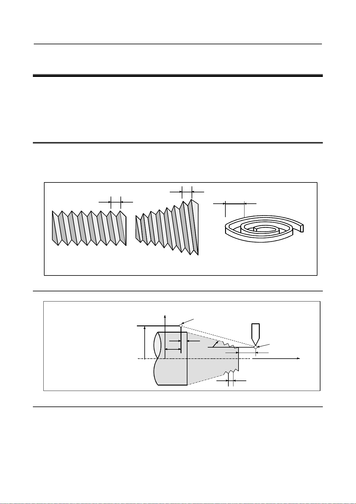
3.1 CONSTANT LEAD THREADING (G32)
Tapered screws and scroll threads in addition to equal lead straight threads can be cut by using a G32
command.
The spindle speed is read from the position coder on the spindle in real time and converted to a cutting
feedrate for feed-per minute mode, which is used to move the tool.
L
Format
G32IP_F_;
IP
F _: Lead of the long axis
(always radius programming)
Straight thread
_: End point
L
Tapered screw
Fig. 3.1 (a) Thread types
X axis
X
Z
0
End point_
2
L
Scroll thread
Start point
1
Z axis
L
Fig. 3.1 (b) Example of threading
Explanation
In general, threading is repeated along the same tool path in rough cutting through finish cutting for a
screw. Since threading starts when the position coder mounted on the spindle outputs a
one-spindle-rotation signal, threading is started at a fixed point and the tool path on the workpiece is
unchanged for repeated threading. Note that the spindle speed must remain constant from rough cutting
through finish cutting. If not, incorrect thread lead will occur.
- 15 -
Page 30
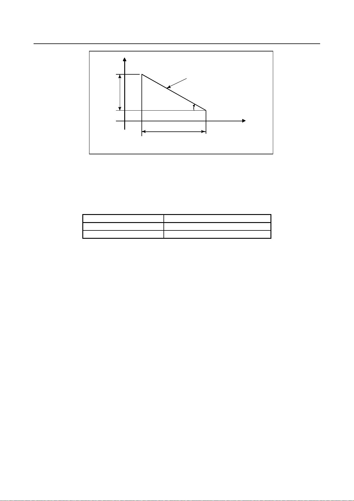
3.INTERPOLATION FUNCTION PROGRAMMING B-64484EN-1/03
X
X
α
α
≤
Tapered thread
L
Z
LZ
45° lead is LZ
lead is LX
α≥45°
Fig. 3.1 (c) LZ and LX of a tapered thread
In general, the lag of the servo system, etc. will produce somewhat incorrect leads at the starting and
ending points of a thread cut. To compensate for this, a threading length somewhat longer than required
should be specified.
Table 3.1 (a) lists the ranges for specifying the thread lead.
Table 3.1 (a) Ranges of lead sizes that can be specified
Least command increment
Metric input 0.0001 to 500.0000 mm
Inch input 0.000001 to 9.999999 inch
- 16 -
Page 31

B-64484EN-1/03 PROGRAMMING 3.INTERPOLATION FUNCTION
φ
Example
1. Straight threading
The following values are used in programming :
X axis
δ
2
2.Tapered threading
X axis
φ
50
0
δ
φ
43
30
30mm
δ
1
Zaxis
70
2
δ
1
Zaxis
14
40
Thread lead :4mm
Depth of cut :1mm (cut twice)
(Metric input, diameter programming)
G00 U-62.0 ;
G32 W-74.5 F4.0 ;
G00 U62.0 ;
W74.5 ;
U-64.0 ;
(For the second cut, cut 1mm more)
G32 W-74.5 ;
G00 U64.0 ;
W74.5 ;
The following values are used in programming :
Thread lead : 3.5mm in the direction of the Z axis
Cutting depth in the X axis direction is 1mm (cut twice)
(Metric input, diameter programming)
G 00 X 12.0 Z72 .0 ;
G 32 X 41.0 Z29 .0 F3.5 ;
G 00 X 50.0 ;
Z 72.0 ;
X 10.0 ;
(Cut 1mm more for the second cut)
G 32 X 39.0 Z29 .0 ;
G 00 X 50.0 ;
Z 72.0 ;
δ
δ
δ
=2mm
1
δ
=1mm
2
=3mm
1
=1.5mm
2
WARNING
1 Feedrate override is effective (fixed at 100%) during threading.
2 It is very dangerous to stop feeding the thread cutter without stopping the
spindle. This will suddenly increase the cutting depth. Thus, the feed hold
function is ineffective while threading. If the feed hold button is pressed during
threading, the tool will stop after a block not specifying threading is executed as
if the SINGLE BLOCK button were pushed. However, the feed hold lamp (SPL
lamp) lights when the FEED HOLD button on the machine control panel is
pushed. Then, when the tool stops, the lamp is turned off (Single Block stop
status).
3 When the FEED HOLD button is pressed again in the first block after threading
mode that does not specify threading (or the button has been held down), the
tool stops immediately at the block that does not specify threading.
4 When threading is executed in the single block status, the tool stops after
execution of the first block not specifying threading.
- 17 -
Page 32

3.INTERPOLATION FUNCTION PROGRAMMING B-64484EN-1/03
WARNING
5 When the mode was changed from automatic operation to manual operation
during threading, the tool stops at the first block not specifying threading as
when the feed hold button is pushed as mentioned in Warning 3.
However, when the mode is changed from one automatic operation mode to
another, the tool stops after execution of the block not specifying threading as for
the single block mode in Note 4.
6 When the previous block was a threading block, cutting will start immediately
without waiting for detection of the one-spindle-rotation signal even if the present
block is a threading block.
(Example)
G00 Z0.0 X50.0 ; One-rotation signal is
G32 Z10.0 F_ ; : Detected
Z20.0 ; : Not detected
G32 Z30.0 ; : Not detected
7 Because the constant surface speed control is effective during scroll thread or
tapered screw cutting and the spindle speed changes, the correct thread lead
may not be cut. Therefore, do not use the constant surface speed control during
threading. Instead, use G97.
8 A movement block preceding the threading block must not specify chamfering or
corner R.
9 A threading block must not specifying chamfering or corner R.
10 The spindle speed override function is disabled during threading. The spindle
speed is fixed at 100%.
11 Thread cycle retract function is ineffective to G32.
12 If tool offset (with the T code or G43.7) is specified in a block for threading, alarm
PS0509, “TOOL OFFSET COMMAND IS NOT AVAILABLE”, is issued.
3.2 CONTINUOUS THREADING
Threading blocks can be programmed successively to eliminate a discontinuity due to a discontinuous
movement in machining by adjacent blocks.
Explanation
Since the system is controlled in such a manner that the synchronism with the spindle does not deviate in
the joint between blocks wherever possible, it is possible to performed special threading operation in
which the lead and shape change midway.
G32
G32
Fig. 3.2 (a) Continuous threading (Example of G32 in G code system A)
Even when the same section is repeated for threading while changing the depth of cut, this system allows
a correct machining without impairing the threads.
G32
- 18 -
Page 33

B-64484EN-1/03 PROGRAMMING 3.INTERPOLATION FUNCTION
3.3 MULTIPLE THREADING
Using the Q address to specify an angle between the one-spindle-rotation signal and the start of threading
shifts the threading start angle, making it possible to produce multiple-thread screws with ease.
L
L : Lead
Fig. 3.3 (a) Multiple thread screws.
Format
(Constant lead threading)
G32 IP _ F_ Q_ ;
IP : End point
F_ : Lead in longitudinal direction
G32 IP _ Q_ ;
Q_ : Threading start angle
Explanation
- Available threading commands
G32: Constant lead threading
G34: Variable lead threading
G76: Multiple threading cycle
G92: Threading cycle
Limitation
- Start angle
The start angle is not a continuous state (modal) value. It must be specified each time it is used. If a
value is not specified, 0 is assumed.
- Start angle increment
The start angle (Q) increment is 0.001 degrees. Note that no decimal point can be specified.
Example:
For a shift angle of 180 degrees, specify Q180000.
Q180.000 cannot be specified, because it contains a decimal point.
- Specifiable start angle range
A start angle (Q) of between 0 and 360000 (in 0.001-degree units) can be specified. If a value
greater than 360000 (360 degrees) is specified, it is rounded down to 360000 (360 degrees).
- Multiple threading cycle (G76)
For the G76 multiple threading cycle command, always use the FS15 tape format.
- 19 -
Page 34

3.INTERPOLATION FUNCTION PROGRAMMING B-64484EN-1/03
Example
Program for producing double-threaded screws (with start angles of 0 and 180
degrees)
X40.0 ;
W-38.0 F4.0 Q0 ;
X72.0 ;
W38.0 ;
X40.0 ;
W-38.0 F4.0Q180000 ;
X72.0 ;
W38.0 ;
- 20 -
Page 35

4.FUNCTIONS TO SIMPLIFY
B-64484EN-1/03 PROGRAMMING
PROGRAMMING
4 FUNCTIONS TO SIMPLIFY PROGRAMMING
Chapter 4, "FUNCTIONS TO SIMPLIFY PROGRAMMING", consists of the following sections:
4.1 CANNED CYCLE (G90, G92, G94)..................................................................................................21
4.2 MULTIPLE REPETITIVE CANNED CYCLE (G70-G76)...............................................................38
4.3 CANNED CYCLE FOR DRILLING .................................................................................................74
4.4 IN-POSITION CHECK SWITCHING FOR DRILLING CANNED CYCLE...................................83
4.5 RIGID TAPPING................................................................................................................................90
4.6 CANNED GRINDING CYCLE (FOR GRINDING MACHINE)....................................................103
4.7 CHAMFERING AND CORNER R..................................................................................................113
4.8 MIRROR IMAGE FOR DOUBLE TURRET (G68, G69)...............................................................119
4.9 DIRECT DRAWING DIMENSION PROGRAMMING .................................................................120
4.1 CANNED CYCLE (G90, G92, G94)
There are three canned cycles : the outer diameter/internal diameter cutting canned cycle (G90), the
threading canned cycle (G92), and the end face turning canned cycle (G94).
NOTE
1 Explanatory figures in this section use the ZX plane as the selected plane,
diameter programming for the X-axis, and radius programming for the Z-axis.
When radius programming is used for the X-axis, change U/2 to U and X/2 to X.
2 A canned cycle can be performed on any plane (including parallel axes for plane
definition). When G-code system A is used, however, U, V, and W cannot be set
as a parallel axis.
3 The direction of the length means the direction of the first axis on the plane as
follows:
ZX plane: Z-axis direction
YZ plane: Y-axis direction
XY plane: X-axis direction
4 The direction of the end face means the direction of the second axis on the
plane as follows:
ZX plane: X-axis direction
YZ plane: Z-axis direction
XY plane: Y-axis direction
- 21 -
Page 36

4. FUNCTIONS TO SIMPLIFY
A’A
PROGRAMMING
PROGRAMMING B-64484EN-1/03
4.1.1 Outer Diameter/Internal Diameter Cutting Cycle (G90)
This cycle performs straight or taper cutting in the direction of the length.
4.1.1.1 Straight cutting cycle
Format
G90X(U)_Z(W)_F_;
X_,Z_ : Coordinates of the cutting end point (point A' in the Fig. 4.1.1.1 (a)) in the direction
of the length
U_,W_ : Travel distance to the cutting end point (point A' in the Fig. 4.1.1.1 (a)) in the
direction of the length
F_ : Cutting feedrate
X axis
Z
W
4(R)
3(F)
2(F)
Fig. 4.1.1.1 (a) Straight cutting cycle
1(R)
(R)....Rapid traverse
(F)....Cutting fee d
U/2
X/2
Z axis
Explanation
- Operations
A straight cutting cycle performs four operations:
(1) Operation 1 moves the tool from the start point (A) to the specified coordinate of the second axis on
the plane (specified X-coordinate for the ZX plane) in rapid traverse.
(2) Operation 2 moves the tool to the specified coordinate of the first axis on the plane (specified
Z-coordinate for the ZX plane) in cutting feed. (The tool is moved to the cutting end point (A') in the
direction of the length.)
(3) Operation 3 moves the tool to the start coordinate of the second axis on the plane (start X-coordinate
for the ZX plane) in cutting feed.
(4) Operation 4 moves the tool to the start coordinate of the first axis on the plane (start Z-coordinate for
the ZX plane) in rapid traverse. (The tool returns to the start point (A).)
NOTE
In single block mode, operations 1, 2, 3 and 4 are performed by pressing the
cycle start button once.
- Canceling the mode
To cancel the canned cycle mode, specify a group 01 G code other than G90, G92, or G94.
- 22 -
Page 37

4.FUNCTIONS TO SIMPLIFY
A
A
B-64484EN-1/03 PROGRAMMING
PROGRAMMING
4.1.1.2 Taper cutting cycle
Format
G90 X(U)_Z(W)_R_F_;
X_,Z_ : Coordinates of the cutting end point (point A' in the Fig. 4.1.1.2 (a)) in the direction
of the length
U_,W_ : Travel distance to the cutting end point (point A' in the Fig. 4.1.1.2 (a)) in the
direction of the length
R_ : Taper amount (R in the Fig. 4.1.1.2 (a))
F_ : Cutting feedrate
X axis
(R) ....Rapid traverse
4(R)
(F)....Cutting feed
3(F)
U/2
X/2
Z
’
W
Fig. 4.1.1.2 (a) Taper cutting cycle
2(F)
1(R)
R
Z axis
Explanation
The figure of a taper is determined by the coordinates of the cutting end point (A') in the direction of the
length and the sign of the taper amount (address R). For the cycle in the Fig. 4.1.1.2 (a), a minus sign is
added to the taper amount.
NOTE
The increment system of address R for specifying a taper depends on the
increment system for the reference axis. Specify a radius value at R.
- Operations
A taper cutting cycle performs the same four operations as a straight cutting cycle.
However, operation 1 moves the tool from the start point (A) to the position obtained by adding the taper
amount to the specified coordinate of the second axis on the plane (specified X-coordinate for the ZX
plane) in rapid traverse.
Operations 2, 3, and 4 after operation 1 are the same as for a straight cutting cycle.
NOTE
In single block mode, operations 1, 2, 3, and 4 are performed by pressing the
cycle start button once.
- Relationship between the sign of the taper amount and tool path
The tool path is determined according to the relationship between the sign of the taper amount (address R)
and the cutting end point in the direction of the length in the absolute or incremental programming as
Table 4.1.1.2 (a).
- 23 -
Page 38

4. FUNCTIONS TO SIMPLIFY
X
PROGRAMMING
PROGRAMMING B-64484EN-1/03
Table 4.1.1.2 (a)
Outer diameter machining Internal diameter machining
1. U < 0, W < 0, R < 0 2. U > 0, W < 0, R > 0
X
U/2
Z
3(F)
X
2(F)
4(R)
1(R)
R
W
X
X
Z
U/2 3(F)
W
2(F)
4(R)
U/2
X
3. U < 0, W < 0, R > 0
at |R|≤|U/2|
Z
3(F)
4(R)
2(F)
W
1(R)
X
R
4. U > 0, W < 0, R < 0
at |R|≤|U/2|
X
Z
U/2
3(F)
W
2(F)
4(R)
- Canceling the mode
To cancel the canned cycle mode, specify a group 01 G code other than G90, G92, or G94.
R
1(R)
R
1(R)
4.1.2 Threading Cycle (G92)
4.1.2.1 Straight threading cycle
Format
G92 X(U)_Z(W)_F_Q_;
X_,Z_ : Coordinates of the cutting end point (point A' in the Fig. 4.1.2.1 (a)) in the direction
of the length
U_,W_ : Travel distance to the cutting end point (point A' in the Fig. 4.1.2.1 (a)) in the
direction of the length
Q_ : Angle for shifting the threading start angle
(Increment: 0.001 degrees, Valid setting range: 0 to 360 degrees)
F_ : Thread lead (L in the Fig. 4.1.2.1 (a))
- 24 -
Page 39

4.FUNCTIONS TO SIMPLIFY
)
)
)
A
A
B-64484EN-1/03 PROGRAMMING
X axis
Z
3(R
’
W
4(R)
2(F
L
1(R
X/2
(R) ... Rapid traverse
(F).... Cutting feed
PROGRAMMING
U/2
Z axis
Approx.
45°
r
Detailed chamfered thread
Fig. 4.1.2.1 (a) Straight threading
(The chamfered angle in the left figure is 45
degrees or less because of the delay in the
servo system.)
Explanation
The ranges of thread leads and restrictions related to the spindle speed are the same as for threading with
G32.
- Operations
A straight threading cycle performs four operations:
(1) Operation 1 moves the tool from the start point (A) to the specified coordinate of the second axis on
the plane (specified X-coordinate for the ZX plane) in rapid traverse.
(2) Operation 2 moves the tool to the specified coordinate of the first axis on the plane (specified
Z-coordinate for the ZX plane) in cutting feed. At this time, thread chamfering is performed.
(3) Operation 3 moves the tool to the start coordinate of the second axis on the plane (start X-coordinate
for the ZX plane) in rapid traverse. (Retraction after chamfering)
(4) Operation 4 moves the tool to the start coordinate of the first axis on the plane (start Z-coordinate for
the ZX plane) in rapid traverse. (The tool returns to the start point (A).)
CAUTION
Notes on this threading are the same as in threading in G32. However, a stop by
feed hold is as follows; Stop after completion of path 3 of threading cycle.
NOTE
In the single block mode, operations 1, 2, 3, and 4 are performed by pressing
cycle start button once.
- Canceling the mode
To cancel the canned cycle mode, specify a group 01 G code other than G90, G92, or G94.
- Acceleration/deceleration after interpolation for threading
Acceleration/deceleration after interpolation for threading is acceleration/deceleration of exponential
interpolation type. By setting bit 5 (THLx) of parameter No. 1610, the same acceleration/deceleration as
for cutting feed can be selected. (The settings of bits 1 (CTBx) and 0 (CTLx) of parameter No. 1610 are
followed.) However, as a time constant and FL feedrate, the settings of parameter No. 1626 and No. 1627
for the threading cycle are used.
- 25 -
Page 40

4. FUNCTIONS TO SIMPLIFY
PROGRAMMING
PROGRAMMING B-64484EN-1/03
- Time constant and FL feedrate for threading
The time constant for acceleration/deceleration after interpolation for threading specified in parameter No.
1626 and the FL feedrate specified in parameter No. 1627 are used.
The FL feedrate is valid only for exponential acceleration/deceleration after interpolation.
- Thread chamfering
Thread chamfering can be performed. A signal from the machine tool, initiates thread chamfering. The
chamfering distance r is specified in a range from 0.1L to 12.7L in 0.1L increments by parameter No.
5130. (In the above expression, L is the thread lead.)
A thread chamfering angle between 1 to 89 degrees can be specified in parameter No. 5131. When a
value of 0 is specified in the parameter, an angle of 45 degrees is assumed.
For thread chamfering, the same type of acceleration/deceleration after interpolation, time constant for
acceleration/deceleration after interpolation, and FL feedrate as for threading are used.
NOTE
Common parameters for specifying the amount and angle of thread chamfering
are used for this cycle and threading cycle with G76.
- Retraction after chamfering
The Table 4.1.2.1 (a) lists the feedrate, type of acceleration/deceleration after interpolation, and time
constant of retraction after chamfering.
Table 4.1.2.1 (a)
Bit 0 (CFR) of
parameter No. 1611
0 Other than 0
0 0
1
Parameter No.
1466
Description
Uses the type of acceleration/deceleration after interpolation for threading,
time constant for threading (parameter No. 1626), FL feedrate (parameter
No. 1627), and retraction feedrate specified in parameter No. 1466.
Uses the type of acceleration/deceleration after interpolation for threading,
time constant for threading (parameter No. 1626), FL feedrate (parameter
No. 1627), and rapid traverse rate specified in parameter No. 1420.
Before retraction a check is made to see that the specified feedrate has
become 0 (delay in acceleration/deceleration is 0), and the type of
acceleration/deceleration after interpolation for rapid traverse is used
together with the rapid traverse time constant and the rapid traverse rate
(parameter No. 1420).
By setting bit 4 (ROC) of parameter No. 1403 to 1, rapid traverse override can be disabled for the feedrate
of retraction after chamfering.
NOTE
During retraction, the machine does not stop with an override of 0% for the
cutting feedrate regardless of the setting of bit 4 (RF0) of parameter No. 1401.
- Shifting the start angle
Address Q can be used to shift the threading start angle.
The start angle (Q) increment is 0.001 degrees and the valid setting range is between 0 and 360 degrees.
No decimal point can be specified.
- Feed hold in a threading cycle
When the threading cycle retract function is not used, the machine stops at the end point of retraction
after chamfering (end point of operation 3) by feed hold applied during threading.
- 26 -
Page 41

4.FUNCTIONS TO SIMPLIFY
B-64484EN-1/03 PROGRAMMING
PROGRAMMING
- Threading cycle retract
When the "threading cycle retract" optional function is used, feed hold may be applied during threading
(operation 2). In this case, the tool immediately retracts with chamfering and returns to the start point on
the second axis (X-axis), then the first axis (Z-axis) on the plane.
X axis
Z axis
Rapid traverse
Cutting feed
Ordinary cycle
Motion at feed hold
Start point
Feed hold is effected here.
The chamfered angle is the same as that at the end point.
CAUTION
Another feed hold cannot be made during retreat.
- Inch threading
Inch threading specified with address E is not allowed.
4.1.2.2 Taper threading cycle
Format
G92 X(U)_Z(W)_R_F_Q_;
X_,Z_ : Coordinates of the cutting end point (point A' in the Fig. 4.1.2.2 (a)) in the direction
of the length
U_,W_ : Travel distance to the cutting end point (point A' in the Fig. 4.1.2.2 (a)) in the
direction of the length
Q_ : Angle for shifting the threading start angle
(Increment: 0.001 degrees, Valid setting range: 0 to 360 degrees)
R_ : Taper amount (R in the Fig. 4.1.2.2 (a))
F_ : Thread lead (L in the Fig. 4.1.2.2 (a))
- 27 -
Page 42

4. FUNCTIONS TO SIMPLIFY
A
A
A
PROGRAMMING
PROGRAMMING B-64484EN-1/03
X axis
U/2
X/2
Z
R
’
pprox. 45
r
3(R)
°
W
4(R)
1(R)
2(F)
L
(The chamfered angle in the left figure
is 45 degrees or less because of the
delay in the servo system.)
(R)....Rapi d t r averse
(F)....Cutting feed
Z axis
Detailed chamfered thread
Fig. 4.1.2.2 (a) Taper threading cycle
Explanation
The ranges of thread leads and restrictions related to the spindle speed are the same as for threading with
G32.
The figure of a taper is determined by the coordinates of the cutting end point (A') in the direction of the
length and the sign of the taper amount (address R). For the cycle in the Fig. 4.1.2.2 (a), a minus sign is
added to the taper amount.
NOTE
The increment system of address R for specifying a taper depends on the
increment system for the reference axis. Specify a radius value at R.
- Operations
A taper threading cycle performs the same four operations as a straight threading cycle.
However, operation 1 moves the tool from the start point (A) to the position obtained by adding the taper
amount to the specified coordinate of the second axis on the plane (specified X-coordinate for the ZX
plane) in rapid traverse.
Operations 2, 3, and 4 after operation 1 are the same as for a straight threading cycle.
CAUTION
Notes on this threading are the same as in threading in G32. However, a stop by
feed hold is as follows; Stop after completion of path 3 of threading cycle.
- 28 -
Page 43

4.FUNCTIONS TO SIMPLIFY
X
B-64484EN-1/03 PROGRAMMING
PROGRAMMING
NOTE
In the single block mode, operations 1, 2, 3, and 4 are performed by pressing
cycle start button once.
- Relationship between the sign of the taper amount and tool path
The tool path is determined according to the relationship between the sign of the taper amount (address R)
and the cutting end point in the direction of the length in the absolute or incremental programming as
Table 4.1.2.2 (a).
Table 4.1.2.2 (a)
Outer diameter machining Internal diameter machining
1. U < 0, W < 0, R < 0 2. U > 0, W < 0, R > 0
X
U/2
X
Z
3(F)
2(F)
4(R)
1(R)
R
W
X
X
Z
U/2 3(F)
W
2(F)
4(R)
U/2
X
3. U < 0, W < 0, R > 0
at |R|≤|U/2|
Z
3(F)
4(R)
2(F)
W
1(R)
X
R
4. U > 0, W < 0, R < 0
at |R|≤|U/2|
X
Z
U/2
3(F)
W
2(F)
4(R)
- Canceling the mode
To cancel the canned cycle mode, specify a group 01 G code other than G90, G92, or G94.
- Acceleration/deceleration after interpolation for threading
- Time constant and FL feedrate for threading
- Thread chamfering
- Retraction after chamfering
- Shifting the start angle
- Threading cycle retract
- Inch threading
See the pages on which a straight threading cycle is explained.
R
1(R)
R
1(R)
- 29 -
Page 44

4. FUNCTIONS TO SIMPLIFY
A
A
PROGRAMMING
PROGRAMMING B-64484EN-1/03
4.1.3 End Face Turning Cycle (G94)
4.1.3.1 Face cutting cycle
Format
G94 X(U)_Z(W)_F_;
X_,Z_ : Coordinates of the cutting end point (point A' in the Fig. 4.1.3.1 (a)) in the direction
of the end face
U_,W_ : Travel distance to the cutting end point (point A' in the Fig. 4.1.3.1 (a)) in the
direction of the end face
F_ : Cutting feedrate
X axis
1(R)
(R)... R apid traverse
(F) .... Cuttin g fe e d
2(F)
U/2
3(F)
’
X/2
Z
Fig. 4.1.3.1 (a) Face cutting cycle
W
4(R)
Z axis
Explanation
- Operations
A face cutting cycle performs four operations:
(1) Operation 1 moves the tool from the start point (A) to the specified coordinate of the first axis on the
plane (specified Z-coordinate for the ZX plane) in rapid traverse.
(2) Operation 2 moves the tool to the specified coordinate of the second axis on the plane (specified
X-coordinate for the ZX plane) in cutting feed. (The tool is moved to the cutting end point (A') in
the direction of the end face.)
(3) Operation 3 moves the tool to the start coordinate of the first axis on the plane (start Z-coordinate for
the ZX plane) in cutting feed.
(4) Operation 4 moves the tool to the start coordinate of the second axis on the plane (start X-coordinate
for the ZX plane) in rapid traverse. (The tool returns to the start point (A).)
NOTE
In single block mode, operations 1, 2, 3, and 4 are performed by pressing the
cycle start button once.
- Canceling the mode
To cancel the canned cycle mode, specify a group 01 G code other than G90, G92, or G94.
- 30 -
Page 45

4.FUNCTIONS TO SIMPLIFY
A
A
B-64484EN-1/03 PROGRAMMING
PROGRAMMING
4.1.3.2 Taper cutting cycle
Format
G94 X(U)_Z(W)_R_F_;
X_,Z_ : Coordinates of the cutting end point (point A' in the Fig. 4.1.3.2 (a)) in the direction
of the end face
U_,W_ : Travel distance to the cutting end point (point A' in the Fig. 4.1.3.2 (a)) in the
direction of the end face
R_ : Taper amount (R in the Fig. 4.1.3.2 (a))
F_ : Cutting feedrate
X axis
1(R)
U/2
X/2
Z
Fig. 4.1.3.2 (a) Taper cutting cycle
2(F)
R
’
4(R)
3(F)
W
(R)... Rap id tra ve rs e
(F) ... Cutting feed
Z axis
Explanation
The figure of a taper is determined by the coordinates of the cutting end point (A') in the direction of the
end face and the sign of the taper amount (address R). For the cycle in the Fig. 4.1.3.2 (a), a minus sign is
added to the taper amount.
NOTE
The increment system of address R for specifying a taper depends on the
increment system for the reference axis. Specify a radius value at R.
- Operations
A taper cutting cycle performs the same four operations as a face cutting cycle.
However, operation 1 moves the tool from the start point (A) to the position obtained by adding the taper
amount to the specified coordinate of the first axis on the plane (specified Z-coordinate for the ZX plane)
in rapid traverse.
Operations 2, 3, and 4 after operation 1 are the same as for a face cutting cycle.
NOTE
In single block mode, operations 1, 2, 3, and 4 are performed by pressing the
cycle start button once.
- 31 -
Page 46

4. FUNCTIONS TO SIMPLIFY
X
PROGRAMMING
PROGRAMMING B-64484EN-1/03
- Relationship between the sign of the taper amount and tool path
The tool path is determined according to the relationship between the sign of the taper amount (address R)
and the cutting end point in the direction of the end face in the absolute or incremental programming as
Table 4.1.3.2 (a).
Table 4.1.3.2 (a)
Outer diameter machining Internal diameter machining
1. U < 0, W < 0, R < 0 2. U > 0, W < 0, R < 0
1(R)
X
Z
Z
Z
R
W
U/2
Z
3. U < 0, W < 0, R > 0
X
Z
U/2
Z
2(F)
R
at |R|≤|W|
R
2(F)
3(F)
W
1(R)
3(F)
W
4(R)
4(R)
U/2
2(F)
4. U > 0, W < 0, R > 0
at |R|≤|W|
X
Z
U/2
Z
2(F)
R
- Canceling the mode
To cancel the canned cycle mode, specify a group 01 G code other than G90, G92, or G94.
4.1.4 How to Use Canned Cycles (G90, G92, G94)
3(F)
4(R)
1(R)
W
3(F)
4(R)
1(R)
An appropriate canned cycle is selected according to the shape of the material and the shape of the
product.
- Straight cutting cycle (G90)
Shape of material
Shape of
product
- 32 -
Page 47

4.FUNCTIONS TO SIMPLIFY
B-64484EN-1/03 PROGRAMMING
PROGRAMMING
- Taper cutting cycle (G90)
Shape of material
Shape of product
- Face cutting cycle (G94)
Shape of product
- Face taper cutting cycle (G94)
Shape of material
Shape of material
Shape of product
- 33 -
Page 48

4. FUNCTIONS TO SIMPLIFY
PROGRAMMING
PROGRAMMING B-64484EN-1/03
4.1.5 Canned Cycle and Tool Nose Radius Compensation
When tool nose radius compensation is applied, the tool nose center path and offset direction are as
shown below. At the start point of a cycle, the offset vector is canceled. Offset start-up is performed for
the movement from the start point of the cycle. The offset vector is temporarily canceled again at the
return to the cycle start point and offset is applied again according to the next move command. The offset
direction is determined depending of the cutting pattern regardless of the G41 or G42 mode.
Outer diameter/internal diameter cutting cycle (G90)
Tool nose radius center path
Offset direction
Tool nose radius
center path
Total tool nose
Total tool nose
Programmed path
4
5
1
End face cutting cycle (G94)
Tool nose radius center path
Tool nose radius
center path
Total tool nose
4
5
8
6
8
0
3
7
2
Total tool
nose
Offset direction
0
3
7
1
6
Total tool nose
Programmed path
Total tool
nose
Threading cycle (G92)
Tool nose radius compensation cannot be applied.
2
- 34 -
Page 49

4.FUNCTIONS TO SIMPLIFY
B-64484EN-1/03 PROGRAMMING
PROGRAMMING
Differences between this CNC and the FANUC Series 16i/18i/21i
NOTE
This CNC is the same as the FANUC Series 16i/18i/21i in the offset direction,
but differs from the series in the tool nose radius center path.
- For this CNC
Cycle operations of a canned cycle are replaced with G00 or G01. In the first
block to move the tool from the start point, start-up is performed. In the last
block to return the tool to the start point, offset is canceled.
- For the FANUC Series 16i/18i/21i
This series differs from this CNC in operations in the block to move the tool
from the start point and the last block to return it to the start point. For details,
refer to "FANUC Series 16i/18i/21i Operator's Manual."
How compensation is applied for the FANUC Series 16i/18i/21i
G90 G94
Tool nose radius center path
4,8,3
5,0,7
4
5
0
8
3
7
Tool nose radius center path
4,8,3
5,0,7
4
5
0
8
3
7
1,6,2
Total tool
4,5,1
nose
Programmed path
2
1
6
8,0,6
3,7,2
1,6,2
Total tool
nose
Programmed path
1
4,5,1
2
6
8,0,6
3,7,2
4.1.6 Restrictions on Canned Cycles
Limitation
- Modal
Since data items X (U), Z (W), and R in a canned cycle are modal values common to G90, G92, and G94.
For this reason, if a new X (U), Z (W), or R value is not specified, the previously specified value is
effective.
Thus, when the travel distance along the Z-axis does not vary as shown in the program example below, a
canned cycle can be repeated only by specifying the travel distance along the X-axis.
- 35 -
Page 50

4. FUNCTIONS TO SIMPLIFY
PROGRAMMING
PROGRAMMING B-64484EN-1/03
Example
X axis
0
The cycle in the above figure is executed by the following program:
N030 G90 U-8.0 W-66.0 F0.4;
N031 U-16.0;
N032 U-24.0;
N033 U-32.0;
66
4
8
12
Workpiece
16
The modal values common to canned cycles are cleared when a one-shot G code other than G04 is
specified.
Since the canned cycle mode is not canceled by specifying a one-shot G code, a canned cycle can be
performed again by specifying modal values. If no modal values are specified, no cycle operations are
performed.
When G04 is specified, G04 is executed and no canned cycle is performed.
- Block in which no move command is specified
In a block in which no move command is specified in the canned cycle mode, a canned cycle is also
performed. For example, a block containing only EOB or a block in which none of the M, S, and T codes,
and move commands are specified is of this type of block. When an M, S, or T code is specified in the
canned cycle mode, the corresponding M, S, or T function is executed together with the canned cycle. If
this is inconvenient, specify a group 01 G code (G00 or G01) other than G90, G92, or G94 to cancel the
canned cycle mode, and specify an M, S, or T code, as in the program example below. After the
corresponding M, S, or T function has been executed, specify the canned cycle again.
Example
N003 T0101;
:
:
N010 G90 X20.0 Z10.0 F0.2;
N011 G00 T0202;
Cancels the canned cycle mode.
←
N012 G90 X20.5 Z10.0;
- Plane selection command
Specify a plane selection command (G17, G18, or G19) before setting a canned cycle or specify it in the
block in which the first canned cycle is specified.
If a plane selection command is specified in the canned cycle mode, the command is executed, but the
modal values common to canned cycles are cleared.
If an axis which is not on the selected plane is specified, alarm PS0330, “ILLEGAL AXIS COMMAND
IS IN THE TURNING CANNED CYCLE” is issued.
- Parallel axis
When G code system A is used, U, V, and W cannot be specified as a parallel axis.
- 36 -
Page 51

4.FUNCTIONS TO SIMPLIFY
)
)
B-64484EN-1/03 PROGRAMMING
PROGRAMMING
- Reset
If a reset operation is performed during execution of a canned cycle when any of the following states for
holding a modal G code of group 01 is set, the modal G code of group 01 is replaced with the G01 mode:
• Reset state (bit 6 (CLR) of parameter No. 3402 = 0)
• Cleared state (bit 6 (CLR) of parameter No. 3402 = 1) and state where the modal G code of group 01
is held at reset time (bit 1 (C01) of parameter No. 3406 = 1)
Example of operation)
If a reset is made during execution of a canned cycle (X0 block) and the X20.Z1. command is
executed, linear interpolation (G01) is performed instead of the canned cycle.
- Manual intervention
After manual intervention is performed with the manual absolute on command before the execution of a
canned cycle or after the stop of the execution, when a cycle operation starts, the manual intervention
amount is canceled even with an incremental cycle start command.
Example of G94
Cancellation
2(F
3(F)
1(R)
Manual intervention
4(R
- 37 -
Page 52

4. FUNCTIONS TO SIMPLIFY
PROGRAMMING
PROGRAMMING B-64484EN-1/03
4.2 MULTIPLE REPETITIVE CANNED CYCLE (G70-G76)
The multiple repetitive canned cycle is canned cycles to make CNC programming easy. For instance, the
data of the finish work shape describes the tool path for rough machining. And also, a canned cycles for
the threading is available.
NOTE
1 Explanatory figures in this section use the ZX plane as the selected plane,
diameter programming for the X-axis, and radius programming for the Z-axis.
When radius programming is used for the X-axis, change U/2 to U and X/2 to X.
2 A multiple repetitive canned cycle can be performed on any plane (including
parallel axes for plane definition). When G-code system A is used, however, U,
V, and W cannot be set as a parallel axis.
- 38 -
Page 53

4.FUNCTIONS TO SIMPLIFY
B-64484EN-1/03 PROGRAMMING
PROGRAMMING
4.2.1 Stock Removal in Turning (G71)
There are two types of stock removals in turning : Type I and II.
To use type II, the "multiple repetitive canned cycle 2" optional function is required.
Format
ZpXp plane
G71 U(Δd) R(e) ;
G71 P(ns) Q(nf) U(Δu) W(Δw) F(f ) S(s ) T(t ) ;
N (ns) ;
...
N (nf) ;
YpZp plane
G71 W(Δd) R(e) ;
G71 P(ns) Q(nf) V(Δw) W(Δu) F(f ) S(s ) T(t ) ;
N (ns) ;
The move commands for the target figure from A
to A’ to B are specified in the blocks with
sequence numbers ns to nf.
...
N (nf) ;
XpYp plane
G71 V(Δd) R(e) ;
G71 P(ns) Q(nf) U(Δw) V(Δu) F(f ) S(s ) T(t ) ;
N (ns) ;
...
N (nf) ;
Δd : Depth of cut
The cutting direction depends on the direction AA'. This designation is modal and is
not changed until the other value is designated. Also this value can be specified by
the parameter No. 5132, and the parameter is changed by the program command.
e : Escaping amount
This designation is modal and is not changed until the other value is designated. Also
this value can be specified by the parameter No. 5133, and the parameter is changed
by the program command.
ns : Sequence number of the first block for the program of finishing shape.
nf : Sequence number of the last block for the program of finishing shape.
Δu : Distance of the finishing allowance in the direction of the second axis on the plane
(X-axis for the ZX plane)
Δw : Distance of the finishing allowance in the direction of the first axis on the plane (Z-axis
for the ZX plane)
f,s,t : Any F , S, or T function contained in blocks ns to nf in the cycle is ignored, and the F,
S, or T function in this G71 block is effective.
Unit Diameter/radius programming Sign
Depends on the increment
Δd
system for the reference axis.
Radius programming
Not
required
Decimal point
input
Allowed
- 39 -
Page 54

4. FUNCTIONS TO SIMPLIFY
A
Δ
Δ
A’Δ
PROGRAMMING
PROGRAMMING B-64484EN-1/03
Unit Diameter/radius programming Sign
Depends on the increment
e
system for the reference axis.
Depends on the increment
Δu
system for the reference axis.
Depends on the increment
Δw
system for the reference axis.
Radius programming
Depends on diameter/radius programming
for the second axis on the plane.
Depends on diameter/radius programming
for the first axis on the plane.
Not
required
Required Allowed
Required Allowed
Decimal point
B
(F)
Target figure
+X
45°
(R)
(R)
e
(F)
C
d
u/2
input
Allowed
(F): Cutting feed
(R): Rapid traverse
+Z
Fig. 4.2.1 (a) Cutting path in stock removal in turning (type I)
e: Escaping amount
W
Explanation
- Operations
When a target figure passing through A, A', and B in this order is given by a program, the specified area
is removed by Δd (depth of cut), with the finishing allowance specified by Δu/2 and Δw left. After the last
cutting is performed in the direction of the second axis on the plane (X-axis for the ZX plane), rough
cutting is performed as finishing along the target figure. After rough cutting as finishing, the block next to
the sequence block specified at Q is executed.
NOTE
1 While both Δd and Δu are specified by the same address, the meanings of them
are determined by the presence of addresses P and Q.
2 The cycle machining is performed by G71 command with P and Q specification.
3 F, S, and T functions which are specified in the move command between points
A and B are ineffective and those specified in G71 block or the previous block
are effective. M and second auxiliary functions are treated in the same way as F,
S, and T functions.
4 When an option of constant surface speed control is selected, G96 or G97
command specified in the move command between points A and B are
ineffective, and that specified in G71 block or the previous block is effective.
- Target figure
Patterns
The following four cutting patterns are considered. All of these cutting cycles cut the workpiece with
moving the tool in parallel to the first axis on the plane (Z-axis for the ZX plane). At this time, the signs
of the finishing allowances of Δu and Δw are as follows:
- 40 -
Page 55

4.FUNCTIONS TO SIMPLIFY
A
A
A
A
A
A
A
A
B-64484EN-1/03 PROGRAMMING
PROGRAMMING
B
Both linear and
circular interpolation
are possible
B
B
+X
B
U(+)…W(+)
U(-)…W(+)
+Z
Fig. 4.2.1 (b) Four target figure patterns
'
'
U(+)… W(-)
'
'
U(-)…W(-)
Limitation
(1) For U(+), a figure for which a position higher than the cycle start point is specified cannot be
machined.
For U(-), a figure for which a position lower than the cycle start point is specified cannot be
machined.
(2) For type I, the figure must show monotone increase or decrease along the first and second axes on
the plane.
(3) For type II, the figure must show monotone increase or decrease along the first axis on the plane.
- Start block
In the start block in the program for a target figure (block with sequence number ns in which the path
between A and A' is specified), G00 or G01 must be specified. If it is not specified, alarm PS0065,
“G00/G01 IS NOT IN THE FIRST BLOCK OF SHAPE PROGRAM” is issued.
When G00 is specified, positioning is performed along A-A'. When G01 is specified, linear interpolation
is performed with cutting feed along A-A'.
In this start block, also select type I or II.
- Check functions
During cycle operation, whether the target figure shows monotone increase or decrease is always
checked.
NOTE
When tool nose radius compensation is applied, the target figure to which
compensation is applied is checked.
The following checks can also be made.
Check Related parameter
Checks that a block with the sequence number specified at address
Q is contained in the program before cycle operation.
Checks the target figure before cycle operation.
(Also checks that a block with the sequence number specified at
address Q is contained.)
Enabled when bit 2 (QSR) of parameter No.
5102 is set to 1.
Enabled when bit 2 (FCK) of parameter No.
5104 is set to 1.
- 41 -
Page 56

4. FUNCTIONS TO SIMPLIFY
A A
PROGRAMMING
PROGRAMMING B-64484EN-1/03
- Types I and II
Selection of type I or II
For G71, there are types I and II.
When the target figure has pockets, be sure to use type II.
Escaping operation after rough cutting in the direction of the first axis on the plane (Z-axis for the ZX
plane) differs between types I and II. With type I, the tool escapes to the direction of 45 degrees. With
type II, the tool cuts the workpiece along the target figure. When the target figure has no pockets,
determine the desired escaping operation and select type I or II.
NOTE
To use type II, the multiple repetitive canned cycle II option is required.
Selecting type I or II
In the start block for the target figure (sequence number ns), select type I or II.
(1) When type I is selected
Specify the second axis on the plane (X-axis for the ZX plane). Do not specify the first axis on the
plane (Z-axis for the ZX plane).
(2) When type II is selected
Specify the second axis on the plane (X-axis for the ZX plane) and first axis on the plane (Z-axis for
the ZX plane).
When you want to use type II without moving the tool along the first axis on the plane (Z-axis for
the ZX plane), specify the incremental programming with travel distance 0 (W0 for the ZX plane).
- Type I
(1) In the block with sequence number ns, only the second axis on the plane (X-axis (U-axis) for the ZX
plane) must be specified.
Example
ZX plane
G71 V10.0 R5.0 ;
G71 P100 Q200....;
N100 X(U)_ ; (Specifies only the second axis on the plane.)
: ;
: ;
N200…………;
(2) The figure along path A'-B must show monotone increase or decrease in the directions of both axes
forming the plane (Z- and X-axes for the ZX plane). It must not have any pocket as shown in the Fig.
4.2.1 (c).
B
’
X
Z
Fig. 4.2.1 (c) Figure which does not show monotone increase or decrease (type I)
No pockets are allowed.
- 42 -
Page 57

4.FUNCTIONS TO SIMPLIFY
A
A
B-64484EN-1/03 PROGRAMMING
PROGRAMMING
CAUTION
If a figure does not show monotone change along the first or second axis on the
plane, alarm PS0064, “THE FINISHING SHAPE IS NOT A MONOTONOUS
CHANGE(FIRST AXES)” or PS0329, “THE FINISHING SHAPE IS NOT A
MONOTONOUS CHANGE(SECOND AXES)” is issued. If the movement does
not show monotone change, but is very small, and it can be determined that the
movement is not dangerous, however, the permissible amount can be specified
in parameters Nos. 5145 and 5146 to specify that the alarm is not issued in this
case.
(3) The tool escapes to the direction of 45 degrees in cutting feed after rough cutting.
45°
Fig. 4.2.1 (d) Cutting in the direction of 45 degrees (type I)
Escaping amount e (specified in the
command or parameter No. 5133)
(4) Immediately after the last cutting, rough cutting is performed as finishing along the target figure. Bit
1 (RF1) of parameter No. 5105 can be set to 1 so that rough cutting as finishing is not performed.
- Type II
(F)
B
(R)
(F)
(R)
(R)
(F)
C
d
Δ
d
Δ
Target figure
+X
(F): Cutting feed
(R): Rapid traverse
+Z
Fig. 4.2.1 (e) Cutting path in stock removal in turning (type II)
’
W
Δ
u/2
Δ
When a target figure passing through A, A', and B in this order is given by the program for a target figure
as shown in the Fig. 4.2.1 (e), the specified area is removed by Δd (depth of cut), with the finishing
allowance specified by Δu/2 and Δw left. Type II differs from type I in cutting the workpiece along the
figure after rough cutting in the direction of the first axis on the plane (Z-axis for the ZX plane).
After the last cutting, the tool returns to the start point specified in G71 and rough cutting is performed as
finishing along the target figure, with the finishing allowance specified by Δu/2 and Δw left.
Type II differs from type I in the following points:
- 43 -
Page 58

4. FUNCTIONS TO SIMPLIFY
PROGRAMMING
PROGRAMMING B-64484EN-1/03
(1) In the block with sequence number ns, the two axes forming the plane (X-axis (U-axis) and Z-axis
(W-axis) for the ZX plane) must be specified. When you want to use type II without moving the tool
along the Z-axis on the ZX plane in the first block, specify W0.
Example
ZX plane
G71 V10.0 R5.0;
G71 P100 Q200.......;
N100 X(U)_ Z(W)_ ;
(Specifies the two axes forming the plane.)
: ;
: ;
N200…………;
(2) The figure need not show monotone increase or decrease in the direction of the second axis on the
plane (X-axis for the ZX plane) and it may have concaves (pockets).
+X
10
+Z
. . .
Fig. 4.2.1 (f) Figure having pockets (type II)
3
2
1
The figure must show monotone change in the direction of the first axis on the plane (Z-axis for the
ZX plane), however. The Fig. 4.2.1 (g) cannot be machined.
Monotone change is not
observed along the Z-
+X
+Z
Fig. 4.2.1 (g) Figure which cannot be machined (type II)
axis.
CAUTION
For a figure along which the tool moves backward along the first axis on the
plane during cutting operation (including a vertex in an arc command), the
cutting tool may contact the workpiece. For this reason, for a figure which does
not show monotone change, alarm PS0064 or PS0329 is issued. If the
movement does not show monotone change, but is very small, and it can be
determined that the movement is not dangerous, however, the permissible
amount can be specified in parameter No. 5145 to specify that the alarm is not
issued in this case.
The first cut portion need not be vertical. Any figure is permitted if monotone change is shown in
the direction of the first axis on the plane (Z-axis for the ZX plane).
- 44 -
Page 59

4.FUNCTIONS TO SIMPLIFY
r
B-64484EN-1/03 PROGRAMMING
+X
PROGRAMMING
+Z
Fig. 4.2.1 (h) Figure which can be machined (type II)
(3) After turning, the tool cuts the workpiece along its figure and escapes in cutting feed.
Escaping amount e (specif ied in the command o
parameter No. 5133)
Escaping after cutting
Depth of cut Δd (specified in the
command or parameter No. 5132)
Fig. 4.2.1 (i) Cutting along the workpiece figure (type II)
The escaping amount after cutting (e) can be specified at address R or set in parameter No. 5133.
When moving from the bottom, however, the tool escapes to the direction of 45 degrees.
45°
e (specified in the command or
parameter No. 5133)
Bottom
Fig. 4.2.1 (j) Escaping from the bottom to the direction of 45 degrees
(4) When a position parallel to the first axis on the plane (Z-axis for the ZX plane) is specified in a
block in the program for the target figure, it is assumed to be at the bottom of a pocket.
(5) After all rough cutting terminates along the first axis on the plane (Z-axis for the ZX plane), the tool
temporarily returns to the cycle start point. At this time, when there is a position whose height equals
to that at the start point, the tool passes through the point in the position obtained by adding depth of
cut Δd to the position of the figure and returns to the start point.
Then, rough cutting is performed as finishing along the target figure. At this time, the tool passes
through the point in the obtained position (to which depth of cut Δd is added) when returning to the
start point.
Bit 2 (RF2) of parameter No. 5105 can be set to 1 so that rough cutting as finishing is not performed.
- 45 -
Page 60

4. FUNCTIONS TO SIMPLIFY
PROGRAMMING
PROGRAMMING B-64484EN-1/03
Escaping operation after rough cutting
as finishing
{
Fig. 4.2.1 (k) Escaping operation when the too l returns to the start point (type II)
Escaping operation after
rough cutting
Start point
{
Depth of cut Δd
(6) Order and path for rough cutting of pockets
Rough cutting is performed in the following order.
(a) When the figure shows monotone decrease along the first axis on the plane (Z-axis for the ZX
plane)
Rough cutting is performed in the order <1>, <2>, and <3>
from the rightmost pocket.
<3>
+X
<2>
<1>
+Z
Fig. 4.2.1 (l) Rough cutting order in the case of monotone decrease (type II)
(b) When the figure shows monotone increase along the first axis on the plane (Z-axis for the ZX
plane)
Rough cutting is performed in the order <1>, <2>, and <3> from
the leftmost pocket.
<1>
+X
+Z
Fig. 4.2.1 (m) Rough cutting order in the case of monotone increase (type II)
<2>
<3>
The path in rough cutting is as shown Fig. 4.2.1 (n).
- 46 -
Page 61

4.FUNCTIONS TO SIMPLIFY
B-64484EN-1/03 PROGRAMMING
PROGRAMMING
3
34
24
23
29
28
33
30
26
27
31
32
35
4
25
9
2
22
10
21
8
20
14
19
11
15
7
12
16
13
17
18
1
5
6
Fig. 4.2.1 (n) Cutting path for multiple pockets (type II)
The following figure shows how the tool moves after rough cutting for a pocket in detail.
g
22
•
D
21
20
Cutting feed
19
Fig. 4.2.1 (o) Details of motion after cutting for a pocket (type II)
Rapid traverse
Escaping from
the bottom
Cuts the workpiece at the cutting feedrate and escapes to the direction of 45 degrees. (Operation 19)
Then, moves to the height of point D in rapid traverse. (Operation 20)
Then, moves to the position the amount of g before point D. (Operation 21)
Finally, moves to point D in cutting feed.
The clearance g to the cutting feed start position is set in parameter No. 5134.
For the last pocket, after cutting the bottom, the tool escapes to the direction of 45 degrees and returns to
the start point in rapid traverse. (Operations 34 and 35)
CAUTION
1 This CNC differs from the FANUC Series 16i/18i/21i in cutting of a pocket.
The tool first cuts the nearest pocket to the start point. After cutting of the pocket
terminates, the tool moves to the nearest but one pocket and starts cutting.
2 When the figure has a pocket, generally specify a value of 0 for Δw (finishing
allowance). Otherwise, the tool may dig into the wall on one side.
3 This CNC differs from the FANUC Series 16i/18i/21i in the path of cutting after
turning depending on the figure of the workpiece. When the tool becomes
moving only along the first axis on the plane (Z-axis for the ZX plane) according
to the figure of the workpiece during cutting, it starts retraction along the second
axis on the plane (X-axis for the ZX plane).
- Tool nose radius compensation
When using tool nose radius compensation, specify a tool nose radius compensation command (G41,
G42) before a multiple repetitive canned cycle command (G70, G71, G72, G73) and specify the cancel
command (G40) outside the programs (from the block specified with P to the block specified with Q)
specifying a target finishing figure.
- 47 -
Page 62

4. FUNCTIONS TO SIMPLIFY
A
A
A
PROGRAMMING
PROGRAMMING B-64484EN-1/03
If tool nose radius compensation is specified in the program specifying a target finishing figure, alarm
PS0325, “UNAVAILABLE COMMAND IS IN SHAPE PROGRAM”, is issued.
Program example
G42;..............................Specify this command before a multiple repetitive canned cycle command.
G71U1.0R0.5;
G71P10Q20;
N10G00X0;
:
N20X50.;
G40;..............................Specify this command after the program specifying a target finishing figure.
When this cycle is specified in the tool nose radius compensation mode, offset is temporarily canceled
during movement to the start point. Start-up is performed in the first block. Offset is temporarily canceled
again at the return to the cycle start point after termination of cycle operation. Start-up is performed again
according to the next move command. This operation is shown in the Fig. 4.2.1 (p).
Start-up
Offset cancel
Cycle start point
z
Offset cancel
Start-up
Fig. 4.2.1 (p)
This cycle operation is performed according to the figure determined by the tool nose radius
compensation path when the offset vector is 0 at start point A and start-up is performed in a block
between path A-A'.
B
Position between A-
Target figure program for
which tool nose radius
compensation is not applied
' in which start-up is
performed
+X
+Z
Fig. 4.2.1 (q) Path when tool nose radi u s co mp en sation is applied
Tool nose center path when too l nose radius
compensation is applied with G42
’
- 48 -
Page 63

4.FUNCTIONS TO SIMPLIFY
A
A
A
B-64484EN-1/03 PROGRAMMING
B
’
Position between
+X
Target figure program for
which tool nose radius
+Z
compensation is not applied
Tool nose center path when tool
nose radius compensation is
applied with G42
-A' in which start-
up is performed
PROGRAMMING
NOTE
To perform pocketing in the tool nose radius compensation mode, specify the
linear block A-A' outside the workpiece and specify the figure of an actual
pocket. This prevents a pocket from being dug.
- Reducing the cycle time
In G71 and G72, the tool can be moved to the previous turning start point (operation 1) in rapid traverse
by setting bit 0 (ASU) of parameter No. 5107 to 1.
Bit 0 (ASU) of parameter No. 5107 is valid for both type I and II commands.
For the type I command
+X
+Z
Operation 1
Operation 2
: The mode specified in the start block is followed.
Rapid traverse can be selected.
:
Previous
turning point
Current
turning point
For the type I G71 and G72 commands, operations 1 and 2 to the current turning start point that are
usually performed in 2 cycles can be performed in 1 cycle by setting bit 1 (ASC) of parameter No. 5107
to 1. The feed mode specified in the start block in the program for a target figure (G00 or G01) is used.
Bit 1 (ASC) of parameter No. 5107 is valid only for the type I command.
- 49 -
Page 64

4. FUNCTIONS TO SIMPLIFY
PROGRAMMING
PROGRAMMING B-64484EN-1/03
For the type II command
+X
+Z
Operation 1
Operation 2
Previous
turning point
Current
turning point
- 50 -
Page 65

4.FUNCTIONS TO SIMPLIFY
B-64484EN-1/03 PROGRAMMING
PROGRAMMING
4.2.2 Stock Removal in Facing (G72)
This cycle is the same as G71 except that cutting is performed by an operation parallel to the second axis
on the plane (X-axis for the ZX plane).
Format
ZpXp plane
G72 W(Δd) R(e) ;
G72 P(ns) Q(nf) U(Δu) W(Δw) F(f ) S(s ) T(t ) ;
N (ns) ;
...
N (nf) ;
YpZp plane
G72 V(Δd) R(e) ;
G72 P(ns) Q(nf) V(Δw) W(Δu) F(f ) S(s ) T(t ) ;
N (ns) ;
The move commands for the target figure from A
to A’ to B are specified in the blocks with
sequence numbers ns to nf.
...
N (nf) ;
XpYp plane
G72 U(Δd) R(e) ;
G72 P(ns) Q(nf) U(Δw) W(Δu) F(f ) S(s ) T(t ) ;
N (ns) ;
...
N (nf) ;
Δd : Depth of cut
The cutting direction depends on the direction AA'. This designation is modal and is not
changed until the other value is designated. Also this value can be specified by the
parameter No. 5132, and the parameter is changed by the program command.
e : Escaping amount
This designation is modal and is not changed until the other value is designated. Also
this value can be specified by the parameter No. 5133, and the parameter is changed
by the program command.
ns : Sequence number of the first block for the program of finishing shape.
nf : Sequence number of the last block for the program of finishing shape.
Δu : Distance of the finishing allowance in the direction of the second axis on the plane
(X-axis for the ZX plane)
Δw : Distance of the finishing allowance in the direction of the first axis on the plane (Z-axis
for the ZX plane)
f,s,t : Any F , S, or T function contained in blocks ns to nf in the cycle is ignored, and the F, S,
or T function in this G72 block is effective.
Unit Diameter/radius programming Sign
Depends on the increment
Δd
system for the reference axis.
Depends on the increment
e
system for the reference axis.
Radius programming
Radius programming
Not
required
Not
required
Decimal point
input
Allowed
Allowed
- 51 -
Page 66

4. FUNCTIONS TO SIMPLIFY
A'Δ
Δ
A
PROGRAMMING
PROGRAMMING B-64484EN-1/03
Unit Diameter/radius programming Sign
Depends on the increment
Δu
system for the reference axis.
Depends on the increment
Δw
system for the reference axis.
Depends on diameter/radius programming
for the second axis on the plane.
Depends on diameter/radius programming
for the first axis on the plane.
Required Allowed
Required Allowed
Decimal point
input
d
(F)
e
(R)
Target figure
+X
+Z
Fig. 4.2.2 (r) Cutting path in stock removal in facing (type I)
(F)
B
Δw
(F): Cutting feed
(R): Rapid traverse
C
Tool path
(R)
45°
u/2
Explanation
- Operations
When a target figure passing through A, A', and B in this order is given by a program, the specified area
is removed by Δd (depth of cut), with the finishing allowance specified by Δu/2 and Δw left.
NOTE
1 While both Δd and Δu are specified by the same address, the meanings of them
are determined by the presence of addresses P and Q.
2 The cycle machining is performed by G72 command with P and Q specification.
3 F, S, and T functions which are specified in the move command between points
A and B are ineffective and those specified in G72 block or the previous block
are effective. M and second auxiliary functions are treated in the same way as F,
S, and T functions.
4 When an option of constant surface speed control is selected, G96 or G97
command specified in the move command between points A and B are
ineffective, and that specified in G72 block or the previous block is effective.
- Target figure
Patterns
The following four cutting patterns are considered. All of these cutting cycles cut the workpiece with
moving the tool in parallel to the second axis on the plane (X-axis for the ZX plane). At this time, the
signs of the finishing allowances of Δu and Δw are as follows:
- 52 -
Page 67

4.FUNCTIONS TO SIMPLIFY
A
A
A
A
A
A
A
A
B-64484EN-1/03 PROGRAMMING
+X
B
B
U(-)...W(+)...
U(-)...W(-)...
PROGRAMMING
+Z
'
'
U(+)...W(+)...
B
B
Fig. 4.2.2 (s) Signs of the values specified at U and W in stock removal in facing
'
'
U(+)...W(-)...
Both linear and circular
interpolation are possible
Limitation
(1) For W(+), a figure for which a position higher than the cycle start point is specified cannot be
machined.
For W(-), a figure for which a position lower than the cycle start point is specified cannot be
machined.
(2) For type I, the figure must show monotone increase or decrease along the first and second axes on
the plane.
(3) For type II, the figure must show monotone increase or decrease along the second axis on the plane.
- Start block
In the start block in the program for a target figure (block with sequence number ns in which the path
between A and A' is specified), G00 or G01 must be specified. If it is not specified, alarm PS0065,
“G00/G01 IS NOT IN THE FIRST BLOCK OF SHAPE PROGRAM” is issued.
When G00 is specified, positioning is performed along A-A’. When G01 is specified, linear interpolation
is performed with cutting feed along A-A’.
In this start block, also select type I or II.
- Check functions
During cycle operation, whether the target figure shows monotone increase or decrease is always
checked.
NOTE
When tool nose radius compensation is applied, the target figure to which
compensation is applied is checked.
The following checks can also be made.
Check Related parameter
Checks that a block with the sequence number specified at address
Q is contained in the program before cycle operation.
Checks the target figure before cycle operation.
(Also checks that a block with the sequence number specified at
address Q is contained.)
Enabled when bit 2 (QSR) of parameter
No. 5102 is set to 1.
Enabled when bit 2 (FCK) of parameter
No. 5104 is set to 1.
- Types I and II
Selection of type I or II
For G72, there are types I and II.
When the target figure has pockets, be sure to use type II.
- 53 -
Page 68

4. FUNCTIONS TO SIMPLIFY
PROGRAMMING
PROGRAMMING B-64484EN-1/03
Escaping operation after rough cutting in the direction of the second axis on the plane (X-axis for the ZX
plane) differs between types I and II. With type I, the tool escapes to the direction of 45 degrees. With
type II, the tool cuts the workpiece along the target figure. When the target figure has no pockets,
determine the desired escaping operation and select type I or II.
Selecting type I or II
In the start block for the target figure (sequence number ns), select type I or II.
(1) When type I is selected
Specify the first axis on the plane (Z-axis for the ZX plane). Do not specify the second axis on the
plane (X-axis for the ZX plane).
(2) When type II is selected
Specify the second axis on the plane (X-axis for the ZX plane) and first axis on the plane (Z-axis for
the ZX plane).
When you want to use type II without moving the tool along the second axis on the plane (X-axis for
the ZX plane), specify the incremental programming with travel distance 0 (U0 for the ZX plane).
- Type I
G72 differs from G71 in the following points:
(1) G72 cuts the workpiece with moving the tool in parallel with the second axis on the plane (X-axis on
the ZX plane).
(2) In the start block in the program for a target figure (block with sequence number ns), only the first
axis on the plane (Z-axis (W-axis) for the ZX plane) must be specified.
- Type II
G72 differs from G71 in the following points:
(1) G72 cuts the workpiece with moving the tool in parallel with the second axis on the plane (X-axis on
the ZX plane).
(2) The figure need not show monotone increase or decrease in the direction of the first axis on the
plane (Z-axis for the ZX plane) and it may have concaves (pockets). The figure must show
monotone change in the direction of the second axis on the plane (X-axis for the ZX plane),
however.
(3) When a position parallel to the second axis on the plane (X-axis for the ZX plane) is specified in a
block in the program for the target figure, it is assumed to be at the bottom of a pocket.
(4) After all rough cutting terminates along the second axis on the plane (X-axis for the ZX plane), the
tool temporarily returns to the start point. Then, rough cutting as finishing is performed.
- Tool nose radius compensation
See the pages on which G71 is explained.
- Reducing the cycle time
See the pages on which G71 is explained.
- 54 -
Page 69

4.FUNCTIONS TO SIMPLIFY
B-64484EN-1/03 PROGRAMMING
PROGRAMMING
4.2.3 Pattern Repeating (G73)
This function permits cutting a fixed pattern repeatedly, with a pattern being displaced bit by bit. By this
cutting cycle, it is possible to efficiently cut work whose rough shape has already been made by a rough
machining, forging or casting method, etc.
Format
ZpXp plane
G73 W(Δk) U(Δi) R(d) ;
G73 P(ns) Q(nf) U(Δu) W(Δw) F(f ) S(s ) T(t ) ;
N (ns) ;
...
N (nf) ;
YpZp plane
G73 V(Δk) W(Δi) R(d) ;
G73 P(ns) Q(nf) V(Δw) W(Δu) F(f ) S(s ) T(t ) ;
N (ns) ;
...
N (nf) ;
XpYp plane
G73 U(Δk) V(Δi) R(d) ;
G73 P(ns) Q(nf) U(Δw) V(Δu) F(f ) S(s ) T(t ) ;
N (ns) ;
...
N (nf) ;
Δi : Distance of escape in the direction of the second axis on the plane (X-axis for the ZX
plane)
This designation is modal and is not changed until the other value is designated. Also
this value can be specified by the parameter No. 5135, and the parameter is changed
by the program command.
Δk : Distance of escape in the direction of the first axis on the plane (Z-axis for the ZX
plane)
This designation is modal and is not changed until the other value is designated. Also
this value can be specified by the parameter No. 5136, and the parameter is changed
by the program command.
d : The number of division
This value is the same as the repetitive count for rough cutting. This designation is
modal and is not changed until the other value is designated. Also, this value can be
specified by the parameter No. 5137, and the parameter is changed by the program
command.
ns : Sequence number of the first block for the program of finishing shape.
nf : Sequence number of the last block for the program of finishing shape.
Δu : Distance of the finishing allowance in the direction of the second axis on the plane
(X-axis for the ZX plane)
Δw : Distance of the finishing allowance in the direction of the first axis on the plane (Z-axis
for the ZX plane)
f, s, t : Any F, S, and T function contained in the blocks between sequence number "ns" and
"nf" are ignored, and the F, S, and T functions in this G73 block are effective.
The move commands for the target figure from A
to A’ to B are specified in the blocks with
sequence numbers ns to nf.
- 55 -
Page 70

4. FUNCTIONS TO SIMPLIFY
A
Δi+Δ
Δk+Δ
A
PROGRAMMING
PROGRAMMING B-64484EN-1/03
Unit Diameter/radius programming Sign
Depends on the increment
Δi
system for the reference axis.
Depends on the increment
Δk
system for the reference axis.
Depends on the increment
Δu
system for the reference axis.
Depends on the increment
Δw
system for the reference axis.
Radius programming Required Allowed
Radius programming Required Allowed
Depends on diameter/radius programming for
the second axis on the plane.
Depends on diameter/radius programming for
the first axis on the plane.
Required Allowed
Required Allowed
Decimal point
input
NOTE
Decimal point input is allowed with d. However, a value rounded off to an integer
is used as the number of division, regardless of the setting of bit 0 (DPI) of
parameter No. 3401. When an integer is input, the input integer is used as the
number of division.
Δw
(R)
B
(F)
w
D
u/2
Δu/2
C
(R)
Δu/2
'
Δw
+X
Target figure
+Z
Fig. 4.2.3 (t) Cutting path in pattern repeating
(F): Cutting feed
(R): Rapid traverse
Explanation
- Operations
When a target figure passing through A, A', and B in this order is given by a program, rough cutting is
performed the specified number of times, with the finishing allowance specified by Δu/2 and Δw left.
NOTE
1 While the values Δi and Δk, or Δu and Δw are specified by the same address
respectively, the meanings of them are determined by the presence of
addresses P and Q.
2 The cycle machining is performed by G73 command with P and Q specification.
3 After cycle operation terminates, the tool returns to point A.
4 F, S, and T functions which are specified in the move command between points
A and B are ineffective and those specified in G73 block or the previous block
are effective. M and second auxiliary functions are treated in the same way as F,
S, and T functions.
- 56 -
Page 71

4.FUNCTIONS TO SIMPLIFY
B-64484EN-1/03 PROGRAMMING
PROGRAMMING
- Target figure
Patterns
As in the case of G71, there are four target figure patterns. Be careful about signs of Δu, Δw, Δi, and Δk
when programming this cycle.
- Start block
In the start block in the program for the target figure (block with sequence number ns in which the path
between A and A' is specified), G00 or G01 must be specified. If it is not specified, alarm PS0065,
“G00/G01 IS NOT IN THE FIRST BLOCK OF SHAPE PROGRAM” is issued.
When G00 is specified, positioning is performed along A-A’. When G01 is specified, linear interpolation
is performed with cutting feed along A-A’.
- Check function
The following check can be made.
Check Related parameter
Checks that a block with the sequence number specified at address
Q is contained in the program before cycle operation.
Enabled when bit 2 (QSR) of parameter
No. 5102 is set to 1.
- Tool nose radius compensation
Like G71, this cycle operation is performed according to the figure determined by the tool nose radius
compensation path when the offset vector is 0 at start point A and start-up is performed in a block
between path A-A'.
- 57 -
Page 72

4. FUNCTIONS TO SIMPLIFY
PROGRAMMING
PROGRAMMING B-64484EN-1/03
4.2.4 Finishing Cycle (G70)
After rough cutting by G71, G72 or G73, the following command permits finishing.
Format
G70 P(ns) Q(nf) ;
ns : Sequence number of the first block for the program of finishing shape.
nf : Sequence number of the last block for the program of finishing shape.
Explanation
- Operations
The blocks with sequence numbers ns to nf in the program for a target figure are executed for finishing.
The F, S, T, M, and second auxiliary functions specified in the G71, G72, or G73 block are ignored and
the F, S, T, M, and second auxiliary functions specified in the blocks with sequence numbers ns to nf are
effective.
When cycle operation terminates, the tool is returned to the start point in rapid traverse and the next G70
cycle block is read.
- Target figure
Check function
The following check can be made.
Check Related parameter
Checks that a block with the sequence number specified at address
Q is contained in the program before cycle operation.
- Storing P and Q blocks
When rough cutting is executed by G71, G72, or G73, up to three memory addresses of P and Q blocks
are stored. By this, the blocks indicated by P and Q are immediately found at execution of G70 without
searching memory from the beginning for them. After some G71, G72, and G73 rough cutting cycles are
executed, finishing cycles can be performed by G70 at a time. At this time, for the fourth and subsequent
rough cutting cycles, the cycle time is longer because memory is searched for P and Q blocks.
Example
G71 P100 Q200 ...;
N100 ...;
...;
...;
N200 ...;
G71 P300 Q400 ...;
N300 ...;
...;
...;
N400 ...;
...;
...;
G70 P100 Q200 ; (Executed without a search for the first to third cycles)
G70 P300 Q400 ; (Executed after a search for the fourth and subsequent
cycles)
Enabled when bit 2 (QSR) of parameter
No. 5102 is set to 1.
- 58 -
Page 73

4.FUNCTIONS TO SIMPLIFY
B-64484EN-1/03 PROGRAMMING
PROGRAMMING
NOTE
The memory addresses of P and Q blocks stored during rough cutting cycles by
G71, G72, and G73 are erased after execution of G70.
All stored memory addresses of P and Q blocks are also erased by a reset.
- Return to the cycle start point
In a finishing cycle, after the tool cuts the workpiece to the end point of the target figure, it returns to the
cycle start point in rapid traverse.
NOTE
The tool returns to the cycle start point always in the nonlinear positioning mode
regardless of the setting of bit 1 (LRP) of parameter No. 1401.
Before executing a finishing cycle for a target figure with a pocket cut by G71 or
G72, check that the tool does not interfere with the workpiece when returning
from the end point of the target figure to the cycle start point.
- Tool nose radius compensation
When using tool nose radius compensation, specify a tool nose radius compensation command (G41 or
G42) before a multiple repetitive canned cycle command (G70) and specify the cancel command (G40)
after the multiple repetitive canned cycle command (G70).
Program example
G42;..............................Specify this command before a multiple repetitive canned cycle command.
G70P10Q20;
G40;..............................Specify this command after a multiple repetitive canned cycle command.
Like G71, this cycle operation is performed according to the figure determined by the tool nose radius
compensation path when the offset vector is 0 at start point A and start-up is performed in a block
between path A-A'.
- 59 -
Page 74

4. FUNCTIONS TO SIMPLIFY
PROGRAMMING
PROGRAMMING B-64484EN-1/03
Example
Stock removal in facing (G72)
7
40
φ
20 2
2
88
2
Start point
Z axis
X axis
160
φ
60
10
120
φ
10
80
φ
2010
190
(Diameter designation for X axis, metric input)
N010 G50 X220.0 Z190.0 ;
N011 G00 X176.0 Z132.0 ;
N012 G72 W7.0 R1.0 ;
N013 G72 P014 Q019 U4.0 W2.0 F0.3 S550 ;
N014 G00 Z56.0 S700 ;
N015 G01 X120.0 W14.0 F0.15 ;
N016 W10.0 ;
N017 X80.0 W10.0 ;
N018 W20.0 ;
N019 X36.0 W22.0 ;
N020 G70 P014 Q019 ;
Escaping amount: 1.0
Finishing allowance (4.0 in diameter in the X direction, 2.0 in the Z direction)
- 60 -
Page 75

4.FUNCTIONS TO SIMPLIFY
B-64484EN-1/03 PROGRAMMING
Pattern repeating (G73)
16
B
16
X axis
PROGRAMMING
180
160
φ
φ
0
40
10
40
20
120
φ
220
10
80
φ
20
2
(Diameter designation, metric input)
N010 G50 X260.0 Z220.0 ;
N011 G00 X220.0 Z160.0 ;
N012 G73 U14.0 W14.0 R3 ;
N013 G73 P014 Q019 U4.0 W2.0 F0.3 S0180 ;
N014 G00 X80.0 W-40.0 ;
N015 G01 W-20.0 F0.15 S0600 ;
N016 X 120.0 W-10.0;
N017 W-20.0 S0400 ;
N018 G02 X160.0 W-20.0 R20.0 ;
N019 G01 X180.0 W-10.0 S0280 ;
N020 G70 P014 Q019 ;
14
40
110
14
2
130
Z axis
- 61 -
Page 76

4. FUNCTIONS TO SIMPLIFY
PROGRAMMING
PROGRAMMING B-64484EN-1/03
4.2.5 End Face Peck Drilling Cycle (G74)
This cycle enables chip breaking in outer diameter cutting. If the second axis on the plane (X-axis
(U-axis) for the ZX plane) and address P are omitted, operation is performed only along the first axis on
the plane (Z-axis for the ZX plane), that is, a peck drilling cycle is performed.
Format
G74R (e) ;
G74X(U)_ Z(W)_ P(Δi) Q(Δk) R(Δd) F (f ) ;
e : Return amount
This designation is modal and is not changed until the other value is designated.
Also this value can be specified by the parameter No. 5139, and the parameter is
changed by the program command.
X_,Z_ : Coordinate of the second axis on the plane (X-axis for the ZX plane) at point B and
Coordinate of the first axis on the plane (Z-axis for the ZX plane) at point C
U_,W_ : Travel distance along the second axis on the plane (U for the ZX plane) from point A
to B
Travel distance along the first axis on the plane (W for the ZX plane) from point A to
C
(When G code system A is used. In other cases, X_,Z_ is used for specification.)
Δi : Travel distance in the direction of the second axis on the plane (X-axis for the ZX
plane)
Δk : Depth of cut in the direction of the first axis on the plane (Z-axis for the ZX plane)
Δd : Relief amount of the tool at the cutting bottom
f : Feedrate
Unit
Depends on the increment system for
e
the reference axis.
Depends on the increment system for
Δi
the reference axis.
Depends on the increment system for
Δk
the reference axis.
Depends on the increment system for
Δd
the reference axis.
Diameter/radius
programming
Radius programming Not required Allowed
Radius programming Not required Not allowed
Radius programming Not required Not allowed
Radius programming NOTE Allowed
Sign
NOTE
Normally, specify a positive value for Δd. When X (U) and Δi are omitted, specify
a value with the sign indicating the direction in which the tool is to escape.
Decimal point
input
- 62 -
Page 77

4.FUNCTIONS TO SIMPLIFY
B-64484EN-1/03 PROGRAMMING
PROGRAMMING
Δk' Δk
d
Δ
C
(R)
(F)
Z
+X
+Z
Fig. 4.2.5 (a) Cutting path in end face peek drilling cycle
(F)
(R)
(R)
Δk
(F)
W
(R)
Δk
(F)
Δk
(F)
(R)
e
[0 < Δk’ ≤ Δk]
A
Δi
(R)
U/2
Δi
Δi’
(R) ... Rapid traverse
(F) ... Cutting feed
[0 < Δi’ ≤ Δi]
X
B
Explanation
- Operations
A cycle operation of cutting by Δk and return by e is repeated.
When cutting reaches point C, the tool escapes by Δd. Then, the tool returns in rapid traverse, moves to
the direction of point B by Δi, and performs cutting again.
NOTE
1 While both e and Δd are specified by the same address, the meanings of them
are determined by specifying the X, Y, or Z axis. When the axis is specified, Δd
is used.
2 The cycle machining is performed by G74 command with specifying the axis.
- Tool nose radius compensation
Tool nose radius compensation cannot be applied.
- 63 -
Page 78

4. FUNCTIONS TO SIMPLIFY
PROGRAMMING
PROGRAMMING B-64484EN-1/03
4.2.6 Outer Diameter / Internal Diameter Drilling Cycle (G75)
This cycle is equivalent to G74 except that the second axis on the plane (X-axis for the ZX plane)
changes places with the first axis on the plane (Z-axis for the ZX plane). This cycle enables chip breaking
in end facing. It also enables grooving during outer diameter cutting and cutting off (when the Z-axis
(W-axis) and Q are omitted for the first axis on the plane).
Format
G75R (e) ;
G75X(U)_ Z(W)_ P(Δi) Q(Δk) R(Δd) F (f ) ;
e : Return amount
This designation is modal and is not changed until the other value is designated.
Also this value can be specified by the parameter No. 5139, and the parameter is
changed by the program command.
X_, Z_ : Coordinate of the second axis on the plane (X-axis for the ZX plane) at point B and
Coordinate of the first axis on the plane (Z-axis for the ZX plane) at point C
U_, W_ : Travel distance along the second axis on the plane (U for the ZX plane) from point
A to B
Travel distance along the first axis on the plane (W for the ZX plane) from point A
to C
(When G code system A is used. In other cases, X_,Z_ is used for specification.)
Δi : Depth of cut in the direction of the second axis on the plane (X-axis for the ZX
plane)
Δk : Travel distance in the direction of the first axis on the plane (Z-axis for the ZX
plane)
Δd : Relief amount of the tool at the cutting bottom
f : Feedrate
Unit Diameter/radius programming Sign
Depends on the increment system for
e
the reference axis.
Depends on the increment system for
Δi
the reference axis.
Depends on the increment system for
Δk
the reference axis.
Depends on the increment system for
Δd
the reference axis.
Radius programming Not required Allowed
Radius programming Not required Not allowed
Radius programming Not required Not allowed
Radius programming NOTE Allowed
NOTE
Normally, specify a positive value for Δd. When Z (W) and Δk are omitted,
specify a value with the sign indicating the direction in which the tool is to
escape.
Decimal point
input
- 64 -
Page 79

4.FUNCTIONS TO SIMPLIFY
A
Δ
B-64484EN-1/03 PROGRAMMING
PROGRAMMING
+X
C
Z
+Z
W
(R)
(R)
(R)
(R)
(R)
(R)
(F)
(F)
(F)
(F)
(F)
B
k
Δi
e
Δi
U/2
Δi
Δi
Δi’
Δd
X
(R) ... Rapid traverse
(F) ... Cutting feed
Fig. 4.2.6 (b) Outer diameter/internal diameter drilling cycle
Explanation
- Operations
A cycle operation of cutting by Δi and return by e is repeated.
When cutting reaches point B, the tool escapes by Δd. Then, the tool returns in rapid traverse, moves to
the direction of point C by Δk, and performs cutting again.
Both G74 and G75 are used for grooving and drilling, and permit the tool to relief automatically. Four
symmetrical patterns are considered, respectively.
- Tool nose radius compensation
Tool nose radius compensation cannot be applied.
- 65 -
Page 80

4. FUNCTIONS TO SIMPLIFY
PROGRAMMING
PROGRAMMING B-64484EN-1/03
4.2.7 Multiple Threading Cycle (G76)
This threading cycle performs one edge cutting by the constant amount of cut.
Format
G76 P(m) (r) (a) Q(Δdmin) R(d ) ;
G76 X(U)_ Z(W)_ R(i ) P(k ) Q(Δd) F (L ) ;
m : Repetitive count in finishing (1 to 99)
This value can be specified by the parameter No. 5142, and the parameter is changed by
the program command.
r : Chamfering amount (0 to 99)
When the thread lead is expressed by L, the value of L can be set from 0.0L to 9.9L in
0.1L increment (2-digit number). This value can be specified by the parameter No. 5130,
and the parameter is changed by the program command.
a : Angle of tool nose
One of six kinds of angle, 80°, 60°, 55°, 30°, 29°, and 0°, can be selected, and specified
by 2-digit number. This value can be specified by the parameter No. 5143, and the
parameter is changed by the program command.
m, r, and a are specified by address P at the same time.
(Example) When m=2, r=1.2L, a=60°, specify as shown below (L is lead of thread).
P 02 12 60
a
r
Δdmin : Minimum cutting depth
When the cutting depth of one cycle operation becomes smaller than this limit, the
cutting depth is clamped at this value. This value can be specified by parameter
No. 5140, and the parameter is changed by the program command.
d : Finishing allowance
This value can be specified by parameter No. 5141, and the parameter is changed
by the program command.
X_, Z_ : Coordinates of the cutting end point (point D in the Fig. 4.2.7 (a)) in the direction of
the length
U_, W_ : Travel distance to the cutting end point (point D in the Fig. 4.2.7 (a)) in the direction
of the length
(When G code system A is used. In other cases, X_,Z_ is used for specification.)
i : Taper amount
If i = 0, ordinary straight threading can be made.
k : Height of thread
Δd : Depth of cut in 1st cut
L : Lead of thread
Unit
Δdmin
Depends on the increment system for
the reference axis.
Depends on the increment system for
d
the reference axis.
Depends on the increment system for
i
the reference axis.
Depends on the increment system for
k
the reference axis.
m
Diameter/radius
programming
Radius programming Not required Not allowed
Radius programming Not required Allowed
Radius programming Required Allowed
Radius programming Not required Not allowed
Sign
Decimal point
input
- 66 -
Page 81

4.FUNCTIONS TO SIMPLIFY
B-64484EN-1/03 PROGRAMMING
PROGRAMMING
Unit
Depends on the increment system for
Δd
the reference axis.
X
+X
U/2
i
E
(R)
D
r
Z
+Z
Fig. 4.2.7 (a) Cutting path in multiple threading cycle
Diameter/radius
programming
Sign
Decimal point
input
Radius programming Not required Not allowed
(R) A
(R)
(F)
W
B
Δd
k
C
Tool nose
B
d
a
Δd√n
1st
2nd
3rd
nth
d
Δ
k
Fig. 4.2.7 (b) Detail of cutting
- Repetitive count in finishing
The last finishing cycle (cycle in which the finishing allowance is removed by cutting) is repeated.
- 67 -
Page 82

4. FUNCTIONS TO SIMPLIFY
PROGRAMMING
PROGRAMMING B-64484EN-1/03
+X
+Z
Last finishi ng cy c l e
d (finishing allowance)
k
Explanation
- Operations
This cycle performs threading so that the length of the lead only between C and D is made as specified in
the F code. In other sections, the tool moves in rapid traverse.
The time constant for acceleration/deceleration after interpolation and FL feedrate for thread chamfering
and the feedrate for retraction after chamfering are the same as for thread chamfering with G92 (canned
cycle).
NOTE
1 The meanings of the data specified by address P, Q, and R determined by the
presence of X (U) and Z (W).
2 The cycle machining is performed by G76 command with X (U) and Z (W)
specification.
3 The values specified at addresses P, Q, and R are modal and are not changed
until another value is specified.
4 Specify a value smaller than the height of thread as the finishing allowance. (d <
k)
CAUTION
Notes on threading are the same as those on G32 threading. For feed hold in a
threading cycle, however, see "Feed hold in a threading cycle" described below.
- Relationship between the sign of the taper amount and tool path
The signs of incremental dimensions for the cycle shown in Fig. 4.2.7 (a) are as follows:
Cutting end point in the direction of the length for U and W:
Minus (determined according to the directions of paths A-C and C-D)
Taper amount (i): Minus (determined according to the direction of path A-C)
Height of thread (k): Plus (always specified with a plus sign)
Depth of cut in the first cut (Δd): Plus (always specified with a plus sign)
The four patterns shown in the Table 4.2.7 (a) are considered corresponding to the sign of each address. A
female thread can also be machined.
- 68 -
Page 83

4.FUNCTIONS TO SIMPLIFY
B-64484EN-1/03 PROGRAMMING
Table 4.2.7 (a)
Outer diameter machining Internal diameter machining
1. U < 0, W < 0, i < 0 2. U > 0, W < 0, i > 0
PROGRAMMING
X
U/2
X
U/2
X
X
Z
3(R)
3. U < 0, W < 0, i > 0
Z
3(R)
4(R)
2(F)
W
at |i|≤|U/2|
4(R)
2(F)
W
1(R)
i
1(R)
i
X
X
X
X
Z
U/2 3(R)
4. U > 0, W < 0, i < 0
at |i|≤|U/2|
Z
U/2
3(R)
W
2(F)
4(R)
W
2(F)
4(R)
i
1(R)
i
1(R)
- Acceleration/deceleration after interpolation for threading
Acceleration/deceleration after interpolation for threading is acceleration/deceleration of exponential
interpolation type. By setting bit 5 (THLx) of parameter No. 1610, the same acceleration/deceleration as
for cutting feed can be selected. (The settings of bits 1 (CTBx) and 0 (CTLx) of parameter No. 1610 are
followed.) However, as a time constant and FL feedrate, the settings of parameter No. 1626 and No. 1627
for the threading cycle are used.
- Time constant and FL feedrate for threading
The time constant for acceleration/deceleration after interpolation for threading specified in parameter No.
1626 and the FL feedrate specified in parameter No. 1627 are used.
The FL feedrate is valid only for exponential acceleration/deceleration after interpolation.
- Thread chamfering
Thread chamfering can be performed in this threading cycle. A signal from the machine tool initiates
thread chamfering.
The maximum amount of thread chamfering (r) that can be specified in the command is 99 (9.9L). The
amount can be specified in a range from 0.1L to 12.7L in 0.1L increments in parameter No. 5130.
A thread chamfering angle between 1 to 89 degrees can be specified in parameter No. 5131. When a
value of 0 is specified in the parameter, an angle of 45 degrees is assumed.
For thread chamfering, the same type of acceleration/deceleration after interpolation, time constant for
acceleration/deceleration after interpolation, and FL feedrate as for threading are used.
NOTE
Common parameters for specifying the amount and angle of thread chamfering
are used for this cycle and G92 threading cycle.
- 69 -
Page 84

4. FUNCTIONS TO SIMPLIFY
PROGRAMMING
PROGRAMMING B-64484EN-1/03
- Retraction after chamfering
The Table 4.2.7 (b) lists the feedrate, type of acceleration/deceleration after interpolation, and time
constant of retraction after chamfering.
Table 4.2.7 (b)
Bit 0 (CFR) of
parameter No.
1611
0 Other than 0
0 0
1
Parameter No.
1466
Description
Uses the type of acceleration/deceleration after interpolation for threading,
time constant for threading (parameter No. 1626), FL feedrate (parameter
No. 1627), and retraction feedrate specified in parameter No. 1466.
Uses the type of acceleration/deceleration after interpolation for threading,
time constant for threading (parameter No. 1626), FL feedrate (parameter
No. 1627), and rapid traverse rate specified in parameter No. 1420.
Before retraction a check is made to see that the specified feedrate has
become 0 (delay in acceleration/deceleration is 0), and the type of
acceleration/deceleration after interpolation for rapid traverse is used
together with the rapid traverse time constant and the rapid traverse rate
(parameter No. 1420).
By setting bit 4 (ROC) of parameter No. 1403 to 1, rapid traverse override can be disabled for the feedrate
of retraction after chamfering.
NOTE
During retraction, the machine does not stop with an override of 0% for the
cutting feedrate regardless of the setting of bit 4 (RF0) of parameter No. 1401.
- Shifting the start angle
The threading start angle cannot be shifted.
- Feed hold in a threading cycle
When the threading cycle retract function is not used, the machine stops at the end point of retraction
after chamfering (point E on the cutting path for a multiple threading cycle) by feed hold applied during
threading.
- Feed hold when the threading cycle retract function is used
When the "threading cycle retract" optional function is used, feed hold may be applied during threading
in a combined threading cycle (G76). In this case, the tool quickly retracts in the same way as for the last
chamfering in a threading cycle and returns to the start point in the current cycle.
When cycle start is triggered, the multiple threading cycle resumes.
X-axis
Z-axis
Ordinary cycle
Motion at feed hold
Start point
in the current cycle
Rapid traverse
Cu ttin g fe ed
Feed hold is applied at this point
The angle of chamfering during retraction is the same as that of chamfering at the end point.
- 70 -
Page 85

4.FUNCTIONS TO SIMPLIFY
B-64484EN-1/03 PROGRAMMING
PROGRAMMING
CAUTION
Another feed hold cannot be performed during retraction.
- Inch threading
Inch threading specified with address E is not allowed.
- Tool nose radius compensation
Tool nose radius compensation cannot be applied.
Example
1.8
3.68
X axis
1.8
68
ϕ
0
25
G80 X80.0 Z130.0;
G76 P011060 Q100 R200 ;
G76 X60.64 Z25.0 P3 680 Q1800 F6.0 ;
60.64
ϕ
6
105
Z axis
4.2.8 Restrictions on Multiple Repetitive Canned Cycle (G70-G76)
Programmed commands
- Program memory
Programs using G70, G71, G72, or G73 must be stored in the program memory. The use of the mode in
which programs stored in the program memory are called for operation enables these programs to be
executed in other than the MEM mode. Programs using G74, G75, or G76 need not be stored in the
program memory.
- Blocks in which data related to a multiple repetitive canned cycle is specified
The addresses P, Q, X, Z, U, W, and R should be specified correctly for each block.
In a block in which G70, G71, G72, or G73 is specified, the following functions cannot be specified:
• Custom macro calls (simple call, modal call, and subprogram call)
- 71 -
Page 86

4. FUNCTIONS TO SIMPLIFY
PROGRAMMING
PROGRAMMING B-64484EN-1/03
- Blocks in which data related to a target figure is specified
In the block which is specified by address P of a G71, G72 or G73, G00 or G01 code in group 01 should
be commanded. If it is not commanded, alarm PS0065, “G00/G01 IS NOT IN THE FIRST BLOCK OF
SHAPE PROGRAM” is generated.
In blocks with sequence numbers between those specified at P and Q in G70, G71, G72, and G73, the
following commands can be specified:
(1) Dwell (G04)
(2) G00, G01, G02, and G03
When a circular interpolation command (G02, G03) is used, there must be no radius difference
between the start point and end point of the arc. If there is a radius difference, the target finishing
figure may not be recognized correctly, resulting in a cutting error such as excessive cutting.
(3) Custom macro branch and repeat command
The branch destination must be between the sequence numbers specified at P and Q, however.
High-speed branch specified by bits 1 and 4 of parameter No. 6000 is invalid. No custom macro call
(simple, modal, or subprogram call) cannot be specified.
(4) Direct drawing dimension programming command and chamfering and corner R command
Direct drawing dimension programming and chamfering and corner R require multiple blocks to be
specified. The block with the last sequence number specified at Q must not be an intermediate block
of these specified blocks.
When G70, G71, G72, or G73 is executed, the sequence number specified by address P and Q should not
be specified twice or more in the same program.
When #1 = 2500 is executed using a custom macro, 2500.000 is assigned to #1. In such a case, P#1 is
equivalent to P2500.
Relation with other functions
- Manual intervention
After manual intervention is performed with the manual absolute on command before the execution of a
multiple repetitive canned cycles (G70 to G76) or after the stop of the execution, when a cycle operation
starts, the manual intervention amount is canceled even with an incremental cycle start command. When
only the first plane axis is specified in G74 or only the second plane axis is specified in G74, however, the
manual intervention amount is canceled only along the specified axis.
- Interruption type macro
Any interruption type macro program cannot be executed during execution of a multiple repetitive canned
cycle.
- Program restart and tool retract and recover
These functions cannot be executed in a block in a multiple repetitive canned cycle.
Example of G72
Cancellation
Manual intervention
- 72 -
Page 87

4.FUNCTIONS TO SIMPLIFY
B-64484EN-1/03 PROGRAMMING
PROGRAMMING
- Axis name and second auxiliary functions
Even if address U, V, or W is used as an axis name or second auxiliary function, data specified at address
U, V, or W in a G71 to G73 block is assumed to be that for the multiple repetitive canned cycle.
- Tool nose radius compensation
When using tool nose radius compensation, specify a tool nose radius compensation command (G41,
G42) before a multiple repetitive canned cycle command (G70, G71, G72, G73) and specify the cancel
command (G40) outside the programs (from the block specified with P to the block specified with Q)
specifying a target finishing figure. If tool nose radius compensation is specified in the program
specifying a target finishing figure, alarm PS0325, “UNAVAILABLE COMMAND IS IN SHAPE
PROGRAM”, is issued.
- Multi-spindle control
When a spindle selection by address P of multi-spindle control is used, S code cannot be specified at the
block of multiple repetitive canned cycle command (G71-G73). (The alarm PS5305 “ILLEGAL
SPINDLE NUMBER” is issued.)
In this case, instead of specifying S code at the block of multiple repetitive canned cycle command
(G71-G73) is specified, specify S code before the multiple repetitive canned cycle command (G71-G73)
block.
- 73 -
Page 88

4. FUNCTIONS TO SIMPLIFY
PROGRAMMING
PROGRAMMING B-64484EN-1/03
4.3 CANNED CYCLE FOR DRILLING
Canned cycles for drilling make it easier for the programmer to create programs. With a canned cycle, a
frequently-used machining operation can be specified in a single block with a G function; without canned
cycles, more than one block is required. In addition, the use of canned cycles can shorten the program to
save memory.
Table 4.3 (a) lists canned cycles for drilling.
Table 4.3 (a) Canned cycles for drilling
G code Drilling axis
G80 - - - - Cancel
G83 Z axis
G84 Z axis Cutting feed
G85 Z axis Cutting feed Dwell Cutting feed Front boring cycle
G87 X axis
G88 X axis Cutting feed
G89 X axis Cutting feed Dwell Cutting feed Side boring cycle
Hole machining
operation
Cutting feed /
intermittent
Cutting feed /
intermittent
Explanation
The canned cycle for drilling consists of the following six operation sequences.
Operation 1 Positioning of X (Z) and C axis
Operation 2 Rapid traverse up to point R level
Operation 3 Hole machining
Operation 4 Operation at the bottom of a hole
Operation 5 Retraction to point R level
Operation 6 Rapid traverse up to the initial level
Operation in the
bottom hole position
Dwell Rapid traverse Front drilling cycle
Dwell →
spindle CCW
Dwell Rapid traverse Side drilling cycle
Dwell →
Spindle CCW
Retraction operation Applications
Cutting feed Front tapping cycle
Cutting feed Side tapping cycle
Operation 1
Operation 2
Point R level
Operation 3
Operation 4
Fig. 4.3 (a) Operation sequence of canned cycle for drilling
Initial level
Operation 6
Operation 5
Rapid traverse
Feed
- Positioning axis and drilling axis
The C-axis and X- or Z-axis are used as positioning axes. The X- or Z-axis, which is not used as a
positioning axis, is used as a drilling axis. A drilling G code specifies positioning axes and a drilling axis
as shown below.
- 74 -
Page 89
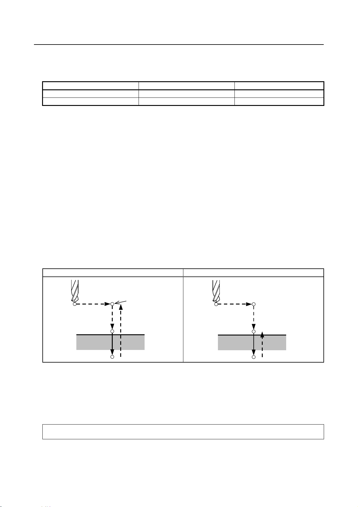
4.FUNCTIONS TO SIMPLIFY
B-64484EN-1/03 PROGRAMMING
Although canned cycles include tapping and boring cycles as well as drilling cycles, in this chapter, only
the term drilling will be used to refer to operations implemented with canned cycles.
Table 4.3 (b) Positioning axis and drilling axis
G code Positioning axis Drilling axis
G83, G84, G85 X axis, C axis Z axis
G87, G88, G89 Z axis, C axis X axis
G83 and G87, G84 and G88, and G85 and G89 have the same function respectively except for axes
specified as positioning axes and a drilling axis.
PROGRAMMING
- Drilling mode
G83 to G85/G87 to G89 are modal G codes and remain in effect until canceled. When in effect, the
current state is the drilling mode.
Once drilling data is specified in the drilling mode, the data is retained until modified or canceled.
Specify all necessary drilling data at the beginning of canned cycles; when canned cycles are being
performed, specify data modifications only.
The feedrate specified at F is retained also after the drilling cycle is canceled. When Q data is required, it
must be specified in each block. Once specified, the M code used for C-axis clamp/unclamp functions as
a modal code. It is canceled by specifying G80.
- Return point level
In G code system A, the tool returns to the initial level from the bottom of a hole. In G code system B or
C, specifying G98 returns the tool to the initial level from the bottom of a hole and specifying G99 returns
the tool to the point R level from the bottom of a hole.
The following illustrates how the tool moves when G98 or G99 is specified (Fig. 4.3 (b)). Generally, G99
is used for the first drilling operation and G98 is used for the last drilling operation.
The initial level does not change even when drilling is performed in the G99 mode.
G98 (Return to initial level) G99 (Return to point R level)
Initial level
Fig. 4.3 (b)
- Number of repeats
To repeat drilling for equally-spaced holes, specify the number of repeats in K_.
K is effective only within the block where it is specified.
Specify the first hole position in incremental programming.
If it is specified in absolute programming, drilling is repeated at the same position.
Number of repeats K The maximum command value = 9999
When K0 is specified, drilling data is just stored without drilling being performed.
Point R level
- 75 -
Page 90

4. FUNCTIONS TO SIMPLIFY
PROGRAMMING
PROGRAMMING B-64484EN-1/03
NOTE
For K, specify an integer of 0 or 1 to 9999.
- M code used for C-axis clamp/unclamp
When an M code specified in parameter No. 5110 for C-axis clamp/unclamp is coded in a program, the
following operations occur.
(1) The CNC issues the M code for C-axis clamp after the tool is positioned and while the tool is being
fed in rapid traverse to the point-R level.
(2) The CNC issues the M code for C-axis unclamp (the M code for C-axis clamp +1) after the tool
retracts to the point-R level.
(3) After the CNC issues the M code for C-axis unclamp, the tool dwells for the time specified in
parameter No. 5111.
- Cancel
To cancel a canned cycle, use G80 or a group 01 G code.
Group 01 G codes (Example)
G00 : Positioning (rapid traverse)
G01 : Linear interpolation
G02 : Circular interpolation (CW)
G03 : Circular interpolation (CCW)
- Symbols in figures
Subsequent subsections explain the individual canned cycles. Figures in these explanations use the
following symbols:
Positioning (rapid traverse G00)
Cutting feed (linear interpolation G01)
P1 Dwell specified in the program
P2 Dwell specified in parameter No.5111
Mα Issuing the M code for C-axis clamp
(The value of α is specified with parameter No. 5110.)
M (α + 1) Issuing the M code for C-axis unclamp
CAUTION
1 In each canned cycle, addresses R, Z, and X are handled as follows:
R_ : Always handled as a radius.
Z_ or X_ : Depends on diameter/radius programming.
2 For the B or C G-code system, G90 or G91 can be used to select an incremental
or absolute programming for hole position data (X, C or Z, C), the distance from
point R to the bottom of the hole (Z or X), and the distance from the initial level to
the point R level (R).
3 For canned cycles for drilling specified in the Series 15 format (by setting bit 1
(FCV) of parameter No. 0001 to 1 and bit 3 (F16) of parameter No. 5102 to 0),
incremental programming is used for point R data when bit 6 (RAB) of parameter
No. 5102 is set to 0.
When bit 6 (RAB) of parameter No. 5102 is set to 1, in G code system A,
absolute programming is used, and in G code system B or C, absolute or
incremental programming is used according to G90 or G91.
For canned cycles for drilling in the Series 16 format, incremental programming
is used for point R data.
- 76 -
Page 91

4.FUNCTIONS TO SIMPLIFY
α
B-64484EN-1/03 PROGRAMMING
PROGRAMMING
4.3.1 Front Drilling Cycle (G83)/Side Drilling Cycle (G87)
The peck drilling cycle or high-speed peck drilling cycle is used depending on the setting in RTR, bit 2 of
parameter No. 5101. If depth of cut for each drilling is not specified, the normal drilling cycle is used.
Without using the RTR parameter, the high-speed peck drilling cycle can be specified with G83.5 or
G87.5 and the peck drilling cycle can be specified with G83.6 or G87.6.
- High-speed peck drilling cycle (G83, G87) (bit 2 (RTR) of parameter No. 5101
=0)
This cycle performs high-speed peck drilling. The drill repeats the cycle of drilling at the cutting feedrate
and retracting the specified retraction distance intermittently to the bottom of a hole. The drill draws
cutting chips out of the hole when it retracts.
Format
G83 X(U)_ C(H)_ Z(W)_ R_ P_ Q_ F_ K_ M_ ;
or
G87 Z(W)_ C(H)_ X(U)_ R_ P_ Q_ F_ K_ M_ ;
X_ C_ or Z_ C_ : Hole position data
Z_ or X_ : The distance from point R to the bottom of the hole
R_ : The distance from the initial level to point R level
P_ : Dwell time at the bottom of a hole
Q_ : Depth of cut for each cutting feed
F_ : Cutting feedrate
K_ : Number of repeats (When it is needed)
M_ : M code for C-axis clamp (When it is needed.)
G83 or G87 (G98 mode) G83 or G87 (G99 mode)
M
α
Initial level
Point R
q
q
q
P1
M (α + 1), P2
d
d
Point Z
Mα : M code for C-axis clamp
M (α + 1) : M code for C-axis unclamp
P1 : Dwell specified in the program
P2 : Dwell specified in parameter No. 5111
d : Retraction distance specified in parameter No. 5114
Point R
q
q
q
M
M (α + 1), P2
Point R level
d
d
Point Z
P1
- 77 -
Page 92

4. FUNCTIONS TO SIMPLIFY
α
PROGRAMMING
PROGRAMMING B-64484EN-1/03
- Peck drilling cycle (G83, G87) (bit 2 (RTR) of parameter No. 5101 =1)
Format
G83 X(U)_ C(H)_ Z(W)_ R_ P_ Q_ F_ K_ M_ ;
or
G87 Z(W)_ C(H)_ X(U)_ R_ P_ Q_ F_ K_ M_ ;
X_ C_ or Z_ C_ : Hole position data
Z_ or X_ : The distance from point R to the bottom of the hole
R_ : The distance from the initial level to point R level
P_ : Dwell time at the bottom of a hole
Q_ : Depth of cut for each cutting feed
F_ : Cutting feedrate
K_ : Number of repeats (When it is needed.)
M_ : M code for C-axis clamp (When it is needed.)
G83 or G87 (G98 mode) G83 or G87 (G99 mode)
α
Initial level
M (α + 1), P2
P1
d
d
Point Z
M
M (α + 1), P2
Point R
q
q
q
Point R level
Point Z
P1
M
Point R
q
q
q
Mα : M code for C-axis clamp
M (α + 1) : M code for C-axis unclamp
P1 : Dwell specified in the program
P2 : Dwell specified in parameter No. 5111
d : Retraction distance specified in parameter No. 5115
Example
M51 ; Setting C-axis index mode ON
M3 S2000 ; Rotating the drill
G00 X50.0 C0.0 ; Positioning the drill along the X- and C-axes
G83 Z-40.0 R-5.0 Q5000 F5.0 M31 ; Drilling hole 1
C90.0 Q5000 M31 ; Drilling hole 2
C180.0 Q5000 M31 ; Drilling hole 3
C270.0 Q5000 M31 ; Drilling hole 4
G80 M05 ; Canceling the drilling cycle and stopping drill rotation
M50 ; Setting C-axis index mode off
NOTE
If the depth of cut for each cutting feed (Q) is not commanded, normal drilling is
performed. (See the description of the drilling cycle.)
d
d
- 78 -
Page 93
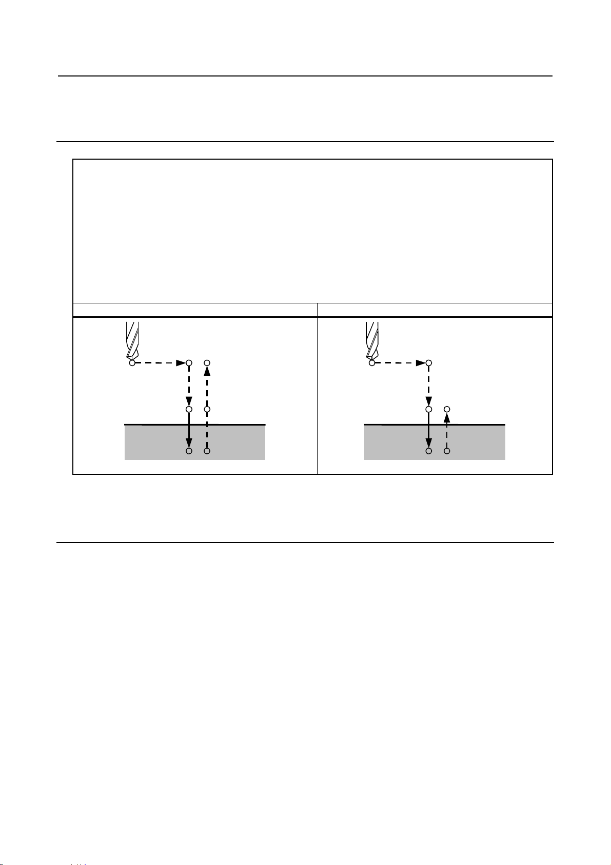
4.FUNCTIONS TO SIMPLIFY
α
B-64484EN-1/03 PROGRAMMING
PROGRAMMING
- Drilling cycle (G83 or G87)
If depth of cut (Q) is not specified for each drilling, the normal drilling cycle is used. The tool is then
retracted from the bottom of the hole in rapid traverse.
Format
G83 X(U)_ C(H)_ Z(W)_ R_ P_ F_ K_ M_ ;
or
G87 Z(W)_ C(H)_ X(U)_ R_ P_ F_ K_ M_ ;
X_ C_ or Z_ C_ : Hole position data
Z_ or X_ : The distance from point R to the bottom of the hole
R_ : The distance from the initial level to point R level
P_ : Dwell time at the bottom of a hole
F_ : Cutting feedrate
K_ : Number of repeats (When it is needed.)
M_ : M code for C-axis clamp (When it is needed.)
G83 or G87 (G98 mode) G83 or G87 (G99 mode)
Point R
M
α
P1
Initial level
Point R level
M (α + 1), P2
Point Z
Point R
M
M (α + 1), P2
P1
Mα : M code for C-axis clamp
M (α + 1) : M code for C-axis unclamp
P1 : Dwell specified in the program
P2 : Dwell specified in parameter No. 5111
Example
M51 ; Setting C-axis index mode ON
M3 S2000 ; Rotating the drill
G00 X50.0 C0.0 ; Positioning the drill along the X- and C-axes
G83 Z-40.0 R-5.0 P500 F5.0 M31 ; Drilling hole 1
C90.0 M31 ; Drilling hole 2
C180.0 M31 ; Drilling hole 3
C270.0 M31 ; Drilling hole 4
G80 M05 ; Canceling the drilling cycle and stopping drill rotation
M50 ; Setting C-axis index mode off
Point R level
Point Z
- 79 -
Page 94

4. FUNCTIONS TO SIMPLIFY
α
α
PROGRAMMING
PROGRAMMING B-64484EN-1/03
4.3.2 Front Tapping Cycle (G84) / Side Tapping Cycle (G88)
This cycle performs tapping.
In this tapping cycle, when the bottom of the hole has been reached, the spindle is rotated in the reverse
direction.
Format
G84 X(U)_ C(H)_ Z(W)_ R_ P_ F_ K_ M_ ;
or
G88 Z(W)_ C(H)_ X(U)_ R_ P_ F_ K_ M_ ;
X_ C_ or Z_ C_ : Hole position data
Z_ or X_ : The distance from point R to the bottom of the hole
R_ : The distance from the initial level to point R level
P_ : Dwell time at the bottom of a hole
F_ : Cutting feedrate
K_ : Number of repeats (When it is needed.)
M_ : M code for C-axis clamp (when it is needed.)
G84 or G88 (G98 mode) G84 or G88 (G99 mode)
Point R
M
P1
Initial level
Spindle CW
M (α + 1), P2
Point Z
Spindle CCW
Point R
P1
M
Spindle CW
M (α + 1), P2
Point R level
Point Z
Spindle CCW
Mα : M code for C-axis clamp
M (α + 1) : M code for C-axis unclamp
P1 : Dwell specified in the program
P2 : Dwell specified in parameter No. 5111
Explanation
Tapping is performed by rotating the spindle clockwise. When the bottom of the hole has been reached,
the spindle is rotated in the reverse direction for retraction. This operation creates threads.
Feedrate overrides are ignored during tapping. A feed hold does not stop the machine until the return
operation is completed.
NOTE
Bit 3 (M5T) of parameter No. 5105 specifies whether the spindle stop command
(M05) is issued before the direction in which the spindle rotates is specified with
M03 or M04. For details, refer to the operator's manual created by the machine
tool builder.
Example
M51 ; Setting C-axis index mode ON
M3 S2000 ; Rotating the drill
- 80 -
Page 95

4.FUNCTIONS TO SIMPLIFY
B-64484EN-1/03 PROGRAMMING
G00 X50.0 C0.0 ; Positioning the drill along the X- and C- axes
G84 Z-40.0 R-5.0 P500 F5.0 M31 ; Drilling hole 1
C90.0 M31 ; Drilling hole 2
C180.0 M31 ; Drilling hole 3
C270.0 M31 ; Drilling hole 4
G80 M05 ; Canceling the drilling cycle and stopping drill rotation
M50 ; Setting C-axis index mode off
PROGRAMMING
4.3.3 Front Boring Cycle (G85) / Side Boring Cycle (G89)
This cycle is used to bore a hole.
Format
G85 X(U)_ C(H)_ Z(W)_ R_ P_ F_ K_ M_ ;
or
G89 Z(W)_ C(H)_ X(U)_ R_ P_ F_ K_ M_ ;
X_ C_ or Z_ C_ : Hole position data
Z_ or X_ : The distance from point R to the bottom of the hole
R_ : The distance from the initial level to point R level
P_ : Dwell time at the bottom of a hole
F_ : Cutting feedrate
K_ : Number of repeats (When it is needed.)
M_ : M code for C-axis clamp (When it is needed.)
G85 or G89 (G98 mode) G85 or G89 (G99 mode)
M
Point R
α
P1
Initial level
M (α + 1), P2
Point Z
Point R
P1
M
α
Mα : M code for C-axis clamp
M (α + 1) : M code for C-axis unclamp
P1 : Dwell specified in the program
P2 : Dwell specified in parameter No. 5111
Explanation
After positioning, rapid traverse is performed to point R.
Drilling is performed from point R to point Z.
After the tool reaches point Z, it returns to point R at a feedrate twice the cutting feedrate.
Example
M51 ; Setting C-axis index mode ON
M3 S2000 ; Rotating the drill
G00 X50.0 C0.0 ; Positioning the drill along the X- and C-axes
G85 Z-40.0 R-5.0 P500 F5.0 M31 ; Drilling hole 1
C90.0 M31 ; Drilling hole 2
C180.0 M31 ; Drilling hole 3
C270.0 M31 ; Drilling hole 4
- 81 -
Point R level
M (α + 1), P2
Point Z
Page 96

4. FUNCTIONS TO SIMPLIFY
PROGRAMMING
PROGRAMMING B-64484EN-1/03
G80 M05 ; Canceling the drilling cycle and stopping drill rotation
M50 ; Setting C-axis index mode off
4.3.4 Canned Cycle for Drilling Cancel (G80)
G80 cancels canned cycle for drilling.
Format
G80 ;
Explanation
Canned cycle for drilling is canceled to perform normal operation. Point R and point Z are cleared.
Other drilling data is also canceled (cleared).
Example
M51 ; Setting C-axis index mode ON
M3 S2000 ; Rotating the drill
G00 X50.0 C0.0 ; Positioning the drill along the X- and C-axes.
G83 Z-40.0 R-5.0 P500 F5.0 M31 ; Drilling hole 1
C90.0 M31 ; Drilling hole 2
C180.0 M31 ; Drilling hole 3
C270.0 M31 ; Drilling hole 4
G80 M05 ; Canceling the drilling cycle and stopping drill rotation
M50 ; Setting C-axis index mode off
4.3.5 Canned Cycle for Drilling with M Code Output Improved
Overview
Up to two pairs of M codes used for C-axis clamp/unclamp in canned cycles for drilling can be set for
each path.
Details
Set the M codes for C-axis clamp/unclamp in the following parameters.
Bit 4 of parameter No. 5161=1
Pair 1 Pair 2
M code for clamp
M code for unclamp
When the M code for clamp set in parameter No. 5110 or 13544 (valid when bit 4 (CME) of parameter
No. 5161 is set to 1) is specified in the block for a canned cycle for drilling, the specified M code is
output before the tool is fed in rapid traverse to the point-R level after positioned. The M code for
unclamp paired with that specified M code is output after the tool retracts to the point-R level.
Example 1:
When bit 4 of parameter No. 5161 is set to 1, and 68, 78, 168, and 178 are specified in parameters
Nos. 5110, 13543, 13544, 13545, respectively, the following M codes are output.
Command Clamp Unclamp
G83X_C_...M68 M68 M78
G83X_C_...M168 M168 M178
No.5110 No.13544 No.5110
No.13543 No.13545 (Setting in parameter No. 5110 + 1)
- 82 -
Bit 4 of parameter No. 5161=0
Page 97

4.FUNCTIONS TO SIMPLIFY
B-64484EN-1/03 PROGRAMMING
Example 2:
When bit 4 of parameter No. 5161 is set to 0, and 68 is specified in parameter No. 5110, respectively,
the following M codes are output.
Command Clamp Unclamp
G83X_C_...M68 M68 M69
PROGRAMMING
NOTE
1 Both the M codes for clamp and unclamp are set to 0, the setting of the pair is
invalid.
2 If the same M code for clamp is set for pairs 1 and 2, the setting for pair 1 that is
specified in parameter No. 13543 is used as the M code for unclamp.
4.3.6 Precautions to be Taken by Operator
- Reset and emergency stop
Even when the controller is stopped by resetting or emergency stop in the course of drilling cycle, the
drilling mode and drilling data are saved; with this mind, therefore, restart operation.
- Single block
When drilling cycle is performed with a single block, the operation stops at the end points of operations 1,
2, 6 in Fig. 4.3 (a).
Consequently, it follows that operation is started up 3 times to drill one hole. The operation stops at the
end points of operations 1, 2 with the feed hold lamp ON. If there is a remaining repetitive count at the
end of operation 6, the operation is stopped by feed hold. If there is no remaining repetitive count, the
operation is stopped in the single block stop state.
- Feed hold
When "Feed Hold" is applied between operations 3 and 5 by G84/G88, the feed hold lamp lights up
immediately if the feed hold is applied again to operation 6.
- Override
During operation with G84 and G88, the feedrate override is 100%.
4.4 IN-POSITION CHECK SWITCHING FOR DRILLING
CANNED CYCLE
Overview
This function enables dedicated in-position widths to be used for drilling canned cycle.
Up to four different dedicated in-position widths are available, one for hole bottoms and three for other
than hole bottoms. Using a little large in-position width for operations at locations where no nigh
precision is required makes drilling canned cycle faster.
Explanation
Setting bit 4 (ICS) of parameter No. 5107 to 1 enables dedicated in-position widths to be used for drilling
canned cycle. Up to four different dedicated in-position widths are available, one for hole bottoms and
three for other than hole bottoms.
In conventional drilling canned cycle, the same operation is performed for both in-position checks
between cycles for locations where no very high precision is required (A in Fig. 4.4 (a)) and in-position
checks between cycles for hole bottoms where a high precision is required (B in Fig. 4.4 (a)) because the
same in-position width is used for all cycles.
- 83 -
Page 98

4. FUNCTIONS TO SIMPLIFY
PROGRAMMING
PROGRAMMING B-64484EN-1/03
Using this function makes it possible to reduce the time needed to get in an in-position state (to reduce the
necessary cycle time) by setting a small in-position width for hole bottoms so as to assure a high precision
while setting a little large in-position width for other than hole bottoms.
Fig. 4.4 (a) Example of a peck drilling cycle (G83)
- Parameters related to in-position wi dths
This function uses the following in-position widths.
In-position width for other than hole bottoms (regular) (parameter No. 5184)
In-position width for other than hole bottoms (for retraction in peck drilling cycle) (parameter No.
5185)
In-position width for other than hole bottoms (for shift in boring cycles (G76 and G87) (parameter
No. 5186)
In-position width for hole bottoms (parameter No. 5187)
- Supported drilling canned cycle
The following table lists the drilling canned cycle for which this function is usable.
T
Table 4.4 (a) Drilling canned cycle for which this function is usable (lathe system)
G code Use
G83 High-speed peck drilling cycle
G83.5 Front high-speed peck drilling cycle
G83.6 Front peck drilling cycle
G84 Front tapping cycle
G85 Front boring cycle
G87 Side drilling cycle
G87.5 Side high-speed peck drilling cycle
G87.6 Side peck drilling cycle
G88 Side tapping cycle
G89 Side boring cycle
- 84 -
Page 99
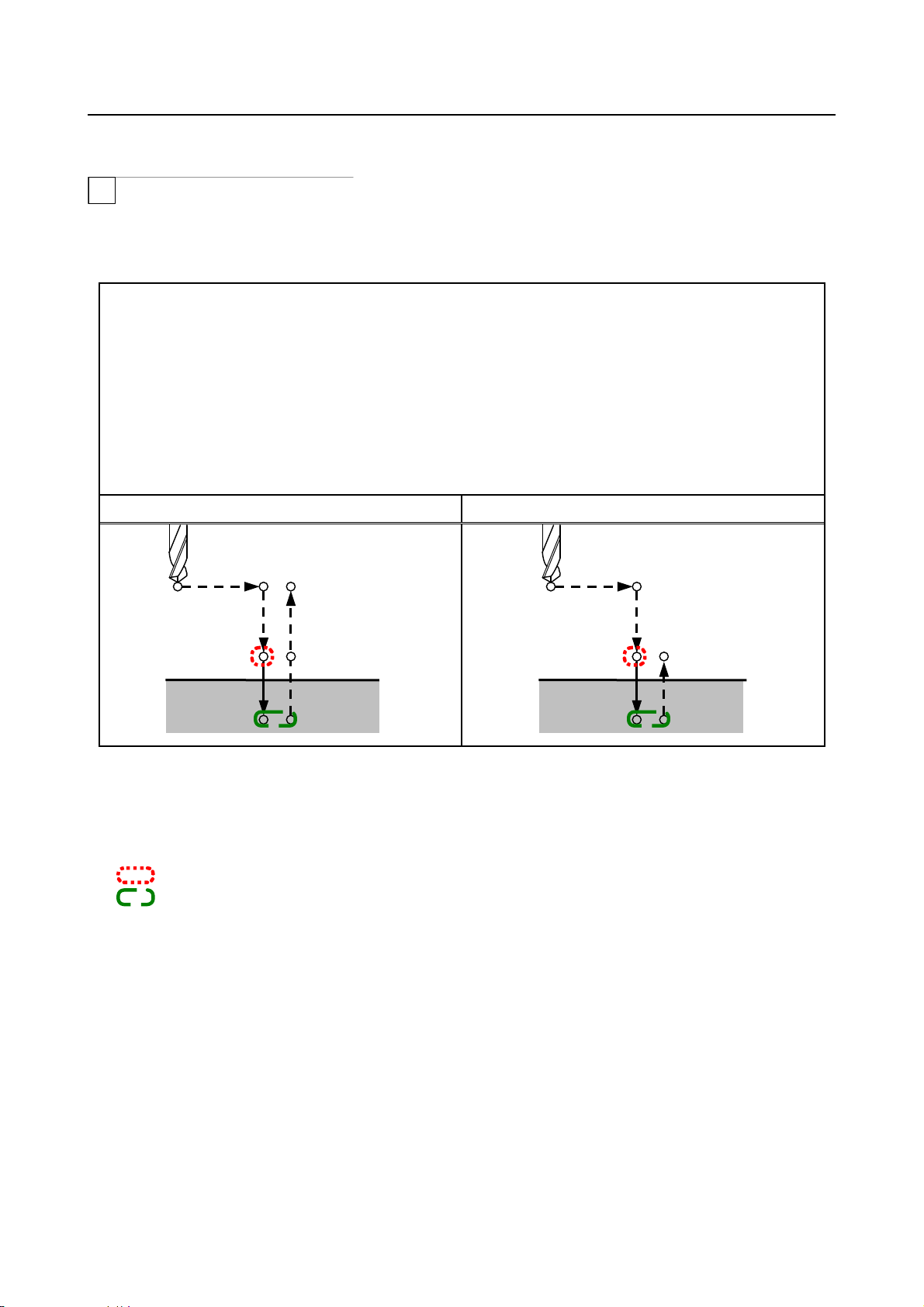
4.FUNCTIONS TO SIMPLIFY
α
B-64484EN-1/03 PROGRAMMING
PROGRAMMING
- Front drilling cycle (G83)/side drilling cycle (G87)
T
Shown below are the points where a dedicated effective area (for in-position check) is applied in front
drilling cycle and side drilling cycle.
If no Q (depth of cut for each cutting feed) is specified in a drilling cycle (G83 or G87), an ordinary
drilling cycle is assumed.
G83 X(U)_ C(H)_ Z(W)_ R_ P_ F_ K_ M_ ;
or
G87 Z(W)_ C(H)_ X(U)_ R_ P_ F_ K_ M_ ;
X_ C_ or Z_ C_ : Hole position data
Z_ or X_ : The distance from point R to the bottom of the hole
R_ : The distance from the initial level to point R level
P_ : Dwell time at the bottom of a hole
F_ : Cutting feedrate
K_ : Number of repeats (When it is needed)
M_ : M code for C-axis clamp (When it is needed.)
G83 or G87 (G98 mode) G83 or G87 (G99 mode)
Mα
Initial level
Point R
Point R level
M(α+1),P2
Point Z
P1
Mα : M code for C-axis clamp
M(α+1) : M code for C-axis unclamp
P1 : Dwell specified in the program
P2 : Dwell specified in parameter No. 5111
In-position width for other than hole bottoms (regular)
In-position width for hole bottoms
Point R
M
P1
Point R level
M(α+1),P2
Point Z
- 85 -
Page 100

4. FUNCTIONS TO SIMPLIFY
PROGRAMMING
PROGRAMMING B-64484EN-1/03
- Front high-speed peck drilling cycle (G83, G83.5) / Side high-speed peck
drilling cycle (G87, G87.5)
T
Shown below are the points where a dedicated effective area (for in-position check) is applied in front
high-speed peck drilling cycle and side high-speed peck drilling cycle. In high-speed peck drilling cycles
(G83 and G87) (bit 2 (RTR) of parameter No. 5101 = 0), G83.5 and G87.5 can also be used to perform
high-speed peck drilling regardless of the setting of the parameter RTR.
G83 X(U)_ C(H)_ Z(W)_ R_ P_ Q_ F_ K_ M_ ;
or
G87 Z(W)_ C(H)_ X(U)_ R_ P_ Q_ F_ K_ M_ ;
X_ C_ or Z_ C_ : Hole position data
Z_ or X_ : The distance from point R to the bottom of the hole
R_ : The distance from the initial level to point R level
P_ : Dwell time at the bottom of a hole
Q_ : Depth of cut for each cutting feed
F_ : Cutting feedrate
K_ : Number of repeats (When it is needed)
M_ : M code for C-axis clamp (When it is needed.)
G83 or G87 (G98 mode) G83 or G87 (G99 mode)
Initial level
Point R
Q
Q
Q
Mα
P1
M(α+1),P2
d
d
Point Z
Point R
Mα
M(α+1),P2
Point R level
Q
Q
Q
P1
d
d
Point Z
Mα : M code for C-axis clamp
M(α+1) : M code for C-axis unclamp
P1 : Dwell specified in the program
P2 : Dwell specified in parameter No. 5111
d : Retraction distance specified in parameter No. 5114
In-position width for other than hole bottoms (regular)
In-position width for other than hole bottoms (for retraction in peck drilling cycle)
In-position width for hole bottoms
- 86 -
 Loading...