

Page 1

FANUC Series 30*-MODEL B
FANUC Series 31*-MODEL B
FANUC Series 32*-MODEL B
CONNECTION MANUAL (HARDWARE)
B-64483EN/01
Page 2

• No part of this manual may be reproduced in any form.
• All specifications and designs are subject to change without notice.
The products in this manual are controlled based on Japan’s “Foreign Exchange and
Foreign Trade Law”. The export of Series 30i-B, Series 31i-B5 from Japan is subject to an
export license by the government of Japan. Other models in this manual may also be
subject to export controls.
Further, re-export to another country may be subject to the license of the government of
the country from where the product is re-exported. Furthermore, the product may also be
controlled by re-export regulations of the United States government.
Should you wish to export or re-export these products, please contact FANUC for advice.
The products in this manual are manufactured under strict quality control. However, when
using any of the products in a facility in which a serious accident or loss is predicted due to
a failure of the product, install a safety device.
In this manual we have tried as much as possible to describe all the various matters.
However, we cannot describe all the matters which must not be done, or which cannot be
done, because there are so many possibilities.
Therefore, matters which are not especially described as possible in this manual should be
regarded as ”impossible”.
This manual contains the program names or device names of other companies, some of
which are registered trademarks of respective owners. However, these names are not
followed by ® or ™ in the main body.
Page 3
B-64483EN/01 SAFETY PRECAUTIONS
SAFETY PRECAUTIONS
Described below are the safety precautions regarding the control units and those peripheral units
explained herein. The safety precautions must be observed in order to use these units safely.
Because exchanging, as well as performing daily maintenance operations on, the control units and those
peripheral units explained herein may incur diverse dangers, you cannot be involved in such work unless
you have been sufficiently trained for safety.
Some safety precautions may not apply to your control units or peripheral units explained herein because
the units have no corresponding function. If this is the case, skip reading those precautions.
As for safety precautions regarding machine tools, refer to the respective machine manuals provided by
the machine tool builders.
Before starting to operate machines for check purposes, be sure to read the manuals provided by the
machine tool builders and FANUC and sufficiently understand their descriptions.
Contents
DEFINITION OF WARNING, CAUTION, AND NOTE.........................................................................s-1
WARNINGS AND CAUTIONS REGARDING MOUNTING, WIRING, AND EXCHANGING..........s-2
WARNINGS AND CAUTIONS REGARDING DESIGNING.................................................................s-4
WARNINGS, CAUTIONS, AND NOTES REGARDING DAILY MAINTENANCE............................s-5
DEFINITION OF WARNING, CAUTION, AND NOTE
This manual includes safety precautions for protecting the user and preventing damage to the machine.
Precautions are classified into Warning and Caution according to their bearing on safety. Also,
supplementary information is described as a Note. Read the Warning, Caution, and Note thoroughly
before attempting to use the machine.
WARNING
Applied when there is a danger of the user being injured or when there is a
danger of both the user being injured and the equipment being damaged if the
approved procedure is not observed.
CAUTION
Applied when there is a danger of the equipment being damaged, if the
approved procedure is not observed.
NOTE
The Note is used to indicate supplementary information other than Warning and
Caution.
• Read this manual carefully, and store it in a safe place.
s-1
Page 4

SAFETY PRECAUTIONS B-64483EN/01
WARNINGS AND CAUTIONS REGARDING MOUNTING, WIRING, AND EXCHANGING
WARNING
1 Before starting mounting, wiring, and exchanging, be sure to shut off externally
supplied power. Otherwise, electrical shocks, breakdown, and blowout may
occur.
If a control unit is turned off but other units are not, it is likely that power may be
supplied to servo units, resulting in the units being damaged and workers getting
an electrical shock when the units are exchanged.
2 Voltage lingers in servo and spindle amplifiers for a while even after power has
been turned off, resulting in workers possibly getting an electrical shock when
the workers touch them. Before starting to exchange these amplifiers, wait for 20
minutes after power has been turned off.
3 Be sure to ground your control units and peripheral units in accordance with your
national grounding standards (protective grounding class C or stricter).
Otherwise, electrical shocks, breakdown, and blowout may occur.
4 In order to prevent damage that may be caused by static electricity, wear a
grounding wrist strap or take a similar protective measure before starting to
touch a printed-circuit board or unit or attach a cable.
Static electricity from human bodies can damage electrical circuits.
5 In unit replacement, specify the same settings and parameters in the newly
installed unit as those for the one removed. (For details, refer to the respective
manuals for the units.)
Operating the newly installed unit with incorrect settings or parameters will cause
the machine to behave unexpectedly, possibly leading to a damaged workpiece
or machine or injury.
6 If you notice an apparent hardware fault, such as abnormal noise, abnormal
odor, smoke, ignition, or abnormal heat, in the hardware while power is being
supplied to it, shut it off at once. These faults can cause fire, breakdown,
blowout, and malfunction.
7 The radiating fins of control units, servo amplifiers, spindle amplifiers, and other
devices can remain very hot for a while after power has been turned off, making
you get burned if you touch them. Before starting to work on them, wait and
make sure they are cool.
8 When exchanging heavy stuff, you should do so together with two or more
people.
If you try to exchange heavy stuff all by yourself, you may drop it and get hurt.
9 Wiring work in the control units and peripheral units must be done only after they
have been installed. Otherwise, electrical shocks can occur.
10 Be careful not to damage cables. Otherwise, electrical shocks can occur.
11 When working, wear suitable clothes with safety taken into account. Otherwise,
injury and electrical shocks can occur.
12 Do not work with your hands wet. Otherwise, electrical shocks and damage to
electrical circuits can occur.
s-2
Page 5

B-64483EN/01 SAFETY PRECAUTIONS
CAUTION
Failing to observe any caution stated below can lead to fire, breakdown, blowout,
and malfunction.
1 Do not attach the units directly to any flammable object or install the units near
any flammable object.
2 Do not allow any foreign matter (such as a screw, metal chip, or coolant) to get
in the units.
3 Handle the units and printed-circuit boards gently because they are precision
devices. Be careful not to drop them or give a high impact to them.
4 Lay signal wires away from power wires as stated in this manual.
5 When fastening each unit or wire, be sure to observe the screw tightening torque
specified for them. If screws are tightened too weakly or too strongly, it is likely
that the unit may drop, break, or malfunction, or the wire may be short-circuited.
Do not forget to tighten all necessary screw.
6 Do not block any cooling fan air inlet or outlet. For units having no cooling fan,
allow space for natural convection cooling above and below them.
7 Be careful not to make an incorrect wiring or connection. Be sure to attach wires
and cables to their respective corresponding terminals and connectors.
8 Confirm equipment’s electrical rating stated herein. Do not apply any unspecified
voltage to the equipment.
9 Do not confuse voltage polarity. Carefully confirm the arrangement of connector
pins.
10 When making a cable assembly, press-mount, crimp, or solder the wires, using
the tool specified by the cable manufacturer.
11 Use printed-circuit boards and peripheral units that match your control unit.
12 When mounting the units, pay attention to their mass.
13 When detaching a cable from a unit, hold the connector rather than the cable.
When attaching a cable, be sure to fit its connector to the connector pins
securely. For connectors having a lock mechanism, be sure to lock them
securely.
14 As for the shielding wires of the cables specified herein, securely ground them,
using, for example, cable clamps.
15 Always use wires whose length, diameter, heat resistance, and flex resistance
match their use.
s-3
Page 6

SAFETY PRECAUTIONS B-64483EN/01
WARNINGS AND CAUTIONS REGARDING DESIGNING
WARNING
1 When designing, be sure to observe all rules stated in this document and any
related manuals. Otherwise, it is likely that failure and malfunction may occur.
2 Failures in the control units and I/O units as well as input power abnormality and
communication failures can hamper the normal operation of these I/O units.
Design each I/O unit in such a way that the machine can operate safely, for
example, by providing an external safety circuit to the I/O unit so that no accident
will occur even if the I/O unit fails to operate normally.
The DO function of each I/O unit has been designed in such a way that, if a
system alarm is issued in the control unit that controls the I/O unit or the power
of the control unit or the I/O unit is turned off, the DO function of all the I/O units
is turned off. However, it is not guaranteed that the DO function is surely turned
off. So, it is requested that, if a signal regarding safety is involved, a safety circuit
external to each I/O unit must be configured. Using the dual check safety
function makes it possible to detect a single fault in a portion related to safety.
For details of the dual check safety function, refer to the FANUC Series
30i/31i/32i-MODEL B Dual Check Safety Connection Manual (B-64483EN-2).
3 Coolants containing sulfur or chlorine at a high activation level, oil-free coolants
called synthetic, and water-soluble coolants at a high alkali level, in particular,
can largely affect the CNC and peripheral units. Please note that, even if
consideration is taken to protect them from direct exposure to these coolants,
the following trouble is likely to occur.
Coolants containing sulfur or chlorine at a high activation level
•
Some coolants containing sulfur or chlorine are at an extremely high activity
level. If such a coolant adheres to the CNC or peripheral units, it reacts
chemically with a material, such as resin, of equipment, possibly leading to
corrosion or deterioration. If it gets in the CNC or peripheral units, it corrodes
metals, such as copper and silver, used as component materials, possibly
leading to a defective component.
Synthetic-type coolants having a high permeability
•
Some synthetic-type coolants whose lubricating component is, for example,
PAG (polyalkylene glycol) have an extremely high permeability. If such a
coolant is used even in equipment having a high closeness, it can readily flow
into the CNC or peripheral units through, for example, gaskets. It is likely that,
if the coolant gets in the CNC or a peripheral unit, it may deteriorate the
insulation and damage the components.
Water-soluble coolants at a high alkali level
•
Some coolants whose pH is increased using alkanolamine are so strong
alkali that its standard dilution will lead to pH10 or higher. If such a coolant
spatters over the surface of the CNC or peripheral unit, it reacts chemically
with a material, such as resin, possibly leading to corrosion or deterioration.
CAUTION
Install each control unit, display unit, MDI unit, and machine operator panel in
such a place that neither cutting chip nor coolant will spatter to them. Otherwise,
damage or malfunction may occur.
s-4
Page 7

B-64483EN/01 SAFETY PRECAUTIONS
WARNINGS, CAUTIONS, AND NOTES REGARDING DAILY MAINTENANCE
WARNING
Battery replacement
Do not replace batteries unless you have been well informed of maintenance
work and safety.
When opening the cabinet and replacing batteries, be careful not to touch any
high-voltage circuit (marked with
prevention cover).
When the electric shock prevention cover has been removed, you will get an
electric shock if you touch any high-voltage circuit.
WARNING
Fuse replacement
Before replacing a blown fuse, it is necessary to remove the cause of the blown
fuse.
So, do not replace fuses unless you have been well informed of maintenance
work and safety.
When opening the cabinet and replacing fuses, be careful not to touch any
high-voltage circuit (marked with
prevention cover).
When the electric shock prevention cover has been removed, you will get an
electric shock if you touch any high-voltage circuit.
CAUTION
Handle the batteries gently. Do not drop them or give a strong impact to them.
NOTE
Each control unit uses batteries, because it must hold data, such as programs,
offset values, and parameters even when AC power for it is off.
Back up the data (programs, offset values, and parameters) regularly.
If the battery voltage becomes low, a low battery voltage alarm is displayed on
the machine operator’s panel or screen.
Once the battery voltage alarm has been displayed, replace the batteries within
one week. Otherwise, the memory contents may be lost.
For the battery replacement procedure, see Section 4.4, “Batteries”. Recollect or
discard old batteries in the way your local autonomous community specifies.
and covered with an electric shock
and covered with an electric shock
s-5
Page 8

Page 9
B-64483EN/01 PREFACE
PREFACE
This manual describes the information, that is, electrical and structural specifications, needed in
connecting machine tools to the control and peripheral units stated below. The manual covers the range
shown on the total connection diagrams mentioned in Chapter 2. The manual briefly describes the units
that are used in common with the FANUC control units, such as FANUC I/O units, FANUC PANEL
and servo motors. It also gives supplementary information for use of these units with the control units.
For detailed specifications, refer to the manuals of these components.
For options not covered in this manual, also refer to the manuals of these components.
Applicable models
The models covered by this manual, and their abbreviations are :
Model name Abbreviation
FANUC Series 30i–B 30i–B Series 30i
FANUC Series 31i–B5 31i–B5
FANUC Series 31i–B 31i–B
FANUC Series 32i–B 32i–B Series 32i
Series 31i
Organization of this manuals
This manual consists of chapters 1 to 13 and appendixes at the end of the book.
Chapter and title Contents
Chapter 1
CONFIGURATION
Chapter 2
TOTAL CONNECTION
DAIGRAMS
Chapter 3
INSTALLATION
Chapter 4
POWER SUPPLAY
CONNECTION
Chapter 5
CONNECTION TO CNC
PERIOHERALS
Chapter 6
SERVO AND SPINDLE
INTERFACES
Chapter 7
CONNECTION TO FANUC I/O
Link i AND FANUC I/O Link
Chapter 8
UNITS CONNECTED TO FANUC
I/O Link i AND FANUC I/O Link
Chapter 9
STOP AND EMERGENCY STOP
Chapter 10
CONNECTION TO OTHER
NETWORKS
Chapter 11
CONNECTION FOR PERSONAL
COMPUTER FUNCTION WITH
Windows® CE
Provides general information related to the connection of the 30i–B series, as
well as an introduction to detailed information.
Describes how to connect peripheral units to the 30i–B series.
Describes the installation requirements for using the 30i–B series.
Describes how to make connections related to the power supply of the 30i–B
series.
Describes how to connect the peripheral devices to the 30i–B series.
Describes how to connect the 30i–B series to servo or spindle amplifiers.
Also explains how to connect separate detector interface units.
Describes how to connect machine interface I/O units using the FANUC I/O
Link i and FANUC I/O Link.
Describes major units that correspond to the FANUC I/O Link i and FANUC
I/O Link.
Describes how to handle the emergency stop signal.
A lot of important information regarding safety is included. Be sure to read It.
Describes how to connect the 30i–B series to networks.
Describes connection for the personal computer function with Windows® CE.
i,
p-1
Page 10

PREFACE B-64483EN/01
Chapter and title Contents
Chapter 12
CONNECTION WITH THE
FANUC PANEL i AND
COMMERCIAL PERSONAL
COMPUTERS
Chapter 13
PANEL i
APPENDIX A) OUTLINE DRAWINGS OF UNITS AND CONNECTORS
Some 30i–B series models have additional personal computer function with Windows® CE. Items
specific to these models are explained in Chapter 11. Please check them before common items.
Describes how to connect the 30i series to the FANUC PANEL i or a
commercial personal computer, using the high-speed serial bus (HSSB) or
Ethernet.
Describes how to connect a PANEL i to the 30i series.
B) 20-PIN INTERFACE CONNECTORS AND CABLES
C) CONNECTION CABLE (SUPPLIED FROM US)
D) OPTICAL FIBER CABLE
E) MEMORY CARD INTERFACE
p-2
Page 11
B-64483EN/01 PREFACE
Related manuals of Series 30i/31i/32i-MODEL B
The following table lists the manuals related to Series 30i-B, Series 31i-B, Series 32i-B. This manual is
indicated by an asterisk(*).
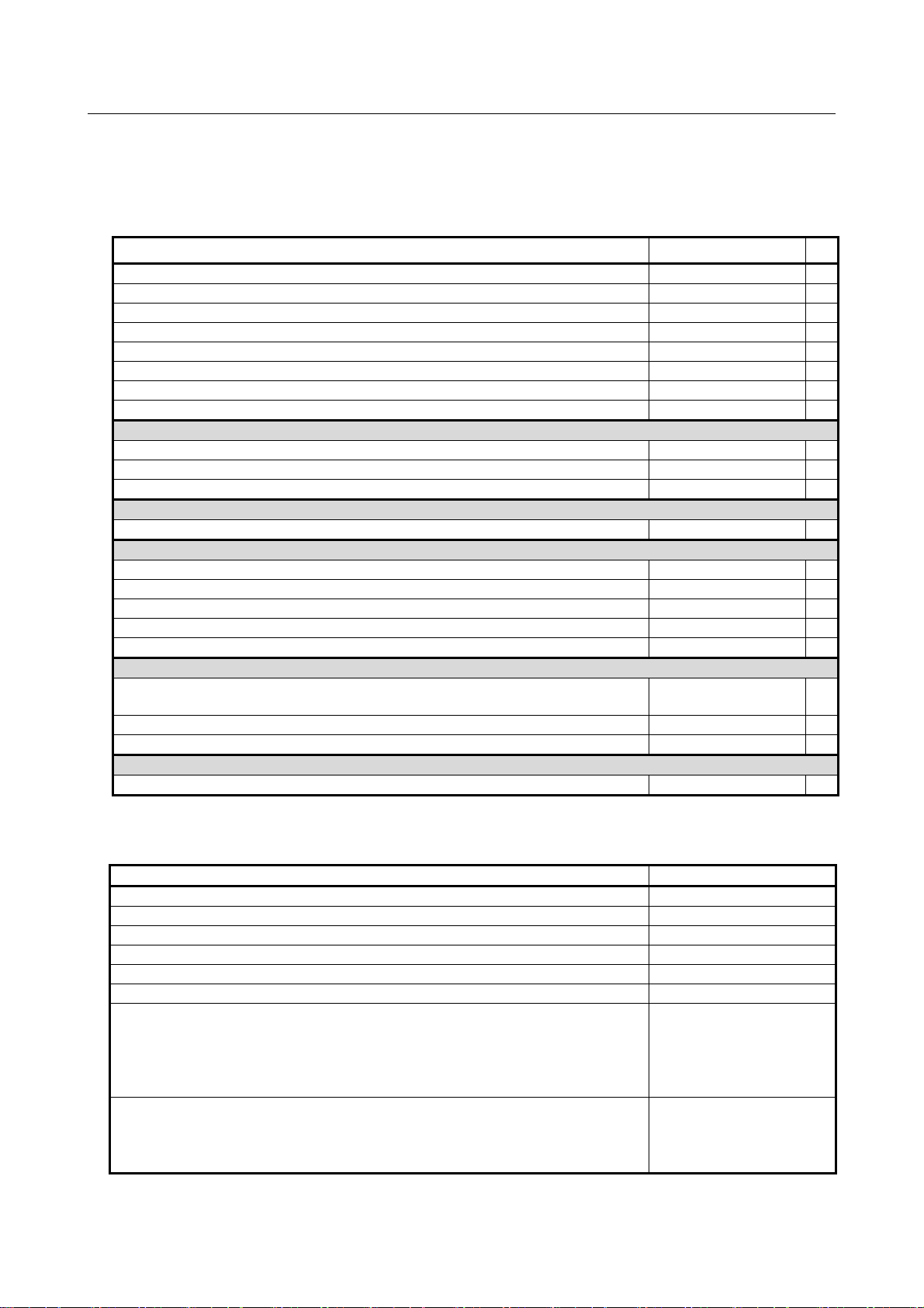
Table 1 Related manuals
Manual name Specification number
DESCRIPTIONS B-64482EN
CONNECTION MANUAL (HARDWARE) B-64483EN *
CONNECTION MANUAL (FUNCTION) B-64483EN-1
OPERATOR’S MANUAL (Common to Lathe System/Machining Center System) B-64484EN
OPERATOR’S MANUAL (For Lathe System) B-64484EN-1
OPERATOR’S MANUAL (For Machining Center System) B-64484EN-2
MAINTENANCE MANUAL B-64485EN
PARAMETER MANUAL B-64490EN
Programming
Macro Executor PROGRAMMING MANUAL B-63943EN-2
Macro Compiler PROGRAMMING MANUAL B-66263EN
C Language Executor PROGRAMMING MANUAL B-63943EN-3
PMC
PMC PROGRAMMING MANUAL B-64513EN
Network
PROFIBUS-DP Board CONNECTION MANUAL B-63993EN
Fast Ethernet / Fast Data Server OPERATOR’S MANUAL B-64014EN
DeviceNet Board CONNECTION MANUAL B-64043EN
FL-net Board CONNECTION MANUAL B-64163EN
CC-Link Board CONNECTION MANUAL B-64463EN
Operation guidance function
MANUAL GUIDE i
(Common to Lathe System/Machining Center System) OPERATOR’S MANUAL
MANUAL GUIDE i (For Machining Center System) OPERATOR’S MANUAL
MANUAL GUIDE i (Set-up Guidance Functions) OPERATOR’S MANUAL
Dual Check Safety
Dual Check Safety CONNECTION MANUAL B-64483EN-2
B-63874EN
B-63874EN-2
B-63874EN-1
Related manuals of SERVO MOTOR αis/αi/βis/βi series
The following table lists the manuals related to SERVO MOTOR αis/αi/βis/βi series
Manual name Specification number
FANUC AC SERVO MOTOR αi series DESCRIPTIONS
FANUC AC SPINDLE MOTOR αi series DESCRIPTIONS
FANUC AC SERVO MOTOR βi series DESCRIPTIONS
FANUC AC SPINDLE MOTOR βi series DESCRIPTIONS
FANUC SERVO AMPLIFIER αi series DESCRIPTIONS
FANUC SERVO AMPLIFIER βi series DESCRIPTIONS
FANUC SERVO MOTOR αis series
FANUC SERVO MOTOR αi series
FANUC AC SPINDLE MOTOR αi series
FANUC SERVO AMPLIFIER αi series
MAINTENANCE MANUAL
FANUC SERVO MOTOR βis series
FANUC AC SPINDLE MOTOR βi series
FANUC SERVO AMPLIFIER βi series
MAINTENANCE MANUAL
B-65262EN
B-65272EN
B-65302EN
B-65312EN
B-65282EN
B-65322EN
B-65285EN
B-65325EN
p-3
Page 12

PREFACE B-64483EN/01
Manual name Specification number
FANUC AC SERVO MOTOR αi series
FANUC AC SERVO MOTOR βi series
FANUC LINEAR MOTOR LiS series
FANUC SYNCHRONOUS BUILT-IN SERVO MOTOR DiS series
PARAMETER MANUAL
FANUC AC SPINDLE MOTOR αi series
FANUC AC SPINDLE MOTOR βi series
BUILT-IN SPINDLE MOTOR Bi series
PARAMETER MANUAL
B-65270EN
B-65280EN
Related manuals of FANUC PANEL i
The following table lists the manuals related to FANUC PANEL i.
Manual name Specification number
FANUC PANEL i CONNECTION AND MAINTENANCE MANUAL
B-64223EN
Related manuals of FANUC I/O Unit
The following table lists the manuals related to FANUC I/O Unit.
Manual name Specification number
FANUC I/O Unit-MODEL A CONNECTION AND MAINTENANCE MANUAL B-61813E
FANUC I/O Unit-MODEL B CONNECTION AND MAINTENANCE MANUAL B-62163E
Handy Machine Operator’s Panel CONNECTION MANUAL B-63753EN
Training
• FANUC runs FANUC Training Center to train those who will be involved in the connection,
maintenance, and operation of FANUC products. It is recommended to attend the class so you will
be able to use the products effectively.
Visit the following web site for detailed descriptions of its curriculum.
http://www.fanuc.co.jp/
p-4
Page 13

B-64483EN/01 TABLE OF CONTENTS
TABLE OF CONTENTS
SAFETY PRECAUTIONS............................................................................s-1
DEFINITION OF WARNING, CAUTION, AND NOTE.............................................s-1
WARNINGS AND CAUTIONS REGARDING MOUNTING, WIRING, AND
EXCHANGING............................................................................................s-2
WARNINGS AND CAUTIONS REGARDING DESIGNING.....................................s-4
WARNINGS, CAUTIONS, AND NOTES REGARDING DAILY MAINTENANCE ....s-5
PREFACE....................................................................................................p-1
1 CONFIGURATION ..................................................................................1
1.1 CONTROL UNIT CONFIGURATION AND COMPONENT NAMES..............1
1.1.1 Configurations of LCD-mounted Type Control Units .............................................1
1.1.2 Configurations of Stand-alone Type Control Units..................................................5
1.1.3 Configurations of Optional Boards ........................................................................10
1.2 HARDWARE OVERVIEW............................................................................11
1.2.1 LCD-mounted Type Control Unit Overview .........................................................11
1.2.2 Stand-alone Type Control Unit Overview..............................................................12
2 TOTAL CONNECTION DIAGRAMS.....................................................13
3 INSTALLATION ....................................................................................17
3.1 ENVIRONMENTAL REQUIREMENTS OUTSIDE THE CABINET...............17
3.1.1 Environmental Conditions outside the Cabinet......................................................17
3.1.2 Installation Conditions of the Control Unit............................................................17
3.2 CAUTIONS REGARDING THE INSTALLATION DESIGN OF MACHINE
TOOL POWER MAGNETICS CABINETS ...................................................18
3.3 THERMAL DESIGN OF THE MACHINE TOOL MAGNETIC CABINET......20
3.3.1 Temperature Rise within the Machine Tool Magnetic Cabinet..............................20
3.3.2 Heat Output of Each Unit.......................................................................................20
3.3.3 Thermal Design of Operator's Panel.......................................................................21
3.4 COUNTERMEASURES AGAINST NOISE AND GROUNDING ..................23
3.4.1 Grounding as Noise Suppression Measures ...........................................................24
3.4.1.1 Grounding methods ...........................................................................................24
3.4.1.2 Cabinet............................................................................................................... 25
3.4.2 Protective Ground (Grounding for Protection against Indirect Contact) ...............28
3.4.3 Connecting the Ground Terminal of the Control Unit ...........................................29
3.4.4 Separating Signal Lines..........................................................................................32
3.4.5 Noise Suppressor....................................................................................................33
3.4.6 Cable Clamp and Shield Processing.......................................................................34
3.4.7 Lightning Surge Absorber Installation...................................................................37
3.5 INSTALLING THE CONTROL UNIT............................................................38
3.5.1 Installing the LCD-mounted Type Control Unit....................................................38
3.5.2 Installing the Stand-alone Type Control Unit ........................................................39
3.6 TIGHTENING TORQUE FOR FASTENING UNITS AND GROUND
TERMINALS................................................................................................40
3.7 DUSTPROOF MEASURES FOR CABINETS AND PENDANT BOXES......40
3.8 LCD PROTECTION COVER .......................................................................43
3.9 ATTACHING SCREW CAPS.......................................................................43
c-1
Page 14

TABLE OF CONTENTS B-64483EN/01
4 POWER SUPPLY CONNECTION.........................................................44
4.1 24 VDC POWER (INSULATION AC/DC CONVERTOR).............................44
4.1.1 Connecting 24 VDC Power....................................................................................44
4.1.2 24 VDC Power Supply Specification.....................................................................46
4.1.3 Power Capacity of 24 VDC Power Supplies..........................................................48
4.2 TURNING ON AND OFF THE POWER TO THE CONTROL UNIT.............50
4.2.1 Power-on Sequence................................................................................................50
4.2.2 Power-off Sequence ...............................................................................................51
4.3 CABLE FOR POWER SUPPLY TO CONTROL UNIT.................................53
4.4 BATTERIES.................................................................................................53
4.4.1 Battery for Memory Backup in the Control Unit (3 VDC) ....................................54
4.4.1.1 Replacing the lithium battery............................................................................. 54
4.4.1.2 Replacing commercially available alkaline dry cells (size D)...........................56
4.4.2 Battery for Separate Absolute Pulsecoders (6VDC) ..............................................58
4.4.3 Battery for Absolute Pulse Coder Built into the Motor (6VDC)............................59
5 CONNECTION TO CNC PERIPHERALS .............................................60
5.1 CONNECTION BETWEEN THE LCD-MOUNTED TYPE CONTROL UNIT
AND MDI UNIT............................................................................................60
5.1.1 Connection Diagram...............................................................................................60
5.1.2 Connection with the MDI Unit...............................................................................61
5.1.3 Key Layout of MDI Unit........................................................................................62
5.2 CONNECTION BETWEEN THE STAND-ALONE TYPE CONTROL UNIT
AND DISPLAY UNIT AND BETWEEN THE DISPLAY UNIT AND MDI
UNIT............................................................................................................65
5.2.1 Overview................................................................................................................65
5.2.2 With the 10.4” Display Unit...................................................................................65
5.2.3 With Two Display Units.........................................................................................67
5.2.3.1 Each connection................................................................................................. 67
5.2.3.2 Installing the display unit...................................................................................71
5.2.4 With the 15” Display Unit......................................................................................72
5.2.5 With the Display Unit for Automotive...................................................................73
5.2.5.1 Each connection................................................................................................. 73
5.2.5.2 Installing the display unit...................................................................................75
5.3 CONNECTION WITH INPUT/OUTPUT DEVICES ......................................76
5.3.1 Overview................................................................................................................76
5.3.2 Connecting I/O Devices .........................................................................................76
5.3.3 RS232-C Serial Port...............................................................................................77
5.3.4 RS232-C Interface Specification............................................................................79
5.4 CONNECTING THE HIGH-SPEED SKIP (HDI)...........................................86
5.4.1 Connecting the High-speed Skip (HDI).................................................................86
5.4.2 Input Signal Rules for the High-speed Skip (HDI) ................................................88
5.5 LINKING THE ETHERNET INTERFACE.....................................................89
5.5.1 Connection to the Ethernet Interface......................................................................89
5.5.2 Specification of Twisted-Pair Cable.......................................................................91
5.5.3 Network Installation...............................................................................................93
5.6 USB PORT ..................................................................................................94
6 SERVO AND SPINDLE INTERFACES.................................................95
6.1 OVERVIEW .................................................................................................95
6.2 Interface to the Amplifiers............................................................................96
6.2.1 Number of Units That Can Be Connected..............................................................97
c-2
Page 15

B-64483EN/01 TABLE OF CONTENTS
6.3 SEPARATE DETECTOR INTERFACE........................................................98
6.3.1 Overview................................................................................................................98
6.3.2 Connection Diagram.............................................................................................100
6.3.3 Separate Detector Interface Unit Specification ....................................................101
6.3.4 Connection of Power Supply................................................................................101
6.3.5 Separate Detector Interface (Digital Input)..........................................................103
6.3.5.1 FANUC serial interface................................................................................... 103
6.3.5.2 Parallel interface.............................................................................................. 104
6.3.5.3 Input Signal Requirements (Parallel interface)................................................ 105
6.3.6 Overview of the Analog Basic Unit .....................................................................106
6.3.7 Connection Diagrams of an Analog Basic Unit ...................................................107
6.3.8 Separate Detector Interface (Analog Input)..........................................................110
6.3.8.1 Analog 1Vp-p Interface................................................................................... 110
6.3.8.2 Input signal requirements (analog 1Vp-p interface)........................................111
6.3.8.3 Method for checking the encoder signals........................................................ 112
6.3.9 Connection of Battery for Absolute Position Detector......................................... 113
6.3.10 Connection Between the Basic Unit and Additional Unit....................................115
6.3.11 Connector Locations.............................................................................................115
6.3.12 Installation............................................................................................................117
6.3.13 Notes on Installing a Separate Detector Interface Unit........................................118
7 CONNECTION TO FANUC I/O Link i AND FANUC I/O Link ............120
7.1 OVERVIEW ...............................................................................................120
7.2 CONNECTION...........................................................................................121
7.2.1 Connection of I/O Link i or I/O Link by Electric Cable ......................................123
7.2.2 Connection of FANUC I/O Link i or I/O Link by Optical Fiber Cable...............124
7.2.3 Connection When Multiple Channels of the I/O Link i and I/O Link Are Used..126
7.3 ASSIGNMENT FOR I/O UNITS.................................................................136
7.3.1 Assignment of Signals..........................................................................................136
7.3.2 Fixed Signals........................................................................................................136
7.3.3 Status Alarm.........................................................................................................138
7.4 MANUAL PULSE GENERATOR ...............................................................139
7.4.1 Manual Pulse Generator Connection....................................................................139
7.4.2 Cable Length for Manual Pulse Generator...........................................................140
7.4.3 Manual Pulse Generator Signal Specifications ....................................................140
7.5 POWER SUPPLY......................................................................................141
8 UNITS CONNECTED TO FANUC I/O Link i AND FANUC I/O Link..142
8.1 GENERAL UNITS......................................................................................142
8.2 CONNECTION OF I/O MODULE FOR CONNECTOR PANEL .................144
8.2.1 Configuration .......................................................................................................144
8.2.2 Connection Diagram.............................................................................................145
8.2.3 Module Specifications..........................................................................................146
8.2.4 Connection of the Basic Module, and Extension Modules A and B....................147
8.2.4.1 Connector pin arrangement..............................................................................147
8.2.4.2 DI (Input Signal) Connection ..........................................................................148
8.2.4.3 DO (Output Signal) Connection...................................................................... 150
8.2.4.4 DI/DO Signal Specifications ...........................................................................151
8.2.5 Connection of Extension Module C (2A Output Module)...................................152
8.2.5.1 Connector pin arrangement..............................................................................152
8.2.5.2 2A Output Signal Connection.......................................................................... 153
8.2.5.3 2A output signal specifications........................................................................ 154
8.2.6 Connection of Extension Module D (Analog Input Module)...............................154
8.2.6.1 Analog Input Connector Pin Allocation ..........................................................154
c-3
Page 16

TABLE OF CONTENTS B-64483EN/01
8.2.6.2 Analog Input Signal Connections....................................................................155
8.2.6.3 Analog Input Signal Specifications .................................................................156
8.2.6.4 Channel selection and A/D conversion data....................................................156
8.2.7 Manual Pulse Generator Connection....................................................................158
8.2.8 Connection of Basic and Extension Modules.......................................................159
8.2.9 Module Installation...............................................................................................160
8.2.10 Other Notes...........................................................................................................165
8.2.11 Rotary Switch Setting...........................................................................................168
8.3 CONNECTION OF I/O MODULE FOR OPERATOR'S PANEL (FOR
MATRIX INPUT)........................................................................................170
8.3.1 Overall Connection Diagram................................................................................170
8.3.2 Power Connection ................................................................................................171
8.3.3 DI/DO Connector Pin Arrangement.....................................................................172
8.3.4 DI (General-purpose Input Signal) Connection ...................................................173
8.3.5 DI (Matrix Input Signal) Connection...................................................................175
8.3.6 DO (Output Signal) Connection...........................................................................176
8.3.7 Manual Pulse Generator Connection....................................................................179
8.3.8 External View.......................................................................................................180
8.3.9 Specifications .......................................................................................................181
8.3.10 Other Notes...........................................................................................................182
8.4 CONNECTION OF I/O MODULE FOR OPERATOR'S PANEL AND I/O
MODULE FOR POWER MAGNETICS CABINET......................................185
8.4.1 Overall Connection Diagram................................................................................185
8.4.2 Power Connection ................................................................................................186
8.4.3 DI/DO Connector Pin Arrangement.....................................................................187
8.4.4 DI (General-purpose Input Signal) Connection ...................................................188
8.4.5 DO (Output Signal) Connection...........................................................................192
8.4.6 Manual Pulse Generator Connection....................................................................193
8.4.7 External View.......................................................................................................194
8.4.8 Specifications .......................................................................................................195
8.4.9 Other Notes...........................................................................................................196
8.5 CONNECTION OF I/O MODULE TYPE-2 FOR CONNECTOR PANEL....198
8.5.1 Configuration .......................................................................................................198
8.5.2 Connector Layout Diagram..................................................................................199
8.5.3 Connection Diagram.............................................................................................200
8.5.4 Module Specifications..........................................................................................201
8.5.5 DI/DO Connector Pin Assignment.......................................................................202
8.5.6 DI (Input Signal) Connection...............................................................................203
8.5.7 DO (Output Signal) Connection...........................................................................210
8.5.8 DI/DO Signal Specifications................................................................................214
8.5.9 Power Supply Connection....................................................................................214
8.5.10 Manual Pulse Generator Connection....................................................................215
8.5.11 Connection between Modules..............................................................................215
8.5.12 Unit Dimensions...................................................................................................216
8.5.13 Mounting the Module...........................................................................................217
8.5.14 Connector Panel Printed Circuit Board................................................................218
8.5.15 Other Notes...........................................................................................................221
8.6 CONNECTION OF TERMINAL TYPE I/O MODULE.................................223
8.6.1 Overview..............................................................................................................223
8.6.2 Module Specifications..........................................................................................224
8.6.2.1 Types of modules.............................................................................................224
8.6.2.2 Installation conditions...................................................................................... 225
8.6.2.3 I/O signal specifications .................................................................................. 225
8.6.2.4 Power supply rating......................................................................................... 227
c-4
Page 17

B-64483EN/01 TABLE OF CONTENTS
8.6.2.5 Heat dissipation ............................................................................................... 227
8.6.2.6 Weight ............................................................................................................. 228
8.6.2.7 Applicable wire................................................................................................228
8.6.3 External View and Dimensions............................................................................229
8.6.3.1 Dimensions (common to the modules)............................................................ 229
8.6.3.2 Dimensions in a maximum configuration (one basic module + three
extension modules).......................................................................................... 229
8.6.3.3 Component names ...........................................................................................230
8.6.4 Installation............................................................................................................233
8.6.5 Connection ...........................................................................................................235
8.6.5.1 Overall connection diagram............................................................................. 235
8.6.5.2 Power connection ............................................................................................ 236
8.6.5.3 Signal assignment on terminal blocks..............................................................237
8.6.5.4 DI/DO connection............................................................................................240
8.6.5.5 Manual pulse generator connection................................................................. 247
8.6.5.6 Inter-module connection..................................................................................247
8.6.5.7 Cable connection to a terminal block .............................................................. 248
8.6.5.8 Detaching a terminal block..............................................................................249
8.6.6 Settings.................................................................................................................250
8.6.6.1 Address map....................................................................................................250
8.6.6.2 DO alarm detection.......................................................................................... 254
8.6.6.3 Setting the rotary switch.................................................................................. 256
8.6.7 Others ...................................................................................................................257
8.6.7.1 Method of common pin expansion..................................................................257
8.6.7.2 Parallel DO (output signal) connection ........................................................... 258
8.7 FANUC I/O Link CONNECTION UNIT.......................................................260
8.7.1 Overview..............................................................................................................260
8.7.2 Specification.........................................................................................................261
8.7.3 Connection ...........................................................................................................264
8.7.3.1 I/O Link interface ............................................................................................ 264
8.8 CONNECTION TO STANDARD MACHINE OPERATOR'S PANEL..........266
8.8.1 Overview..............................................................................................................266
8.8.2 Total Connection Diagram...................................................................................268
8.8.3 DI/DO Address Map ............................................................................................269
8.8.3.1 For connection to the I/O Link i ...................................................................... 269
8.8.3.2 For connection to the I/O Link ........................................................................269
8.8.4 Each Connections.................................................................................................270
8.8.4.1 Pin assignment.................................................................................................270
8.8.4.2 Power supply connection.................................................................................271
8.8.4.3 I/O Link connection.........................................................................................272
8.8.4.4 Emergency stop signal connection .................................................................. 272
8.8.4.5 Power ON/OFF control signal connection.......................................................272
8.8.4.6 General-purpose DI signal connection ............................................................ 273
8.8.4.7 General-purpose DO signal connection...........................................................275
8.8.5 Manual pulse generator connection ......................................................................276
8.8.5.1 When only the manual pulse generator............................................................276
8.8.5.2 When a pendant type manual pulse generator.................................................276
8.8.6 Connector (on the Cable Side) Specifications......................................................276
8.8.7 DI/DO Addresses for the Keyboard .....................................................................277
8.8.8 Code Output for the Rotary Switch......................................................................278
8.8.9 Outline..................................................................................................................279
8.8.9.1 Outline of main panel ......................................................................................279
8.8.9.2 Outline of sub panel A.....................................................................................280
8.8.9.3 Outline of sub panel D.....................................................................................281
8.8.9.4 Connector locations of main panel ..................................................................282
8.8.10 Specifications of the Standard Machine Operator’s Panel...................................283
c-5
Page 18

TABLE OF CONTENTS B-64483EN/01
8.8.10.1 Installation conditions...................................................................................... 283
8.8.10.2 Order specification...........................................................................................283
8.8.10.3 Main panel specification..................................................................................283
8.8.10.4 Sub panel A, D specification ...........................................................................283
8.8.10.5 Power supply specification.............................................................................. 283
8.8.10.6 Heat output ...................................................................................................... 284
8.8.10.7 General-purpose DI signal definition .............................................................. 284
8.8.10.8 General-purpose DO signal definition.............................................................284
8.8.11 Key Tops on the Main Panel................................................................................284
8.8.11.1 Meaning of key symbols.................................................................................. 284
8.8.11.2 Detachable key top on the main panel............................................................. 286
8.8.12 DO (Output Signal) Error Detection ....................................................................286
8.9 CONNECTION OF THE I/O Link-AS-i CONVERTER................................287
8.9.1 Overview..............................................................................................................287
8.9.1.1 Features............................................................................................................ 287
8.9.1.2 AS-i versions and ordering information..........................................................287
8.9.1.3 Specification of the I/O Link side.................................................................... 288
8.9.1.4 Support for AS-i profiles................................................................................. 288
8.9.2 Specifications .......................................................................................................288
8.9.2.1 Specifications of the AS-i converter................................................................288
8.9.2.2 Installation conditions...................................................................................... 288
8.9.2.3 Dimensions and connector layout.................................................................... 289
8.9.2.4 Installation .......................................................................................................289
8.9.3 Connection ...........................................................................................................292
8.9.3.1 Overall connection diagram............................................................................. 292
8.9.3.2 Power connection ............................................................................................ 292
8.9.3.3 AS-i connection............................................................................................... 293
8.9.4 DI/DO Mapping on the I/O Link..........................................................................295
8.9.4.1 For AS-i Ver. 2.0 (A03B-0817-C001).............................................................295
8.9.4.2 For AS-i Ver. 2.1 (A03B-0817-C002).............................................................296
8.9.5 Details of I/O Link DI/DO ...................................................................................298
8.9.5.1 Input/output data area......................................................................................298
8.9.5.2 AS-i master status indication........................................................................... 299
8.9.5.3 Board status .....................................................................................................300
8.9.5.4 Slave list .......................................................................................................... 300
8.9.6 Command Execution by a Ladder Program .........................................................302
8.9.6.1 Types of commands executable by a ladder program......................................302
8.9.6.2 Command interface with a ladder program .....................................................302
8.9.6.3 Details of command flags and status ...............................................................303
8.9.6.4 Error codes....................................................................................................... 303
8.9.6.5 Command handshake sequence....................................................................... 304
8.9.6.6 Details of commands .......................................................................................304
8.9.7 LED Status Indication and Setting Switch Operation..........................................307
8.9.7.1 LED indication ................................................................................................ 307
8.9.7.2 7-segment LED indication...............................................................................307
8.9.7.3 Setting/display switch......................................................................................309
8.9.7.4 Error processing............................................................................................... 310
8.9.8 How to Use the I/O Link-AS-i Converter ............................................................312
8.9.8.1 Installation .......................................................................................................312
8.9.8.2 Normal operation.............................................................................................313
8.9.9 Others ...................................................................................................................314
8.9.9.1 CE marking...................................................................................................... 314
8.9.9.2 Fuse..................................................................................................................314
9 STOP AND EMERGENCY STOP .......................................................315
9.1 STOP MODES...........................................................................................315
9.2 SHUTTING OFF THE MOTOR POWER...................................................315
c-6
Page 19

B-64483EN/01 TABLE OF CONTENTS
9.3 STOPPING THE SPINDLE MOTOR .........................................................316
9.4 STOPPING THE SERVO MOTOR............................................................316
9.5 EMERGENCY STOP SIGNAL...................................................................317
9.6 CAUTIONS ABOUT MULTI-PATH CONTROL..........................................320
10 CONNECTION TO OTHER NETWORKS ...........................................321
11 CONNECTION FOR PERSONAL COMPUTER FUNCTION WITH
Windows® CE ....................................................................................322
11.1 TOTAL CONNECTION DIAGRAMS..........................................................322
11.1.1 LCD-mounted Type Control Unit........................................................................322
11.1.2 Display Unit (Stand-alone Type) .........................................................................323
11.2 INSTALLATION.........................................................................................324
11.2.1 Connector Names and Connector Layout.............................................................324
11.2.1.1 LCD-mounted type control unit....................................................................... 324
11.2.1.2 Display Unit..................................................................................................... 325
11.2.2 Heat Output of Each Unit.....................................................................................325
11.2.3 Power Supply Capacity of a 24 VDC Power Supply...........................................326
11.2.4 CONNECTION TO CONTROL UNIT ...............................................................327
11.3 CONNECTION TO PERIPHERAL DEVICES ............................................327
11.3.1 Main Power Input.................................................................................................327
11.3.2 Ethernet (10BASE-T/ 100BASE-TX)..................................................................328
11.3.3 Serial Port and USB Port......................................................................................328
11.3.3.1 Serial port 1 .....................................................................................................328
11.3.3.2 Serial Port 2 .....................................................................................................330
11.3.3.3 USB port (rear side).........................................................................................332
11.3.3.4 USB port (front side).......................................................................................334
11.3.4 High-speed Serial Bus (HSSB) [For Stand-alone Type]......................................334
11.3.5 Buzzer Interface ...................................................................................................335
12 CONNECTION WITH FANUC PANEL i AND COMMERCIAL
PERSONAL COMPUTERS.................................................................336
12.1 OVERVIEW ...............................................................................................336
12.2 CAUTIONS................................................................................................336
12.3 CONNECTION USING THE HIGH-SPEED SERIAL BUS (HSSB)............336
12.3.1 Overview..............................................................................................................336
12.3.2 Connection Diagram.............................................................................................337
12.3.3 Specifications of a Commercial PC......................................................................337
12.3.4 Installation Environment......................................................................................338
12.3.5 Handling Precautions ...........................................................................................338
12.3.6 Procedure for Installing Personal Computer Interface Boards.............................338
12.3.7 Cable Connection .................................................................................................339
12.4 CONNECTION USING Ethernet................................................................340
12.4.1 Overview..............................................................................................................340
12.4.2 Connection Diagram.............................................................................................340
13 PANEL i .......................................................................................................... 341
APPENDIX
A OUTLINE DRAWINGS OF UNITS AND CONNECTORS...................345
B 20-PIN INTERFACE CONNECTORS AND CABLES.........................392
c-7
Page 20

TABLE OF CONTENTS B-64483EN/01
B.1 BOARD-MOUNTED CONNECTORS........................................................392
B.1.1 Vertical-type Connectors......................................................................................392
B.1.2 Straight and Right-angled Connectors (for Spring and Screw-fixing Connector
Housings) .............................................................................................................392
B.2 CABLE CONNECTORS ............................................................................393
B.2.1 Strand Wire Press-mount Connector....................................................................393
B.2.2 Soldering Type Connector....................................................................................394
B.3 RECOMMENDED CONNECTORS, APPLICABLE HOUSINGS, AND
CABLES ....................................................................................................395
B.3.1 Recommended Connectors...................................................................................396
B.3.2 Applicable Cables.................................................................................................396
C CONNECTION CABLE (SUPPLIED FROM US).................................403
D OPTICAL FIBER CABLE....................................................................406
E MEMORY CARD INTERFACE............................................................416
c-8
Page 21
B-64483EN/01 1.CONFIGURATION
1 CONFIGURATION
1.1 CONTROL UNIT CONFIGURATION AND COMPONENT
NAMES
The Series 30i/31i/32i series control units can roughly be categorized either as an LCD-mounted type or
stand-alone type. The LCD-mounted type is one having both control and indicator sections in it. With the
stand-alone type, the control and indicator sections are separated from each other, each being configured
as an independent unit. Described below is the configuration of each type. This manual focuses on how to
attach the connectors shown in the configuration diagrams to each device.
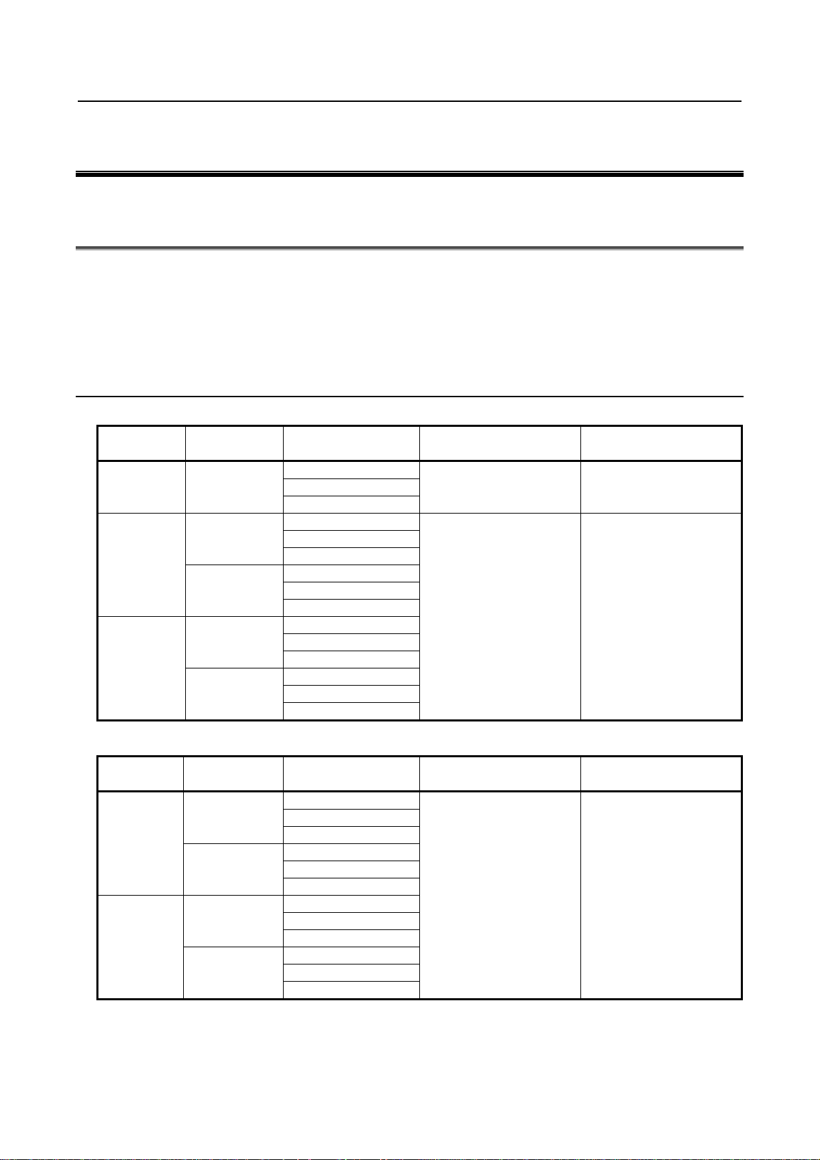
1.1.1 Configurations of LCD-mounted Type Control Units
Series 30i/31i/32i LCD-mounted type control units
Screen size Touch panel
8.4" Without
Without
10.4"
With
Without
15"
With
Number of option
slots
Without
1
2
Without
1
2
Without
1
2
Without
1
2
Without
1
2
Series 30i/31i/32i LCD-mounted type control units having the personal computer function with Windows® CE
Screen size Touch panel
Without
10.4"
With
Without
12.1”
With
Number of option
slots
Without
1
2
Without
1
2
Without
1
2
Without
1
2
Number of horizontal
soft keys
5+2 Without
10+2 8+1
Number of horizontal
soft keys
10+2 8+1
Number of vertical soft
keys
Number of vertical soft
keys
- 1 -
Page 22
1.CONFIGURATION B-64483EN/01
Screen size Touch panel
Without
15"
With
Number of option
slots
Without
1
2
Without
1
2
Number of horizontal
soft keys
10+2 8+1
Number of vertical soft
keys
CAUTION
The touch panel is a device designed to be operated by touching directly its
screen. Use a FANUC-supplied exclusive touch panel pen (A02B-0236-K111).
Touching the screen with a sharp point, such as a pen, may damage or break
the indicator surface. Touching the screen with your finger may adversely affect
operability and soil the screen. Be sure to keep away from such improper use.
NOTE
The indicators having a touch panel has a protection sheet attached to its front
surface. Explanations about how to replace the protection sheet, refer to the
FANUC Series 30i/31i/32i-MODEL B Maintenance Manual (B-64485EN).
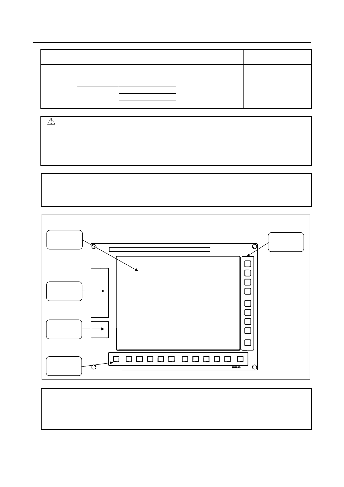
LCD-mounted type control unit (front view)
Liquid-crystal
display
Memory card
interface
USB port
(5.6)
Horizontal soft
keys
Vertical soft
keys
NOTE
1 This figure shows the 10.4” LCD-mounted control unit as viewed from the front.
The basic configuration of the other control unit models is the same, as viewed
from the front.
2 The 8.4” LCD-mounted control unit has no vertical soft key.
- 2 -
Page 23
B-64483EN/01 1.CONFIGURATION
(
y
NOTE
3 The LCD (liquid-crystal display) has been fabricated using an extreme precision
technology. However, some of their pixels may fail to light or stay constantly
lighting because of their characteristics. Please be forewarned that these
phenomena are not faults.
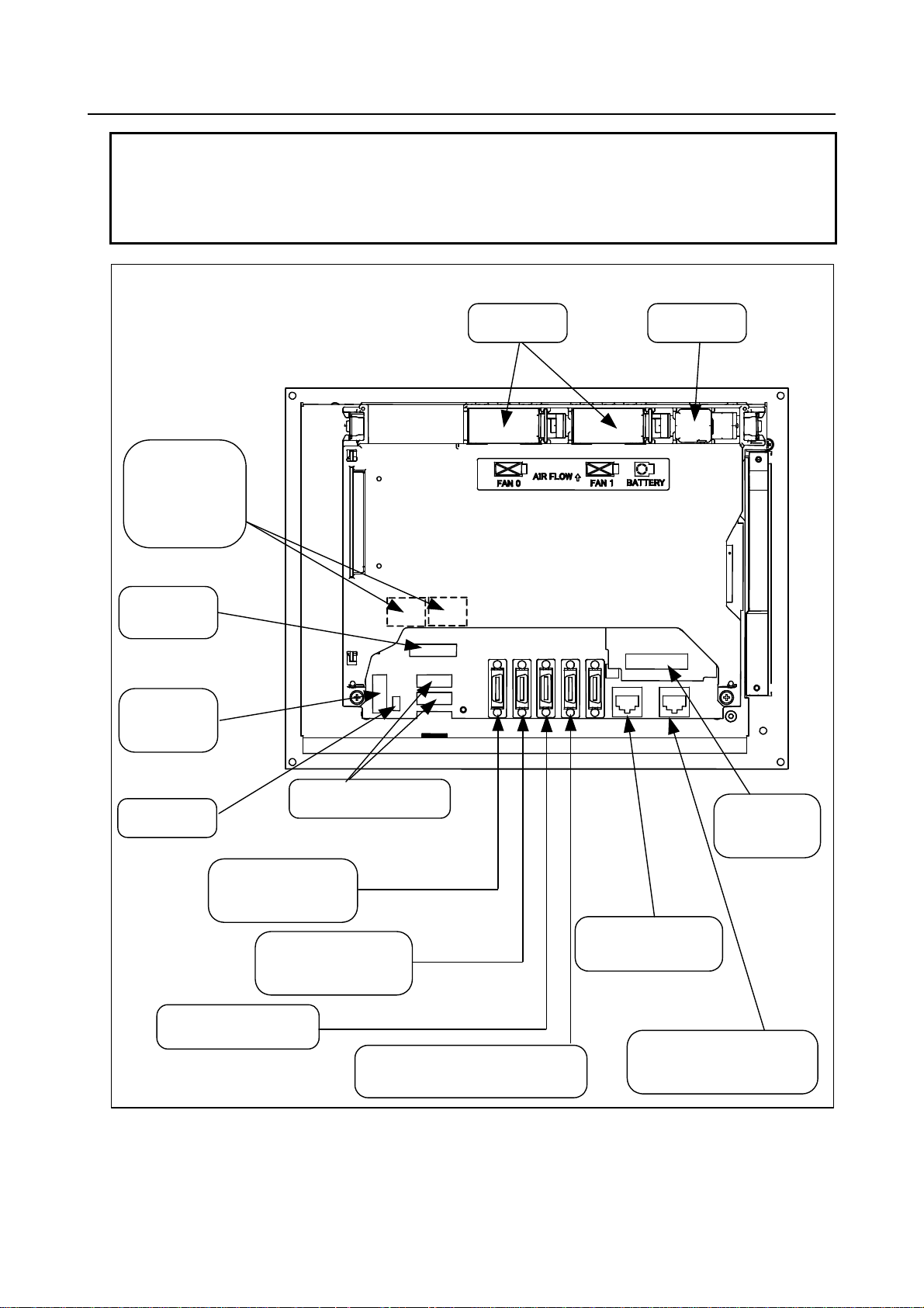
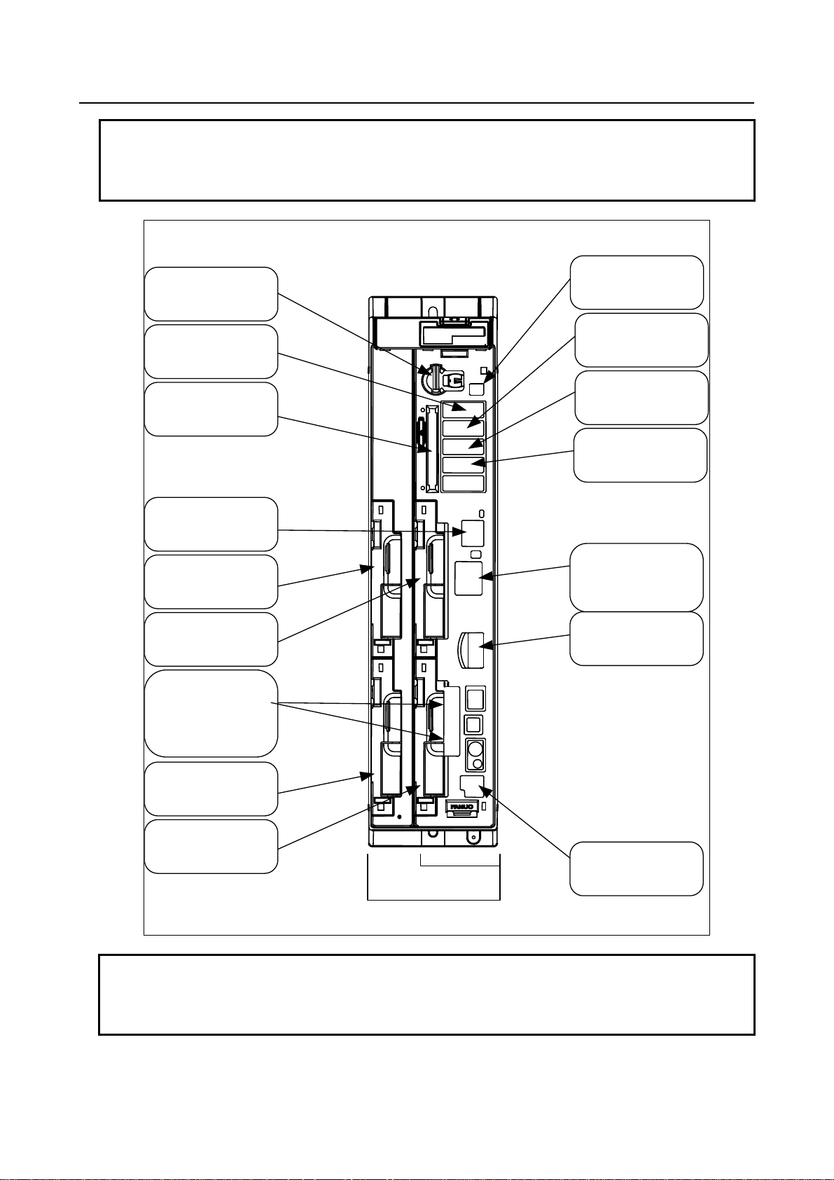
LCD-mounted type control unit (8.4”LCD unit and 10.4”LCD unit A) (rear view)
FSSB interface
connectors
[COP10A-1] (left)
[COP10A-2] (right)
(6)
MDI connector
[CA55] (5.1)
Power supply
connector
[CPD16A]
4.3)
Fan unit
Battery
(4.4)
connectors
Fuse
I/O device interface
connector (RS-232C)
[JD56A] (5.3)
High-speed skip connector
[JA40] (5.4)
Soft ke
I/O device interface
connector (RS-232C)
[JD36A/JD54] (5.3)
I/O Link i or I/O Link connector
[JD51A] (7.2)
Ethernet connector
(Embedded Ethernet)
[CD38A] (5.5)
Ethernet connector
(Multi-function Ethernet)
[CD38B] (5.5)
DeviceNet
connector [TBL]
(10)
- 3 -
Page 24
1.CONFIGURATION B-64483EN/01
y
NOTE
1 This figure shows an LCD-mounted control unit having no option slot as viewed
from the rear. For the rear view of the control units having the personal computer
function with Windows® CE, see Chapter 11, "Connection for Personal
Computer Function with Windows® CE".
2 The numbers in parentheses () in the figures are keyed to the item numbers of
the descriptions in this manual. The numbers in brackets [] in the figures are
connector numbers.
3 Connectors [COP10A-2], [TBL], [CD38A], and [CD38B] may not be provided,
depending on the specifications of the hardware.
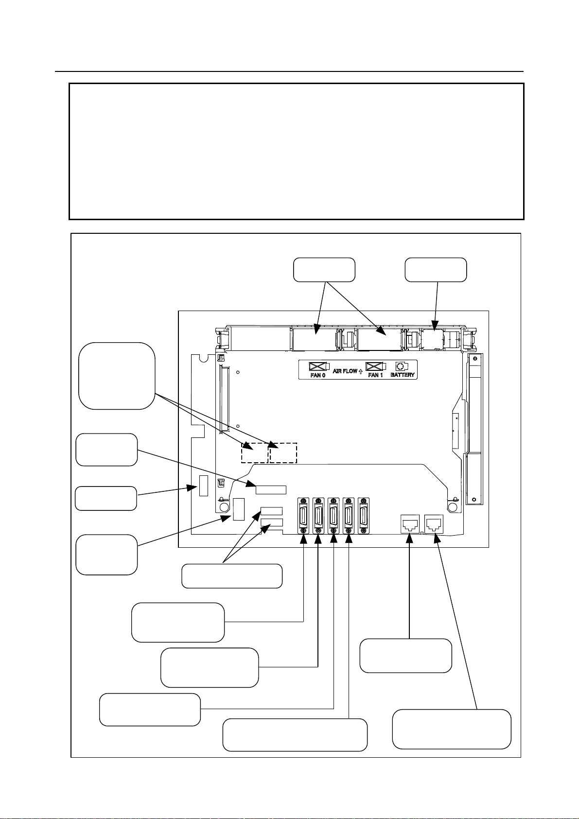
LCD-mounted type control unit (10.4”LCD unit B and 15”LCD unit) (rear view)
FSSB interface
connectors
[COP10A-1] (left)
[COP10A-2] (right)
(6)
MDI connector
[CA55] (5.1)
Fuse
Power supply
connector
[CPD16A]
(4.3)
Soft ke
connectors
Fan unit
Battery
(4.4)
I/O device interface
connector (RS-232C)
[JD56A] (5.3)
I/O device interface
connector (RS-232C)
[JD36A/JD54] (5.3)
High-speed skip connector
[JA40] (5.4)
I/O Link i or I/O Link connect or
[JD51A] (7.2)
Ethernet connector
(Embedded Ethernet)
[CD38S] (5.5)
Ethernet connector
(Multi-function Ethernet)
[CD38B] (5.5)
- 4 -
Page 25
B-64483EN/01 1.CONFIGURATION
NOTE
1 This figure shows an LCD-mounted control unit having no option slot as viewed
from the rear. For the rear view of the control units having the personal computer
function with Windows® CE, see Chapter 11, "Connection for Personal
Computer Function with Windows® CE".
2 The numbers in parentheses () in the figures are keyed to the item numbers of
the descriptions in this manual. The numbers in brackets [] in the figures are
connector numbers.
3 Connectors [COP10A-2], [CD38S], and [CD38B] may not be provided,
depending on the specifications of the hardware.
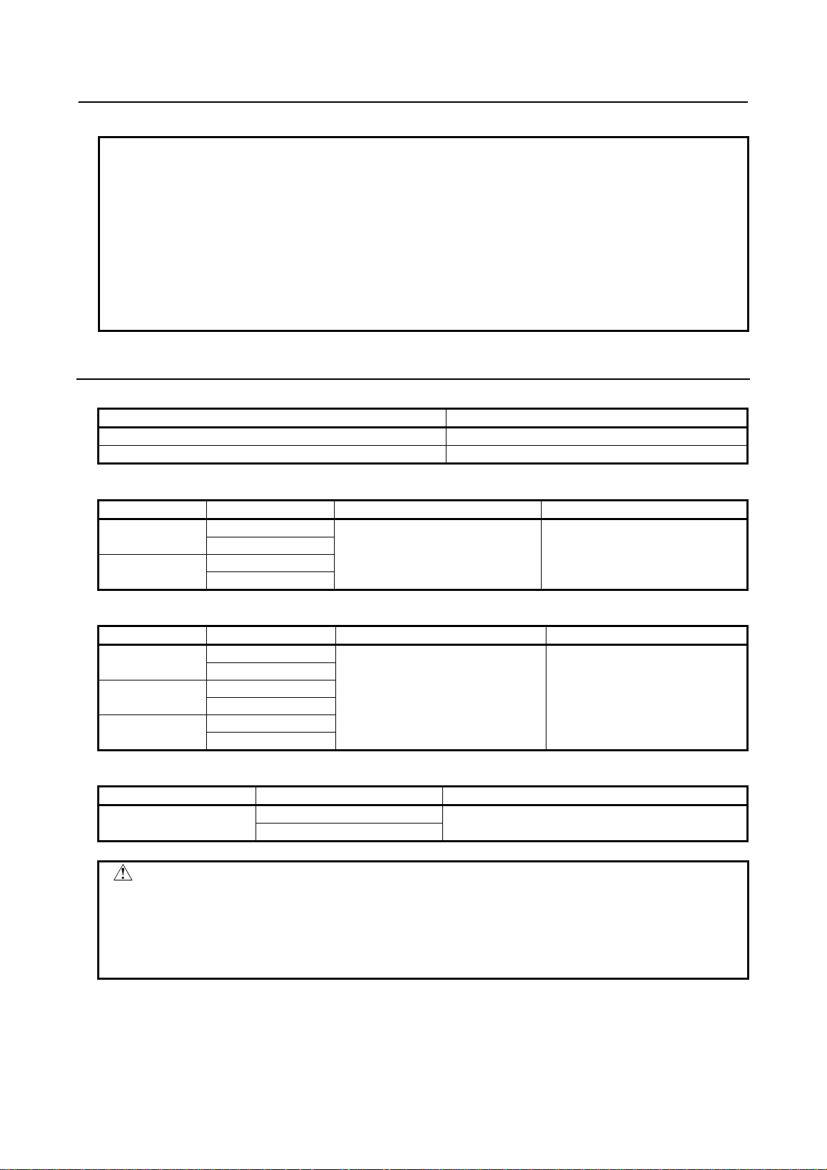
1.1.2 Configurations of Stand-alone Type Control Units
Series 30i/31i/32i stand-alone type control units
Slot rack name Number of option slots
2-slot rack 2
4-slot rack 4
Series 30i/31i/32i display units
Screen size Touch panel Number of horizontal soft keys Number of vertical soft keys
10.4"
15"
Series 30i/31i/32i display units having the personal computer function with Windows® CE
Screen size Touch panel Number of horizontal soft keys Number of vertical soft keys
10.4"
12.1”
15"
Series 30i/31i/32i display units directed to automakers
Screen size Touch panel Number of vertical soft keys
15"
CAUTION
The touch panel is a device designed to be operated by touching directly its
screen. Use a FANUC-supplied exclusive touch panel pen (A02B-0236-K111).
Touching the screen with a sharp point, such as a pen, may damage or break
the indicator surface. Touching the screen with your finger may adversely affect
operability and soil the screen. Be sure to keep away from such improper use.
Without
With
Without
With
Without
With
Without
With
Without
With
Without
With
10+2 8+1
10+2 8+1
16(left: 8, rights: 8)
- 5 -
Page 26
1.CONFIGURATION B-64483EN/01
NOTE
The indicators having a touch panel has a protection sheet attached to its front
surface. Explanations about how to replace the protection sheet, refer to the
FANUC Series 30i/31i/32i-MODEL B Maintenance Manual (B-64485EN).
Stand-alone type control unit (front view)
Battery (4.4)
I/O device interface
connector (RS-232C)
[JD56A] (5.3)
Memory card interface
Ethernet connector
(Embedded Ethernet)
[CD38A] (5.5)
Optional slot 3
Optional slot 1
FSSB interface
connectors
[COP10A-1] (lower)
[COP10A-2] (upper)
(7)
Battery connector
(4.4)
I/O device interface
connector (RS-232C)
[JD36A] (5.3)
I/O Link i or I/O Link
connector
[JD51A] (5.4)
High-speed skip connector
[JD40A] (6.1)
24-VDC power supply
connector
[CPD19A] (right)
[CPD19B] (left)
(4.3)
HSSB interface connectors
[COP21A] (5.2)
Optional slot 4
Optional slot 2
GND connection terminal
2-slot rack
4-slot rack
NOTE
The numbers in parentheses () in the figures are keyed to the item numbers of
the descriptions in this manual. The numbers in brackets [] in the figures are
connector numbers.
- 6 -
Page 27

B-64483EN/01 1.CONFIGURATION
r
y
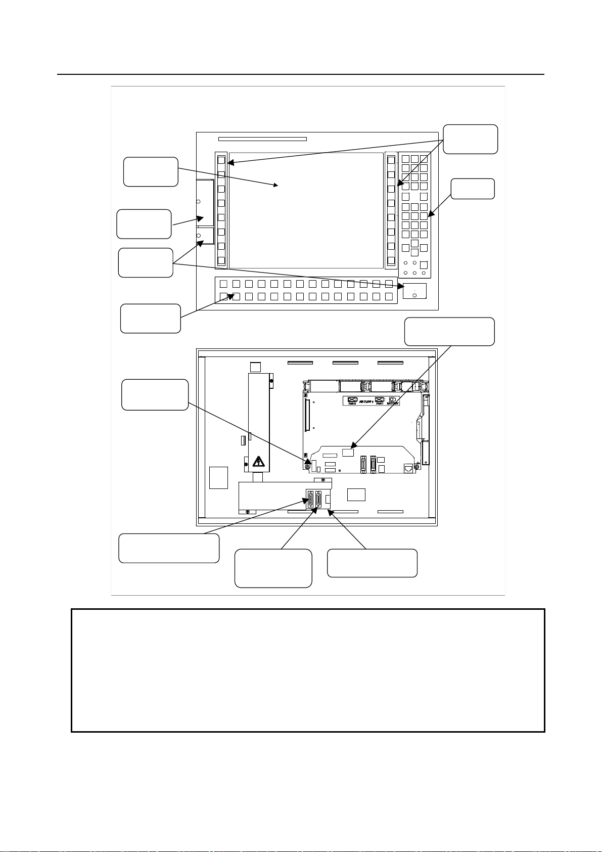
Display unit for the stand-alone type control unit (10.4”LCD unit A)
Liquid-crystal
display
Memory card
interface
USB port
(5.6)
Horizontal soft
keys
MDI interconnection
connector
(5.2)
[JA73]
Vertical soft
ke
s
Front view
Rear view
MDI connector
[CA55] (5.2)
Soft key
connectors
Video signal
interconnection connector
[CA103] (5.2)
Touch panel connecto
Fuse
Optical connector for
display control
[COP21B] (5.2)
Power supply
connectors
[CP1A]
[CP1B] (5.2)
NOTE
1 The numbers in parentheses () in the figures are keyed to the item numbers of
the descriptions in this manual. The numbers in brackets [] in the figures are
connector numbers.
2 Connectors [JA73] and [CA103], the memory card interface, and USB ports may
3 See Chapter 11 for explanations about the display unit for the control unit having
the personal computer function with Windows® CE.
4 The LCD (liquid-crystal display) has been fabricated using an extreme precision
technology. However, some of their pixels may fail to light or stay constantly
lighting because of their characteristics. Please be forewarned that these
phenomena are not faults.
- 7 -
Page 28

1.CONFIGURATION B-64483EN/01
Display unit for the stand-alone type control unit (15”LCD unit and 10.4”L CD unit B)
Vertical soft
Liquid-crystal
display
keys
Memory card
interface
USB port
(5.6)
Horizontal soft
keys
MDI connector
[CA55] (5.2)
Power supply
connectors
[CPD18] (5.2)
Front
Rear
Optical connector for
display control
[COP21M] (5.2)
Fuse
Soft key
connectors
NOTE
1 The numbers in parentheses () in the figures are keyed to the item numbers of
the descriptions in this manual. The numbers in brackets [] in the figures are
connector numbers.
2 For the display units for the control units having the personal computer function
with Windows® CE, see Chapter 11, "Connection for Personal Computer
Function with Windows® CE".
3 The LCD (liquid-crystal display) has been fabricated using an extreme precision
technology. However, some of their pixels may fail to light or stay constantly
lighting because of their characteristics. Please be forewarned that these
phenomena are not faults.
- 8 -
Page 29
B-64483EN/01 1.CONFIGURATION
Display unit for automotive for the stand-alone type control unit
Vertical soft
keys
Liquid-crystal
display
MDI
Memory card
interface
USB port
(5.2)
Function key
switches
Power supply
connector
[CPD18] (5.2)
Front
Rear
Optical connector for
display control
[COP21M] (5.2)
I/O Link i or I/O Link connector
(master side) (5.2)
I/O Link i or I/O Link
connector (slave side)
(5.2)
I/O Link adapter board
NOTE
1 The numbers in parentheses () in the figures are keyed to the item numbers of
the descriptions in this manual. The numbers in brackets [] in the figures are
connector numbers.
2 The I/O Link i and I/O Link interfaces are optional.
3 The LCD (liquid-crystal display) has been fabricated using an extreme precision
technology. However, some of their pixels may fail to light or stay constantly
lighting because of their characteristics. Please be forewarned that these
phenomena are not faults.
- 9 -
Page 30

1.CONFIGURATION B-64483EN/01
1.1.3 Configurations of Optional Boards
Additional axis board
PROFIBUS-DP sl ave board
Fast Ethernet board
HSSB interface board
PROFIBUS-DP master board
For FSSB interface
[COP10A] (6)
For Ethernet
[CD38R] (10)
For HSSB interface
[COP21A] (12.3)
DeviceNet master board
DeviceNet slave board
CC-Link remote device station board
For Profibus
[CN2] (10)
For Device NET
[TBL] (10)
For Device NET
[TBL] (10)
For Profibus
[CN1] (10)
For CC-Link
[CT1] (10)
NOTE
The numbers in parentheses () in the figures are keyed to the item numbers of
the descriptions in this manual. The numbers in brackets [] in the figures are
connector numbers.
The Fast Ethernet board may be used also as data server or FL-net functions,
depending on the settings of parameters.
- 10 -
Page 31

B-64483EN/01 1.CONFIGURATION
A
1.2 HARDWARE OVERVIEW
1.2.1 LCD-mounted Type Control Unit Overview
Main board
- CPU for controlling CNC
- Power supply
- Axis control function
- MDI I/F
- I/O Link i, I/O Link control
function
- PMC control function
- High-speed skip (HDI)
- RS-232C I/F
- Memory card I/F
Fast Ethernet board
Fast Ethernet function
Data server function
FL-net function
Additional axis board
- USB I/F
- Ethernet function
- DeviceNet function
note2
- PC functions (Windows® CE
compatible PC functions)
Basic system
dditional axis control function
HSSB interface board
High-speed serial bus interface
Various types of network boards
Options
PROFIBUS-DP master board
PROFIBUS-DP slave board
DeviceNet master board
note2
DeviceNet slave board
CC-Link remote device station board
Unit without optional slots
Unit having one optional slot
Unit having two optional slots
Note
1 On a unit with optional slots, as many optional boards as the slots can be mounted.
2 DeviceNet master functions are provided on the mainboard or on the optional board,
depending on the specification.
or
or
- 11 -
Page 32

1.CONFIGURATION B-64483EN/01
A
1.2.2 Stand-alone Type Control Unit Overview
2-slot rack 4-slot rack
Main board
Slot 3
Slot 4
Options (Slot 1 to 4)
Fast Ethernet board
Fast Ethernet function
Data server function
FL-net function
Additional axis board
dditional axis control function
HSSB interface board
High-speed serial bus interface
Various types of network boards
PROFIBUS-DP master board
PROFIBUS-DP slave board
DeviceNet master board
DeviceNet slave board
CC-Link remote device station board
Slot 1
Slot 2
Basic system
Main board
- CPU for controlling CNC
- Power supply
- Axis control function
- Display unit I/F
- I/O Link i, I/O Link control
function
- PMC control function
- High-speed skip (HDI)
- RS-232C I/F
- Memory card I/F
- Ethernet function
- 12 -
Page 33

B-64483EN/01 2.TOTAL CONNECTION DIAGRAMS
2 TOTAL CONNECTION DIAGRAMS
- 13 -
Page 34

2.TOTAL CONNECTION DIAGRAMS B-64483EN/01
A
A
Stand-alone type control unit
Control unit
Main board
24V-IN(CPD19A)
24V-OUT(CPD19B)
DISPLAY(COP21A)
I/O Link i I/O Link
HDI(JA40)
(JD51A)
{
VDC24
VDC24
To I/O device
24VDC
High-peed skip input
Distributed
I/O board
CPD1
JD1B
JD1A
CPD1
JD1B
JD1A
JD1B
JD1A
Display unit
COP21A,B,M
CP1A
CP1B
(Touch panel)
JA3
Distributed
I/O board,
I/O unit, etc.
amplifier
β
with I/O Link
CA55
24 VDC power supply
Memory card
Manual pulse generator
Operator's
panel
Power
magnetics
cabinet
Servo motor
MDI unit
CK27
PAN EL i or personal computer
R232C-1(JD56A)
R232C-2(JD36A)
FSSB(COP10A-1)
FSSB(COP10A-2)
COP10B
COP10A
COP10B
COP10A
COP10B
COP10A
COP10B
COP10A
(In this figure, a 1-axis amplifier is used.)
DC24V
To separate detector interface unit 2
Separate detector interface unit 1
CP11
COP10B
COP10A
CNF1
RS-232C I/O device
RS-232C I/O device
AC reactor
PS
αi
SP
i
α
SV
αi
SV
αi
SV
αi
SV
αi
JF101
JF102
JF103
JF104
JA4
Circuit breaker
MCC
Positio n coder
Serial s pindle motor
Circuit breaker
Servo motor
Servo motor
Servo motor
Servo motor
24VDC
200VAC
Linear scale, axis 1
Linear scale, axis 2
Linear scale, axis 3
Linear scale, axis 4
Battery for absolute scale
(Required only when an absolute scale is used)
ETHERNET(CD38A)
Ethernet
- 14 -
Page 35

B-64483EN/01 2.TOTAL CONNECTION DIAGRAMS
When optional boards are provided
Fast Ethernet board
Optional slot
Memory card
ETHERNET(CD38R)
HSSB interface board
HSSB(COP21A)
PROFIBUS-DP
master board
PROFI(CN1)
PROFIBUS-DP
slave board
PROFI(CN2)
DeviceNet
master board
DVNET(TNB)
Use a compact flash card purchased from FANUC
Ethernet or FL-net ,and so on
PANEL i
or Personal Computer
Other control unit
or PROFIBUS device
Other control unit
or PROFIBUS device
Other control unit
or DeviceNet device
DeviceNet
slave board
DVNET(TNB)
CC-Link remote
device station board
CCLNK(CT1)
Other control unit
or DeviceNet device
CC-Link device
- 15 -
Page 36

2.TOTAL CONNECTION DIAGRAMS B-64483EN/01
A
A
When one or more option boards are present
dditional axis
Optional slot
board
C reactor
αi PS
Circuit breaker
Circuit breaker
MCC
Position coder
24VDC
200VAC
FSSB(COP10A-3)
COP10B
COP10A
COP10B
COP10A
COP10B
COP10A
COP10B
COP10A
αi SP
αi SV
α
αi SV
α
i SV
i SV
Serial spindle motor
Servo motor
Servo motor
Servo motor
Servo motor
- 16 -
Page 37

B-64483EN/01 3.INSTALLATION
3 INSTALLATION
3.1 ENVIRONMENTAL REQUIREMENTS OUTSIDE THE
CABINET
3.1.1 Environmental Conditions outside the Cabinet
The control unit and the peripheral units have been designed on the assumption that they are housed in
closed cabinets. In this manual "cabinet" refers to the following:
• Cabinet manufactured by the machine tool builder for housing the control unit or peripheral units;
• Operation pendant, manufactured by the machine tool builder, for housing the display unit, MDI unit,
or operator's panel.
• Equivalent to the above.
The following table lists the environmental conditions required in installing these cabinets. Section 3.3 of
this connection manual explains the design conditions regarding installation of cabinets that will meet the
environmental conditions.
Ambient
temperature of
the cabinet
Humidity
Vibration
Meters above
sea level
Environment
Operating 0°C to 45°C
Nonoperating (including storage
and transportation)
Temperature change 0.3°C/minute or less
Normal 75%RH or less, no condensation
Short period (less than 1 month) 95%RH or less, no condensation
Operating 0.5G or less
Nonoperating (including storage
and transportation)
Operating Up to 1000 m
Nonoperating (including storage
and transportation)
Normal machine shop environment
(The environment must be considered if the cabinets are in a
location where the density of dust, coolant, organic solvent,
and/or corrosive gas is relatively high.)
-20°C to 60°C
1.0G or less
(see Note 1 in the Subsec. 3.1.2.)
Up to 12000 m
3.1.2 Installation Conditions of the Control Unit
LCD-mounted type control
unit and display unit
-20°C to 60°C
- 17 -
Ambient
temperature
Humidity
Condition
Operating 0°C to 58°C 0°C to 55°C
Nonoperating (including storage
and transportation)
Temperature change 0.3°C/minute or less
Normal 75%RH or less, no condensation
Short period (less than 1 month) 95%RH or less, no condensation
Stand-alone type control
unit
Page 38

3.INSTALLATION B-64483EN/01
Vibration
Meters above
sea level
Environment
Condition
Operating
Nonoperating (including storage
and transportation)
Operating Up to 1000m
Nonoperating (including storage
and transportation)
LCD-mounted type control
unit and display unit
0.5G or less
FANUC’s evaluation test was conducted under the following
conditions complying with IEC 60068-2-6.
10 to 58Hz: 0.075mm (amplitude)
58 to 500Hz: 1G
Direction of vibration: Each of the X, Y, and Z directions
Number of sweep cycles: 10
1.0G or less
Up to 12000m
Coolant, lubricant, or cutting chips shall not be sprinkled
directly over the CNC or servo unit. No corrosive gas shall be
allowed.
Stand-alone type control
unit
(Note 1)
NOTE
1 If the control unit is installed 1000 m or higher above sea level, the allowable
upper ambient temperature of the control unit in the cabinet is changed as
follows. Assume that the allowable upper ambient temperature of the control unit
in the cabinet installed 1000 m or higher above sea level decreases by 1.0°C for
every 100 m rise in altitude.
Example)
When a control unit whose required operating ambient temperature range is
0°C to 55°C is installed 1750 m above sea level:
55°C-(1750m-1000m)/100m × 1.0°C = 47.5°C
Therefore, the allowable ambient temperature range is from 0°C to 47.5°C.
2 When using a unit having additional installation conditions, be sure to meet also
these conditions.
3.2 CAUTIONS REGARDING THE INSTALLATION DESIGN OF
MACHINE TOOL POWER MAGNETICS CABINETS
When a cabinet is designed, it must satisfy the environmental conditions described in Section 3.1. In
addition, the magnetic interference on the screen, noise resistance, and maintenance requirements must be
considered. When mounting FANUC-supplied units, such as displays and operator’s panels, use packing
and fasten the mounting screws with the specified tightening torque. When designing magnetics cabinets,
pay due consideration to each item stated in the following “CAUTION”.
CAUTION
1 The cabinet must be fully closed. The cabinet must be designed to prevent the
entry of airborne dust, coolant, and organic solvent.
2 The cabinet must be designed so that the permissible temperature of each unit
is not exceeded. (See Section 3.3.)
- 18 -
Page 39

B-64483EN/01 3.INSTALLATION
CAUTION
3 A closed cabinet must be equipped with a fan to circulate the air within. (This is
not necessary for a unit with fan.) The fan must be adjusted so that the air
moves at 0.5 m/sec along the surface of each installed unit.
However, do not blow air from the fan directly to the unit, because doing so can
readily make dust attach the portion where the air flow hits, leading to possible
trouble. (This is not necessary for a unit with fan.)
4 For the air to move easily, a clearance of 100 mm is required between each unit
and the wall of the cabinet.
5 Each FANUC-supplied unit, such as a display or operator’s panel, has been
designed on the assumption that they will be mounted using packing and with
the specified screw tightening torque. Failing to mount them as specified can
lead to unit damage and/or malfunction. Be sure to use packing and observe the
specified screw tightening torque. (See Sections 3.6 and 3.7.)
6 Failing to use packing or to provide complete sealing, or using any packing not
resistant to coolant in use will allow dust, coolant, and organic solvent to get in
the cabinet, leading to possible equipment trouble. Be sure to use an appropriate
packing and a secure sealing.
In addition, use an appropriate packing and a secure sealing for the cable outlets
and doors of the machine builder-provided units, such as displays, operator’s
panels, and cabinet pendant boxes. (See Section 3.7.)
7 The LCD must not be installed in such a place that coolant would directly fall
onto the unit. Be sure to attach a protection cover to the LCD if it will be used in
an environment where it is anticipated that coolant may come into contact with it,
for example, an environment with a relatively dense oil mist.
8 Noise must be minimized. As the machine and the control unit are reduced in
size, the parts that generate noise may be placed near noise-sensitive parts in
the magnetics cabinet.
The control unit is built to protect it from external noise. Cabinet design to
minimize noise generation and to prevent it from being transmitted to the control
unit is necessary. (See Section 3.4.)
9 When placing units in the cabinet, also consider ease of maintenance. The units
should be placed so that they can be checked and replaced easily when
maintenance is performed.
10 The hard disk drive and floppy disk drive must not be installed near the source of
a strong magnetic field.
11 The installation conditions of the I/O unit and connector panel I/O module must
be satisfied. In order to secure ventilation in the equipment, mount the I/O unit
and connector panel I/O module in the specified orientation. Clearances of 100
mm or more both above and below the I/O unit are required for wiring and
ventilation.
Equipment radiating too much heat must not be put below the I/O unit and
connector panel I/O module.
Top
I/O base unit
(No screws or protrusions shall extend from the
bottom of this unit.)
Bottom
- 19 -
Page 40

3.INSTALLATION B-64483EN/01
3.3 THERMAL DESIGN OF THE MACHINE TOOL MAGNETIC
CABINET
The internal air temperature of the cabinet increases when the units and parts installed in the cabinet
generate heat. Since the generated heat is radiated from the surface of the cabinet, the temperature of the
air in the cabinet and the outside air balance at certain heat levels. If the amount of heat generated is
constant, the larger the surface area of the cabinet, the less the internal temperature rises. The thermal
design of the cabinet refers to calculating the heat generated in the cabinet, evaluating the surface area of
the cabinet, and enlarging that surface area by installing heat exchangers in the cabinet, if necessary.
Such a design method is described in the following subsections.
3.3.1 Temperature Rise within the Machine Tool Magnetic Cabinet
The cooling capacity of a cabinet made of sheet metal is generally 6 W/°C per 1m2 surface area, that is,
when the 6W heat source is contained in a cabinet having a surface area of 1 m
2
, the temperature of the air
in the cabinet rises by 1°C. In this case the surface area of the cabinet refers to the area useful in cooling,
that is, the area obtained by subtracting the area of the cabinet touching the floor from the total surface
area of the cabinet. There are two preconditions : The air in the cabinet must be circuited by the fun, and
the temperature of the air in the cabinet must be almost constant. For example, the operator’s panel
cabinet may contain an LCD-mounted type control unit or the display of a stand-alone type control unit.
To keep the temperature in the cabinet at 58°C or below when the ambient temperature is 45°C, the
equation below must be satisfied.
Internal heat loss P [W] ≤
2
6[W/m
⋅°C] × surface area S[m2] × 13[°C] of rise in temperature
(A cooling capacity of 6 W/°C assumes the cabinet is so large that agitation with the fan motor does not
make the temperature distribution uniform. For a small cabinet like the operator's panel, a cooling
capacity of 8 W/°C, indicated in Subsection 3.3.3, may be used.)
For example, a cabinet having a surface area of 4m
2
has a cooling capacity of 24W/°C. To limit the
internal temperature increase to 13°C under these conditions, the internal heat must not exceed 312W. If
the actual internal heat is 360W, however, the temperature in the cabinet rises by 15°C. When this
happens, the cooling capacity of the cabinet must be improved using the heat exchanger.
For the power magnetic cabinet containing a stand-alone type control unit, the internal temperature rise
must be suppressed to 55°C or less, instead of 58°C.
3.3.2 Heat Output of Each Unit
Table 3.3.2 Heat output
Unit Heat output Remarks
LCD-mounted type
control unit
Stand-alone type control unit 15W Note 1)
CPU card
DeviceNet card 3.5W
With 8.4”LCD unit 17W Note 1)
With 10.4”LCD unit A 18W Note 1)
With 10.4”LCD unit B 22W Note 1)
With 15”LCD unit 36W Note 1)
Additional heat output from a control unit having
communication features
Standard version, dedicated to the 32i
High-speed version 11W
A11, A12, A13 4W Servo card
A24, A26 6W
- 20 -
+3W
6W
Page 41

B-64483EN/01 3.INSTALLATION
Unit Heat output Remarks
Optional board
Display unit for
stand-alone type
control unit
MDI units 0W
Additional axis board 5W
Fast Ethernet board
(when used as data server functions)
HSSB interface board 4W
PROFIBUS-DP master board 5W
PROFIBUS-DP slave board 2W
DeviceNet master board 3W
DeviceNet slave board 3.5W
CC-Link remote device station board 3W
10.4”LCD unit A 13W
10.4”LCD unit A (the first display unit when two are used) 14W
10.4”LCD unit A (the second display unit when two are used) 8W
10.4”LCD unit B 23W
15”LCD unit
Display unit for automotive
3W
(3.3W)
37W
37W
NOTE
1 The values listed above do not include any heat output of the CPU card, servo
card, DeviceNet card, or option boards. To obtain the total heat output of the
control unit, add the heat output from the CPU card, servo card, DeviceNet card,
and any option boards.
2 See Chapter 6 for the heat output of the separate detector interface unit.
3 See Chapter 8 for the heat output of each I/O unit.
4 See Chapter 11 for the heat output of the control units having the personal
computer function with Windows® CE.
5 Refer to the PANEL i Connection and Maintenance Manual (B-64223EN) for the
heat output of the PANEL i.
3.3.3 Thermal Design of Operator's Panel
With a small cabinet like the operator's panel, the heat dissipating capacity of the cabinet is as shown
below, assuming that there is sufficient mixing of the air inside the cabinet.
Coated metal surfaces: 8 W/m
Plastic surfaces: 3.7 W/m
An example of the thermal design for the cabinet shown in Fig. 3.3.3 is shown below.
2
°C
2
°C
- 21 -
Page 42

3.INSTALLATION B-64483EN/01
Fig. 3.3.3
Assume the following.
Thermal exchange rates
2
Coated metal surfaces : 8 W/m
Plastic surfaces : 3.7 W/m
⋅°C
2
⋅°C
Allowable temperature rise : 13°C higher than the exterior temperature
Also, assume the following.
Dimensions of pendant type cabinet shown in Fig. 3.3.3: 560(W) × 470(H) × 150(D) mm
Surface area of metallic sections : 0.5722 m
Surface area of plastic sections : 0.2632 m
2
2
In this case, the allowable total heat dissipation for the cabinet is:
8 × 0.5722 × 13 + 3.7 × 0.2632 × 13 = 72 W.
In consequence, it can be concluded that the units shown in Table 3.3.3 on the next page can be installed
in this cabinet.
Table 3.3.3
LCD-mounted type control unit (with 10.4”LCD unit A) 18W
Additional heat output from a control unit having communication features +3W
CPU card (high-speed version) 11W
Servo card (A26) 6W
Optional board (Additional axis board) 5W
Standard machine operator's panel 15W
120-mm square fan motor for air mixing 8W
Total heat dissipation of the above
66W
(Note)
- 22 -
Page 43

B-64483EN/01 3.INSTALLATION
NOTE
The 15 W quoted for the standard machine operator's panel represents an
example heat output value when half of all the input signals are turned on. This
value varies, depending on the mechanical configuration.
3.4 COUNTERMEASURES AGAINST NOISE AND
GROUNDING
In general, noise can occur because of electrostatic coupling, electromagnetic induction, and ground loop
and get in a control unit.
On the control unit side, due consideration is paid to a protective measure for external noise. However, it
is hard to measure the magnitude and frequency of noise quantitatively and there are lots of uncertainties
with noise. So, it is important to take measures for minimizing noise occurrence and keeping any noise
from entering the control unit in order to enhance stability in CNC-based machine tool system operation.
Grounding the power magnetics cabinet and devices is very important to prevent an electric shock and
suppress a noise influence. The CNC system uses the following three types of grounding:
(1) Signal grounding
This type of grounding is used to supply a reference potential (0 V) for the electrical signal system.
(2) Frame grounding
This type of grounding is used for safety reasons as well as to suppress external and internal noise.
For example, grounding is provided for the device frames, panels, and shielding on the interface
cables connecting the devices.
(3) System grounding (PE)
This type of grounding is used to connect frame grounds, which are provided for the individual
devices or between the units, to the ground as a system at a single point.
When designing the power magnetics cabinet, guard against noise in the machine as described in the
following section.
- 23 -
Page 44
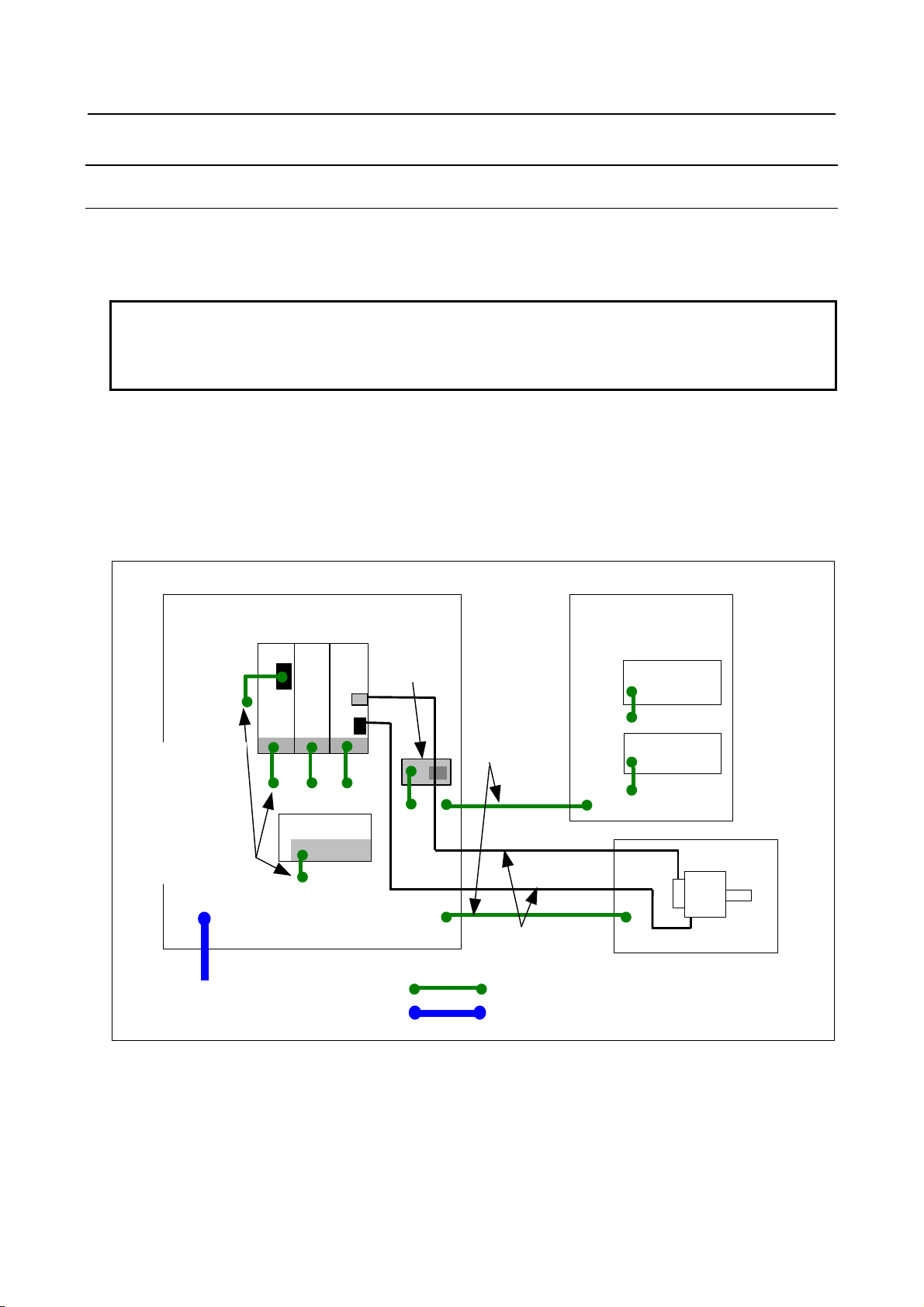
3.INSTALLATION B-64483EN/01
α
α
α
(
)
3.4.1 Grounding as Noise Suppression Measures
3.4.1.1 Grounding methods
Typically, noise that becomes a problem is high–frequency noise. To suppress high–frequency noise, it is
important that the devices are grounded at low impedance
(NOTE)
.
The grounding schemes for this purpose are described below.
NOTE
Impedance includes a resistance component that converts electric current to
heat as well as a component called “reactance”, and indicates a characteristic of
resistance to the flow of alternating current at a certain frequency.
(1) Multipoint grounding scheme
In this grounding scheme, when grounded at sufficiently low impedance, the cabinet metal plates are used
as ground plates, to which grounding is provided in the vicinity of each device.
This scheme has a great effect of suppressing high–frequency noise because it enables grounding to the
low–impedance metal plates of the cabinet in the shortest distance. However, the noise suppression effect
depends on the cabinet structure because the cabinet metal plates are used as ground plates.
See Subsection 3.4.1.2 for the cabinet. Fig. 3.4.1.1 (a) is a schematic wiring diagram.
i
Cabinet
PS
i
SV
Ground bar for
shield clamp
JF*
i
SP
(Lower-impedance metal plates)
(Lower-impedance metal plates)
Pendant box
Control unit
Connect the unit
to a metal plate
close to it.
However, keep
signal grounding
points at least
10 cm away
from power wire
grounding
points.
PE terminal (for connecting external
protective conductor)
Do not coat mating surfaces.
Grounding electrode or main
grounding termina l
24 V output power
AC input
Connection at
low impedance
Signal line
Power line
Separate the signal line
and power line when
routing them.
Frame grounding
System grounding (PE)
Machine
operator’s panel
Machine side
Motor
Fig. 3.4.1.1 (a) Schematic diagram for multipoint grounding scheme
When the multipoint grounding scheme is adopted, the units can be grounded at low impedance, and
ground wires (wires from the unit’s ground terminal to a grounding plate) can be shortened, so that wiring
may be simplified.
- 24 -
Page 45

B-64483EN/01 3.INSTALLATION
α
α
A
α
CAUTION
If it is impossible to configure cabinet metal plates with a low impedance, it is
likely that noise may effect grounding circuits shared by power wires and signal
wires.
(2) Single–point grounding scheme
In this grounding scheme, grounding separation is achieved between the signal system and power system,
and grounding is provided at a single point to suppress the noise influence of the power system on the
signal system.
This scheme tends to need longer connection wires for grounding the devices. To produce a sufficient
effect of suppressing high–frequency noise, it is therefore necessary to use larger–diameter wires or use
two or more wires for each connection. Fig. 3.4.1.1 (b) is a schematic wiring diagram.
chieve grounding
separation between
the signal system
and power system.
Grounding electrode or
main grounding terminal
Cabinet
i
PS
i
i
SP
SV
JF*
Power system ground
bar
24 V output power
AC input
Signal system
ground bar
PE terminal (for connecting
external protective conductor)
Ground bar for
shield clamp
Signal system ground bar
Signal line
Power line
Separate the signal line
and power line when
routing them.
Frame grounding
System grounding (PE)
Pendant box
Control unit
operator’s panel
Machine
Machine side
Motor
Fig. 3.4.1.1 (b) Schematic diagram for multipoint grounding scheme
3.4.1.2 Cabinet
A cabinet is an important element in improving noise immunity and suppressing radiated noise. One of
the causes of problems related to noise immunity and radiated noise is faulty electrical continuity between
the metal plates that make up the cabinet. Typically, noise that becomes a problem is high–frequency
noise, against which measures must be taken in the cabinet design.
- 25 -
Page 46

3.INSTALLATION B-64483EN/01
(1) Basic cabinet structure
A cabinet should basically be made of metal.
To improve noise immunity, there must be low–impedance electrical continuity between the metal plates
that make up the cabinet, which are the side plates, top plate, and bottom plate, and a welding–type
cabinet structure is recommended.
As for a cabinet welding method, bead welding is more suitable than spot welding for providing
low–impedance electrical continuity between the metal plates.
For an assembly–type cabinet structure, provide electrical continuity by bringing the metal plates into
direct contact with each other, without applying a coating to their joint surface areas.
In a structure that has the metal plates connected only with wires because of structural constraints,
low–impedance connections are more difficult to make than in a structure in which welding is made or
the metal plates are brought into direct contact with each other. It is necessary to maintain sufficient
levels of items such as the cross–sectional area of a wire to use, continuity of connections, and contact
areas.
Bead welding
Fig. 3.4.1.2 (a) Cabinet structure
Bring the metal plates into direct contact with each
other, without applying a coating to their joint areas.
NOTE
Explained above is how to provide cabinets with low-impedance electrical
continuity so as to increase noise immunity and to suppress noise radiation. See
Subsection 3.4.2 for conditions required to configure protective grounding
circuits.
(2) Mounting units on the cabinet
The shortest possible lengths of unit ground wires (wires from the unit’s ground terminal to a grounding
plate) should be used to make connections. A ground wire with a small conductor diameter causes
impedance to high-frequency noise to become particularly higher, leading to an insufficient grounding
effect. For the location of the ground terminal of each unit, refer to the manual relevant to the unit. The
following shows the recommended method by which the metal plate with the unit mounted is installed on
the cabinet. Care should be taken so that the cabinet and metal plate are connected to each other on their
broad areas with no coating. It is not recommended that electrical continuity be provided only by screws,
because impedance to high frequency cannot be sufficiently low.
- 26 -
Page 47

B-64483EN/01 3.INSTALLATION
<Good example>
Coating
mask
Coating
Metal plate
Cabinet
Screw
Shortest connection
with thick ground wire
Cabinet
Metal
plate
Unit
Continuity on areas
with no coating
<Bad example>
Cabinet
Metal
plate
Unit
Continuity only by screw
in a coated area
Thin ground wire, long
ground wire
Fig. 3.4.1.2 (b) Installing a unit in a cabinet
- 27 -
Page 48

3.INSTALLATION B-64483EN/01
3.4.2 Protective Ground (Grounding for Protection against Indirect
Contact)
Protection against indirect contract is intended to prevent the risk that may occur in a conductive portion
which is not charged with electricity (applied with voltage) during normal operation but may be charged
with electricity if insulation is accidentally destroyed. It must be implemented by:
- measures to prevent the occurrence of a touch voltage, or
- automatic disconnection of the supply before the time of contact with a touch voltage can become
hazardous
As for protective grounding in “automatic disconnection of the supply before the time of contact with a
touch voltage can become hazardous”, follow any standards the machine tool is supposed to meet. Some
standard examples follow:
Regarding protection against indirect contract
IEC 60364-4-41:2001 and JIS C 60364-4-41:2006 (Electrical installations of buildings - Part 4-41:
Protection for safety - Protection against electric shock) 413
Regarding the minimum cross-sectional area of protective conductors
IEC 60204-1:2005 and JIS B 9960-1:2008 (Safety of Machinery – Electrical Equipment of
Machines – Part 1: General Requirements) 8.2.2
NFPA 79:2007 (Electrical Standard for Industrial Machinery) 8.2.2 Equipment Grounding
(Protective) Conductors and Bonding Jumpers
NFPA 79:2007 (Electrical Standard for Industrial Machinery) 18.2 Continuity of the Equipment
Grounding (Protective Bonding) Circuit
Regarding the cross-sectional area of a protective conductor shared by multiple circuits
IEC 60364-5-54:2002 and JIS C 60364-5-54:2006 (Electrical installations of buildings – Part 5-54:
Selection and erection of electrical equipment – Earthing arrangements, protective conductors and
protective bonding conductors) 543.1.4
Regarding use of enclosures (cabinets) or frames as protective conductors
IEC 60204-1:2005 and JIS B 9960-1:2008 (Safety of Machinery – Electrical Equipment of
Machines – Part 1: General Requirements) 8.2.3
IEC 60364-5-54:2002 and JIS C 60364-5-54:2006 (Electrical installations of buildings – Part 5-54:
Selection and erection of electrical equipment – Earthing arrangements, protective conductors and
protective bonding conductors) 543.2.2, 543.2.3;
NFPA 79:2007 (Electrical Standard for Industrial Machinery) 12.2.1 Conductor Material
- 28 -
Page 49

B-64483EN/01 3.INSTALLATION
3.4.3 Connecting the Ground Terminal of the Control Unit
Continuity between the control unit’s and a 0 V terminals
CAUTION
In each control unit, the 0 V and ground terminals are electrically connected to each
other. So, do not connect any external unit’s 0 V connected to the control unit’s 0 V to
any other line’s grounding electrode that can have an electrical potential different
from that of the grounding electrode connected to the control unit.
Machine
Control unit
Control
signal
0V
I/O module
DOCOM
Output
signal
0V
Power magnetics cabinet
+24V
24 VDC
output
power
Relay
0V
Control unit’s ground terminal
Machine-side main ground terminal
(main ground bus)
Grounding electrode
Fig. 3.4.3 (a) Continuity between the control unit’s ground and 0 V terminals
- 29 -
Page 50

3.INSTALLATION B-64483EN/01
Connecting the ground terminal of an LCD-mounted type control unit
Connect the 0 V line in the control unit to the cabinet’s metal plate or signal system ground bar nearby via
the protective ground terminal (see below).
Rear view
Protective
ground terminal
(
M4 stud)
Side view
Electric wire
2
(2 mm
or thicker)
Protective ground
tap on cabinet’s
Signal system ground bar
Multiple-point grounding
Single-point grounding
metal plate
Fig. 3.4.3 (b) Ground terminal connection
- 30 -
Page 51

B-64483EN/01 3.INSTALLATION
Connecting the ground terminal of a stand-alone type control unit
Connect an electronics circuit’s 0 V line in the control unit to the cabinet’s metal plate or signal system
ground bar close to it via the signal ground terminal.
Use the Faston terminal (FANUC specification: A02B-0166-K330).
Front Side
4-slot rack
2-slot rack
Frame ground
Signal ground terminal
(Faston terminal)
Electric wire
2
or thicker)
(2 mm
Signal system ground bar
Multiple-point grounding:
Connect the 0 V line to a nearby
metal plate connected electrically
to a grounding electrode.
Single-point grounding:
Connect the 0 V line to the signal
ground bar connected electrically to a
grounding electrode.
Frame ground
Fig. 3.4.3 (c) Ground terminal connection
- 31 -
Page 52

3.INSTALLATION B-64483EN/01
3.4.4 Separating Signal Lines
The cables used for the CNC machine tool are classified as listed in the following table. Process the
cables in each group as described in the action column.
Table 3.4.4 Cable grouping
Group Signal line Action
A
B
C
Primary AC power line
Secondary AC power line
AC/DC power lines (containing the power lines
for the servo and spindle motors)
AC/DC solenoid
AC/DC relay
DC solenoid (24 VDC)
DC relay (24 VDC)
DI/DO cable between the I/O unit and power
magnetics cabinet
DI/DO cable between the I/O unit and machine
24 VDC input power cables connected to the
control unit and its peripherals
I/O Link i or I/O Link cable
Cable for the position coder
Cable for the manual pulse generator
Cable for the MDI
RS–232C interface cable
Cable for the battery
Cable for the Ethernet
Other cables for which shield processing is
specified
(Note 3)
Bind the cables in group A separately
groups B and C, or cover group A with an
electromagnetic shield
See Subsection 3.4.5 and connect spark killers or
diodes with the solenoid and relay.
Connect diodes with the DC solenoid and relay.
Bind the cables in group B separately from group
A, or cover group B with an electromagnetic
shield.
Separate group B as far from group C as
possible.
It is desirable to apply shield processing
described in Subsection 3.4.6.
Bind the cables in group C separately from group
A, or cover group C with an electromagnetic
shield.
Separate group C as far from group B as
possible.
Be sure to perform shield processing as
described in Subsection 3.4.6.
(Note 2)
.
NOTE
1 Binding the cables in one group separately from another means that the groups
are placed 10 cm or more apart from one another.
2 Covering a group with an electromagnetic shield means that shielding is
provided between groups with grounded steel plates.
3 The shield is not required when the cable for the MDI is no more than 50 cm in
length.
(Note 1)
from
- 32 -
Page 53

B-64483EN/01 3.INSTALLATION
A
To motor
and the like
24VDC
power
supply
Spindle
amp lifier
Cabinet
Fig. 3.4.4 Cable layout example
3.4.5 Noise Suppressor
Servo
amp lifier
I/O
Unit
Duct
Shielding
plate
Cable of group A Cable of group B, C
Section of duct
Group A
Group B, C
Shielding plate
Pendant box
Control
unit
Unit
rece iv ing
C
voltage
Actuators, such as solenoids and relays, used in power magnetics cabinets need a noise suppressor.
Because an actuator, which converts electrical energy to mechanical action, is an inductive load, it
resonates with the parasitic capacitance in a circuit containing it, when it works on and off, thus
generating intermittent arcs accompanied by abrupt voltage rises and falls at its contacts, hence
electromagnetic waves interfering with electronics circuits. As a remediation measure, treat the inductive
load as described below.
1) While referencing the processing for cable groups A and B described in Subsection 3.4.4,
“Separating Signal Lines”, apply a CR snubber circuit and a diode, respectively, to an inductive load
in an AC circuit and that in a DC circuit.
2) When selecting a CR snubber or diode, observe the following cautions.
Cautions for selecting and using a CR snubber
• Use a CR snubber in an AC circuit.
A varistor, voltage clamping element, can limit the peak of an oscillating voltage waveform but
cannot relax an abrupt voltage transition . For this reason, we recommend using a CR snubber rather
than the varistor.
• Determine the rating of the resistor and capacitor in the CR snubber according to the steady-state
current I (A) and DC resistance RL (Ω) of the inductive load as follows:
)(RLRΩ≅
1) CR snubber resistance:
2
2) CR snubber capacitance:
I
10
• Place the CR snubber close to the inductive load to minimize its wiring.
2
I
C
(μF)
≤≤
20
- 33 -
Page 54

3.INSTALLATION B-64483EN/01
r
Inductive load (such as relay)
CR snubber
Moto
General-purpose induction motor
Fig. 3.4.5 (a) Example of applying a CR snubber
Cautions for selecting and using a diode
• A diode (freewheeling diode) can be used as a noise suppressor for a DC driver circuit.
• Determine the ratings of the diode according to the drive voltage and current for the inductive load
(such as a solenoid coil, relay, or motor) as follows:
1) Voltage rating: Approximately twice the voltage applied to the inductive load
2) Current rating: Approximately twice the steady-state current flowing through the inductive load
• Place the diode close to the inductive load in order to minimize its wiring.
+
Diode
図3.4.5 (b) Example of applying a diode
Inductive load (such as a relay)
3.4.6 Cable Clamp and Shield Processing
Some cables that are drawn into the control unit, servo amplifier, or spindle amplifier need shielding
(basically, every signal line needs shielding). Clamp all these cables in the way shown below. This type
of clamping works for both cable supporting and shielding. Be sure to make clamping because it is quite
important to make system operation stable. Clamping shield correctly can suppress effect from external
noise.
Partially peel the sheath off a cable and expose the shield, and press the exposed portion against the
ground bar with the clamp. Care should be taken so that the ground bar and shield have a surface contact
in a larger area. (See the figure below.)
The machine builder is requested to prepare the ground bar for cable clamping and place it as shown
below.
When the multipoint grounding scheme is used, care should be taken so that the ground bar for the shield
clamp and cabinet are connected at low impedance by, for example, preventing the cabinet side contact
surface from being coated.
- 34 -
Page 55

B-64483EN/01 3.INSTALLATION
When using an in-line connector or the like to split a cable, it is necessary to connect the shield of one
portion of the cable and that of the other portion and to keep the total impedance of the two cable portions
from becoming high. Even if the connector is placed at the inlet of the cabinet, it is also necessary to use
the shield for the intra-cabinet portion of the cable all the way to the other end of the cable.
Ground bar for shield clamp
Cable
Metal fittings
for clamp
40 mm to 80 mm
Fig. 3.4.6 (a) Cable clamp (1)
NOTE
1 Select a cable with a proper length.
2 If the cable is too long, the noise immunity may be reduced or noise may be
caused on other cables. In addition, when the excess length is coiled, the
inductance is increased and a high voltage is induced during turning on or off of
signals. This may cause a failure or a malfunction due to noise.
3 Bundle and clamp the shields of cables that lead into the control unit or amplifier
at a point, respectively, close to the unit or amplifier.
Control unit
Cabinet
Ground bar for shield clamp
Metal fittings for clamp
Shield
Fig. 3.4.6 (b) Cable clamp (2)
- 35 -
Page 56

3.INSTALLATION B-64483EN/01
Prepare a ground bar for cable clamping shown below.
Ground terminal
(grounded)
Hole for securing metal
fitting clamp
Mount screw hole
Fig. 3.4.6 (c) Ground bar for shield clamp (outline drawing)
The ground bar for cable clamping must be made of a steel plate at least 2 mm thick and plated with
nickel.
12
Fig. 3.4.6 (d) Ground bar for shield clamp (hole arrangement and dimension drawing)
8
20
Ground bar for shield clamp
(Unit: mm)
Reference)
Max. 55
6
Fig. 3.4.6 (e) Clamping metal fixture (outline drawing)
Ordering specification for metal fittings for clamp
A02B-0303-K001 (8 pieces)
- 36 -
28
17
(Unit: mm)
Page 57

B-64483EN/01 3.INSTALLATION
A
(
)
(
)
A
b
(
)
3.4.7 Lightning Surge Absorber Installation
It is recommended to install a surge absorber between input power lines and between input power lines
and the ground in order to protect equipment from thunderbolt-caused voltage surges. However, installing
a surge absorber does not always ensure protection from lightning surges.
For recommended lightning surge absorbers, refer to your respective servo amplifier descriptions.
Installation procedure
The surge-absorbing elements used for measures against surges due to lightening must be installed in the
input power unit as shown in the figure below. The figure below shows an example in which an
insulating transformer, shown by dotted lines, is not installed. If an insulating transformer is installed,
surge-absorbing element 2 (between line and ground) is not required.
Circuit
breaker
MCCB
To control power input for control unit
24 VDC power and control power
supply input of Power Supply for
servo amplifier
C
input
R
S
T
PE
Circuit
breaker
(MCCB)
Insulating
transformer
Circuit
breaker
5A,MCCB
a
Circuit
breaker
MCCB
Magnetic
contactor
To other electric parts on the machine
C
reactor
To main circuit
power input of
Power Supply for
servo amplifier
Surge-absorbing element 1
(between lines)
Surge-absorbing element 2
(between line and ground)
Fig. 3.4.7 Example of installing lightning surge ab sorbers on 200 VAC lines
CAUTION
1 For a better surge absorbing effect, the wiring shown by heavy line must be as
short as possible.
Wire size : Cross-sectional area at least 2 mm2 large
Wire length: The sum of the length (a) of the wire for the connection of
surge-absorbing element 1 and that (b) of surge-absorbing element
2 must be 2 m or less.
2 If conducting dielectric strength tests by applying overvoltages (1000 VAC and
1500 VAC) to the power line, remove surge-absorbing element 2. Otherwise, the
overvoltages would activate the element.
- 37 -
Page 58

3.INSTALLATION B-64483EN/01
A
AAA
A
A
CAUTION
3 The circuit breaker (5A) is a short circuit protection of lines if the surge-absorbing
elements result in short circuit breakdown due to the absorption of an excessive
amount of energy.
NOTE
The circuit breaker (5A) can be used also for other electric parts on the machine
because no current flows through surge-absorbing elements 1 and 2 in the
normal state. The “other electric parts on the machine” can be the control power
supply of Power Supply for servo unit and the power supply for the fan motor for
a spindle motor.
3.5 INSTALLING THE CONTROL UNIT
CAUTION
The control unit has a built-in fan motor. Failing to secure a space sufficient to
maintain a satisfactory air flow in the control unit can lead to abnormal heat
generation and faults.
3.5.1 Installing the LCD-mounted Type Control Unit
Air enters the control unit through the bottom and is drawn through the fan motor which is located on the
top of the control unit.
Space
should be provided whenever possible. When space
placed in the immediate vicinity which could obstruct the air flow.
, shown in Fig. 3.5.1, must be provided to ensure unrestricted air flow. Also, space B
B
cannot be provided, ensure that nothing is
IR FLOW
50mm
IR FLOW
Rear view
50mm
B B
Fig. 3.5.1
- 38 -
B
Page 59

B-64483EN/01 3.INSTALLATION
A
App
A
r
A
A
3.5.2 Installing the Stand-alone Type Control Unit
Air is fed into the bottom of the unit and output from the fan motor mounted on the top of the unit.
The spaces shown in Fig. 3.6.2 (areas
Also, adequate service access space is required in front of and at the top of the unit so that printed circuit
boards and the fan motor can be replaced easily if necessary.
There is a spare connector located at the far end (at middle height) on the right side of the control unit.
This connector is used for control unit testing and other purposes. Therefore, space (area
handling the connector is required.
Spac e for air flow, and access area for fan unit replacement
2-slot rack: Approx. 65
4-slot rack: Approx. 95
and B) are always required to ensure smooth air flow.
30
rox. 180
C
) for
50
380
50
B
ccess space fo
spare connector
C
Spare connector
B
80
Sufficient space for
replacing a printed circuit
board is required.
Fig. 3.5.2
Unit: mm
- 39 -
Page 60
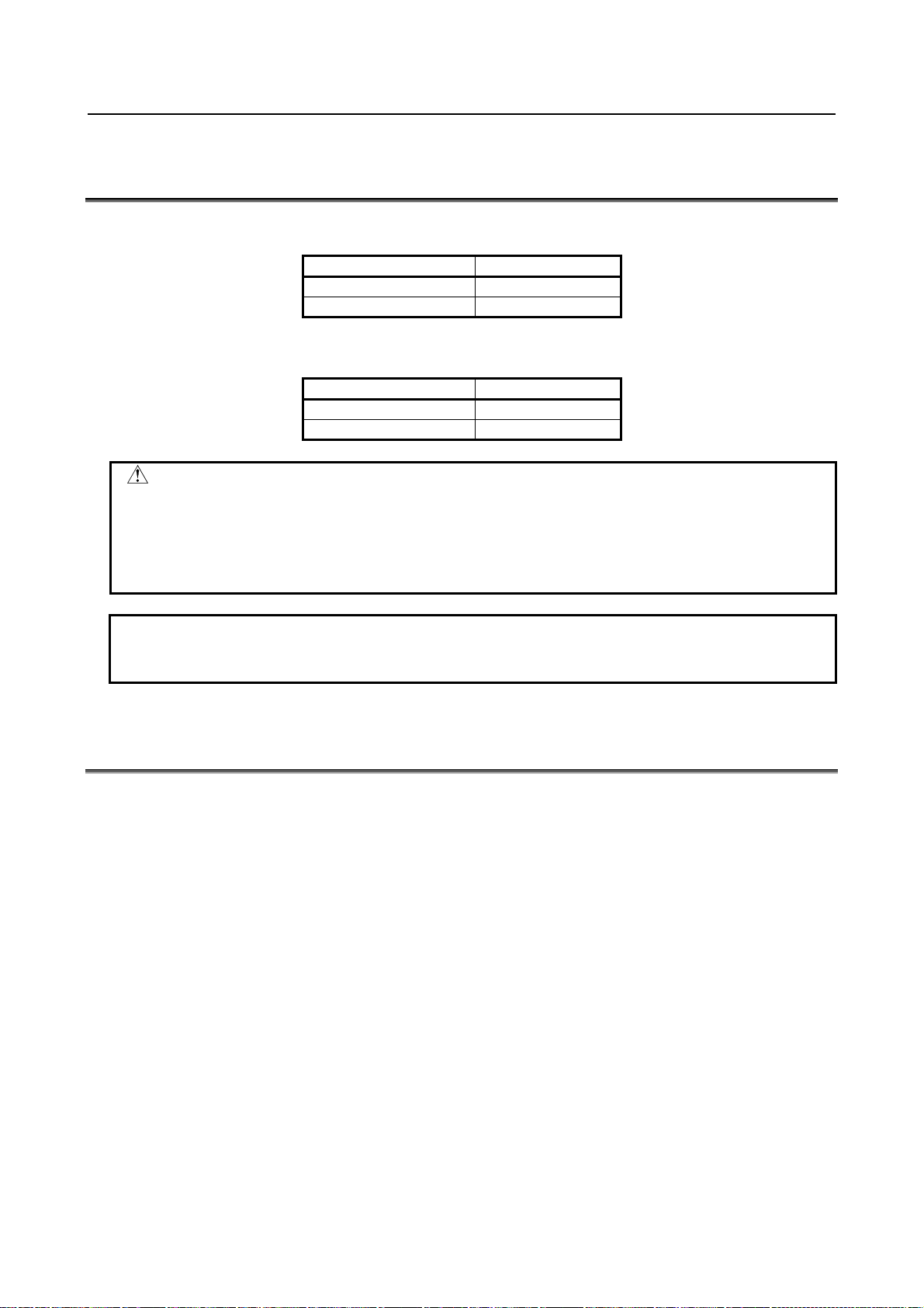
3.INSTALLATION B-64483EN/01
3.6 TIGHTENING TORQUE FOR FASTENING UNITS AND
GROUND TERMINALS
The following table lists the tightening torque for screws and nuts used to fasten the units (except those
having molded mounting parts) explained herein and ground terminals in the units.
Screw and nut diameter Tightening torque
M3 0.8 to 1.0 N⋅m
M4 1.6 to 2.0 N⋅m
The following table lists the tightening torque for screws and nuts used to fasten those units having
molded mounting parts, such as stand-alone control units and separate detector interface units.
Screw and nut diameter Tightening torque
M4 1.1 to 1.5 N⋅m
M5 2.4 to 2.8 N⋅m
CAUTION
Be sure to observe the rules listed above when tightening screws. If screws are
tightened too weakly or too strongly, it is likely that the unit may drop, break, or
malfunction.
For units having a touch panel in particular, be sure to observe the above rules.
Failing to observe them can cause the touch panel to malfunction.
NOTE
For units having different installation conditions specified herein, observe them
first.
3.7 DUSTPROOF MEASURES FOR CABINETS AND
PENDANT BOXES
When designing and manufacturing cabinets or pendant boxes for housing displays and operator’s panels,
they are requested to observe the following cautions to make their structures resistant to intrusion of dust,
cutting chips, coolant, organic solvent, and oil mist because these cabinets and pendant boxes are
susceptible to them.
1) The cabinet and pendant box must be of a hermetically sealed structure.
2) Apply packing to the panel mounting surface to which a display and operator's panel are to be
mounted.
3) Make sure that the door packing of the cabinet and pendant box is sealed firmly.
4) For a cabinet or pendant box with a rear cover, apply packing to the mounting surface.
5) Make sure that the cable entrance is sealed with packing, connectors for conduits, etc.
6) Make sure that all other openings are blocked, if any.
7) Pay due consideration to keep the display and operator’s panel from direct exposure to cutting chips
and coolant; do not let any coolant come into contact with them.
8) Coolant can readily form puddles on the cabinet and pendant box and may drop on the panel surface
of the display and operator’s panel. Use such a structure that can prevent coolant from forming
puddles on the display and operator’s panel or dropping on the panel surface.
- 40 -
Page 61

B-64483EN/01 3.INSTALLATION
WARNING
Coolants containing sulfur or chlorine at a high activation level, oil-free coolants
called synthetic, and water-soluble coolants at a high alkali level, in particular,
can largely affect the CNC and peripheral units. Please note that, even if
consideration is taken to protect them from direct exposure to these coolants,
the following trouble is likely to occur.
- Coolants containing sulfur or chlorine at a high activation level
Some coolants containing sulfur or chlorine are at an extremely high activity
level. If such a coolant adheres to the CNC or peripheral units, it reacts
chemically with a material, such as resin, of equipment, possibly leading to
corrosion or deterioration. If it gets in the CNC or a peripheral unit, it corrodes
metals, such as copper and silver, used as component materials, possibly
leading to a defective component.
- Synthetic-type coolants having a high permeability
Some synthetic-type coolants whose lubricating component is, for example,
PAG (polyalkylene glycol) have an extremely high permeability. If such a
coolant is used even in equipment having a high closeness, it can readily flow
into the equipment through, for example, gaskets, or packing. It is likely that,
if the coolant gets in the CNC or a peripheral unit, it may deteriorate the
insulation and damage the components.
- Water-soluble coolants at a high alkali level
Some coolants whose pH is increased using alkanolamine are so strong
alkali that its standard dilution will lead to pH10 or higher. If such a coolant
spatters over the surface of the CNC or peripheral unit, it reacts chemically
with a material, such as resin, possibly leading to corrosion or deterioration.
- 41 -
Page 62

3.INSTALLATION B-64483EN/01
A
When making screw holes in packing, be careful not to cut to the edge of the packing. Any extra cut can let
coolant get in the cabinet through the screw hole, causing trouble.
Packing
Screw hole
*) When making screw holes in packing, be careful not to cut to the edge of the packing.
ny extra cut can let coolant
get in the cabinet through the
Packing
Screw hole
screw hole.
Packing for LCD units, MDI units, and standard machine operator’s panels
Observe the following rough standards for the thickness and hardness of packing used with LCD units
(included LCD-mounted control units or display units), MDI units, and standard machine operator’s
panels.
Thickness : 1.4mm(including double-stick tape)
Hardness : 8(Asker C)
The following models of packing can be purchased from FANUC. These models are electrically
conductive. When they are used to mount a unit on a cabinet or pendant box, they leave no electrical gap
between the unit and cabinet or pendant box, being effective in electromagnetic wave shielding and EMC
measures.
Ordering information Use
A02B-0323-K302 For 8.4” LCD unit, for standard MDI unit (ONG 8.4” LCD unit)
A02B-0323-K301 For 10.4” LCD unit, for standard MDI unit (ONG vertical type)
A02B-0323-K300 For 12.1” LCD unit
A02B-0323-K304 For 15” LCD unit
A02B-0323-K306 For display unit for automotive
A02B-0323-K310 For standard MDI unit (ONG vertical type)
A02B-0323-K313 For small MDI unit (ONG 8.4” LCD unit)
A02B-0323-K314 For standard MDI unit (QWERTY)
A02B-0323-K315 For standard MDI unit (QWERTY type B)
A02B-0323-K320 For main panel of standard machine operator’s panel
CAUTION
1 We have evaluated the above models of packing for many different coolants.
However, we do not necessarily guarantee that they are resistant to all coolants.
They are not resistant to, for example, coolants containing sulfur or chlorine at a
high activation level and water-soluble coolants at a high alkali level.
2 When attaching these models of packing, observe the cautions provided
together with them.
When using packing to install a LCD unit, MDI unit, or standard machine operator’s panel in a cabinet or
pendant box, be careful not to pinch the packing between the mounting surface of the cabinet or pendant box
and the brim of the unit being installed.
- 42 -
Page 63

B-64483EN/01 3.INSTALLATION
When attaching packing,
be careful not to pinch it.
LCD unit, MDI unit,
standard machine operator’s
panel
Cabinet, pendant box
Packing
3.8 LCD PROTECTION COVER
FANUC offers LCD-mounted control units and display units having a protection cover for the LCD
screen and soft keys on their front surface. The protection cover can be purchased also on an unbundling
basis.
CAUTION
Do not install the LCD-mounted control unit and the display unit in such a place
that coolant would directly fall onto the unit. Be sure to attach a protection cover
to the LCD-mounted control unit and the display unit if they will be used in an
environment where it is anticipated that coolant may scatter over them, for
example, an environment with a relatively dense oil mist.
3.9 ATTACHING SCREW CAPS
After mounting any of the LCD-mounted control unit, display unit, MDI unit, and machine operator’s
panel main panel, which are supposed to be mounted on the front of a cabinet or pendant box using M3
screws, attach screw caps to the screw mounting hole at every corner.
CAUTION
When attaching screw caps, pay due attention to the dent in them and be careful
not leave any gap. Otherwise, coolant may get in the equipment, causing
trouble.
Dent
- 43 -
Page 64

4.POWER SUPPLY CONNECTION B-64483EN/01
A
A
pply
4 POWER SUPPLY CONNECTION
4.1 24 VDC POWER (INSULATION AC/DC CONVERTOR)
4.1.1 Connecting 24 VDC Power
Prepare a 24 VDC power supply (insulation AC/DC converter) and supply power to the 24 VDC input of
the control unit and peripheral units, such as I/O units.
It is recommended to provide an ON/OFF circuit external to the 24 VDC power supply as shown in Fig.
4.1.1(a) so that it can turn on and off the AC input to the 24 VDC power supply.
It is also recommended to use a separate 24 VDC power supply for any unit whose load fluctuates largely
or which may generate noise, in order to minimize effect of noise and voltage variation to the control unit
or peripheral unit.
C input
Main circuit
breaker
Magnetic
contactor
C line
filter
Power supply
3-phase
200VAC for
power line
SV
Control unit
24 VDC
input for
control
ON/OFF
circuit
Fig. 4.1.1 (a) Example of recommended 24 VDC power supply connection
24VDC power
supply
24VDC power
supply
24VDC power
su
24VDC
input
Peripheral unit such
as an I/O unit
Device with large
noise or load
fluctuations
- 44 -
Page 65

B-64483EN/01 4.POWER SUPPLY CONNECTION
A
A
CAUTION
When the ON/OFF circuit is provided on the DC side of a 24 VDC power supply,
on-time rush current imposes an extremely heavy burden on the relay contact in
the ON/OFF circuit compared with the time when the ON/OFF circuit is provided
on the AC side. So, it is necessary to select a relay that is highly resistant to rush
current. In general, a relay having a high current rating and being large in size
should be selected.
In the connection shown in Fig. 4.1.1(b), for example, use a separate 24 VDC
power supply if voltage variation due to abrupt changes in the load or rush
current may transiently exceed the rated input voltage range (24 VDC ±10%) for
the control unit or peripheral unit.
As for a control unit having the personal computer function with Windows® XP, it
is likely that input AC shut-down, such as power failure or dip, may corrupt the
contents of the hard disk or CF card. So, read the PANELi Connection and
Maintenance Manual (B-64223EN) carefully and understand its contents
sufficiently.
Example 1
C input
Example 2
C input
Fig. 4.1.1 (b) Example of connection with h igh transient voltage variation
24VDC power supply
24VDC power supply
Control unit or
peripheral unit
Unit with
high load
fluctuation
Control unit or
peripheral unit
Unit with high
rush current
- 45 -
Page 66

4.POWER SUPPLY CONNECTION B-64483EN/01
NOTE
Try as much as possible to avoid the configuration shown in Fig. 4.1.1(b) even
when load fluctuation and rush current are low.
In a configuration where two or more units are connected to the same 24 VDC
power supply, the control unit will not be able to start, thus failing to issue an
alarm, if the power supply fails to operate because of a fault in a unit other than
the control unit. For this reason, it is likely that it may take time to locate the fault.
If the 24 VDC power supply for the control unit and peripheral units must be
connected also to another unit because of a limited space in the power
magnetics cabinet, insert a noise filter before the 24 VDC input for the control
unit and peripheral units in order to prevent noise from the 24 VDC power supply
from entering the control unit and peripheral units after paying due consideration
to the voltage variation resulting from load fluctuation or rush current.
(Recommended noise filter: ZGB2203-01U manufactured by TDK)
4.1.2 24 VDC Power Supply Specification
Specifications of recommended 24 VDC power supply:
Output voltage: +24V±10% (21.6V to 26.4V)
(In the 24 VDC input for the control unit and peripheral units, ripple voltage and noise are contained. See
Fig. 4.1.2.)
Output current:
The continuous load current of the 24 VDC power supply is higher than or equal to the current used
by the control unit and peripheral units that are connected to the power supply.
(At the maximum temperature inside the power magnetics cabinet in which the power supply is
located. See Subsection 4.1.3.)
Load fluctuations (including rush current):
The output voltage must not go out of the above range due to load fluctuations by external DO and
other factors.
Instantaneous input interruption retention time: 10 ms or more (for -100%), 20 ms or more (for -50%)
Safety standard
UL 60950-1, CSA-C22.2 No. 60950-1, EN60950-1 approved
Noise voltage at terminal/electrical field intensity of noise
EN55011/EN55022-B, FCC-B, VCCI-B compliant
- 46 -
Page 67

B-64483EN/01 4.POWER SUPPLY CONNECTION
A
A
A
Timing chart
C input
voltage
Output
voltage
Output
current
In the 24 VDC input for
the control unit and
peripheral units, noise
and ripple voltage must
fall within this range.
Instantaneous
interruption (-100%)
10mS
26.4V
21.6V
0A
Example of ripple voltage and n oise due t o swit ching power supply
26.4V
Instantaneous
interruption (-50% )
20mS
brupt load change
Noise
Ripple voltage
Noise
21.6V
Fig. 4.1.2 (a) Timing chart
CAUTION
Do not use any power supply circuit, consisting of a capacitor and rectifier circuit,
like one shown in Fig. 4.1.2 (b), because it cannot maintain a voltage of 24 VDC
(the voltage falls to 21.6 V or below in each 24 VDC input for the control unit and
peripheral units) due to instantaneous interruption or voltage variation in the AC
input. Instead, use a voltage regulator.
C input
(*) The rectifier circuit here refers to a diode-based full-wave rectifier circuit or the like.
Fig. 4.1.2 (b) Example of a power supply circuit that cannot maintain 24 VDC
Rectifier
circuit
(*)
Control unit
and other units
- 47 -
Page 68

4.POWER SUPPLY CONNECTION B-64483EN/01
4.1.3 Power Capacity of 24 VDC Power Supplies
The 24 VDC power supply for the control unit and peripheral units must have the power capacity that can
supply current required by them.
Calculate the power capacity required of each 24 VDC power supply according to what control unit and
options are connected to the power supply while referencing Table 4.1.3.
Table 4.1.3 Power capacity
Unit Power capacity Remarks
LCD-mounted
type control unit
Stand-alone type control unit 1.6A Note 1)
DeviceNet card 0.1A
Optional board
Display unit for
stand-alone type
control unit
MDI units 0A
NOTE
1 Each power capacity listed above does not include that of option boards or the
DeviceNet card.
2 When connecting the RS-232C device which will draw power from the control
unit, add the power capacity that the device requires to the listed power capacity.
3 Limit the total power consumption of memory cards and USB memories to within
2 W.
4 See Chapter 6 for the power capacity of the separate detector interface unit.
5 See Chapter 8 for the power capacity of I/O units.
6 See Chapter 11 for the power capacity of the control units having the personal
computer function with Windows® CE.
7 Refer to the PANEL i Connection and Maintenance Manual (B-64223EN) for the
power capacity of the PANEL i.
8 Selecting 24 VDC power supplies impose restrictions besides their power
capacity. Be sure to read also Subsection 4.1.2.
With 8.4”LCD unit, 10.4”LCD unit A 1.6A Note 1)
With 10.4”LCD unit B 1.8A Note 1)
With 15”LCD unit 2.4A Note 1)
Additional power capacity from a control unit having
communication features
Additional axis board 0.3A
Fast Ethernet board 0.1A
HSSB interface board 0.2A
PROFIBUS-DP master board 0.2A
PROFIBUS-DP slave board 0.1A
DeviceNet master board 0.1A
DeviceNet slave board 0.1A
CC-Link remote device station board 0.1A
10.4”LCD unit A 0.7A
10.4”LCD unit A (the first display unit when two are used) 0.7A
10.4”LCD unit A (the second display unit when two are used) 0.4A
10.4”LCD unit B 1.1A
15”LCD unit 1.7A
Display unit for automotive 1.7A
+0.1A
- 48 -
Page 69

B-64483EN/01 4.POWER SUPPLY CONNECTION
WARNING
If the machine tool of interest has a vertical axis, it is necessary to select a 24
VDC power supply that can hold its output of 24 VDC for a prolonged time even
after the AC input has been interrupted (including power failure and
instantaneous power interruption) in order to keep a possible fall along the
vertical axis within an acceptable range. The control unit deenergizes servo
circuits if its 24 VDC input falls to 21.6 V or below. For this reason, failing to
maintain the 24 VDC input to the control unit for a satisfactory period after the
AC input has been interrupted may lead to a larger amount of fall along the
vertical axis, depending on a peripheral circuit in use, because the servo for the
vertical axis is deenergized before the peripheral circuit detects an AC input
interruption and activates the brake. In general, selecting a 24 VDC power
supply having a power capacity with a wide margin would prolong the hold time
of the 24 VDC output after an AC input interruption.
- 49 -
Page 70

4.POWER SUPPLY CONNECTION B-64483EN/01
4.2 TURNING ON AND OFF THE POWER TO THE CONTROL
UNIT
4.2.1 Power-on Sequence
Turn on the power to all the units at the same time, or in the following sequence:
1 Power to the overall machine (AC input)
2 Servo amplifier control power supply (24VDC)
3 Power to the slave I/O units connected via the I/O Link or I/O Link i, the separate detector interface unit, and
the display unit for stand-alone type control unit (24 VDC), power to the control unit (24 VDC), power to the
separate detector (scale)
The expression “the same time” here means that the power to the units mentioned in Steps 1 and 2 above
has been turned on at least within 500 ms after the 24 VDC power supply for the control unit mentioned
in Step 3 above has been turned on. The power to each unit mentioned in Step 3 must have been turned on
within a period between 200 ms before the 24 VDC power supply for the control unit is turned on and
500 ms after that time.
Power to the overall machine
Servo amplifier control power
supply
Power to the control unit
ON
OFF
ON
t1
Power to peripheral units
(including Power Mate i)
OFF
ON
OFF
Fig. 4.2.1
t2
t3
t1:-500ms It is meant that the power to the overall machine and the servo amplifier control
power are turned on at least within 500 ms after the control unit power has been
turned on.
t2: 200ms It is meant that the power to peripheral units (including Power Mate i) is turned on
not earlier than 200 ms before the control unit power is turned on.
t3:-500ms It is meant that the power to peripheral units (including Power Mate i) is turned on
not earlier than 500 ms before the control unit power is turned on.
NOTE
Leave each of the memory backup battery (3 VDC) and separate absolute pulse
coder battery (6 VDC) connected regardless of whether the control unit power is
on or off. Removing these batteries with the control unit power turned off can
corrupt parameters and programs in the control unit as well as position data in
the pulse coder.
See Subsection 4.4.1 for explanations about how to replace the memory backup
battery.
See Subsection 4.4.2 for explanations about how to replace the separate
absolute pulse coder battery.
- 50 -
Page 71
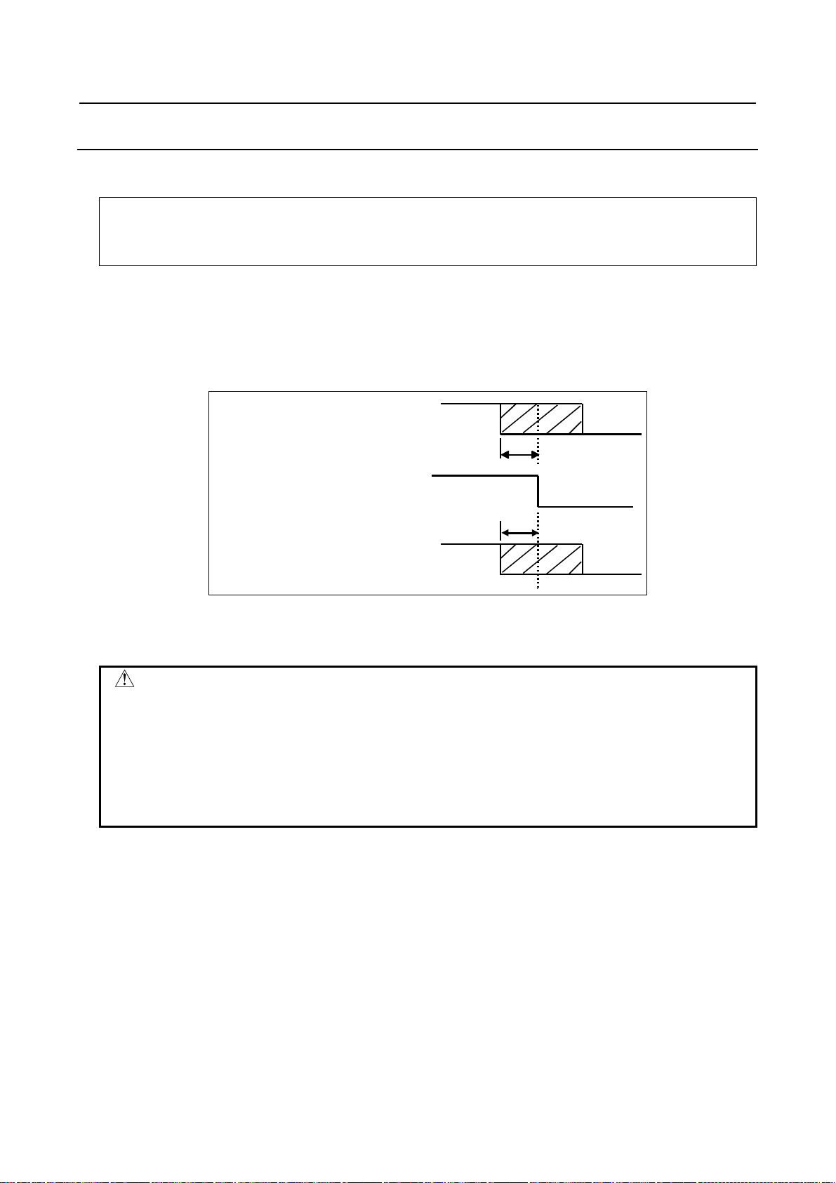
B-64483EN/01 4.POWER SUPPLY CONNECTION
4.2.2 Power-off Sequence
Turn off the power to all the units at the same time, or in the following sequence:
4 Power to the slave I/O units connected via the I/O Link or I/O Link i, the separate detector interface unit, and
the display unit for stand-alone type control unit (24 VDC), power to the control unit (24 VDC)
5 Servo amplifier control power supply (24 VDC), power to the separate detector (scale)
6 Power to the overall machine (AC input)
The expression “the same time” here means that there is no problem even if the power to the units
mentioned in Steps 5 and 6 above is turned off not earlier than 500 ms before the power to the control
unit mentioned in Step 4 above is turned off. If the power to the units mentioned in Steps 5 and 6 is
turned off earlier, alarm information is left in the control unit. In addition, the power to each peripheral
unit mentioned in Step 4 above must be turned off not earlier than 500 ms before the power to the control
unit is turned off. Otherwise, alarm information is left in the control unit.
Power to peripheral units
(including Power Mate i)
ON
OFF
t4
Power to the control unit
Servo amplifier control power supply
Power to the overall machine
ON
OFF
t4
ON
OFF
Fig. 4.2.2
t4:500ms It is meant that the power of interest is turned off not earlier than 500 ms before the
power to the control unit is turned off.
CAUTION
The power to the control unit cannot be turned on or off with peripheral units
supplied with power.
Before turning off the power to the control unit, be sure to turn off the power to
the units (such as slave I/O units connected via the I/O Link i or I/O Link, the I/O
Link i, I/O Link-equipped
i
series servo amplifier, Power Mate i, separate
β
detector I/F units, display units for stand-alone type control unit, servo amplifier
control power, and separate detectors (scale)) connected to the control unit.
- 51 -
Page 72

4.POWER SUPPLY CONNECTION B-64483EN/01
WARNING
It is impossible for the control side to control motors if the power supply is off or
there is no AC input (including power failure). It is necessary for the machine
side to perform any necessary processing.
If the control unit is used to control a vertical axis, for example, provide the motor
with a brake mechanism to prevent a fall along the vertical axis. The brake
should be controlled in such a way that the motor is clamped when the servo has
not be started or when the motor is not supposed to rotate and unclamped only
when it is supposed to rotate. It is common practice to clamp servo motors when
the servo axes cannot be controlled because of the power supply being off or of
a power failure. Even with this common practice, a fall may occur along a
controlled axis before the relay works. So, it is necessary to examine whether
the fall distance poses any problem.
Power-off: Before turning off the control unit power, be sure to apply the
brake to clamp the motor.
Power failure: On detecting a power failure, apply the brake quickly.
Turning off the control unit power results in the servo being
deenergized. So, select a 24 VDC power supply that can maintain
its 24 VDC output for a prolonged time after an AC input
interruption.
- 52 -
Page 73

B-64483EN/01 4.POWER SUPPLY CONNECTION
4.3 CABLE FOR POWER SUPPLY TO CONTROL UNIT
Supply the power to the control unit from a 24 VDC power supply.
Control unit
CPD16A or CPD19A
1
+24V
2
0V
3
GND
Cable
CPD16A or CPD19A
Tyco Electronics
1-178288-3 (housing)
1-175218-5 (contact)
Use terminals that match
24 VDC power.
24VDC power supply
24VDC stabilized power
24VDC ±10%
24VDC power
supply
+24V (1)
0V (2)
Recommended cable: A02B-0124-K830(5m)
(Crimp terminal of size M3 is available on the
24VDC power supply side)
+24V
0V
FG
Interconnect 0V and FG, and
ground them.
In the stand-alone type control unit, a voltage of 24 VDC once input to CPD19A can be branched out
from CPD19B. The terminal arrangement of CPD19B is shown below. With this configuration, it is
necessary for the 24 VDC power supply to supply as much current to CPD19A as the total of that
required by the control unit and that required by external devices connected to CPD19B. The
current-carrying capacity of CPD19B is 1.0 A.
Control unit
CPD19B
1
+24V
2
3
Cable
CPD19B
Tyco Electronics
2-178288-3 (housing)
1-175218-5 (contact)
0V
Use terminals that
match external
devices used.
External device
External
device
+24V (1)
0V (2)
4.4 BATTERIES
A system using this control unit uses batteries in the places listed below. Refer to the FANUC PANEL i
Connection and Maintenance Manual (B-64223EN) for explanations about the batteries used for the
PANEL i. Used batteries must be discarded according to appropriate local ordinances or rules. When
discarding batteries, insulate them by using tape and so forth to prevent the battery terminals from
short-circuiting.
- 53 -
Page 74

4.POWER SUPPLY CONNECTION B-64483EN/01
Use Component connected to battery
Memory backup in the control unit Control unit
Preservation of the current position indicated by the separate absolute
pulse coder
Preservation of the current position indicated by the absolute pulse
coder built into the motor
Separate detector interface unit
Servo amplifier
4.4.1 Battery for Memory Backup in the Control Unit (3 VDC)
Offset data, and system parameters are stored in SRAM in the control unit. The SRAM power is backed
up with the memory backup batteries held in the control unit.
When the voltage of the battery becomes low, alarm message "BAT" blinks on the LCD screen and the
battery alarm signal is output to the PMC. Upon the alarm, replace the battery as soon as possible. The
rough standard for the replacement limit is one week. However, how long the battery lasts after the alarm
varies, depending on the system configuration of interest.
If the voltage of the battery becomes any lower, memory can no longer be backed up. Turning on the
power to the control unit in this state causes system alarm to occur because the contents of memory are
lost. Clear the entire memory and reenter data after replacing the battery.
FANUC thus recommends that the battery be replaced periodically, once a year, regardless of whether a
battery alarm is issued.
The following two kinds of batteries can be used.
• Lithium battery built into the CNC control unit.
• Alkaline dry cell (size D) inserted in an external battery case attached to the control unit.
NOTE
Before shipped from FANUC, the control unit is equipped with a lithium battery
set as default. With this lithium battery, memory contents can be preserved for
one year.
4.4.1.1 Replacing the lithium battery
For LCD-mounted type control unit
Prepare a new lithium battery (ordering code: A02B-0323-K102).
(1) Turn on the power to the machine (control unit). After about 30 seconds, turn off the power.
(2) Take out the lithium battery from the rear of the control unit (by holding the latch of the lithium
battery and pulling it up while unlatching the claw held in the case).
Extract the unit while holding this
portion.
- 54 -
Page 75

B-64483EN/01 4.POWER SUPPLY CONNECTION
(3) Insert a new lithium battery, prepared in advance, into the battery case (by pushing it in until the
claw of the lithium battery fits in the case). Make sure that the claw is latched securely.
Push the unit in until the
claw is latched into the
case.
WARNING
It is likely that the lithium battery may explode unless it is replaced correctly.
Do not use any battery other than the specified one (A02B-0323-K102).
CAUTION
Steps (1) to (3) should be completed within 30 minutes.
Do not leave the control unit without a battery for any longer than the specified
period. Otherwise, the contents of SRAM may be lost.
Before starting battery replacement, save the SRAM contents in a batch. They
can be restored easily even if they are lost.
Refer to the Maintenance Manual (B-64485EN) for explanations about how to
save and restore SRAM contents in a batch.
NOTE
Discard used batteries as “industrial waste” according to the rules and
ordinances of the country where the machine is installed and of the local
government that has jurisdiction over the location of the machine. When
discarding them, insulate the battery terminals with tape or the like to protect
them from short-circuiting.
For stand-alone type control unit
Prepare a new lithium battery (ordering code: A02B-0200-K102).
(1) Turn on the power to the machine (control unit). After about 30 seconds, turn off the power.
(2) Remove the lithium battery from top of the control unit.
First, pull the lithium battery cable to detach the connector. Then, take out the lithium battery from
the battery case.
The battery case is on top of the main board face plate.
(3) After lithium battery replacement, attach the connector.
- 55 -
Page 76

4.POWER SUPPLY CONNECTION B-64483EN/01
WARNING
It is likely that the lithium battery may explode unless it is replaced correctly.
Do not use any battery other than the specified one (A02B-0200-K102).
CAUTION
Steps (1) to (3) should be completed within 30 minutes.
Do not leave the control unit without a battery for any longer than the specified
period. Otherwise, the contents of SRAM may be lost.
Before starting battery replacement, save the SRAM contents in a batch. They
can be restored easily even if they are lost.
Refer to the Maintenance Manual (B-64485EN) for explanations about how to
save and restore SRAM contents in a batch.
NOTE
Discard used batteries as “industrial waste” according to the rules and
ordinances of the country where the machine is installed and of the local
government that has jurisdiction over the location of the machine. When
discarding them, insulate the battery terminals with tape or the like to protect
them from short-circuiting.
4.4.1.2 Replacing commercially available alkaline dry cells (size D)
In place of the built-in lithium battery in the control unit, commercially available alkaline dry cells (size
D) can be used by installing a battery case outside the control unit and inserting the dry cells in the case.
How to connect the battery case to the control unit
For the LCD-mounted type control unit, connect the battery cable (A02B-0323-K103) to the battery case
(A02B-0236-C282). For the stand-alone type control unit, use the battery case (A02B-0236-C281), which
comes with the battery cable attached.
- 56 -
Page 77

B-64483EN/01 4.POWER SUPPLY CONNECTION
×
Example of connecting the battery case to the control unit (LCD-mounted type)
NOTE
1 The battery cable is engaged with its connector using a simple lock mechanism.
Fasten the cable at a length of 500 mm or smaller measured from the connector
with some slack so that the connector will not be disengaged due to the weight
or tension of the cable.
2 Keep the battery cable away from any possible noise source, such as power
wires.
Replacing the alkaline dry cells (size D)
(1) Prepare two new alkaline dry cells (size D).
(2) Turn on the power to the machine (control unit).
(3) Remove the battery case cover.
(4) Replace the batteries, paying careful attention to their orientation.
(5) Replace the battery case cover.
CAUTION
To replace the battery when the power is off, follow the same procedure as that
for the replacement of a lithium battery, described above.
2
Cover
Connection
terminal on the rear
Battery case
Dry cell
Mounting hole
× 4
- 57 -
Page 78

4.POWER SUPPLY CONNECTION B-64483EN/01
4.4.2 Battery for Separate Absolute Pulsecoders (6VDC)
• The absolute Pulsecoder uses a battery because it must hold data on absolute positions. When the
voltage of the batteries for absolute Pulsecoders becomes low, alarm 307 or 306 occurs, with the
following indication in the CNC state display at the bottom of the CNC screen.
Alarm 308 (alarm 2 indicating the voltage of the battery becomes low) :
The indication "APC" blinks in reversed display.
Alarm 307 (alarm indicating the voltage of the battery becomes low) :
The indication "APC" blinks in reversed display.
Alarm 306 (battery zero alarm) :
The indication "ALM" blinks in reversed display.
• When alarm 307 (alarm indicating the voltage of the battery becomes low) occurs, replace the
battery as soon as possible. In general, the battery should be replaced within one or two weeks,
however, this depends on the number of Pulsecoders used.
• When alarm 306 (battery zero alarm) occurs, Pulsecoders are reset to the initial state, in which
absolute positions are not held. Alarm 300 (reference position return request alarm) also occurs,
indicating that reference position return is required.
• In general, replace the batteries periodically within the service life listed below.
- A06B-6050-K061 or D-size alkaline dry cells (LR20) : Two years (for each six-axis
configuration)
- A06B-6073-K001 : Two years (for each three-axis configuration)
- A06B-6114-K504 : One year (for each three-axis configuration)
NOTE
The above values indicate the estimated service life of batteries used with
FANUC absolute Pulsecoders. The actual battery service life depends on the
machine configuration based on, for example, detector types. For details,
contact the machine tool builder.
Replacing batteries
To prevent absolute position information in absolute Pulsecoders from being lost, turn on the machine
power before replacing the battery. The replacement procedure is described below.
<1> Ensure that the power to the servo amplifier is turned on.
<2> Ensure that the machine is in the emergency stop state (the motor is inactive).
<3> Ensure that the DC link charge LED of the servo amplifier is off.
<4> Detach the old batteries and attach new ones.
- 58 -
Page 79
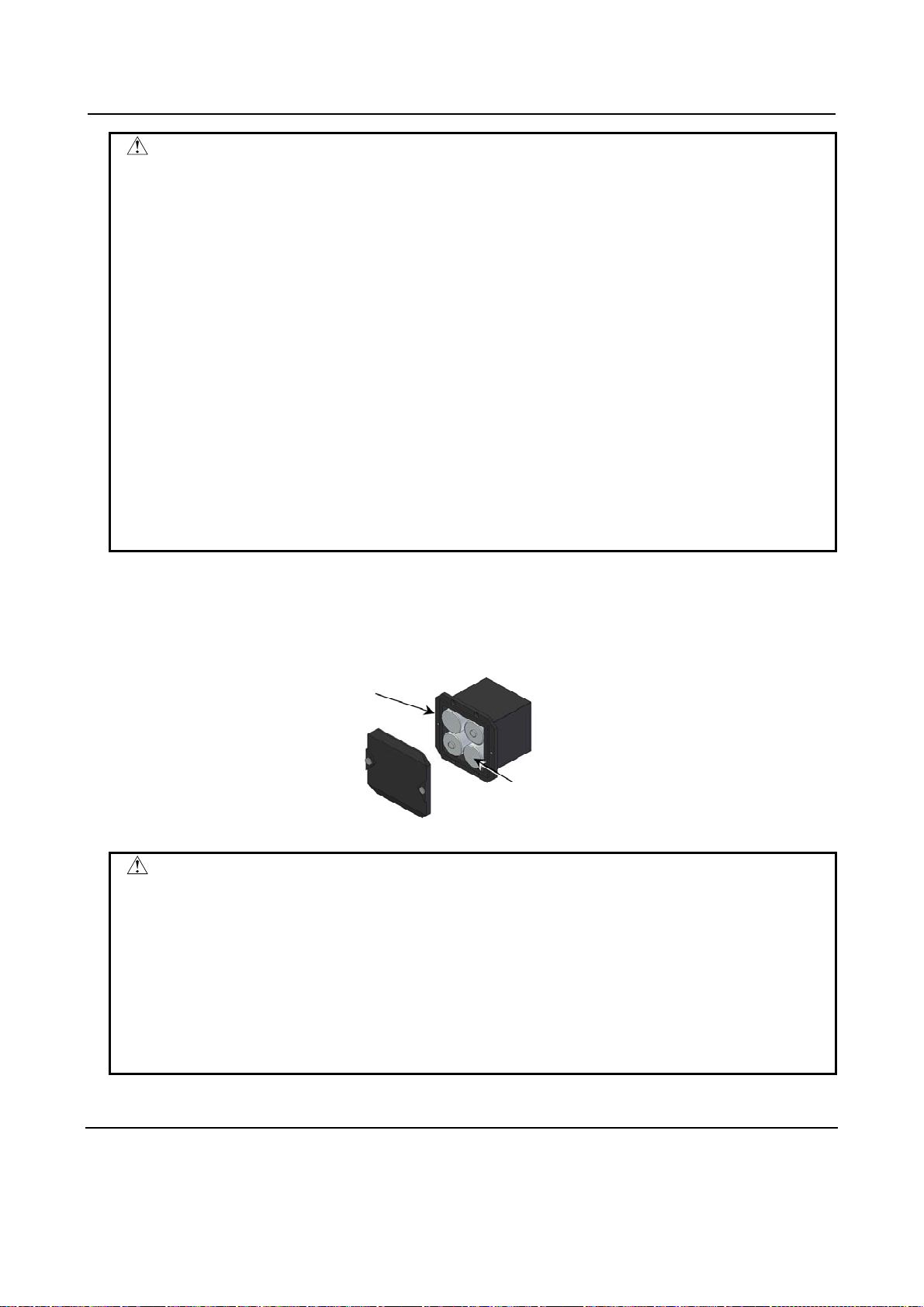
B-64483EN/01 4.POWER SUPPLY CONNECTION
A
WARNING
The absolute Pulsecoder of each of the
•
series servo motors (
i
S0.4 to
β
i
S22) has a built-in backup capacitor.
β
i
/
S series servo motors and the
α
α
i
S
β
i
Therefore, even when the power to the servo amplifier is off and the batteries
are replaced, reference position return is not required if the replacement
completes within less than 10 minutes. Turn the power on and replace the
batteries if the replacement will take 10 minutes or more.
To prevent electric shock, be careful not to touch metal parts in the power
•
magnetics cabinet when replacing the batteries.
Because the servo amplifier uses a large-capacitance electrolytic capacitor
•
internally, the servo amplifier remains charged for a while even after the power is
turned off. Before touching the servo amplifier for maintenance or other
purposes, ensure your safety by measuring the residual voltage in the DC link
with a tester and confirming that the charge indication LED (red) is off.
Be sure to replace the batteries with specified ones. Pay attention to the battery
•
polarity. If a wrong type of battery is used or a battery is installed with incorrect
polarity, the battery may overheat, blow out, or catch fire, or the absolute
position information in the absolute Pulsecoders may be lost.
Ensure that the battery connector is inserted in the correct position.
•
How to insert batteries into the battery case
Use the following procedure to replace the batteries in the battery case.
<1> Loosen the screws on the battery case and detach the cover.
<2> Replace the batteries in the case (pay attention to the polarity).
<3> Attach the cover to the battery case.
Battery case (with a cover)
06B-6050-K060
Batteries
Four A06B-6050-K061 batteries or
D-size alkaline dry cells
CAUTION
Four D-size alkaline dry cells (LR20) that are commercially available can be
•
used as batteries. A set of four A06B-6050-K061 batteries is optionally available
from FANUC.
Replace all the four batteries with new ones. If old and new batteries are mixed,
•
the absolute position information in the absolute Pulsecoders may be lost.
When connecting batteries, pay due attention to their polarity. If they are
•
connected in reverse polarity, it is likely that they may get hot, explode, or catch
fire. In addition, it is also likely that information on absolute positions may be lost
from the absolute Pulsecoder.
4.4.3 Battery for Absolute Pulse Coder Built into the Motor (6VDC)
The battery for the absolute pulse coder built into the motor is installed in the servo amplifier.
Explanations about how to connect and replace the battery, refer to the maintenance manual for the servo
amplifier in use.
- 59 -
Page 80

5.CONNECTION TO CNC PERIPHERALS B-64483EN/01
5 CONNECTION TO CNC PERIPHERALS
5.1 CONNECTION BETWEEN THE LCD-MOUNTED TYPE
CONTROL UNIT AND MDI UNIT
5.1.1 Connection Diagram
LCD-mounted type control unit
CA55
MDI cable
CK27
MDI unit
- 60 -
Page 81

B-64483EN/01 5.CONNECTION TO CNC PERIPHERALS
A
A
5.1.2 Connection with the MDI Unit
Control unit
CK27
Recommended MDI unit
connector
PCR-E20FA(Honda T s ushin Kogyo)
FI30-20S(Hirose Electric)
FCN-247J020-G/E(FUJITSU
COMPONENT)
52622-2011(Molex)
CK27
02B-0236-K813(45cm)
02B-0236-K814(1.5m)
, Maximum cable length : 20m)
NOTE
For MDI cable connector mating on the CA55 side, a simple lock mechanism is
employed. Ensure that a load greater than 1 kg is not applied to the connectors.
Moreover, clamp the cable so that excessive force is not applied due to
vibration. However, shielding and clamping are not required for a cable of up to
50 cm.
- 61 -
Page 82

5.CONNECTION TO CNC PERIPHERALS B-64483EN/01
A
A
A
A
5.1.3 Key Layout of MDI Unit
For Lathe (T series)
- Standard MDI unit (ONG keys)
Case shift key
Shift key
UX key
CTRL key
LT key
TAB key
Reset key Help key
ddress/numeric keys
Edit keys
Cancel (CAN) key
Input key
Page change keys
- Small MDI unit (ONG keys)
Function keys
Page change keys
Cursor keys Function keys
ddress keys/Numer ic keys
Cancel (CAN) key
Input key
Shift key
Help key
Reset key
Edit keys
Cursor keys
- 62 -
Page 83

B-64483EN/01 5.CONNECTION TO CNC PERIPHERALS
A
AUX
A
A
For Machining center (M series)
- Standard MDI unit (ONG keys)
Case shift key
Shift key
key
CTRL key
LT key
TAB key
Reset key Help key
ddress/numeric keys
Edit keys
Cancel (CAN) key
Input key
Page change keys
- Small MDI unit (ONG keys)
Function keys
Page change keys
Cursor keys Function keys
ddress/numeric keys
Cancel (CAN) key
Input key
Shift key
Help key
Reset key
Edit keys
Cursor keys
- 63 -
Page 84

5.CONNECTION TO CNC PERIPHERALS B-64483EN/01
A
A
A
Common to lathe system / machining center system
- Standard MDI unit (QWERTY keys)
Help key
Reset key
Function keys
Address keys
Case shift key
AUX key
CTRL key
ALT key
TAB key
Page change keys
Cursor keys
- Standard MDI unit (QWERTY type B keys)
Help key
Function keys
Case shift key
ddress keys
Reset key
Edit keys
Cancel (CAN) key
Edit keys
Numeric keys
Shift key
Input key
Numeric keys
CTRL key
LT key
TAB key
UX key
Shift key
Cursor keys
Page change keys
Input key
Cancel (CAN) key
- 64 -
Page 85

B-64483EN/01 5.CONNECTION TO CNC PERIPHERALS
y
A
5.2 CONNECTION BETWEEN THE STAND-ALONE TYPE
CONTROL UNIT AND DISPLAY UNIT AND BETWEEN THE
DISPLAY UNIT AND MDI UNIT
5.2.1 Overview
This subsection describes connection between the stand-alone type control unit and display unit. It also
describes connection between the display unit and MDI unit.
5.2.2 With the 10.4” Display Unit
Stand-alone
type control
unit
COP21
Optical fiber cable
Display unit
COP21B
External power suppl
24VDC±10%
CP1A
CP1B
CA55
MDI unit
CK27
- 65 -
Page 86

5.CONNECTION TO CNC PERIPHERALS B-64483EN/01
Connection to the control unit and power supply
An optical fiber cable is used to make the connection between the control unit and display unit.
For details of the optical fiber cable, see Appendix D.
Supply the power to the display unit from an external 24 VDC power supply.
Display unit
CP1A
1
+24V
2
0V
3
GND
Cable
CP1A
Tyco Electronics
1-178288-3 (housing)
1-175218-5 (contact)
+24V (1)
0V (2)
Recommended cable : A02B-0124-K830(5m)
(Crimp terminal of size M3 is available on the 24VDC power supply side)
Use a terminal available
with the 24 VDC power
supply.
Part of the 24 VDC power input to CP1A can be taken out from CP1B by branching. CP1B connection is
as shown below. In this case, the rating of the external 24 VDC power supplied to CP1A must be the sum
of the power consumed within the display unit and that supplied to external equipment via CP1B. Up to
1.0 A can be supplied to the external equipment.
24VDC power supply
24VDC stabilized power
24VDC ±10%
24VDC power supply
+24V
0V
FG
Make a jumper between 0 V
and FG to connect ground.
Display unit
CP1B
1
+24V
2
3
Cable
CP1B
Tyco Electronics
2-178288-3 (housing)
1-175218-5 (contact)
0V
Use terminals that match
external devices used.
+24V (1)
0V (2)
External device
External
device
Connection to the MDI unit
For the connection between the connector (CA55) on the display unit and that (CK27) on the MDI unit,
see Section 5.1, “Connection between the LCD-mounted Type Control Unit and MDI Unit”.
With the LCD-mounted type control unit, the connector (CA55) is located on the back of the control unit.
With the stand-alone type control unit, the connector is located on the back of the display unit.
- 66 -
Page 87

B-64483EN/01 5.CONNECTION TO CNC PERIPHERALS
5.2.3 With Two Display Units
5.2.3.1 Each connection
Stand-alone type
control unit
24V-IN (CPD 19A)
DISPLAY (COP21A)
External
power supply
24VDC±10%
Optical fiber cable
24-V power
cable
External
power supply
24VDC±10%
External
power supply
24VDC±10%
1st display unit
CP1A
CP1B
CA55
COP21B
JA73
CA103
Video cable
between units
CA103
JA73
CA55
CP1A
CP1B
MDI
cable
MDI cable
between units
MDI
cable
MDI unit
CK27
MDI unit
CK27
2nddisplay unit
Connection to the control unit, between display units, and to the power
supply
An optical fiber cable is used to make the connection between the control unit and 1st display unit. Video
and MDI cables between units are used to make the connection between the 1st and 2nd display units. For
details of the optical fiber cable, see Appendix D.
Connect cables between units as follows. The maximum length of a cable between the 1st and 2nd display
units is 50 m.
- 67 -
Page 88

5.CONNECTION TO CNC PERIPHERALS B-64483EN/01
Connection of the MDI cable between units
1st display unit 2nd display unit
JA73
PCR-E20MDA
1 *KEY00 11 *KEY01
2 *KEY02 12 *KEY03
3 *KEY04 13 *KEY05
4 *KEY06 14 *KEY07
5 *COM00 15 *COM01
6 *COM02 16 *COM03
7 *COM04 17 *COM05
8 *COM06 18 *COM07
9 *COM08 19 *COM09
10 *COM10 20 *COM11
JA73
PCR-E20MDA
1 *KEY00 11 *KEY01
2 *KEY02 12 *KEY03
3 *KEY04 13 *KEY05
4 *KEY06 14 *KEY07
5 *COM00 15 *COM01
6 *COM02 16 *COM03
7 *COM04 17 *COM05
8 *COM06 18 *COM07
9 *COM08 19 *COM09
10 *COM10 20 *COM11
Cable
*KEY00
*KEY02
*KEY04
*KEY06
*COM00
*COM02
*COM04
*COM06
*COM08
*COM10
*KEY01
*KEY03
*KEY05
*KEY07
*COM01
*COM03
*COM05
*COM07
*COM09
*COM11
1
2
3
4
5
6
7
8
9
10
11
12
13
14
15
16
17
18
19
20
Shield
Ground plate
1
*KEY00
2
*KEY02
3
*KEY04
4
*KEY06
5
*COM00
6
*COM02
7
*COM04
8
*COM06
9
*COM08
10
*COM10
11
*KEY01
12
*KEY03
13
*KEY05
14
*KEY07
15
*COM01
16
*COM03
17
*COM05
18
*COM07
19
*COM09
20
*COM11
Ground plate
Ground the shield of
the cable near each
display unit.
Recommended cable:
A02B-0323-K865 (50m)
A02B-0303-K848 (30m)
A02B-0303-K845 (20m)
A02B-0303-K846 (10m)
A02B-0303-K847 (5m)
Recommended cable–side connectors (JA73):
PCR-E20FA (Honda Tsushin Kogyo Co., Ltd.)
FI30-20S (Hirose Electric Co., Ltd.)
Recommended wire specification:
A66L-0001-0284#10P(#28AWG × 10 pairs, maximum cable length: 50m)
- 68 -
Page 89

B-64483EN/01 5.CONNECTION TO CNC PERIPHERALS
Connection of the video cable between units
If a severe noise environment is expected or the length of the video cable between units is longer than 30 m, be sure to
mount a ferrite core (A02B-0323-K869) between the 2nd display unit and ground plate on the 2nd display unit.
1st display unit
CA103
DV2R024N11
1 DVI2M 9 DVI1M 17 DVI0M
2 DVI2P 10 DVI1P 18 DVI0P
3 0V 11 0V 19 0V
4 *BLOFFP 12 *RGBENM 20
5 *BLOFFM 13 *RGBENP 21
6 14 22 0V
7 15 0V 23 DVICK1P
8 0V 16 24 DVICK1M
Cable
DVICKP
DVICKM
*BLOFFP
*BLOFFM
*RGBENM
*RGBENP
(Connector frame)
DVI2M
DVI2P
0V
DVI1M
DVI1P
0V
DVI0M
DVI0P
0V
0V
0V
0V
1
2
3
9
10
11
17
18
19
23
24
22
4
5
12
13
15
8
Shield
2nd display unit
CA103
DV2R024N11
1 DVI2M 9 DVI1M 17 DVI0M
2 DVI2P 10 DVI1P 18 DVI0P
3 0V 11 0V 19 0V
4*BLOFFP12*RGBENM 20
5 *BLOFFM 13 *RGBENP 21
6 14 22 0V
7 15 0V 23 DVICK1P
80V 16 24 DVICK1M
1
DVI2M
2
DVI2P
3
0V
9
DVI1M
10
DVI1P
11
0V
17
DVI0M
18
DVI0P
19
0V
23
DVICKP
24
DVICKM
22
0V
4
*BLOFFP
5
*BLOFFM
12
*RGBENM
13
*RGBENP
15
0V
8
0V
(Connector frame)
Ground plate
Recommended cable:
A02B-0323-K860 (50m)
A02B-0303-K843 (30m)
A02B-0303-K840 (20m)
A02B-0303-K841 (10m)
A02B-0303-K842 (5m)
Recommended cable–side connectors (CA103):
DV2P024M11 (connector)(Japan Aviation Electronics Industry)
D045-51839 (housing)(Japan Aviation Electronics Industry)
Recommended wire specification:
A66L-0001-0511 (Maximum cable length: 50m)
Ground plate
Ground the shield of the cable near each
display unit.
When connecting the video cable between units to each display unit, fix the
cable with the cable support plate attached with the unit.
- 69 -
Page 90

5.CONNECTION TO CNC PERIPHERALS B-64483EN/01
Supply the power to the display unit from an external 24 VDC power supply.
Display unit
CP1A(X)
1
+24V
2
0V
3
GND
Cable
CP1A(X)
Tyco Electronics
1-178288-3 (housing)
1-175218-5 (contact)
+24V (1)
0V (2)
Recommended cable : A02B-0124-K830(5m)
(Crimp terminal of size M3 is available on the 24VDC power supply side)
Use a terminal available with
the 24 VDC power supply.
To share a power supply between the 1st and 2nd display units, see the figure below.
1st display unit
24VDC power supply
24VDC stabilized power
24VDC ±10%
24VDC power supply
+24V
0V
FG
Make a jumper between 0 V
and FG to connect ground.
2nd display unit
CP1B (Y)
1 +24V
2 0V
3
Cable
CP1B (Y)
Tyco Electronics
2-178288-3 (housing)
1-175218-5 (contact)
+24V (1)
0V(2)
CP1A (X)
1 +24V
20V
3
CP1A (X)
Tyco Electronics
1-178288-3 (housing)
1-175218-5 (contact)
+24V (1)
0V(2)
NOTE
For power-on and -off timing, see Section 4.2, “TURNING ON AND OFF THE
POWER TO THE CONTROL UNIT”.
Make connection so that 24 VDC ±10% power is also supplied to the 2nd display
unit in the same way as for the 1st display unit.
Connection to the MDI unit
For the connection between the connector (CA55) on the display unit and that (CK27) on the MDI unit,
see Section 5.1, “Connection between the LCD-mounted Type Control Unit and MDI Unit”.
With the LCD-mounted type control unit, the connector (CA55) is located on the back of the control unit.
With the stand-alone type control unit, the connector is located on the back of the display unit.
NOTE
Be sure to use two MDI units of the same type when required.
- 70 -
Page 91

B-64483EN/01 5.CONNECTION TO CNC PERIPHERALS
5.2.3.2 Installing the display unit
Note)
60mm
50mm 50mm
NOTE
100 mm (max) when the connector of the MDI cable between units is
spring-fixed or 60 mm (max) when it is screw-fixed.
- 71 -
Page 92

5.CONNECTION TO CNC PERIPHERALS B-64483EN/01
5.2.4 With the 15” Display Unit
Stand-alone
type control
unit
COP21A
Optical fiber cable
15” display unit
COP21M
External power supply
24VDC±10%
CPD18
CA55
MDI unit
CK27
Connection to the control unit and power supply
An optical fiber cable is used to make the connection between the control unit and display unit.
For details of the optical fiber cable, see Appendix D.
Supply the power to the display unit from an external 24 VDC power supply.
Display unit
CPD18 (Y)
1
2
3
+24V
0V
GND
24VDC power supply
24VDC stabilized power
24VDC ±10%
Cable
CPD18 (Y)
Tyco Electronics
1-178288-3 (housing)
1-175218-5 (contact)
+24V (1)
0V (2)
Recommended cable : A02B-0124-K830(5m)
(Crimp terminal of size M3 is available on the 24VDC power supply side)
Use a terminal available with
the 24 VDC power supply.
+24V
0V
FG
Make a jumper between 0 V
and FG to connect ground.
24VDC power supply
Connection to the MDI unit
For the connection between the connector (CA55) on the display unit and that (CK27) on the MDI unit,
see Section 5.1, “Connection between the LCD-mounted Type Control Unit and MDI Unit”.
With the LCD-mounted type control unit, the connector (CA55) is located on the back of the control unit.
With the stand-alone type control unit, the connector is located on the back of the display unit.
- 72 -
Page 93

B-64483EN/01 5.CONNECTION TO CNC PERIPHERALS
5.2.5 With the Display Unit for Automotive
5.2.5.1 Each connection
Control unit
24V-IN(CPD19A)
DISPLAY(COP21A)
I/O Link (JD51A)
I/O Link device
I/O Link (JD1B)
I/O Link (JD1A)
Disp la y unit for au tomo tiv e
HSSB (COP21M)
+24V (CPD18)
Card slot
I/O Link (JD1A)
(Note 1)
External power
supply
24VDC±10%
I/O Link device
I/O Lin k (J D 1 B)
(Note 1)
USB mouse
USB keyboard
USB mouse
USB keyboard
NOTE
1 The I/O Link interface is optional.
2 On the display unit for automobile manufacturers, the MDI unit is built onto the
front panel.
- 73 -
Page 94
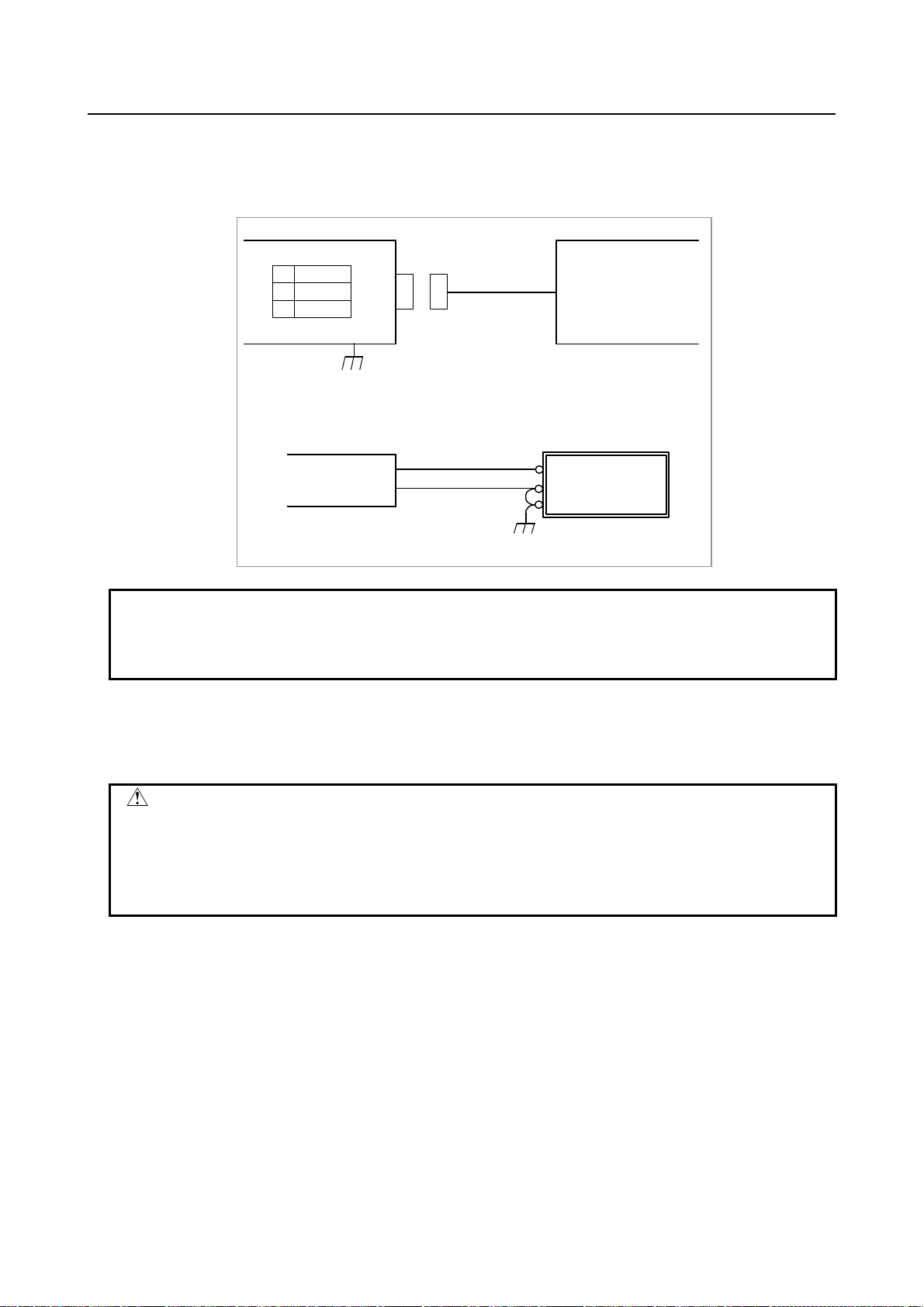
5.CONNECTION TO CNC PERIPHERALS B-64483EN/01
Connection to the control unit and power supply
An optical fiber cable is used to make the connection between the control unit and display unit.
For details of the optical fiber cable, see Appendix D.
Supply the power to the display unit from an external 24 VDC power supply.
Display unit
CPD18 (Y)
1
+24V
2
0V
3
GND
Cable
CPD18 (Y)
Tyco Electronics
1-178288-3 (housing)
1-175218-5 (contact)
+24V (1)
0V (2)
Recommended cable : A02B-0124-K830(5m)
(Crimp terminal of size M3 is available on the 24VDC power supply side)
Use a terminal available with
the 24 VDC power supply.
24VDC power supply
24VDC stabilized power
24VDC ±10%
24VDC power supply
+24V
0V
FG
Make a jumper between 0 V
and FG to connect ground.
NOTE
1 Keep the power cable away from other cables connected to the display unit.
2 Turn the power to the display unit on or off within ±100 ms after the power to the
control unit is turned on or off.
USB port
The display unit for automobile manufacturers has two USB ports on its front panel. These USB ports can be
used to connect a USB memory, USB mouse, and USB keyboard.
CAUTION
1 While the control unit is accessing the USB memory, do not turn the power to the
control unit off or remove the USB memory.
2 Close the cover of a USB port when the USB port is not used.
3 The maximum USB power supply (USB_5V) current for the two USB ports is 500
mA in total.
Connection of vertical soft keys to the I/O Link
As the case of the Display Unit for Automotive has vertical soft keys with I/O Link option, the control unit
can directly read the signals from vertical soft keys via the I/O Link. For the connection of the I/O Link, see
Subsection 7.2.1.
- 74 -
Page 95

B-64483EN/01 5.CONNECTION TO CNC PERIPHERALS
Address assignment on the I/O Link for vertical soft keys
Allocate a 2-byte input area on the I/O Link. (Assignment name: /2)
When the start DI address assigned for a soft key is Xm, the assignment is shown below.
7 6 5 4 3 2 1 0
Xm+0 L8 L7 L6 L5 L4 L3 L2 L1
Xm+1 R8 R7 R6 R5 R4 R3 R2 R1
L1
L2
L3
L4
L5
L6
L7
L8
R1
R2
R3
R4
R5
R6
R7
R8
5.2.5.2 Installing the display unit
The display unit for automobile manufacturers requires the following clearances around it.
A: Clearance required for routing of cables
B: Clearance required for air to move easily
80
B
Rear
A
A
B
90
- 75 -
Page 96

5.CONNECTION TO CNC PERIPHERALS B-64483EN/01
5.3 CONNECTION WITH INPUT/OUTPUT DEVICES
5.3.1 Overview
An input/output device is used to enter information such as control unit programs and parameters from an
external device to the control unit, or to output information from the control unit to an external device.
The input/output devices usable with this control unit include Handy File.
The interface of the input/output devices electrically conforms to RS232-C, so that a connection can be
made with a device that has an RS232-C interface.
The tables below indicate the serial ports of this control unit.
Port name Interface location
1CH (JD56A) Main control unit
2CH (JD36A) Main control unit Note
The serial ports of the 15” LCD-mounted type control unit are as listed in the table below, however.
Port name Interface location
1CH (JD56A) Main control unit
2CH (JD54) Main control unit Note
NOTE
When a touch panel is used, this serial port is used for touch panel
communication on the control unit side, so that this port cannot be used as a
general-purpose port.
5.3.2 Connecting I/O Devices
R232C-1
JD56A
This figure shows an
example of connection
for the LCD-mounted
type control unit.
R232C-2
JD36A/JD54
Punch panel
External I/O device
- 76 -
Page 97

B-64483EN/01 5.CONNECTION TO CNC PERIPHERALS
NOTE
This interface is the RS232-C interface on the control unit side.
For these devices, the RS232-C interface on the control unit is used for the
following cases:
Ladder monitoring, storing, or loading using FANUC LADDER III
•
DNC operation via RS232-C, external I/O device control
•
Input/output of parameters and programs by using the control unit screen
•
display function
5.3.3 RS232-C Serial Port
Control unit
JD56A, JD36A/JD54
FI80-20P, DF1R020WB1
(PCR-EV20MDT)
RD
10
1
0V
2
DR
3
0V
4
CS
5
0V
6
CD
7
8
0V
(*)
9
+24V
11
12
13
14
15
16
17
18
19
20
SD
0V
ER
0V
RS
0V
(*)
(+5V)(*)
+24V
(+5V)(*)
>„
>„
<
Relay connector
(DBM-25S)
1
10
11
12
13
FG
2
SD
RD
3
RS
4
5
CS
DR
6
SG
7
8
CD
9
14
15
16
17
18
19
20
21
22
23
24
25
ER
+24V
NOTE
1 Do not connect anything to those pins for which signal names are not indicated.
2 Pins 18 and 20 (+5V) are provided for touch channel connection.
3 The upper manufacturer and model on the control unit side are for the
LCD-mounted type.
The lower manufacturer and model in parentheses are for the stand-alone type.
4 Do not connect anything to pins 6 and 8 of JD54 on the 15” LCD-mounted type
control unit because these signals are reserved.
- 77 -
Page 98
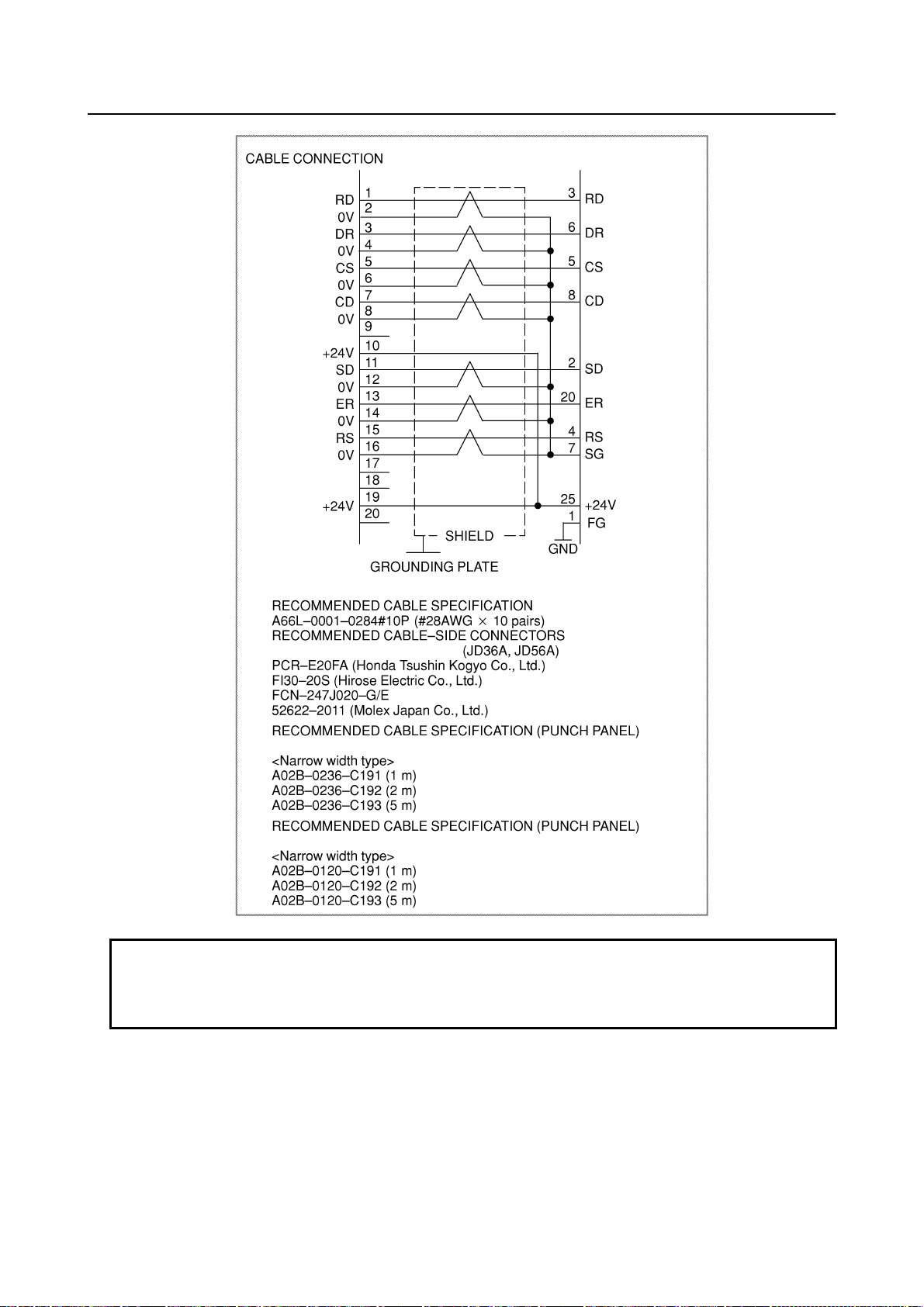
5.CONNECTION TO CNC PERIPHERALS B-64483EN/01
(FUJITSU COMPONENT)
For LCD-mounted type
For stand-alone type
NOTE
1 Do not connect anything to those pins for which signal names are not indicated.
2 Recommended cable-side connector FI30-20S (manufactured by Hirose Electric)
cannot be used for the stand-alone type.
- 78 -
Page 99

B-64483EN/01 5.CONNECTION TO CNC PERIPHERALS
A
5.3.4 RS232-C Interface Specification
RS232-C Interface signals
Generally signals as follows are used in RS232-C interface.
Control unit
Output
SD (Send data)
Input
RD (Receive data)
RS (Request to Send)
When CS is not used short CS
and RS.
CS (Enable to send)
ER (Ready)
DR (Data set ready)
CD (Check data)
SG (Signal ground)
FG (Frame ground)
Fig. 5.3.4 RS232-C interface
Signal description of RS232-C interface
Signal I/O Description
SD Output Sending data
RD Input Receiving data
Start bit
Stop bits
When DR is not used
short DR and ER.
lways short ER and
CD.
(When ISO code 0 is sent)
RS Output Sending
request
CS Input Sending
permitted
This signal is set to on when control unit starts sending data and is turned
off when transmission ends.
When both this signal and the DR signal are set, the control unit can send
data. If I/O device processing is delayed by a punching operation, etc.,
control unit data sending can be stopped by turning off this signal after
sending two characters, including the data being sent currently. If this signal
will not be used, make sure to strap this signal circuit to the RS signal
circuit.
DR Input Data set ready When I/O device is ready to operate, this signal is set. This signal should
usually be connected to the signal indicating I/O device power supply being
on. (ER signal
(Note)
of I/O device). See Note below.
The control unit transfers data when this signal is set. If the signals turned
off during data transfer, alarm 086 is issued. If the DR signal will not be
used, make sure to strap this signal circuit to the ER signal circuit.
ER Output Control unit
ready to
This signal is set when the control unit is ready to operate. External device
should regard the SD signal as being significant when the ER signal is set.
operation
CD Input Signal
Condition
Since this signal is not used in connections with I/O device, the signal circuit
must be strapped, inside the connecting cable, to the ER signal circuit.
SG Signal grounding
FG Frame grounding
- 79 -
Page 100

5.CONNECTION TO CNC PERIPHERALS B-64483EN/01
NOTE
Signal on/off state is defined as follows;
-3V or lower +3V or higher
Function OFF ON
Signal Condition Marking Spacing
Transmission Method of RS232-C interface
- Start-stop
Generally, two transmission methods are available at the serial interface. This control unit uses the
start-stop method.
NOTE
Start-stop method:
With this method, start and stop signals are output before and after each data
bit.
One character in start-stop
b1 b2 b3 b4 b5 b6 b7 b8
Start bit Data bit
(8 bits including one parity bit)
Stop bits
(2 bits)
- Codes
Transmission codes are as follows:
(1) EIA code and Control codes DC1 to DC4.
(2) ISO code and Control codes DC1 to DC4 (Optional ISO code input is necessary.)
The connected I/O device must be able to recognize the following control codes, sent from control
unit.
Control code 8 7 6 5 4 3 2 1
DC1 Tape reader start
DC2 Tape punch designation
DC3 Tape reader stop
DC4 Tape punch release
○
○
○
○
○
○
○
○
○
○
○ ○
○
NOTE
The listed control codes are used for both EIA and ISO.
In this interface, control codes DC1 to DC4 are used.
(a) Control unit can control I/O device by issuing codes DC1 to DC4.
(b) If processing is delayed at the I/O device (when the control unit outputs data)
(i) External device can temporarily stop control unit data output by using the control unit's
CS signal. Data output stops within two characters including a currently transmitting
character when CS OFF signal is input to control unit. When CS signal is turned on again,
data transmission start.
(ii) If control code DC3 is input to control unit, control unit stops data output within ten
characters. When control code DC1 is input to control unit, control unit starts sending data
again.
○
- 80 -
 Loading...