

OPERATION MANUAL
X S
ERIES
PR 5220
E
THERNET
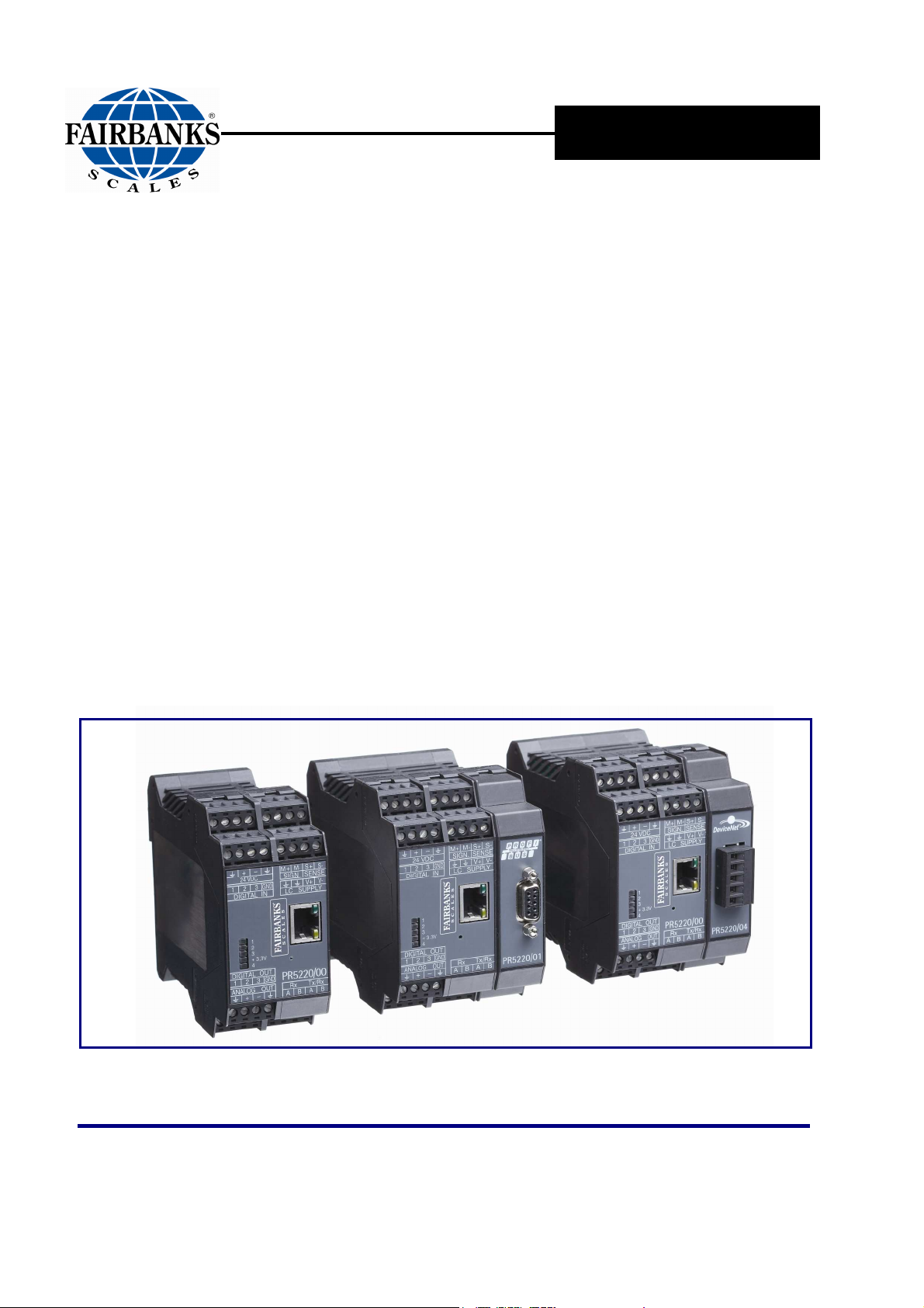
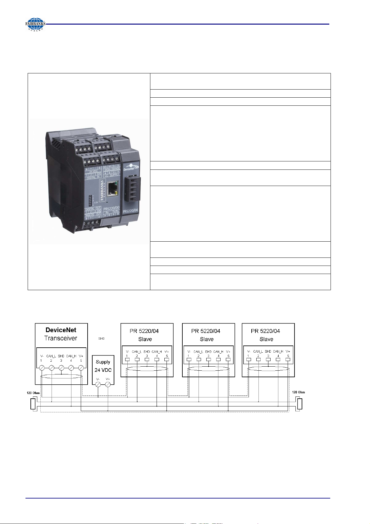
PR 5220/00 Ethernet Transmitter
PR 5220/01 Ethernet Transmitter with Profibus
PR 5220/04 Ethernet Transmitter with DeviceNet
T
RANSMITTER
© 2008-2011 by Fairbanks Scales, Inc.
All rights reserved
Revision 2 05/11
51209


Amendment Record
X Series
PR 5220 Ethernet Transmitter
Document 51209
Distributed by Fairbanks Scales Inc.
821 Locust
Kansas City, Missouri 64106
Created 10/2008
Revision 1 12/2008 Documentation Release
Revision 2 05/2011 Corrected Table of Contents
Disclaimer
Every effort has been made to provide complete and accurate information in this
manual. However, although this manual may include a specifically identified warranty
notice for the product, Fairbanks Scales makes no representations or warranties with
respect to the contents of this manual, and reserves the right to make changes to this
manual without notice when and as improvements are made.
Fairbanks Scales shall not be liable for any loss, damage, cost of repairs, incidental
or consequential damages of any kind, whether or not based on express or implied
warranty, contract, negligence, or strict liability arising in connection with the design,
development, installation, or use of the scale.
© Copyright 2008-2011
This document contains proprietary information protected by copyright. All rights are
reserved; no part of this manual may be reproduced, copied, translated or transmitted
in any form or by any means without prior written permission of the manufacturer.

Table of Contents
1 Safety Information ........................................................................................................ 9
1.1 INTENDED USE ..................................................................................................................... 9
1.2 INITIAL INSPECTION ............................................................................................................ 9
1.3 BEFORE COMMISSIONING .................................................................................................. 9
1.3.1 Installation 9
1.3.2 Electrostatically Sensitive Components 9
1.3.3 Protective Earth 10
1.3.4 Supply Voltage Connection 10
1.3.5 Failure and Excessive Stress 10
1.3.6 Fuse 10
1.3.7 EMC-Compliant Installation 10
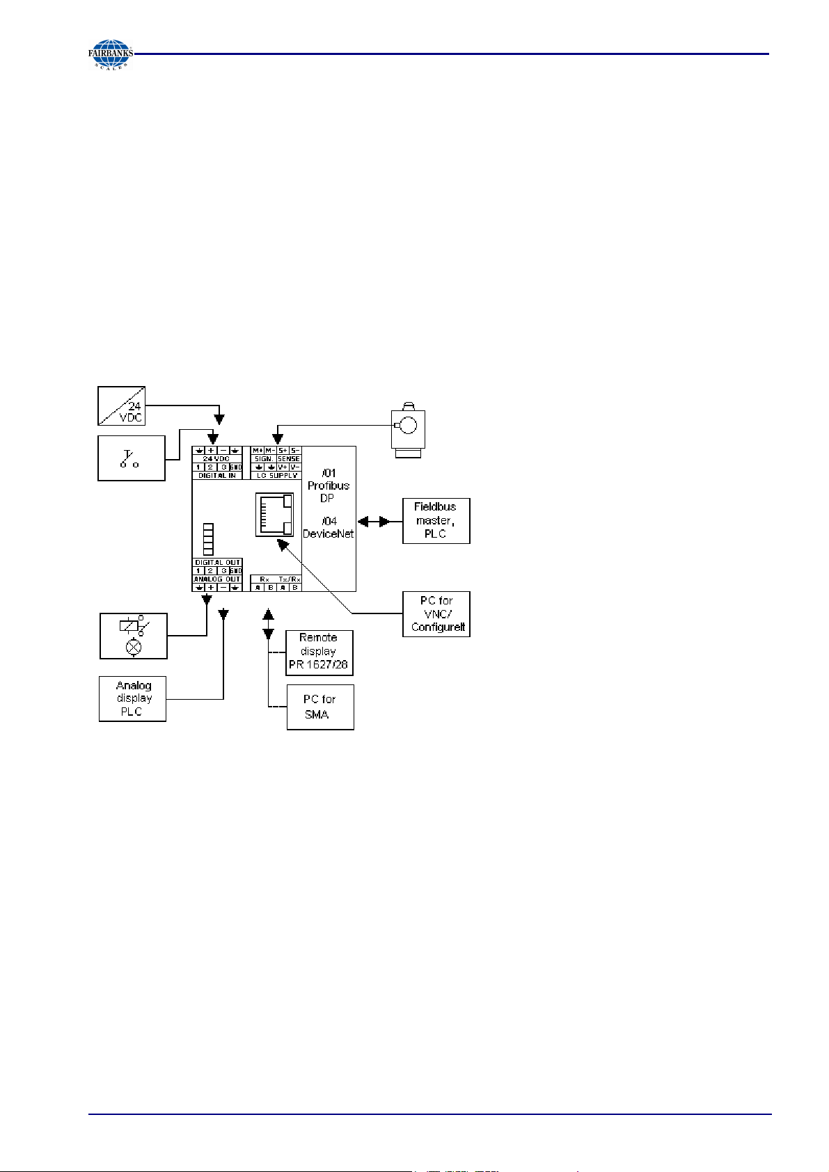
2 PR 5220 Ethernet Transmitter Series ........................................................................ 11
2.1 THE TRANSMITTER VERSIONS ......................................................................................... 11
2.1.1 PR 5220/00 Version 11
2.1.2 PR 5220/01 Profibus 11
2.1.3 PR 5220/04 DeviceNet 11
2.2 OVERVIEW OF THE INSTRUMENT .................................................................................... 12
2.3 LABEL ON THE HOUSING .................................................................................................. 12
2.4 HOUSING DIMENSIONS ..................................................................................................... 13
2.5 OPERATION USING THE VNC PROGRAM ........................................................................ 14
2.5.1 Status Symbols 14
2.5.2 Transmitter Keys 14
2.5.3 Navigation Keys, Other Keys 14
2.5.4 Selection Using the Navigation Keys 15
2.5.5 System Messages during Input 16
3 Installing the Instrument ............................................................................................ 17
3.1 NETWORK PORT ................................................................................................................ 18
3.2 CONNECTIONS ................................................................................................................... 19
3.2.1 Load Cell Connection 19
3.2.2 Connection Using 6-Wire Technology 19
3.2.3 Connection of a Load Cell in 4-Wire Technology 19
3.2.4 Connecting PR 6221 Load Cells 20
3.2.5 External Load Cell Supply 20
3.2.6 Connection via PR 1626/60 20
3.2.7 RS-422/485 Interface 21
3.2.8 Analog Output 22
3.2.9 3 Optocoupler Inputs 23
3.2.10 3 Optocoupler Outputs 24
3.2.11 Profibus Interface (PR 5220/01 only) 25
3.2.12 DeviceNet Interface (PR 5220/04 only) 26
4 Controls ....................................................................................................................... 27
4.1 STATUS INDICATOR LEDS ................................................................................................ 27
4.1.1 Weight error status: 27
5 Commissioning ........................................................................................................... 28
5.1 DATA BACKUP/POWER FAILURE ..................................................................................... 28
5.1.1 CAL Switch 28
5.1.2 Factory Settings 28
05/11 3 51209 Revision 2

Table of Contents
5.2 SWITCHING ON THE INSTRUMENT .................................................................................. 29
5.2.1 Resetting the Instrument, Activating 'DHCP' 29
5.2.2 Searching the Instrument in the Network Using 'IndicatorBrowser' 30
5.3 OPERATION USING A PC .................................................................................................. 30
5.3.1 Operation Using the VNC Program 30
5.3.2 Operation Using Internet Browser 31
5.3.3 INFO Function 32
5.3.4 Setup Function (VNC) 33
5.3.5 Setup Menu 33
5.3.6 Calibration Menu 34
5.4 CALIBRATION .................................................................................................................... 35
5.4.1 Displaying Calibration Data 35
5.4.2 Increased Resolution (10-Fold) 35
5.4.3 Selecting the Calibration Mode 36
5.4.4 New Calibration 36
5.4.5 Changing the Calibration 36
5.4.6 Determining the Maximum Capacity (Max) 37
5.4.7 Determining the Scale Interval 38
5.4.8 Determining the Dead Load 39
5.4.9 Possible error messages 39
5.4.10 Calibration with Weight (by Load) 40
5.4.11 Determining span without weight 40
5.4.12 Calibration with mV/V Value 41
5.4.13 Calibration with Load Cell Data (“Smart Calibration“) 42
5.4.14 Subsequent Dead Load Correction 43
5.4.15 Linearization 43
5.4.16 Test Value Determination/Display 44
5.4.17 Finishing/Saving the Calibration 44
5.4.18 Parameter Input 45
5.4.19 Legal-for-Trade Operation 47
5.4.20 Multiple Range Scale/Multi-Interval Scale 47
5.5 ERROR MESSAGES ........................................................................................................... 48
5.5.1 Measuring Circuit Error Messages 48
5.5.2 Testing the Measuring Circuit 48
5.6 CONFIGURING GENERAL PARAMETERS ........................................................................ 49
5.6.1 Serial Ports 49
5.6.2 SMA Protocol 50
5.6.3 Operating Parameters 51
5.6.4 Fieldbus Parameters 52
5.6.5 Network Parameters 53
5.7 LIMIT VALUES, DIGITAL INPUTS AND OUTPUTS ............................................................ 54
5.7.1 Conditions for Limit Values and Digital Inputs, States for Outputs 54
5.7.2 Configuring Digital Inputs and Outputs 55
5.7.3 Configuring Outputs 55
5.7.4 Configuring Inputs 56
5.7.5 Configuring Limit Values 58
5.8 ANALOG OUTPUT .............................................................................................................. 60
5.8.1 Adapting the Analog Output 61
5.9 CONFIGUREIT PROFESSIONAL ....................................................................................... 62
5.9.1 Installation 62
5.9.2 Starting the Program 64
5.9.3 Creating a New Project 64
5.9.4 Defining a New Configuration 65
5.9.5 Establishing the Communication to the Instrument 66
5.9.6 Transferring a Data Set from the Instrument to the PC 67
5.9.7 Saving the Current Data Set on the PC 67
5.9.8 Modifying a Data Set 68
05/11 4 51209 Revision 2

Table of Contents
5.9 CONFIGUREIT PROFESSIONAL, CONTINUED
5.9.9 Transferring the Current Data Set or Selected Parameters to the Instrument 69
5.9.10 Resetting the Instrument to Default 69
5.9.11 Exporting a Data Set as a Printable File 69
5.9.12 Operating the Instrument Using the Browser (VNC Program) 70
5.9.13 Closing the Program 70
6 SMA Protocol .............................................................................................................. 71
6.1 GENERAL ............................................................................................................................ 71
6.2 DESCRIPTION OF USED SYMBOLS .................................................................................. 71
6.3 SMA COMMAND SET .......................................................................................................... 72
6.3.1 Requesting a Weight 72
6.3.2 Requesting the Weight with Stability 72
6.3.3 Requesting Weight Continuously 72
6.3.4 Requesting the High-Resolution Weight 72
6.3.5 Requesting the High-Resolution Weight with Stability 73
6.3.6 Requesting the High-Resolution Weight Continuously 73
6.3.7 Requesting the Tare Weight 73
6.3.8 Controlling the Scale 73
6.3.9 Request for Taring of the Scale 73
6.3.10 Request for Taring with Fixtare Value 74
6.3.11 Request for Zero Setting of the Scale 74
6.3.12 Request for Tare Resetting 74
6.3.13 Scale Diagnosis 74
6.4 SCALE DATA ....................................................................................................................... 75
6.4.1 Scale Data – First Line 75
6.4.2 Scale Data – Other Lines 75
6.5 SCALE INFORMATION ........................................................................................................ 75
6.5.1 Scale Information - First Line 75
6.5.2 Scale Information – Other Lines 75
6.5.3 Escape Command 75
6.6 SMA REPLY MESSAGES .................................................................................................... 75
6.6.1 Standard Reply 76
6.6.2 Reply with Unknown Command 77
6.6.3 Reply in Case of Communication Error 77
6.6.4 Reply with Diagnosis Command 77
6.6.5 Reply with ‘A’ and ‘B’ Command 78
6.6.6 Scale Reply with ‘I’ and ‘N’ Commands 79
6.7 COMMUNICATION ERROR ................................................................................................. 79
7 Fieldbus Interface ....................................................................................................... 80
7.1 FIELDBUS INTERFACE PROTOCOL .................................................................................. 80
7.1.1 Write Window (Input Area) 81
7.1.2 Read Window (Output Area) 81
7.1.3 Reading and Writing Data 81
7.2 DESCRIPTION OF THE I/O AREA (READ / WRITE WINDOW) ........................................... 82
7.2.1 Input Area 82
7.2.2 Output Area 83
7.2.3 Reading and Writing Register via Fieldbus 84
7.2.4 Reading Data: Read_Value, Read_Value_Select, Read_Value_Selected 84
7.2.5 Writing Data: Write_Value, Write_Value_Select, Write_Active 84
7.2.6 Setting Bit: Action_Select, Write_Active 84
7.2.7 Reading Bit 84
7.2.8 Control Byte 85
7.2.9 Waiting for the Result of the Action 85
7.2.10 Example: Reading the Gross Weight 86
05/11 5 51209 Revision 2

Table of Contents
7.3 FIELDBUS REGISTER ........................................................................................................ 87
7.3.1 Register 0: I/O Status Bits for Reading 87
7.3.2 Register 1: Scale Status 87
7.3.3 Register 2: State of State-Controlled Action Bits 88
7.3.4 Register 3: State of Edge-Controlled Action Bits 88
7.3.5 Register 4: Calibration Information, Error Byte 88
7.3.6 Register 5: Device Type and Software Release 89
7.3.7 Register 6: Board Number 89
7.3.8 Register 7: (Reserved) 89
7.3.9 Register 8 ...15: Weight Data 89
7.3.10 Register 22 ... 27: Limit Values (Read/Write) 89
7.3.11 Register 30, 31: Fixed Values (Read/Write) 90
7.3.12 Register 80 ... 89: State-Controlled Action Bits (Write) 90
7.3.13 Register 112 ... 121: Transition-Controlled Action Bits (Write) 90
8 Global SPM Variables ................................................................................................ 91
9 Configuration Print-Out ............................................................................................. 93
10 Repairs and Maintenance .......................................................................................... 94
10.1 SOLDER WORK ................................................................................................................. 94
10.2 CLEANING .......................................................................................................................... 94
11 Disposal ...................................................................................................................... 94
12 Specifications ............................................................................................................. 95
12.1 INSTRUCTIONS FOR USE OF 'FREE SOFTWARE' .......................................................... 95
12.2 GENERAL DATA ................................................................................................................. 96
12.2.1 Power Supply 96
12.3 EFFECT OF AMBIENT CONDITIONS ................................................................................. 96
12.3.1 Environmental Conditions 96
12.3.2 Electromagnetic Compatibility (EMC) 96
12.3.3 RF Interference Suppression 96
12.4 WEIGHING ELECTRONICS ................................................................................................ 97
12.4.1 Load Cells 97
12.4.2 Principle 97
12.4.3 Accuracy and Stability 97
12.4.4 Sensitivity 97
12.5 MECHANICAL DATA .......................................................................................................... 98
12.5.1 Construction 98
12.5.2 Dimensions 98
12.5.3 Weight 98
12.6 USE IN LEGAL-FOR-TRADE MODE .................................................................................. 98
12.6.1 Documentation for Verification on the Enclosed CD 98
12.6.2 Additional Instructions 98
13 Index ............................................................................................................................ 99
05/11 6 51209 Revision 2

Section 1: Safety Information
1 Safety Information
The instrument was in perfect condition with regard to safety features when it left
the factory. To maintain this condition and to ensure safe operation, the operator
must follow the instructions and observe the warnings in this manual.
1.1 Intended Use
The instrument is intended for use as an indicator for weighing functions. Product operation,
commissioning and maintenance must be performed by trained and qualified personnel who are
aware of and able to deal with the related hazards and take suitable measures for self-protection.
The instrument reflects the state of the art. The manufacturer does not accept any liability for
damage caused by other system components or due to incorrect use of the product.
1.2 Initial Inspection
Check the content of the consignment for completeness and inspect it visually for signs of damage
that may have occurred during transport. If there are grounds for rejection of the goods, a claim must
be filed with the carrier immediately and the sales or service organization must be notified.
1.3 Before Commissioning
Visual inspection:
Before commissioning and after and storage or transport, inspect the instrument
visually for signs of mechanical damage.
1.3.1 Installation
The instrument is designed for mounting on standard rails (35 mm, acc. to DIN 46277).
When mounting on the rail, please make sure that the distance from other
instruments left and right of the module is at least 20 mm.
1.3.2 Electrostatically Sensitive Components
This instrument contains electrostatically sensitive components. For this reason, an equipotential
bonding conductor must be connected when working on the open instrument (antistatic protection).
05/11 9 51209 Revision 2
Section 1: Safety Information
1.3.3 Protective Earth
Connection to protective earth must be performed via the mounting rail.
1.3.4 Supply Voltage Connection
The supply voltage is 24V DC +10% / -15%.
Max. power consumption of /00 version: 6.5 W; /01 and /04
version: 8.5 W
For connection to 230 / 115 V AC, an external power supply
(e.g. PR 1624/00 or Phoenix Mini Power) is required.
1.3.5 Failure and Excessive Stress
If there is any reason to assume that safe operation of the instrument is no longer ensured, shut it
down and make sure it cannot be used. Safe operation is no longer ensured if any of the following
is true:
- The instrument is physically damaged
- The instrument does not function
- The instrument has been subjected to stresses beyond the tolerance limits (e.g., during storage
or transport).
1.3.6 Fuse
This instrument does not have a replacable fuse. The load cell supply voltage is protected against
short circuit. In case of failure of the load cell supply voltage, disconnect the instrument from the
supply voltage, determine the cause and take remedial measures. Subsequently, the supply voltage
can be switched on again.
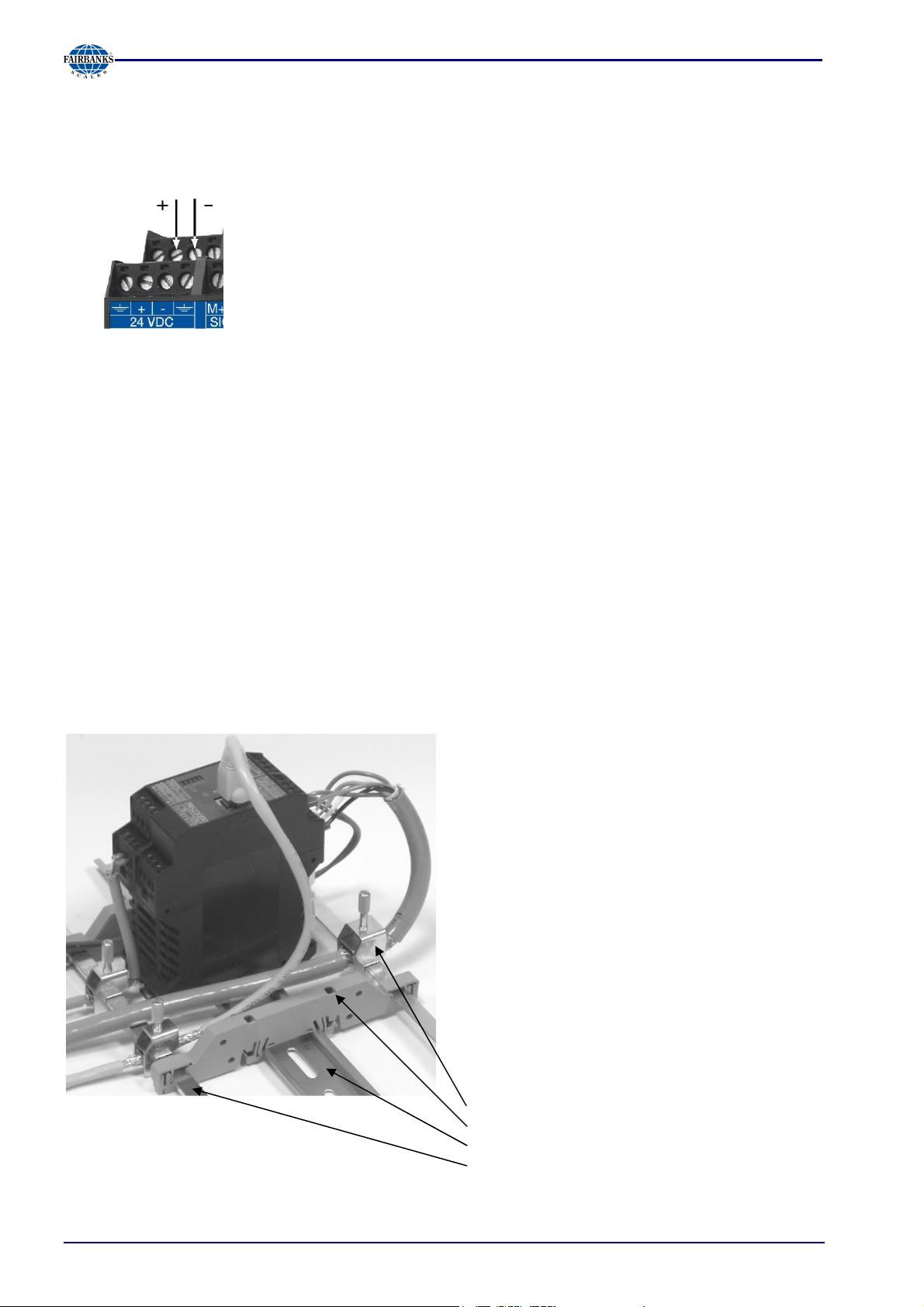
1.3.7 EMC-Compliant Installation
Use only screened data cables
--
Connect screens on both ends with ground
--
Keep unscreened cable ends short
Connect screen rail to cabinet / housing with
-
low impedance
-
Use metal or metalized connector housings
Establish equi-potential bonding between
instruments / system modules (Mandatory for
-
Ex-applications)
-
Use standard reference potential
-
Connect mounting rail to protective earth
Install measure and data cables separately
from power cables
Screen clamp (z.B. Phoenix SK8-D)
Rail connection (z.B. Phoenix AB-SK 65D)
Mounting rail (34mm)
Screen rail (e.g. Phoenix NLS-CU 3/10)
05/11 10 51209 Revision 2
Section 2: PR 5220 Ethernet Transmitter Series
2 PR 5220 Ethernet Transmitter Series
2.1 The Transmitter Versions
Three PR 5220 series transmitter versions are available; subsequent extension of the version is not
possible.
The version is determined unambiguously by the type number. The front foils are adapted to the
version.
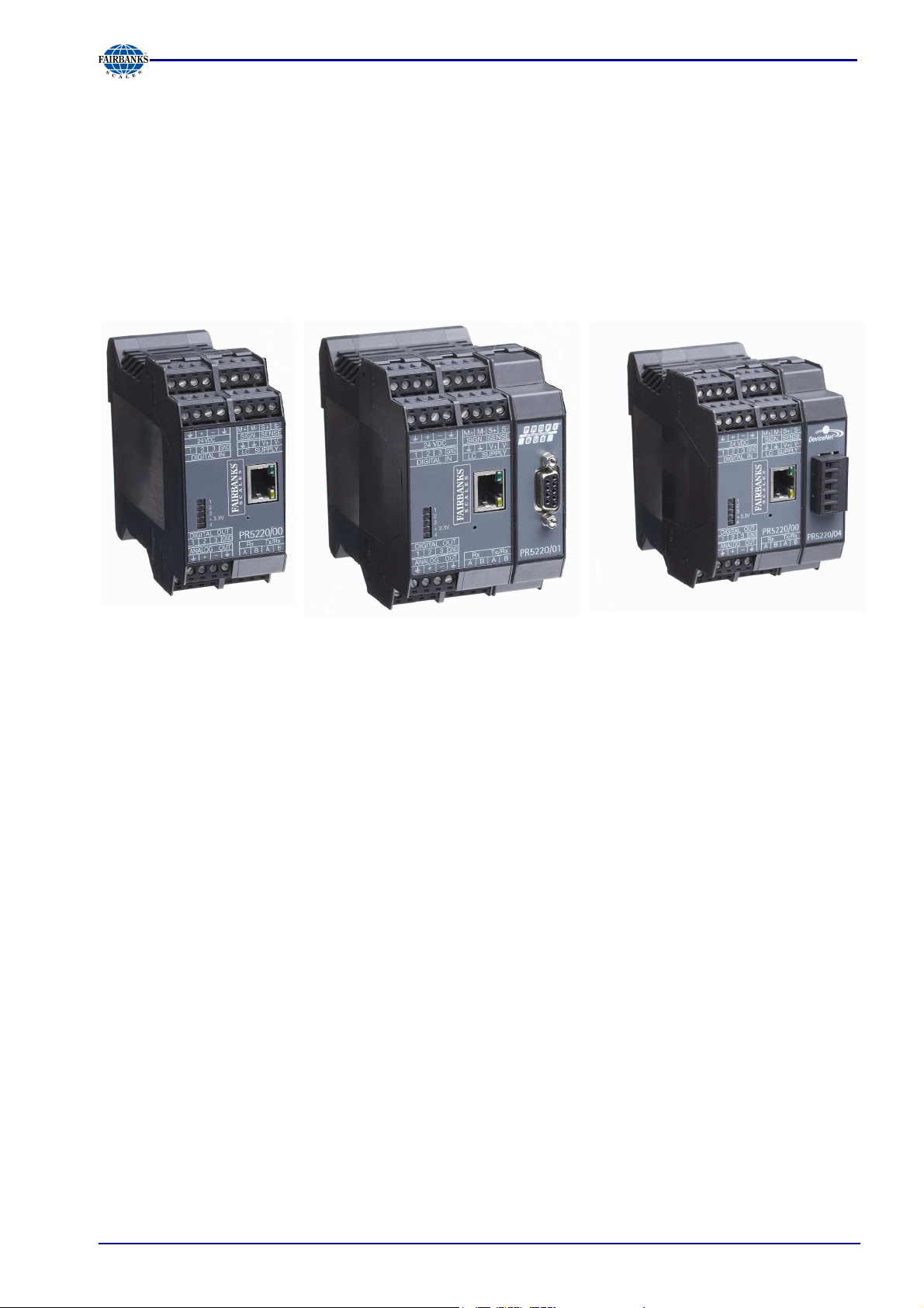
PR 5220/00
PR 5220/01
PR 5220/04
2.1.1 PR 5220/00 Version
This version has digital inputs and outputs as well as an analog output and a LAN adaptor for
configuration and operation of the instrument. Connecting e.g. a remote indicator is possible via the
serial output.
2.1.2 PR 5220/01 Profibus
In addition to PR 5220/00, the instrument is provided with a Profibus port.
2.1.3 PR 5220/04 DeviceNet
In addition to PR 5220/00, the instrument is provided with a DeviceNet port.
05/11 11 51209 Revision 2
Section 2: PR 5220 Ethernet Transmitter Series
2.2 Overview of the Instrument
-
EC test certificate / type approval applied for
-
Accuracy 10,000 e @ 6 samples/sec
-
Internal resolution: 7.5 million counts
-
Linearity: < 0.002%
-
Sampling rate: 6 ... 100/sec selectable
-
Digital filter with selectable characteristic
-
Electrically isolated interfaces
-
3 programmable pairs of limit values
-
24 VDC supply voltage connection
-
Connection using plug-in terminal blocks
-
Socket for LAN adaptor
-
Port for Profibus (/01)
-
The instrument is provided for snap-on mounting on a
standard rail.
-
5 status LEDs für supply voltage, communication, error
detection
Calibration and configuration of the instrument are menu guided
using a PC, or by Profibus commands (PR 5220/01 only).
-
Calibration with weight, using the mV/V method or with load
cell data (“smart calibration”)
-
0/4 ... 20 mA analog output, configurable for gross/net
weight
-
Analog value via Profibus (PR 5220/01 only)
-
3 digital input channels, electrically isolated
-
3 digital output channels, electrically isolated
Communication protocols:
-
RS-422 for remote display
-
RS-485 for SMA protocol
-
Profibus-DP (PR 5220/01 only)
-
DeviceNet (PR 5220/04 only)
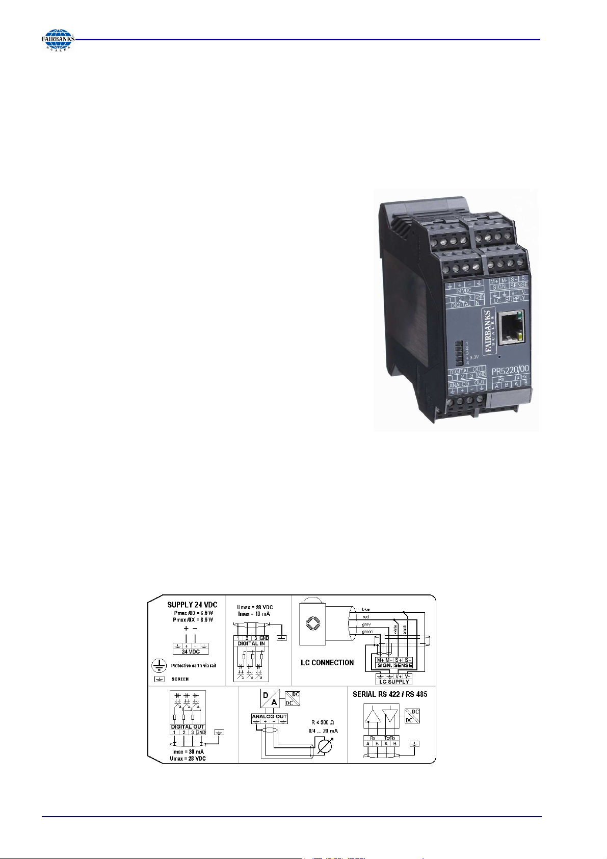
2.3 Label on the Housing
A label with the wiring diagram is located on one side of the instrument:
05/11 12 51209 Revision 2
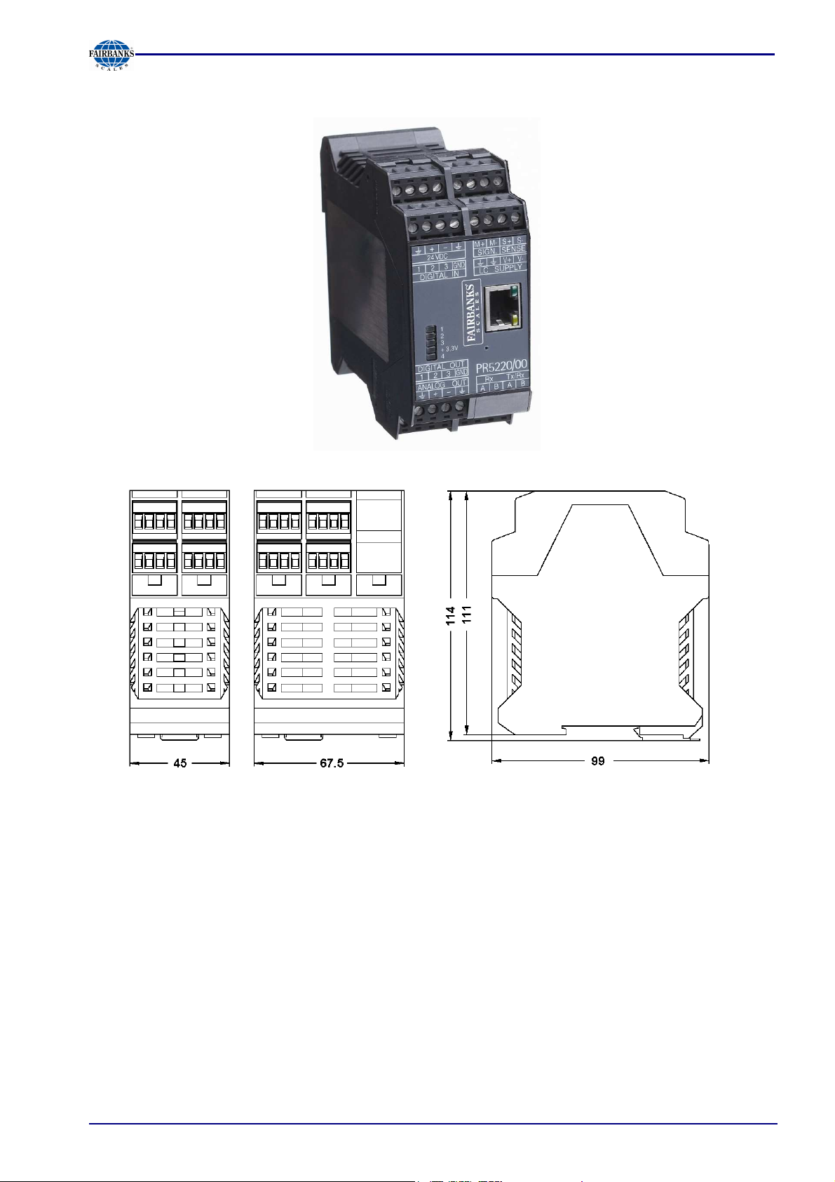
2.4 Housing Dimensions
Section 2: PR 5220 Ethernet Transmitter Series
PR 5220/00 PR 5220/01, -/04
05/11 13 51209 Revision 2
2.5 Operation Using the VNC program
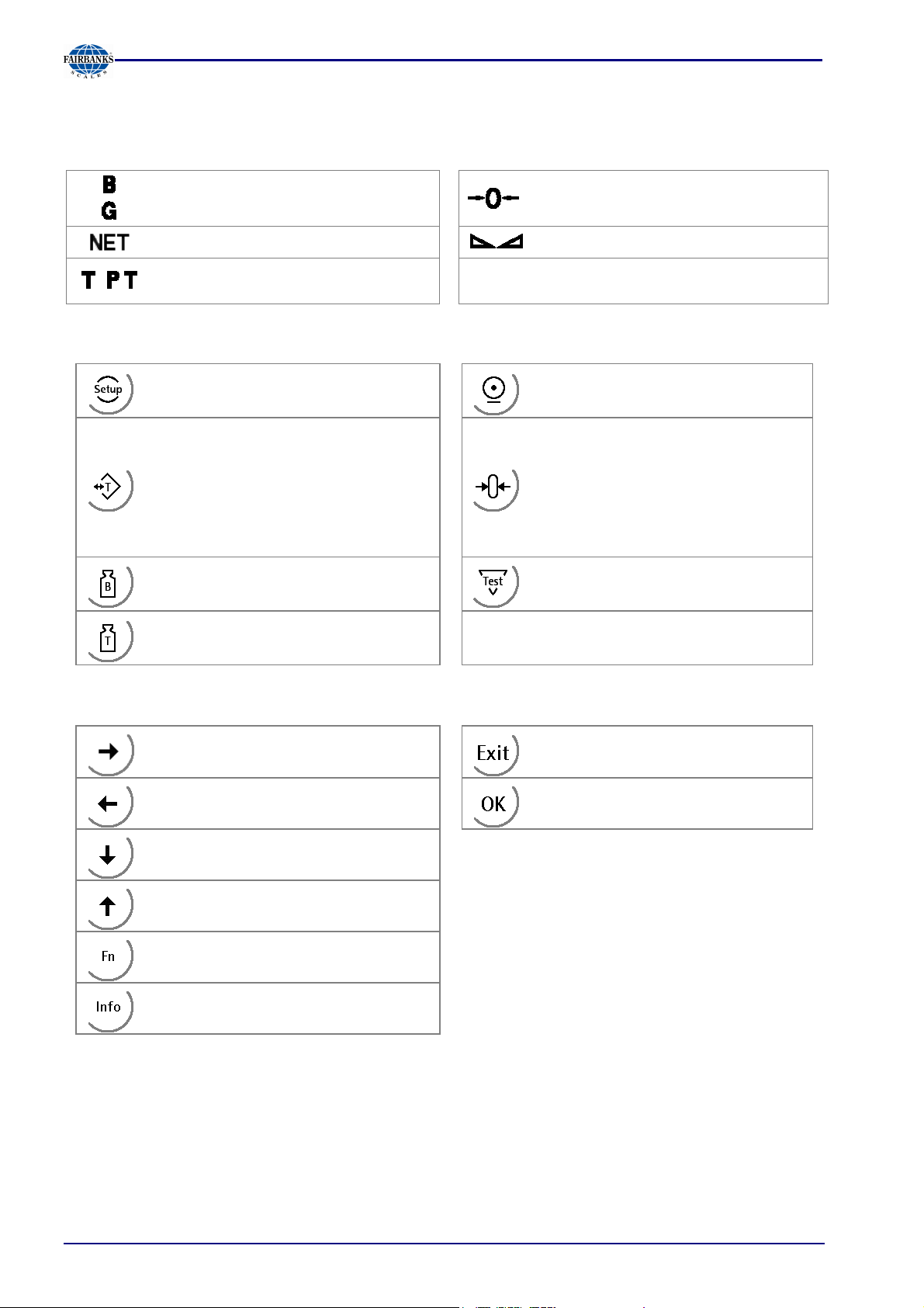
2.5.1 Status Symbols
Section 2: PR 5220 Ethernet Transmitter Series
Gross weight display
(G with NTEP or NSC mode)
Net weight display Stability of the weight value
,
2.5.2 Transmitter Keys
Tare weight or fixtare display
Instrument settings, set-up
Taring, the current gross weight is
stored in the tare memory, provided
that:
- weight value is stable
- indicator not in error status
(function dependent on
configuration)
Gross weight
Tare weight
The weight value is within +/- ¼ d of
zero
Start printing (without function)
Set gross weight to zero, provided
that:
- weight value is stable
- weight within zero setting range
Analog test, weighing function
2.5.3 Navigation Keys, Other Keys
Move cursor right when editing;
selection
Move cursor left when editing;
selection
Scroll down in the menu
Scroll up in the menu
Function key
Information key
Exit from current menu
Enter / confirm
05/11 14 51209 Revision 2
Section 2: PR 5220 Ethernet Transmitter Series
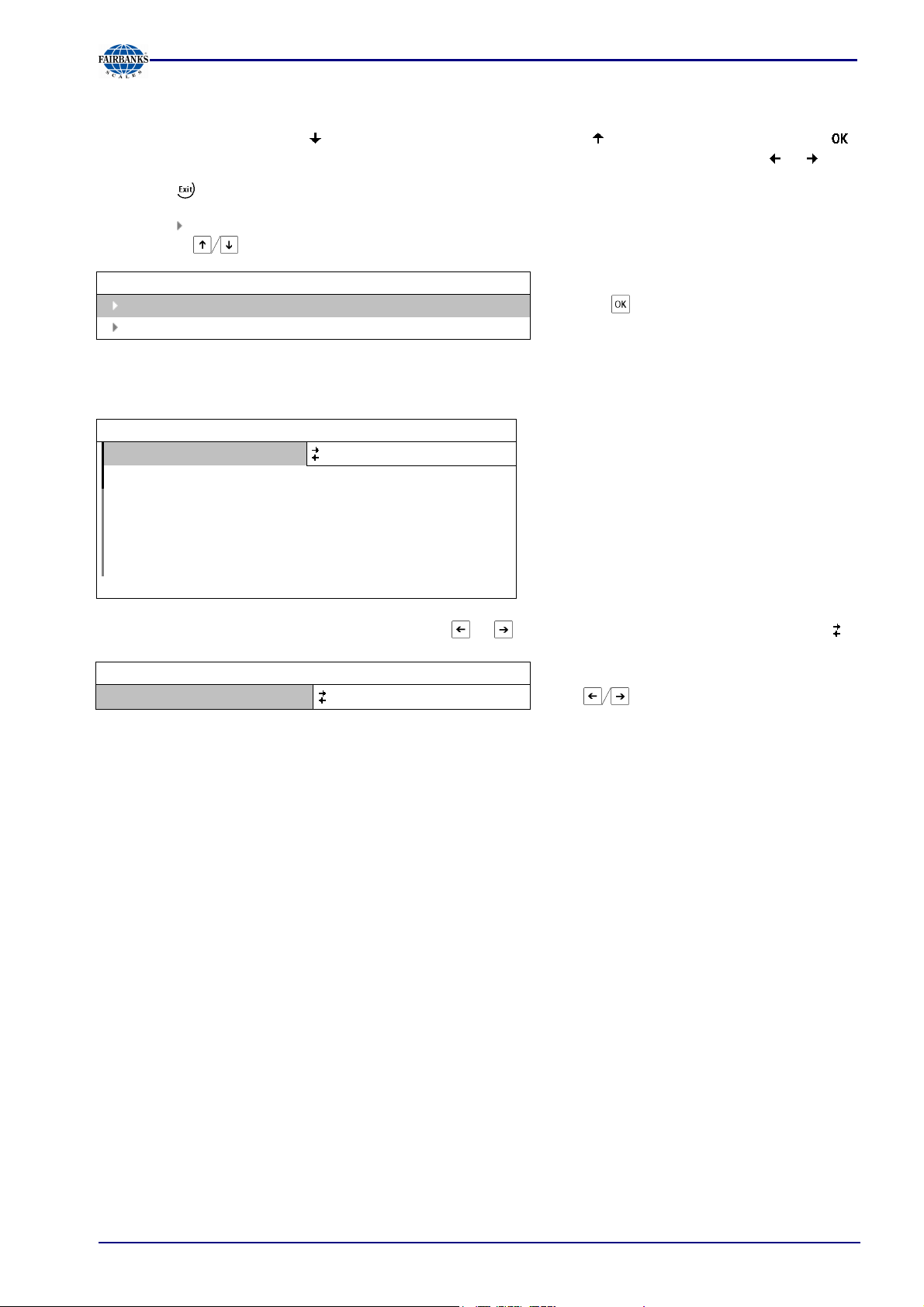
2.5.4 Selection Using the Navigation Keys
Press the down arrow key to scroll down, or the up arrow key to scroll up in a menu. Press
to select a menu item. To choose the desired setting for the selected menu item, press or .
Press the key to exit a menu and continue the operation on the next higher level.
An arrow in front of a menu item indicates that there are menu sublevels. The menu item selected
by pressing is shown inversely.
Info
Show version
Show status
Press the key to select an item.
If the list of menu items is long, a vertical bar graph on the left (black and gray) shows which part of
the list is displayed.
WP A/Calibration
Measuretime
320 ms
Digital filter off
Test mode absolute
W & M
none
Standstill time 0.50 s
Standstill range 1.00 d
Availability of settings options (selectable with or ) is indicated by preceding double arrows .
Measuretime
WP A/Calibration
640 ms Press to select the measuring time.
05/11 15 51209 Revision 2
2.5.5 System Messages during Input
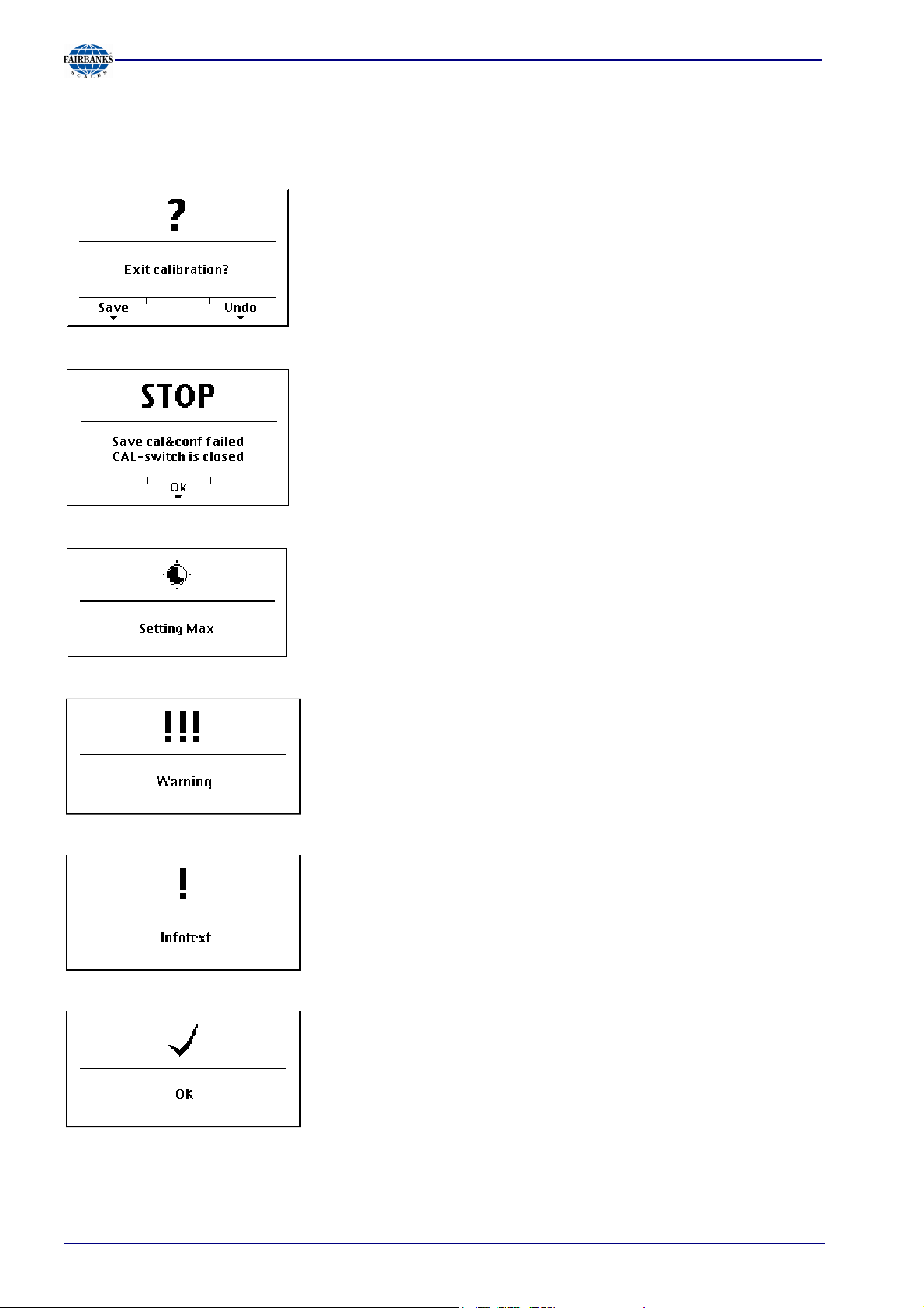
The following types of messages are displayed as confirmation prompts / warnings during input:
Question mark
A question mark indicates that a choice of options (e.g. [Save] for
saving or [Undo] for cancelling) is available.
Stop message
An important indication that an action cannot be executed (e.g., if
saving is not possible because the CAL switch is closed). Read
the description and press [OK] to continue:
Section 2: PR 5220 Ethernet Transmitter Series
Processing
Warning
Informational text
If an action takes a long time (e.g., Max for setting the full scale
deflection), a clock symbol is shown.
A warning is marked by three exclamation points.
An informational text is marked by one exclamation point.
Execution message
Successful execution of an action is indicated by a checkmark.
The graphics are not always included when system messages are depicted in this manual.
05/11 16 51209 Revision 2
Section 3: Installing the Instrument
3 Installing the Instrument
• Before starting work, please read Chapter 1 and follow all instructions.
Further procedures:
• Check the consignment: unpack the components specific to the application.
• Safety check: inspect all components for damage.
• Make sure the on-site installation is correct and complete including cables, e.g. power cable fuse
protection, load cells, cable junction box, data cable, console/cabinet, etc.
• Follow the instructions for installation of the unit relating to application, safety, ventilation, sealing
and environmental influences.
• Connect the cable from cable junction box or platform/load cell.
• If applicable: connect other data cables, network cables, etc.
• Connect the instrument to the supply voltage.
• Check the installation.
05/11 17 51209 Revision 2
Section 3: Installing the Instrument
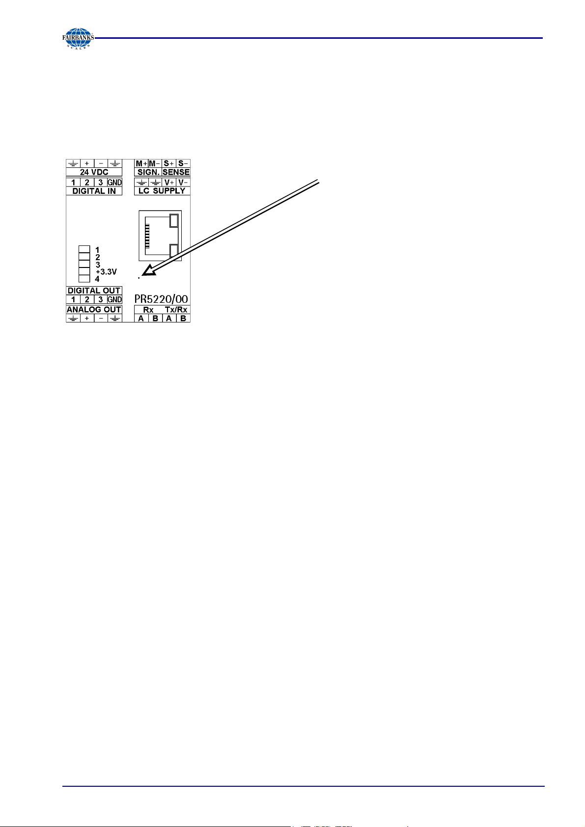
3.1 Network Port
The network port is built in as standard equipment. The LEDs on the connector indicate whether the
port is functioning.
Remote operation of the instrument from the PC is
possible; install VNC program version 3.3.7 on the PC.
For setting the network address, see Chapter 5.2.2.
Transfer rate: 10 Mbit/sec, 100Mbit/sec,
full/half duplex, auto-detection
Connection
method:
Cable: CAT 5 patch cable, shielded twisted pair
Cable impedance: 150 ohms
Connection: RJ45 socket on top of housing
Point to point
05/11 18 51209 Revision 2
Section 3: Installing the Instrument
3.2 Connections
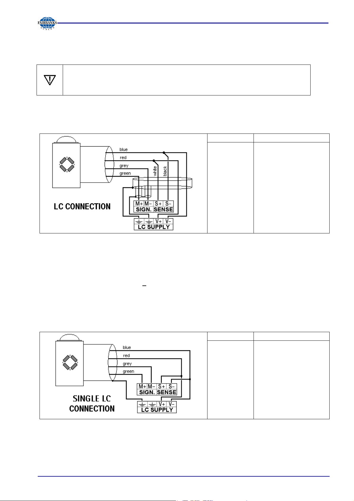
3.2.1 Load Cell Connection
The cable colors shown in this chapter are applicable to the PR 62XX series load
cells.
Before connecting other types, please, carefully follow the information related to the
assignment of load cell / platform cable colors.
3.2.2 Connection Using 6-Wire Technology
See also label on the housing outside (Chapter 2.3) and manual of the cable junction box.
Terminal
SIGN. M+
SIGN. M-
SENSE S+
SENSE S-
LC SUPPLY
V+
LC SUPPLY
V-
Description
+ signal / LC output
- signal / LC output
+ sense
- sense
+ supply / excitation
- supply / excitation
Recommendations: - Install cable in steel pipe connected to earth potential
- Min. distance to high-voltage cables: 1m
Load cell supply circuit:
The load cell supply voltage is fixed to 12VDC and protected against short circuit
Load resistance of load cells > 75 ohms, e.g. 8 load cells of 650 ohms each
3.2.3 Connection of a Load Cell in 4-Wire Technology
Note that links between SENSE S+ and LC SUPPLY V+ and between SENSE S- and LC SUPPLY
V- directly at the transmitter must be provided.
Terminal
Description
SIGN. M+
SIGN. M-
SENSE S+
SENSE S-
LC SUPPLY
V+
LC SUPPLY
+ signal / LC output
- signal / LC output
+ sense
- sense
+ supply / excitation
- supply / excitation
V-
05/11 19 51209 Revision 2
Section 3: Installing the Instrument
3.2.4 Connecting PR 6221 Load Cells
See PR 6021/08, -/68 operating manual.
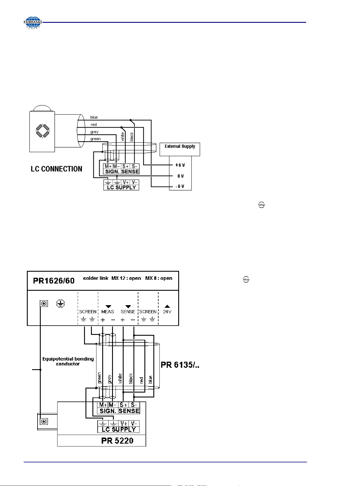
3.2.5 External Load Cell Supply
The internal load cell supply voltage of PR5220 (V+, V-) is not connected.
The common line of the symmetrical external supply must be connected to the same terminal of PR
5220 as the shield of the load cell / extension cable.
Specification of external supply: +/- 6 VDC + 5%, -30%; max ripple. 50 mVpp; max. asymmetry +/3%. An external supply voltage smaller than 8 VDC (+/- 4 VDC) must be set under -[Calibration]-
[Param]-[External supply].
3.2.6 Connection via PR 1626/60
Connect the instrument to PR 1626/60 as described below. For additional connections, refer to the
PR 1626/60 manual. The internal load cell supply voltage of PR5220 (V+, V-) is not connected.
If MX8 is closed, [below 8VDC] must
be set under -[Calibration]-[Param]-
[External supply].
05/11 20 51209 Revision 2
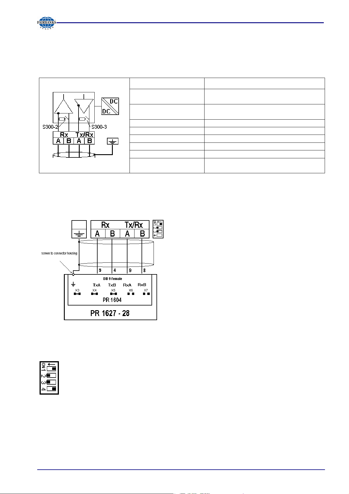
3.2.7 RS-422/485 Interface
The interface is intended for connecting a PR 1627 type remote display, a PR 1628 terminal or a
PC for data transmission using the SMA protocol.
Connection method: 4-pin plug-in terminal block
Section 3: Installing the Instrument
Number of channels /
type:
Transfer rate (Bits/s): 300, 600, 1200, 2400, 4800, <9600>,
Bits / stop bits: <8 / 1> or 7 / 1
Parity: <even>, <none>
Signals: RxA (R-), RxB (R+), TxA, TxB
Electrical isolation: Yes
Cable length: Max. 1000m
Cable type: Shielded twisted pair (e.g. LifYCY
<...> = default settings (factory settings)
Connection of a PR 1627 remote display or of a PR 1628/00, -/60 or -/24 terminal
(over the PR 1604 interface)
1 RS-422 / RS-485 , full / half duplex
19200
2x2x0.20)
The following operations are possible from the
connected terminal / display:
Test
Set tare
Reset tare
Set zero
S300
ON <----- OFF ----->
2-wire connection (d) 4-wire connection
(d) Receiver terminating resistor 'ON' Receiver terminating resistor 'OFF'
(d) Transmitter (rec.) terminating resistor
'ON'
Calibration data and parameters
secured
(d) - default = factory setting
05/11 21 51209 Revision 2
Transmitter (rec.) terminating resistor 'OFF'
(d) Calibration data and parameters not
secured

3.2.8 Analog Output
Section 3: Installing the Instrument
Connection method: 4-pin plug-in terminal block
Number of outputs: 1 current output, output
voltage via external resistor
Output: Gross, net weight or via
Profibus
Range: 0/4 ... 20mA, configurable
Resolution: E.g. 0 - 20 mA in max.
40,000 counts
Linearity error: @ 0 - 20mA: <0,05 %
@ 4 - 20 mA: <0,025 %
Temperature effect: < 100 ppm/K
Load: 0 ... max. 500 ohms
Protected against short
Yes
circuit:
Electrical isolation: Yes
Cable length (shielded): 150 m (current output)
0/4 ... 20mA
Analog signal,
current output.
The current is supplied
directly via the terminals.
0 ... 10V
Analog signal,
voltage output
The voltage level
corresponds to the voltage
drop across the 500-ohm(10 ppm/K) resistor.
05/11 22 51209 Revision 2
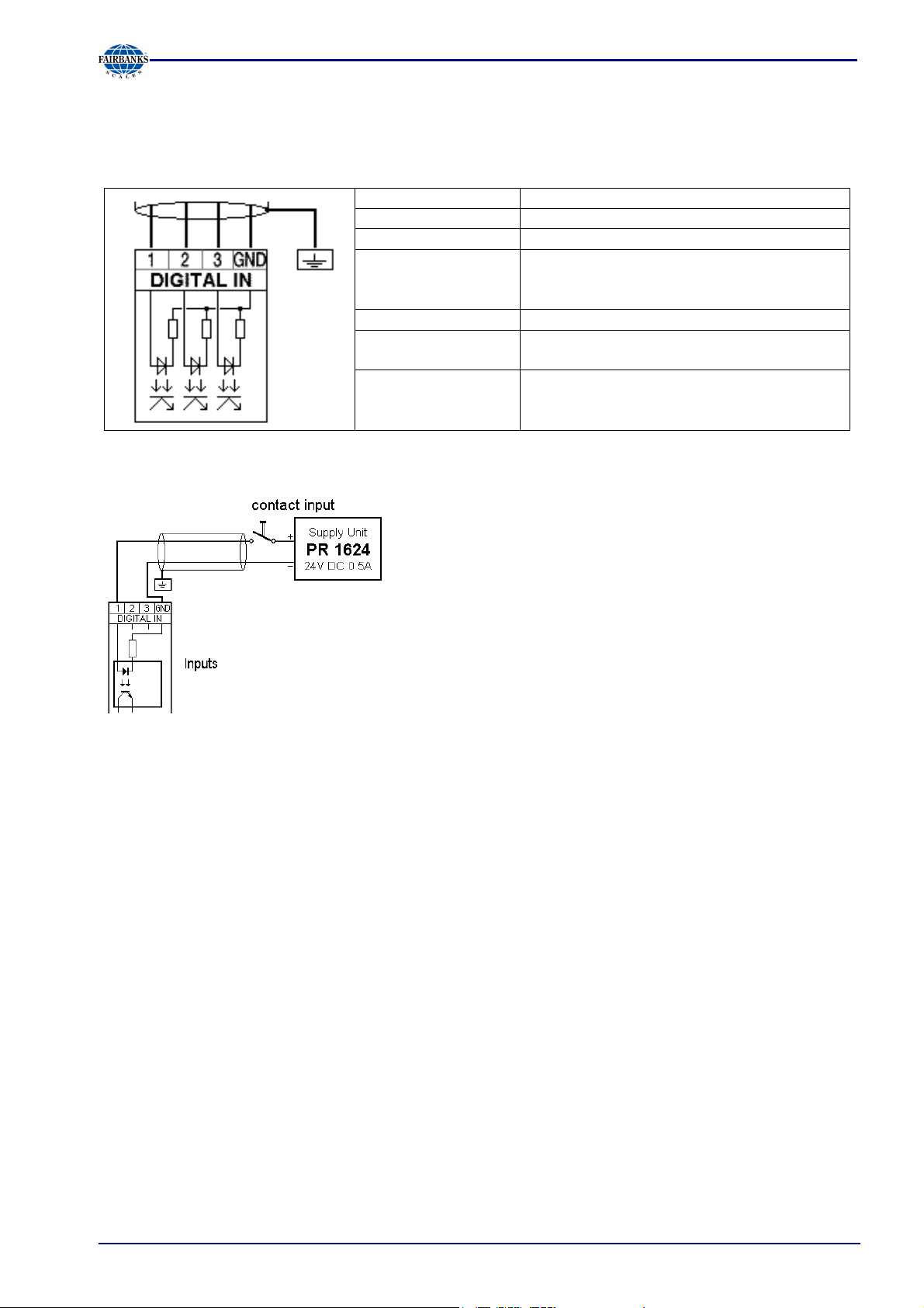
3.2.9 3 Optocoupler Inputs
The optocoupler inputs have one common potential (GND) for the input group that is separated
from the common potential of the output group.
Connection method: 4-pin plug-in terminal block
Cable: Shielded, max. 50 m
Number of outputs: 3
Input signal: External supply required
10 ... 28 V DC for 'high' level
0 ... 5 V DC for 'low' level
Input voltage: Max. 28 V DC
Input current: < 11 mA @ 24 V DC
< 5 mA @ 12 V DC
Electrical isolation: Yes; a common minus potential for the
group of 3 inputs
Example: contact input connection
Section 3: Installing the Instrument
When a voltage >= 10 VDC is applied to the terminals (in
the example :1-GND), input 1 is active (true).
05/11 23 51209 Revision 2
Section 3: Installing the Instrument
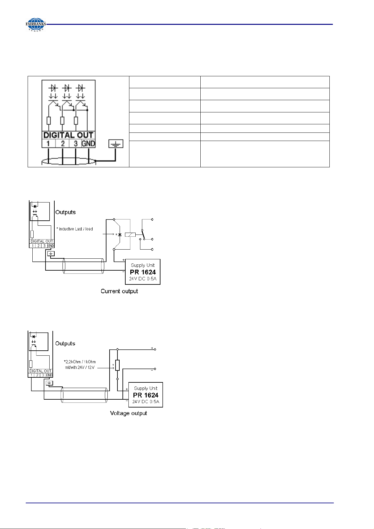
3.2.10 3 Optocoupler Outputs
The optocoupler outputs have one common potential (GND) for the output group that is separated
from the common potential of the input group.
Connection method: 4-pin plug-in terminal block
Cable: Shielded, max. 50 m
Example: relay control connection
Number of outputs:
Output signal:
3
External supply required
Output current: Max. 30 mA
Output voltage: Max. switching voltage: 28 VDC
Electrical isolation:
Yes; a common minus potential for the
group of 3 outputs
When output 1 is active (true), the relay switches.
For protection of the output circuit, relays with freewheel diode must be provided.
Example: voltage output connection
When output 1 is active (true), the output voltage
changes from 24 /12 VDC into < 3 VDC. A load
resistance of 2.2 /1 kohms must be provided.
05/11 24 51209 Revision 2
Section 3: Installing the Instrument
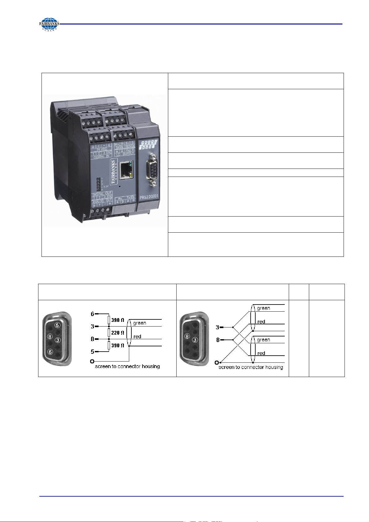
3.2.11 Profibus Interface (PR 5220/01 only)
Communication protocols and syntax comply with the Profibus-DP standard to IEC 61158 with
transfer rates up to 12 Mbit/s.
Transfer rate: 9.6 kbit/s to 12 Mbit/s,
baud rate auto-detection
Protocol: PROFIBUS-DP-V0 slave
to EN 50 170 (DIN 19245),
mono or multi-master systems are
supported. Master and slave
devices, max. 126 nodes possible.
Watchdog timer
Transport: EIA RS-485 , Profibus DIN 19245
Part 1
Cable: Profibus special colour: violet
Shielded twisted pair cable
Cable impedance: 150 ohms
Certificates: Profibus test center Comdec in
Germany and PNO (Profibus User
Organization).
Suitable for industrial applications to
CE, UL and cUL
Electrical isolation: Optocoupler in lines A and B (RS-
485)
Cable length: Max. distances 200m can be
extended with 1.5 Mbit/s by means
of additional repeater
Connection to the Profibus is using the 9-contact plug-in socket on the front panel.
The transmitter is the only or last slave on
the bus
The transmitter is not the only or
last slave on the bus
PIN Signal
RxD/TxD3
4
5
6
8
P
CNTR-P
DGND
VP
RxD/TxD-
P
05/11 25 51209 Revision 2
Section 3: Installing the Instrument
3.2.12 DeviceNet Interface (PR 5220/04 only)
It is a complete DeviceNet adapter (SLAVE) with CAN controller and transfer rates of up to 500
kbit/s.
Connection: 5-contact screw terminal block (plug-
in)
Transfer rate: 125, 250 and 500 kbit/s
Topology: Parallel bus
Protocol: DeviceNet master/slave
Polling method (polled I/O)
CRC error detection
to IEC 62026 (EN50325)
Max. 64 station nodes
Max. data width 512 bytes input &
output
Transport: EIA RS-485
Configuration: EDS file
MAC-ID (1…62)
Certificates/
conformity:
Compatible with DeviceNet
specification
Vol 1: 2.0, Vol 2: 2.0
ODVA certificate in accordance with
conformity test software version A-12
Suitable for industrial applications to
CE, UL and cUL
Cable: DeviceNet, color: petrol-green
2x2 shielded twisted pair
Cable impedance: 150 ohms
Bus termination: 120 ohms at the cable ends
Electrical isolation: Yes, optocoupler and DC/DC
converter
Connecting diagram for a master with three slaves
05/11 26 51209 Revision 2
Section 4: Controls
4 Controls
4.1 Status Indicator LEDs
The instrument has 5 green LEDs for indication of the operating or error status.
Power supply, bus connection
* The LED for the bus activity (PR 5220/01 a. PR 5220/04) is lit as soon as there is a connection. It
continues being lit, also when there is no communication, or when the physical connection is cut.
Weight status indicator LED
4.1.1 Weight error status:
Power on Bus Bus connection
not provided
lit
lit blinks 1 Hz
Standstill Center zero Below zero or
above max.
capacity
lit
lit
lit
Error 1
Arithmetic
blinks 1 Hz blinks 1 Hz Alternate bl.
blinks 1 Hz blinks 1 Hz Alternate bl.
blinks 1 Hz blinks 1 Hz blinks 1 Hz blinks 1 Hz Alternate bl.
Error 7
(negative)
Error 2
Overload
Error 3
(> 36 mV)
Error 6
Sense monit.
1Hz
1Hz
1Hz
05/11 27 51209 Revision 2
Section 5: Commissioning
5 Commissioning
The meaning of indicator LEDs and the operating concept are described in Chapter 4.
5.1 Data Backup/Power Failure
The calibration data and parameters as well as all configuration and interface data are stored in a
non-volatile (EAROM) memory. Unauthorized data changing can be prevented by an access code.
Additional write protection is provided for calibration data and parameters (CAL switch, see
Chapter 5.1.1).
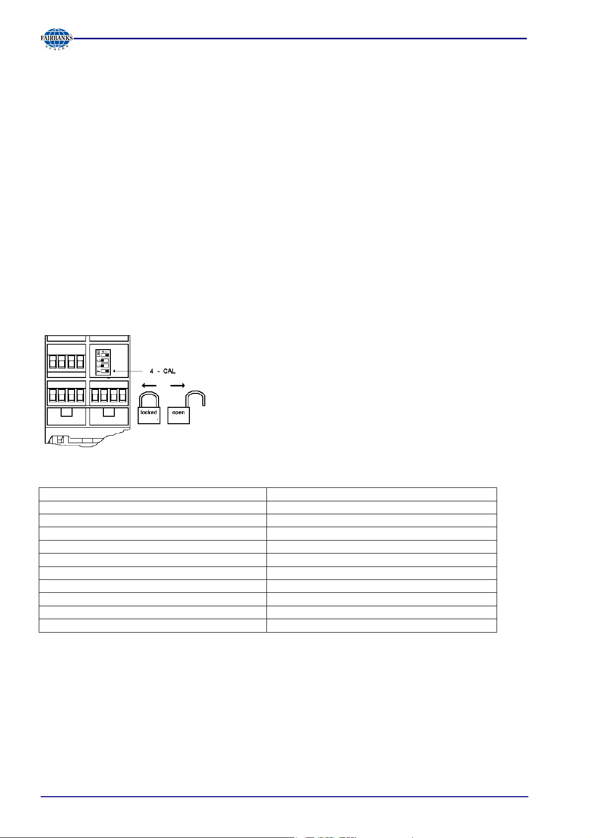
5.1.1 CAL Switch
The CAL switch protects the calibration data / parameters against unauthorized access.
When the CAL switch is in 'open' position, the calibration data and parameters can be changed
using the PC program or via the Profibus connection.
With the CAL switch in the 'closed' position, the calibration data (e.g. dead load, Span) and
Parameters (e.g. measure time, zero tracking etc.) cannot be changed.
The CAL switch is located under a cover that can be opened by
means of a knife.
For ’legal-for-trade’ applications, set the CAL switch (4) to the
left position and seal the cover.
5.1.2 Factory Settings
Calibration data <default> Calibration data <default>
Full scale (Max) <3000> <Kg> Measure time (M) <320>ms
Scale interval <1> Measuring rate <160>ms
Dead load <0.000000>mV/V Standstill time <1>M
Span <1.000000>mV/V Standstill range <1.00>d
Tare timeout <8>M
Calibration parameters <default> <Absolute> test mode
Overload (range above Max) <9>d Zero-setting range <50.00>d
* W & M mode <off> Zero-tracking range <0.25>d
Filter <off> Zero-tracking step <0.25>d
Frequency <1.56 Hz> Zerotrack repeat <0>M
* Parameter W&M must be set to 'on' or 'off' prior to input of the calibration data, see Chapter
5.4.20.
.
05/11 28 51209 Revision 2
Section 5: Commissioning
5.2 Switching on the Instrument
The instrument can be put into operation and calibrated using a PC with the VNC program (on the
CD packed with the instrument), an Internet Browser or the ConfigureIt program.
5.2.1 Resetting the Instrument, Activating 'DHCP'
The instrument can be reset using a pin with a diameter of 1.0 mm
(e.g. paper clip).
By actuating during approx. 1 second, the program is re-started.
When actuating during approx. 3 seonds, 'DHCP' is activated in the
instrument (independent of the previous settings). This ensures that a
valid address for identification of the instrument in the network can be
assigned to the instrument by a server.
05/11 29 51209 Revision 2
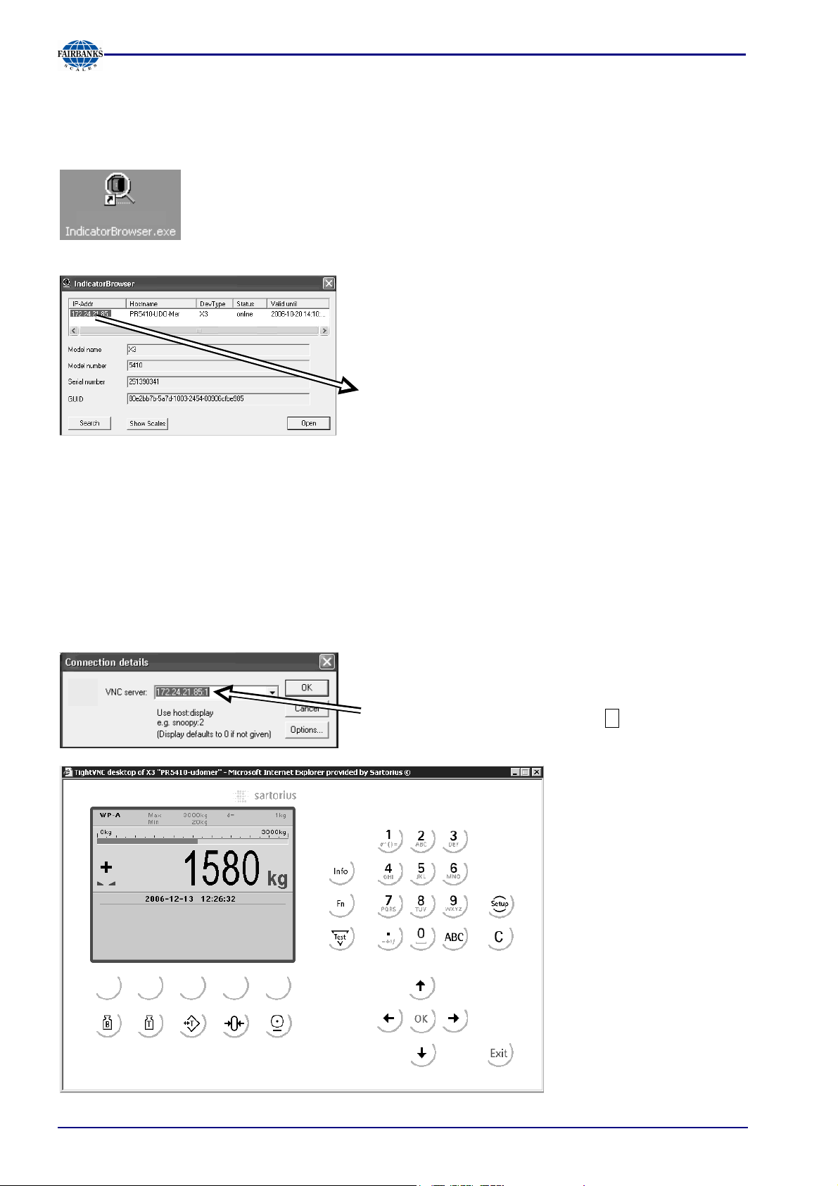
5.2.2 Searching the Instrument in the Network Using 'IndicatorBrowser'
The address can be determined using the 'IndicatorBrowser' (in a directory on the CD-ROM packed
with the instrument) program.
Install and start the 'IndicatorBrowser'.
When the instrument is connected to a network, it is
“default” in the DHCP mode, i.e. an address is
assigned to it by the server. This address, e.g.
172.24.21.85, can be determined using the
‘IndicatorBrowser’ program.
Section 5: Commissioning
5.3 Operation Using a PC
5.3.1 Operation Using the VNC Program
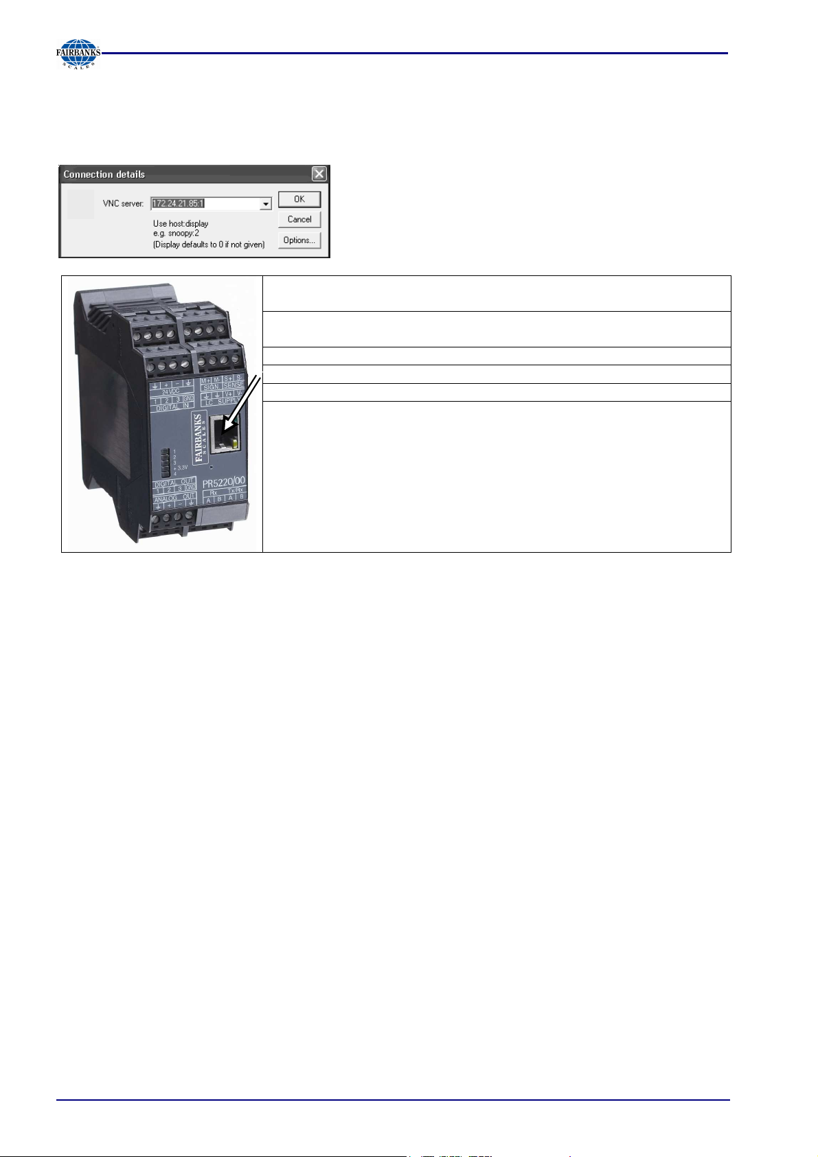
VNC stands for 'virtual network computing' and is a program for remote operation of computers.
The program distinguishes between the VNC server and VNC client (viewer). The server program is
part of the instrument software. The client program (viewer) must be installed and executed on the
PC to be used for operating the instrument.
For direct operation using the VNC program, the IP
address (extended by :1) must be specified when you
run the program, e.g. 172.24.21.85:1.
The address range of the
controlling PC can be
limited in the instrument;
see Chapter 5.6.5.
The operator interface of
the VNC program appears:
05/11 30 51209 Revision 2
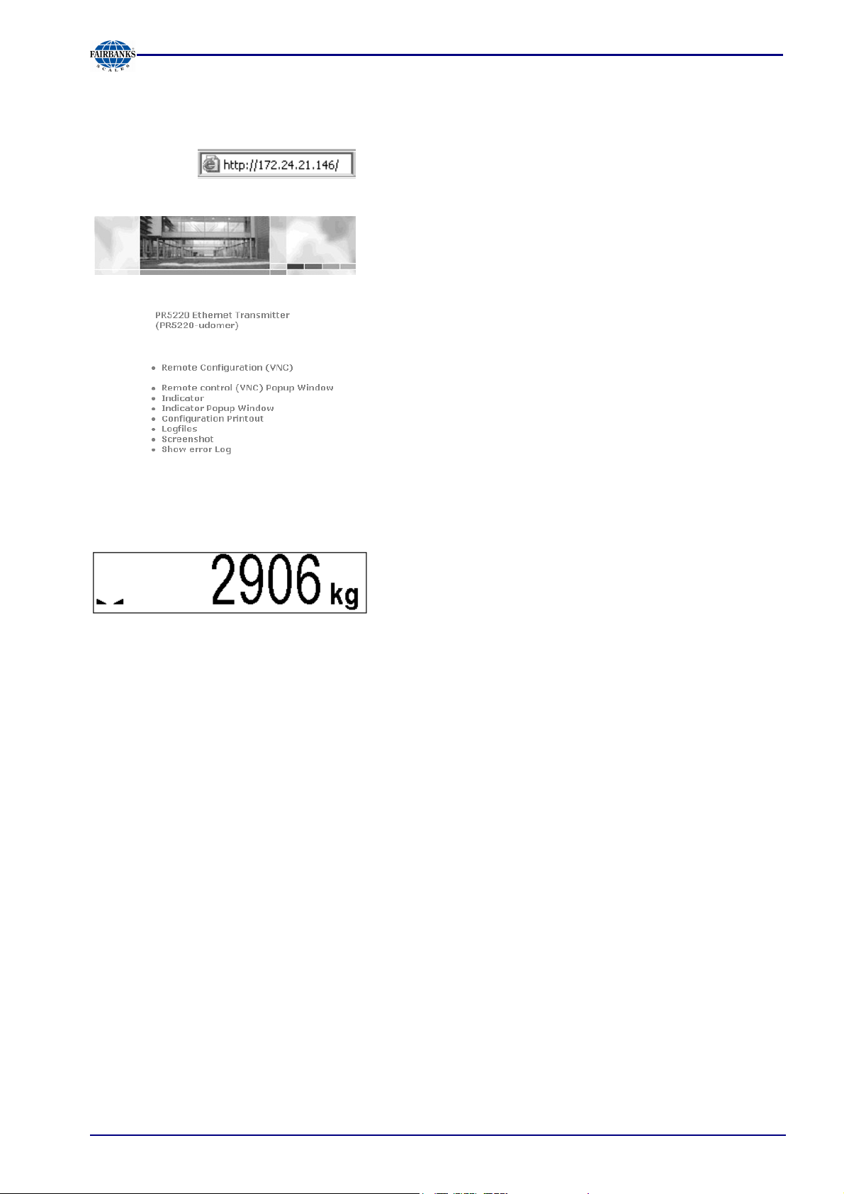
5.3.2 Operation Using Internet Browser
With the Internet browser, the IP address must be filled in.
Example:
Section 5: Commissioning
For instrument operation using the VNC program without additional installation of VNC, see Chapter
5.3.1 .
The weight value is displayed with the unit and status
symbols.
[Configuration Printout]
Can be used for printing the configuration data as a text file.
[Logfiles]
[Screenshot]
Device display for saving the display
[Show error Log]
Display of the error messages
05/11 31 51209 Revision 2

Section 5: Commissioning
5.3.3 INFO Function
When you press , the program releases and status messages are displayed. The key also has
other functions; see Chapters 5.4.3 and 5.4.15.
Show version
Show status
Show HW-slots
Info
For operation, see application manual.
When you select [Show version], the installed program releases and the board number are
displayed:
Info/Version
Firmware Rel. 01.00.00
2006-12-02 10:50
Appl-DEFAULT Rel. 01.00.00
2006-12-02 10:50
Bios Rel. 01.00.00
2006-12-02 10:50
Boardnumber 251398426
(different from the device serial number)
Firmware release and creation date
Application release and creation date
BIOS release and creation date
Main board identification number
When you select [Show status], instrument status information is displayed:
Info/Status
Free system RAM 6328 of 15212 kb
CAL-Switch closed
(opened if CAL switch is open)
When you select [Show HW-slots], the installed plug-in cards are displayed:
Info/HW-Slots
Builtin RS 232
Slot 1
PR 5510/0
4
RS 485/232
Slot 2 -empty-
Slot 3 Builtin Digital I/O
Slot 4 Profibus-DP
Standard serial interface
Standard interface, digital I/Os
05/11 32 51209 Revision 2

Section 5: Commissioning
5.3.4 Setup Function (VNC)
Press to configure the main operating parameters. The instrument configuration depends on the
application and the plug-in cards installed.
Calibration is in a simple dialogue. Compliance with the relevant (verification) standards must be
checked by the person commissioning the instrument or the verification officer. To protect the
calibration data from overwriting, close the CAL switch on the back panel of the instrument. On
legal-for trade instruments, the CAL switch must be sealed in the closed (write-protected) position;
see Chapter 5.1.1.
5.3.5 Setup Menu
- Serial ports parameter
- Remote display
- SMA
- Param
- Operating parameter
- AccessCode
- SetTareKey
- SetZeroKey
- Fieldbus parameter
- Network parameter
- Calibration
-Limit parameter
- Limit 1/2/3 on/off
-Digital I/O parameter
- Output 1/2/3
- Limit 1/2/3 on/off
- Analog output parameter
Limit 1/2/3 'on'/ 'off', Action, Condition; see Chapter 5.7.5
Configuring outputs; see Chapter
Inputs, Action, Condition; see Chapter 5.7.4
<none>, Builtin RS232
not used <none>, Builtin RS232, Slot 1 .. 2 RS485, Slot 1 ... 2 RS
232
Builtin RS232, Assigned to, Protocol, Baud rate., Bits, Parity,
Stop bits,
Access code for changes
Tare&reset tare, tare&tare again, disabled
Only when not tared, reset tare on zeroset , disabled.
Only for PR 5220/01 and /04, see Chapter 5.6.4
Hardware address (read only), Instrument name, IP address,
Subnet mask, Standard gateway, VNC-Client (access restriction)
New, Modify, Param, see Chapter 5.3.6
Gross, Net, Select, Transparent; see Chapter 5.8
05/11 33 51209 Revision 2

Section 5: Commissioning
5.3.6 Calibration Menu
- Calibration
- New
Reset Span and deadload
- Max 0.00001 ...<3000>... 999999 <kg>, t, lb, g
- Scale interval <1>, 2, 5, 10, 20, 50
- Deadload at <0.000000 mV/V> or [by load]
- Max at <1.000000 mV/V> or [by load]
by load 0.00001 ... 999999 <kg>, t, lb, g
- Calibrated at (Display only)
- Sensitivity (µV/d) (Display only)
- Test Determine test value
Exit calibration Save or cancel changes
- Modify
see New
- Param
- Measuretime 5 ms, 10, 20, 40, 80, 160, <320>, 640, 960, 1280, 1600ms
- Digital filter <off>, Bessel, aperiod., butterw., tscheby.
- External supply <8 -12 VDC>, below 8 VDC
- * Fcut Cut-off frequency, only unless filter 'off', 0.1 - 80.0 Hz
- Test mode <Absolute>, relative
- W & M <none>, OIML, NSC, NTEP
- Standstill time 0.01 s…<0.50 s> ... 2.0 s (range is dependent on
- Standstill range 0.00 d ... <1.00 d> ... 10.00 d
- Tare timeout 0.1 s ... <2.5 s> ... 25 s, timeout due to instability
- Zeroset range 0.00 d ... <1.00 d> ... 10.00 d
- Zeroset range 0.00 d ... <1.00 d> ... 10.00 d
- Zerotrack step 0.00 d ... <1.00 d> ... 10.00 d
- Zerotrack time <0.0 s> ... 25 s
- Overload 0 d ... <9 d> ... 999900 d
- Min 0 d ... <50 d> ... 999900 d, minimum weight
- Range mode <Single range>, multiple range, multi-interval
- * Range limit 1 In weight, unit same as Max, transition from small to
- * Range limit 2 In weight, unit same as Max, transition from medium to
Only for minor modifications/ setting new dead load,
Calibration of weighing electronics
Contin, Cancel
otherwise [New
response time)
medium scale interval, *only for multiple range or multiinterval
high scale interval, *only for multiple range or multi-interval
- View(when - View(when CAL switch closed)
- Max
- Scale interval
- Deadload at
- Max at
- Calibrated at
- Sensitivity (µV/d)
- Param
(Display only)
(Display only)
(Display only)
(Display only)
(Display only)
(Display only)
Items as for Param. (display only)
05/11 34 51209 Revision 2

Section 5: Commissioning
5.4 Calibration
5.4.1 Calibration using weights, mV/V or load cell data can be done using the VNC
program. During calibration, the instrument must be set to gross weight display
(reset tare, if necessary).
For a ’legal-for-trade’ application, set the mode under -[Calibration]-[Param] to [W&M] before
starting calibration; see Chapter 5.4.20. Select [New] to go to the maximum capacity [Max] (see
chapter 5.4.7), select the scale interval and determine the dead load. Now calibrate the maximum
capacity by applying a calibration weight, in mV/V or with load cell data. After determining the test
value, the menu can be closed as described in Chapter 5.4.18, in order to save the new settings.
Calibration data can be protected by the CAL switch (see Chapter 5.1.1), which must be sealed in
the closed (write-protected) position for ‘legal-for-trade’ applications.
5.4.2 Displaying Calibration Data
Cannot calibrate!
CAL_switch is closed
Cannot calibrate!
Scale is tared
With [View], the calibration data can be displayed, but not changed.
WP A/View Calibration
Max 3000 d 3000 kg
Scale interval 3000 d 1
kg
Deadload at 0.00 kg 0.000000
When the CAL switch is closed, the following message is displayed;
only data display possible with [Param]:
If the scale was tared, the following message is displayed, data
display with [View], reset tare with [Res.tar.], return with [Cancel]:
Number of scale intervals and max.
capacity
Scale interval
Dead load in weight and mV/V
Max at 3000.00 kg 1.000000
Calibrated at 3000.00 kg 1.000000
Sensitivity 833.33 4.000000
Param
Weight and mV/V for maximum capacity
Test load* and corresponding mV/V
Number of internal counts and voltage
per scale interval
The calibration data and parameters (press [Param]) are displayed in the format
entered/determined during calibration.
* After input with mV/V, the maximum capacity and the mV/V value entered are displayed.
5.4.3 Increased Resolution (10-Fold)
In the -[Calibration] menu, the weight is displayed with 10-fold resolution (also with the CAL
switch closed) when you press the key , and marked as an invalid weight with above the
weight unit. After 5 s, the display returns to normal resolution, or you can press the key to return
to normal display immediately.
05/11 35 51209 Revision 2

4.000000
3000 d
3000 d
1.07 kg
3000.00 kg
1.000000
3000.00 kg
4.000000
5.4.4 Selecting the Calibration Mode
You can choose between [New] and [Modify] with the softkeys:
New Modify Param
5.4.5 New Calibration
Open the menu via -[Calibration].
When you press [New], the data is set to default first and calibration is started.
SPAN and deadload
will be reset
Default settings with [New]:
WP A/Calibration
Max 3000 d
Scale interval 3000 d
Deadload at
Max at
Not calibrated
Sensitivity
833.33
You are prompted to confirm.
Press [Continue] for the default settings, or [Cancel] to cancel the
selection.
3000 kg
1 kg
0.000000
1.000000
Section 5: Commissioning
Test
5.4.6 Changing the Calibration
[Modify] may be used only for minor changes (e.g. changing the dead load, adapting mV/V
values for dead load and/or Max); otherwise, always use [New].
Open the menu via -[Calibration]-[Modify].
WP A/Calibration
Max
Scale interval
Deadload at
3000 kg
1 kg
0.000358
Max at
Calibrated at
Sensitivity
833.33
1.000000
by load by mV/V
Test
For setting a new value for Dead load, press
to select [Deadload] and either enter a new
value with [by mV/V] or discharge the scale/hopper and press [by load].
Exit calibration
without CalcTest?
When closing the menu with you are prompted whether the menu
should be closed without calculation of the test value:
Reply [Yes] to close the menu.
05/11 36 51209 Revision 2

Section 5: Commissioning
5.4.7 Determining the Maximum Capacity (Max)
The maximum capacity (Max) determines the maximum weight without dead load of the weight to
be measured and the displayed number of digits behind the decimal point. Normally, Max is less
than the load cell capacity (nominal capacity x number of load cells).
Permissible values are:
[Max] from 0.00010 to 999999, with in kg, t, g or lb
Max must be an integer multiple of the scale interval. It may have up to 6 digits and is entered as a
numeric value with or without decimal point.
WP A/Calibration
Max 3000 d
3000 kg
The weight unit can be changed from kg into t, g or lb by pressing .
After pressing or confirmation of the change is displayed with:
Setting Max
Error messages
Set Max failed
below calibration
Set Max failed
too many digits
Set Max failed
Max not multiple of scale
interval
The maximum capacity is too high (the calculated input voltage
for the specified maximum capacity exceeds 36 mV).
Subsequent changing of the maximum capacity is possible; if you
decrease the capacity, a message is displayed if the new
maximum capacity is lower than the test load ([Calibrated at]):
The selected resolution is so high that less than 0.8 internal
counts per scale interval (d) or 0.5 µV/e for legal-for-trade acc. to
OIML/NSC are available.
The maximum capacity is not an integer multiple of the scale
interval.
Set Max failed
incompatible units
Weight units do not match, e.g. subsequent change of [Max] from
kg to lb
After you press [OK], the input value for the maximum capacity is canceled.
05/11 37 51209 Revision 2

5.4.8 Determining the Scale Interval
WP A/Calibration
Max 3000 d
Scale interval 3000 d
The weight unit is taken from [Max] and cannot be changed here.
The number of digits behind the decimal point must be determined already when entering [Max] as
well.
1kg
3000 kg
The scale interval
1, 2, 5 10, 20 or 50 can be set by pressing
.
Section 5: Commissioning
Set Scale interval
Set scale interval failed
Max not multiple of scale
interval
After pressing or confirmation of the change is displayed
with:
The maximum capacity is not an integer multiple of the scale
interval.
05/11 38 51209 Revision 2

5.4.9 Determining the Dead Load
1.000000
1.000000
4.000000
WP A/Calibration
Max 3000 d
Scale interval 3000 d
Deadload at 0.00 kg
Max at 3000.00 kg
Not calibrated
Sensitivity
833.33
0.000000
1.000000
4.000000
3000 kg
1 kg
Section 5: Commissioning
by load by mV/V
Test
To use the empty scale/hopper as dead load (normal case):
- discharge the scale/hopper
- press [by load]
Set deadload
After or confirmation of the change is displayed:
If the mV/V value of the dead load was calculated, or if it is known from the previous calibration, the
value can be overwritten by pressing [by mV/V].
WP A/Calibration
Max 3000 d
Scale interval 3000 d
Deadload at 0.00 kg
3000 kg
1 kg
0.000000
Max at 3000.00 kg
Calibrated at 3000.00 kg
Sensitivity
833.33
by load by mV/V
Test
5.4.10 Possible error messages
Set deadload failed
above physmax
The dead load entered in mV/V plus maximum capacity in mV/V is
higher than 3 mV/V ( = 36 mV).
The scale is not stable.
Set deadload failed
no standstill
Remedial action: Check the mechanical function of the scale; adapt the
filter setting; reduce the resolution; if necessary, adapt the stability
conditions.
Set deadload failed
deadload < -0.1mV/V
Set deadload failed
overflow in arithmetics
05/11 39 51209 Revision 2
Measurement signal is negative (load cells connected with wrong
polarity or defective) when determining the dead load with [by load].
The dead load entered in mV/V is higher than 5mV/V.

3000.00
3000.00
Section 5: Commissioning
5.4.11 Calibration with Weight (by Load)
Select [by load] for calibration using weight.
Place CAL weight
on the scale
and enter value
The weight value for the calibration weight must be entered in a
separate window.
2000 kg
After applying the weight, enter the weight value and confirm with . The weight unit for the
calibration weight (press to change) may differ from the unit in the instrument; conversion is
automatic.
Afterward, the following message is displayed:
Setting SPAN by load
Weight value, weight unit and measuring signal in mV/V corresponding to this value are displayed
in the [Calibrated at] line.
WP A/Calibration
Max 3000 d
Scale interval 3000 d
Deadload at 165.11 kg
3000 kg
1 kg
0.057920
Max at
kg
Calibrated at 2000 kg
Sensitivity 876.97
1.052369
0.701579
4.209600
by load by mV/V by data Linear. Test
The scale is not stable.
Set SPAN failed
No stability
Remedial action: Check the mechanical function of the scale; adapt
the filter setting; reduce the resolution; if necessary, adapt the
stability conditions.
Set SPAN failed
Load below deadload
The weight on the scale is less than the dead load after input of the
weight value.
The next step is calculation of the test value with [Test] (see Chapter 5.4.17), and calibration is
completed with (see Chapter 5.4.18).
5.4.12 Determining span without weight
WP A/Calibration
Max 3000 d
Scale interval 3000 d
Deadload at 3.00 kg
3000 kg
1 kg
0.001000
Max at
kg
0.000000
Not calibrated
Sensitivity 833.33
4.000000
by load by mV/V by data Linear. Test
05/11 40 51209 Revision 2

n
Section 5: Commissioning
5.4.13 Calibration with mV/V Value
The scale can be calibrated without weights. During input of the load cell mV/V value, the
acceleration of gravity at the place of installation can be taken into account. The STAR load cell
data is based on the acceleration of gravity effective at Hamburg, Germany: 9.81379 m/s².
Calculation of the average load cell sensitivity:
With D1 specification load cells, the use of sensitivity C given in the data sheet is sufficient.
The average load cell sensitivity C
C2
C1
+
Ra2
Ra1
= C
Avr
Ra1
1
1
+
Ra2
Cn
+ ... +
Ran
+ ... +
Ran
Avr
is calculated as follows:
1
The formula is simplified when the output resistance Ra for the load cells is almost equal:
1
= C
Avr
∑
C
Span: Calculation of the equivalent input voltage in mV/V
Span indicates the equivalent input voltage in mV/V related to the maximum capacity (Max) of the
scale. It is calculated as follows:
[mV/V Cy sensitivit cell loadcapacity maximum
= [mV/V] SPAN
Avr
] *
cells) load of number * load (nominalcapacity cell load
Dead load: Calculation of the equivalent input voltage in mV/V
The input voltage in mV/V equivalent to the dead load can be calculated by using the dead load
rather than the maximum capacity in the formula specified above.
Normally, calculation of the dead load (scale without load/empty hopper) is not necessary.
Subsequent dead load correction (as described in Chapter 5.4.15) can be used for later redetermination of the dead load, when the scale/hopper is empty.
Example: Load cell(s) with rated output of 2mV/V at nominal load of 2000 kg, dead load 500 kg,
load cell supply voltage 12 VDC
The calibration dialog provides an overview of all settings:
Max 1000 d
Scale interval 1000 d
Deadload at 500.00 kg
Max at 1000.00 kg
Calibrated at 1000.00 kg
Sensitivity 2500.00
WP A/Calibration
1000 kg
1 kg
0.500000
1.000000
1.000000
12.000000
After selecting [mV/V], the values for the Max and for the dead load (if necessary) can be entered.
The next step is calculation of the test value with [Test] (see Chapter 5.4.17), and calibration is
completed by pressing (see Chapter 5.4.18).
05/11 41 51209 Revision 2

3000.00
Section 5: Commissioning
5.4.14 Calibration with Load Cell Data (“Smart Calibration“)
If the scale to be calibrated is not legal for trade, it can be calibrated without weights. The simplest
method is with load cell data and without calculation; another method (with mV/V) is described in
Chapter 5.4.13.
WP A/Calibration
Max 3000 d
Scale interval 3000 d
Deadload at 3.00 kg
3000 kg
1 kg
0.001000
Max at
kg
0.000000
Not calibrated
Sensitivity 833.33
4.000000
by load by mV/V by data Linear. Test
Start by pressing [by data].
WP A/Calibration/Loadcell configuration
Number of loadcells
4
Nominal load 3000 kg
Gravity 9.81379 m/s²
Hysteresis error not specified
Certified data all LC same
LC sensitivity 1.000000
Enter Calc
WP A/Calibration/Loadcell configuration
LC resistance
600.000
¥
Enter Calc
[Number of loadcells]
Number of load cells connected in parallel (1, 2...<4>...9, 10)
[Nominal load]
Nominal load E
of a load cell (not the overall nominal weight of the scale).
max
[Gravity]
Acceleration of gravity at the place of installation; default is the value for Hamburg, Germany,
9.81379 m/s².
[Hysteresis error]
When switching from [Not specified] to [Specified], values for [Correction A/B] must be filled in. The
data is given on the load cell certificate.
[Certified data], [LC sensitivity], [LC resistance]
With [all LC same], only 1 value for the sensitivity [LC sensitivity] and the output resistance [LC
resistance] must be filled in. With [each LC specific], individual values for each load cell are
requested.
[Calc]
The mV/V value is calculated and after confirmation with [OK], the calculated mV/V value is stored
in the calibration data.
05/11 42 51209 Revision 2

750 kg
1500 kg
2250 kg
3000.00 kg
Section 5: Commissioning
5.4.15 Subsequent Dead Load Correction
If the hopper/platform weight changes by an amount that is higher than the zero-setting range; e.g.,
due to dead load reduction, dead load increase or mechanical changes, the functions for automatic
zero tracking and manual zero setting no longer work. To view the range which is already utilized by
zero tracking or zero setting, select [Calibration] and press ; this also activates 10-fold increased
resolution of the weight value. Press again to return to the previous state:
Current zero setting: 0.123 kg
If the entire zero-setting range is already utilized, you can still correct the dead load (CAL switch
must be open) without affecting other calibration data/parameters.
To do this, select -[Calibration]-[Modify] and determine the dead load with [Dead load at]-[by load]
(see Chapter 5.4.9).
5.4.16 Linearization
After selecting -[Calibration]-[New]/[Modify] and after completing calibration, select the
linearization menu with softkey [Linear.]:
by load by mV/V by data Linear. Test
When you press [Linear], the menu shown below appears:
WP A/Calibration/Linearisation
Max at 3000.00 kg 1.000000
Add by mV/V by load
To add a new linearization point, press [Add], fill in the weight value, apply the weight and press [by
load]. Then fill in the corresponding value in mV/V for the weight. After pressing [mV/V], the value
can be entered directly.
Up to 3 linearization points can be determined.
A linearization point can be added with [Add], removed with [Delete] and changed with [Change].
WP A/Calibration/Linearisation
1. Lin. point
2. Lin. point
3. Lin. point
Max at
0.250010
0.500020
0.750040
1.000000
Add Change Delete by mV/V by load
A linearization point can be selected with
05/11 43 51209 Revision 2
changed with [Change] and deleted with [Delete].
,

Section 5: Commissioning
5.4.17 Test Value Determination/Display
Press [Test] to activate test value calculation. The maximum capacity (Max) is displayed with the
designation without a weight unit.
WP A/Calibration
Test
Depending on the setting under -[Calibration]-[Param]-[Test mode], either is shown when you
press to view the test data.
- the maximum capacity with [Absolute], or
- the deviation from the test value with [Relative]
5.4.18 Finishing/Saving the Calibration
Finish the calibration with .
You are prompted to confirm whether calibration should be closed
without determining the test value.
If not data all was determined when calibrating with [New] (e.g. dead
Calibration not complete
Exit calibration?
load not set/entered), this message is shown.
Press [Yes] to confirm and then press again; another prompt is
displayed:
Press [Save] to save changes in calibration data.
Exit calibration ?
If you press [Undo], changes are not saved and the display returns to the
selection menu for the weighing points.
Saving calibration Confirm, or
Exit calibration close the menu.
After finishing the calibration, set the CAL switch to the closed position; see also Chapter 5.1.1.
05/11 44 51209 Revision 2

Section 5: Commissioning
5.4.19 Parameter Input
Open the menu via -[Calibration]-[Param].
WP A/Calibration
Measuretime
160 ms
Digital filter bessel
External supply 8 - 12 VDC
Fcut 3.00 Hz
Test mode absolute
W & M
none
Standstill time 0.50 s
Standstill range 1.00 d
This line is shown only if the filter is on.
[Measuretime]
Select the measuring time; possible values: 5, 10, 20, 40, 80, 160, 320, 640, 960, 1280, 1600 ms.
In 'legal-for-trade' mode select <= 1 s.
[Digital filter]
The digital filter can be switched on only with the measuring time set to <= 160 ms.
Select the filter characteristic [off], [bessel], [aperiod.], [butterw.], [tscheby.].
[External supply]
With external load cell supply (e.g. 7.5 VDC via 1626/60 with MX8 = closed), [below 8 VDC] can be
selected to adapt the sense voltage monitoring to the lower supply voltage.
[Fcut]
Enter the cut-off frequency for the filter (0.1 – 80 Hz); the setting is dependent on the measuring
time.
[Test mode]
With [Absolute], the test value is calculated when the test is called. With [relative], the deviation
from the initially stored test value is displayed; see Chapter 5.4.17.
[W & M]
Setting for 'legal-for-trade' mode; select [none], [OIML], [NTEP] (for USA) or [NSC] (for Australia),
see Chapter 5.4.20.
[Standstill time]
Settings [Standstill range] and [Standstill time] are required for determining the mechanical stability
of the scale. Input in seconds; permissible range 0.01 bis 2 sec. (max. measuring time x 32). If 0 is
set, stability is not checked. The stability time must not be less than the measuring time and not
greater than 32 times the measuring time.
[Standstill range]
The scale is stable as long as any changes in the weight value are within this range; permissible
range: 0.01d to 10.00d. In 'legal-for-trade' mode select <= 1 d.
05/11 45 51209 Revision 2

Section 5: Commissioning
WP A/Calibration
Tare timeout 2.5 s
Zeroset range 50.00 d
Zerotrack range 0.25 d
Zerotrack step 0.25 d
Zerotrack time 0.0 s
Overload 9 d
[Tare timeout]
Enter a timeout value between 0.1 and 25 s for a taring/zero set command that cannot be executed
(e.g., if scale mechanically unstable, filter settings faulty, resolution too high, stability condition too
narrow).
[Zeroset range]
Determine a +/- range around the zero point determined by the dead load during calibration; within
this range:
- the displayed gross weight can be set to zero by pressing the zero-setting key (or by a
corresponding external command), and
- automatic zero tracking is active
Available range: 0.00 d to 10000.00d
In 'legal-for-trade' mode a value <= 2 % of Max. must be entered. Example: 60 d for 3000e,
class III.
[Zerotrack range]
Range within which automatic zero tracking compensates deviations; 0.25 to 10000.00d. In 'legalfor-trade' mode a value of 0.25 d has to be entered.
[Zerotrack step]
Step for automatic tracking; 0.25 to 10d. In 'legal-for-trade' mode a value of 0.25 d has to be
entered.
[Zerotrack time]
Enter a time interval for automatic zero tracking within 0.0 (tracking switched off) and 25 s. In 'legalfor-trade' mode a value of 0.25 d has to be entered.
[Overload]
Weighing range above the maximum capacity (Max), without error message. Available range: 0 to
9999900 d. In 'legal-for-trade' mode max. 9 d=e has to be entered.
WP A/Calibration
Min
Range mode
Single range
50 d
[Min]
Minimum weight at which a print command can still be executed. Range is 0 to 9999900 d.
In 'legal-for-trade' mode min. 20 d has to be entered.
05/11 46 51209 Revision 2

Section 5: Commissioning
5.4.20 Legal-for-Trade Operation
Under -[Calibration]-[Param]-[W&M] you can choose between: [none] and a legal-for-trade mode
[OIML], [NTEP] or [NSC].
[none] [OIML] [NTEP] [NSC]
Gross weight display
Min. meas. signal
0.125 mV/V
at 30000 d
0.25 mV/V
at 60000 d
0.125 mV/V
at 3000 e
0.25 mV/V
at 6000 e
0.42 mV/V
at 10000 e
0.125 mV/V
at 3000 e
0.25 mV/V
at 6000 e
0.42 mV/V
at 10000 e
0.125 mV/V
at 3000 e
0.25 mV/V
at 6000 e
0.42 mV/V
at 10000 e
If legal-for-trade operation is selected, the parameters (zero tracking etc.) must be set accordingly;
they are not checked. The relevant CAL switch (see Chapter 5.1.1) must be sealed in the closed
position.
5.4.21 Multiple Range Scale/Multi-Interval Scale
Range selection is controlled by three parameters under -[Calibration]-[Param].
WP A/Calibration
Range mode
Multiple range
Select [Multiple range] or [Multi-interval]
Range limit 1 1000 kg Switch point from range 1 to 2
Range limit 2 2000 kg Switch point from range 2 to 3
Multiple range scale (cl. III, or cl. I and II single range scale with variable scale interval)
With [Range mode] = [Multiple range], the scale has up to 3 ranges with different resolutions.
The switch points [Range limit 1] and [Range limit 2] are the range limits. As soon as the gross
weight exceeds range 1, the next higher range with the next higher interval becomes valid (1->2->5>10->20->50->100->200). When reducing the weight, the interval of the previous range is kept.
When the gross weight is <= 0.25 d of range 1 and the scale is stable and not tared, the scale
returns to range 1 with the corresponding interval.
Multi-interval scale (cl. III, or cl. I and II single range scale with variable scale interval)
With [Range mode] = [Multi-interval], the scale has up to three ranges with different resolutions.
Each range has the corresponding interval. Unlike [Multiple range], switching the interval is also
triggered by weight reduction; i.e., when the weight drops below the range limits.
During calibration, the multiple range/multi-interval function is always switched off.
The weight display header (VNC) includes the current range (R1, R2, R3), Max, Min and d (or e
with legal-for-trade instruments) (Example: multiple range scale in range 2):
The ranges are marked by points on the left side of the display.
Range 1 Range 2 Range 3
05/11 47 51209 Revision 2

Section 5: Commissioning
5.5 Error Messages
5.5.1 Measuring Circuit Error Messages
The weighing electronics can generate error messages, which are output on the weight display.
VNC Text Cause
Arith err Internal arithmetic overflow (faulty calibration values)
Overload Input voltage is higher than Max + (x d)
No EOC Input signal is higher than the permissible range of 36 mV. However,
the trouble cause can also be due to an error in the analog section, to
a defective load cell or to a cable break
No sense
voltage
Negative
Input
Sense line or supply line is interrupted or connected with wrong
polarity or sense voltage is low
Input voltage is negative (e.g. wrong polarity of load cell signal or
supply voltage)
5.5.2 Testing the Measuring Circuit
A simple test with the load cells connected can be carried out using a multimeter (not with external
supply or intrinsically safe load cell interface):
12 V +/- 0.8 V
(symmetrical to housing GND)
12 V +/- 0.8 V
(symmetrical to housing GND)
0 - 12 mV @ LC with 1.0 mV/V
0 - 24 mV @ LC with 2.0 mV/V
Supply voltage Sense voltage Measuring voltage
05/11 48 51209 Revision 2

Section 5: Commissioning
5.6 Configuring General Parameters
The configuration of parameters which are not related to the weighing electronics is divided into
several sections (see Chapter 5.3.5).
5.6.1 Serial Ports
To configure the serial interfaces, select -[Serial ports parameter].
Setup
Serial ports parameter Select [Serial ports parameter] with
Operating parameter
Setup/Serial ports
Remote display
Builtin RS485
SMA none
and
Param
[Remote display]
Select the serial interface to which the remote display is connected and then select [Param] to
define the [Baudrate].
Setup/Serial ports/Builtin RS485
Assigned to Remote display
Protocol Remote display
Baudrate
9600 bd
Bits 7
Parity even
Select [Baud rate] with
and set the baud rate with
Stopbits 1
Mode single transmitter
You can only set the baud rate to 300, 600, 1200, 2400, 4800 or 9600. The other parameters
(displayed in light-gray) cannot be changed.
If only 1 instrument is connected to a PR1627 or PR1628 (normal case), [Mode] must be set to
[single transmitter].
Save settings
05/11 49 51209 Revision 2

5.6.2 SMA Protocol
Select an RS-485 interface under -[Serial ports parameter].
Setup/Serial ports
Remote display none
SMA
Builtin RS485
Section 5: Commissioning
Param
Only the baud rate is adjustable; the other parameters are fixed.
Setup/Serial ports/Builtin RS485
Assigned to SMA
Baudrate
9600 bd
Bits 8
Parity none
Press to select [Baudrate] and
set the baud rate with
Stopbits 1
The SMA protocol is described in Chapter 5.7.
05/11 50 51209 Revision 2

Section 5: Commissioning
5.6.3 Operating Parameters
Define the basic operating parameters under -[Operating parameter].
Setup/Operating parameter
AccessCode 0
SetTareKey
tare & reset tare
SetZeroKey only when not tared
[AccessCode]
The access code can be used to protect the [Setup] from unauthorized operation. Enter a number
with up to 6 digits. As long as you are in this menu, the value can be overwritten as required. When
[AccessCode] is set to 0, no access code ist prompted.
[SetTareKey]
The SetTare function can be configured (VNC operation / Internet browser).
[tare & reset tare]: the scale is tared if it was not tared previously; otherwise, tare is reset.
[tare & tare again]: when you press the [Tare] key, the current value is stored in the tare memory
and a net weight of 0 is displayed.
[disabled]: The tare key has no function.
[SetZeroKey]
The SetZero function (VNC operation / Internet browser) can be limited to gross mode with [only
when not tared] or switch the scale to gross mode automatically with [reset tare on zeroset]. If the
zero-setting key with these settings has no effect, the configured zero-setting range (around the
zero-point set with the dead load) is already utilized due to a previous zero-setting operation and/or
automatic zero setting.
[disabled]: The key has no function.
Save changes ?
To close the menu, press . Press [Yes] to save the data,
or [No] to close the menu without changing data.
05/11 51 51209 Revision 2

Section 5: Commissioning
5.6.4 Fieldbus Parameters
Setup
Serial ports parameter
Operating parameter
Fieldbus parameter
Press and
to select [Fieldbus parameter]
This menu item can only be selected if the instrument is a PR5220/01 or a PR5220/04 version.
The instrument version automatically determines the corresponding protocol:
[Profibus-DP] for PR5220/01 and [DeviceNet] for PRPR5220/04.
Dependent on the interface type, additional parameters are required:
[Profibus-DP]
Setup/Fieldbusparameter
Protocol Profibus-DP
Profibus-DP Address 1
[DeviceNet]
Setup/Fieldbus
Protocol DeviceNet
DeviceNet baudrate 500k
DeviceNet MAC-ID 1
Press to select 500, 250 or 125 k.
Select address 1 ... 62
Closing the menu
Save changes ?
To close the menu, press . Reply [Yes] to save the data,
or [No] to close the menu without changing data.
05/11 52 51209 Revision 2

5.6.5 Network Parameters
You can configure settings for the network connections (built-in LAN adaptor) under -[Network
parameter].
Setup/Operating parameter
HW address 00:90:6C:FB:E9:85
Hostname PR5220-UDOWEIGH
Use DHCP
IP Address 172.24.21.82
Subnetmask 255.255.240.0
Standardgateway 0.0.0.0
Remote access
VNC-Client 255.255.255.255
*The [Hostname] is subject to the following restrictions:
Minimum number of characters: 2, maximum number of characters: 24
1. The first character must be a letter. Spaces are not permitted.
0-9, A-Z (upper and lower case letters are not distinguished) are permitted.
- or . may be included, but neither at the end nor in succession.
When setting [IP address], [Subnetmask] and [Standardgateway], please consult with your network
administrator.
You can configure access permissions for the address specified under [VNC client]:
VNC client 0.0.0.0. Access over VNC not permitted
VNC client 172.24.21.101 Access only from client machine with this address
VNC client 172.24.21.255 Access from any client with address within range 172.24.21.1 to
254
VNC client 255.255.255.255 Access from client with any address
Fixed address determined by the
instrument.
The device name can be defined* by the
user.
The address is assigned by the server
Address assigned by the server
Mask for the permissible IP address range
IP number for the gateway
Permitted client for instrument operation
Section 5: Commissioning
05/11 53 51209 Revision 2

Section 5: Commissioning
5.7 Limit Values, Digital Inputs and Outputs
5.7.1 Conditions for Limit Values and Digital Inputs, States for Outputs
The limit values and digital inputs can be combined with conditions that must be met before an
action is executed. With outputs, these conditions can be output as states directly. Selection is from
the following list:
Selection list for [condition]
Function SPM bit(dec)
no condition ----- No condition
actual diginp1 X00=0/1 Digital input 1
actual diginp2 X01=0/1 Digital input 2
actual diginp3 X02=0/1 Digital input 3
actual limit 1 X16=0/1 Limit signal 1
actual limit 2 X17=0/1 Limit signal 2
actual limit 3 X18=0/1 Limit signal 3
ADC error X32=0/1 Error in load cell/ ADC area, negative/ far outside scale
above Max X33=0/1 Weight above Max
overload X34=0/1 Weight above (Max plus the range which is still permissible)
below zero X35=0/1 Weight below zero
center zero X36=0/1 Within 1/4 d of zero
inside ZSR X37=0/1 Within zero-setting range
standstill X38=0/1 Mechanical stability of the scale
dimmed X39=0/1 Weight below zero or above Max
command error X48=0/1 Command was no executed; e.g. zero-setting command, but
command busy X49=0/1 Command is being executed
power fail X50=0/1 Set after power-on (=power failure)
test active X56=0/1 Analog test was started
cal active X57=0/1 Calibration was started
tare active X58=0/1 Tare step is active
marker bit 1 X64=0/1 Marker bit 1; after power-on, the markers are set to '0'
marker bit 2 X65=0/1 Marker bit 2,
marker bit 3 X66=0/1 Marker bit 3,
Explanation
Condition is met, if not true (=0) or if true (=1)
the weight is out of the zero-setting range
05/11 54 51209 Revision 2

5.7.2 Configuring Digital Inputs and Outputs
Under -[Digital I/O parameter], you can open the configuration menu for outputs and inputs:
Setup/Digital I/O parameter
Output 1 marker bit 1 X64=1
Output 2 marker bit 2 X65=1
Output 3 marker bit 3 X66=1
Input 1 on -no actionInput 1 off -no actionInput 2 on -no actionInput 2 off -no actionInput 3 on -no actionInput 3 off -no action-
Configure the required function for [Output 1] to [Output 3] by selecting a signal from the list; see
Chapter 5.7.1. The output goes to the corresponding state.
Example:
Output 1 below zero X35=1
Output 2 above Max X33=0
Output 3 center zero X36=1
Input 1 on -no action-
[Output 1] is true (active), when the weight value drops below zero (X35=1).
[Output 2] remains (active), as long as the weight is not above Max (X33=0).
[Output 3] is true (active), when the weight is zero +/- 1/4 d (X36=1).
5.7.3 Configuring Outputs
Setup/Digital I/O parameter
Section 5: Commissioning
05/11 55 51209 Revision 2

Section 5: Commissioning
5.7.4 Configuring Inputs
An action both for signal change from 0 to 1 (on) and from 1 to 0 (off) can be determined for each of
the three inputs. The action may be dependent on another condition which must be met.
Setup/Digital I/O parameter
Output 1 marker bit 1 X64=1
Output 2 marker bit 2 X65=1
Output 3 marker bit 3 X66=1
Input 1 on
set tare
X113=1
Condition no condition ----Input 1 off -no actionInput 2 on -no actionInput 2 off -no actionInput 3 on -no actionInput 3 off -no action-
1. Determining an action
Determine the action for the rising edge of input 1 under [Input 1 on] from the following list (here:
When the input signal changes from 0 to 1, a tare command is generated).
Accordingly, an action for the falling edge can be determined.
Selection list for actions of the inputs [Input 1/2/3 on/off]
Function SPM bit
-no action- ----- No function
set marker 1 X64=1 Set marker 1
set marker 2 X65=1 Set marker 2
set marker 3 X66=1 Set marker 3
select net X72=1 Select net
set zero X112=1 Set zero
set tare X113=1 Set tare
reset tare X114=1 Reset tare
set test X115=1 Activate the analog test
reset test X116=1 Finish the analog test
reset PWF X117=1 Reset power fail
set fixtare X118=1 Set fixtare (use the value in address D31 as a tare value)
get fixtare X119=1 Save gross value as fixtare in address D31
set print X120=1 Activate a print order
clr marker 1 X64=0 Clear marker 1
clr marker 2 X65=0 Clear marker 2
clr marker 3 X66=0 Clear marker 3
select gross X72=0 Save the gross weight in address D11
05/11 56 51209 Revision 2

2. Determining a condition
The selected action of each digital input can be combined with a condition that must be met for
signal change from 0 to 1 (on) or for signal change from 1 to 0 (off). Select the condition from the list;
see Chapter 5.7.1. No condition is defined when selecting [no condition]; the action is executed
directly.
Example: Taring via digital input, only if the instrument is set to gross:
Setup/Digital I/O parameter
Output 1 marker bit 1 X64=1
Output 2 marker bit 2 X65=1
Output 3 marker bit 3 X66=1
Input 1 on set tare X113=1
Condition
Input 1 off -no actionInput 2 on -no actionInput 2 off -no actionInput 3 on -no actionInput 3 off -no action-
When input 1 changes from 0 to 1 [Input 1 on], a taring signal is activated only, if the condition under
[Condition] is met (here: the scale was not tared previously; this is determined by [tare active X58=0]).
tare active
X58=0
Section 5: Commissioning
05/11 57 51209 Revision 2

Section 5: Commissioning
5.7.5 Configuring Limit Values
Each limit value consists of a switch-on and a switch-off point for definition of a hysteresis. The
three pairs of values must be entered according to the same principle. The limit values always refer
to the gross weight. Values between -0.01 x Max and 1.01 x Max of the relevant scale are
permissible.
Setup
Serial ports parameter
Operating parameter
Fieldbus parameter
Network parameter
Calibration
Limit parameter
Digital I/O parameter
Press and
to select [Limit parameter]
Setup/Limit parameter
Limit 1 on 890 kg
Action -no actionLimit 1 off 900 kg
Action -no actionLimit 2 on 300 kg
Action -no actionLimit 2 off 290 kg
Action -no action-
Determine the limit values
Setup/Digital I/O parameter
Output 1 limit 1 out
Output 2 limit 2 out
X16=
X17=
Assign the outputs
1
1
Example:
The output signal (Limit 1
out) of limit 1 switches OFF
above a weight of 900 kg.
The output signal (Limit 2
out) of limit 2 switches OFF
below a weight of 290 kg.
Both limit values have a
hysteresis of 10 kg.
In the event of a power
failure, the two outputs go to
OFF, thus indicating underfill
and overfill at the same time.
05/11 58 51209 Revision 2

Section 5: Commissioning
If the limits (Limit 1 and Limit
2) for 'On' and 'Off' are equal
(on = off), output 1 (Limit 1
out) switches ON, when the
weight (Wgt) exceeds the
value and output 2 (Limit 2
out) switches OFF, when the
weight drops below the value.
Setup/Limit parameter
Limit 1 on 900 kg
Action
set marker 1
X64=1
Condition no condition -----
1. Determining an action
Determine the action for the rising edge of the reference signal under [Limit 1 on] from the following
list (here: Marker 1 is set when 900 kg are exceeded).
Accordingly, an action for [Limit 1 off] can be determined.
Function SPM bit
-no action- ----- No function
set marker 1 X64=1 Set marker 1
set marker 2 X65=1 Set marker 2
set marker 3 X66=1 Set marker 3
select net X72=1 Select net
set zero X112=1 Set zero
set tare X113=1 Set tare
reset tare X114=1 Reset tare
set test X115=1 Activate the analog test
reset test X116=1 Finish the analog test
reset PWF X117=1 Reset power fail
set fixtare X118=1 Set fixtare (use the value in address D31 as a tare value)
get fixtare X119=1 Save gross value as fixtare in address D31
set print X120=1 Activate a print order ?
clr marker 1 X64=0 Clear marker 1
clr marker 2 X65=0 Clear marker 2
clr marker 3 X66=0 Clear marker 3
select gross X72=0 Save the gross weight in address D11
2. Determining a condition
Additionally, a condition [Condition] can be assigned to the signal; see Chapter 5.7.4.
05/11 59 51209 Revision 2

5.8 Analog Output
Determine the analog output under -[Analog output parameter].
Setup
Serial ports parameter
Date & Time
Fieldbus parameter
Network parameter
Calibration
Limit parameter
Digital I/O parameter
Analog output parameter
Setup/Analog output parameter
Analog mode
no output
Analog range 0 ... 20 mA
Output on error 0 mA
Output if < 0 0 mA
Output if > Max 20 mA
Weight at 0/4 mA 0 kg
Weight at 20 mA 3000 kg
[Analog mode] [no output] The analog output is not used
[Gross
Output of the gross weight
D08]
[Net D09] Output of the net weight
[Select
Output of the value on the display
D11]
[Transparent
Output of the value in D30
D30]
Press and
to select [Analog output parameter]
Section 5: Commissioning
[Analog range] [0...20 mA] Output of 0... 20 mA
[4...20 mA] Output of 4... 20 mA
[Output on error] [0 mA] Set the output to 0 mA
[4 mA] Set the output to 4 mA
[20 mA] Set the output to 20 mA
[hold] The last output value is held
[Output if < 0] [0 mA] Set the output to 0 mA
[4 mA] Set the output to 4 mA
[20 mA] Set the output to 20 mA
[linear] The output drops below 4 mA up to the limitation
(at 4 .. 20 mA)
[Output if > Max] [0 mA] Set the output to 0 mA
[4 mA] Set the output to 4 mA
[20 mA] Set the output to 20 mA
[linear] The output exceeds 20 mA up to the limitation
[Weight at 0/4 mA] Weight value for 0/4 mA output
[Weight at 20 mA] Weight value for 20 mA output
Press
to return to the previous menu [Configuration].
05/11 60 51209 Revision 2

5.8.1 Adapting the Analog Output
The output current can be adapted in small ranges. This is required, if small deviations from the
nominal value occur in a connected PLC.
Open the menu with [Show HW-slots]-[Slot 1/2 PR5510/07 analog I/O]:
Info/HW-Slots
Builtin RS 232
Slot 1
Slot 2 -empty-
Slot 3 Builtin Digital I/O
Slot 4 Profibus-DP
Select [PR 5510/07 analog I/O] and confirm with
PR5510/07 on slot 1
In use by PLC task 2
Analog output 0.0000 mA
Info/HW-Slots
PR 5510/0
4
analog I/O
PR 5510/07 is fitted in Slot 1
Select with
Section 5: Commissioning
Stop PLC Stop I/O Adjust Reset Press [Adjust]
Adapt analog output ?
Info/HW-Slots/Adjust Analog Output Slot 1
Output 4.000 mA
Measured 4.004 mA
Enter e.g. the value for 4 mA measured by the connected PLC under [Measured].
After pressing , the 2nd value (20 mA) is displayed:
Info/HW-Slots/Adjust Analog Output Slot 1
Output 20.000 mA
Measured 20.010 mA
Enter e.g. the value for 20 mA measured by the connected PLC under [Measured].
Save settings ?
If you want to return to the factory settings (4 mA and 20 mA):
Press [Reset]: A safety prompt is displayed:
Reset to default ?
Safety prompt: Reply [Yes] to start adapting.
Reply [Yes] to save the data,
or [No] to keep the previous values.
Reply [Yes] for reset to the factory settings, or
[No], if you want to keep the entered values unchanged.
05/11 61 51209 Revision 2

Section 5: Commissioning
5.9 ConfigureIt Professional
The ConfigureIt Professional program has the following features:
- Searching for an instrument in a network
- Creating and modifying an instrument configuration
- Entering the parameters of an instrument
- Calibration of an instrument using the following methods:
- with test weights
- by mV/V
- using the load cell data (‘smart calibration’)
- Loading an instrument configuration from an instrument
- Storing an instrument configuration in an instrument or in a file
- Copying instrument configurations (cloning)
- Creating a document (PDF, XLS, etc.) with the instrument configuration
5.9.1 Installation
The installation is done from the CD-ROM delivered with the instrument. It is recommended to close
further application programs running on the PC. For installation, approx. 150 Mbytes are required
on the hard disk. The minimum is 256 Mbytes working memory; a 2GHz processor needs approx. 5
minutes installation time.
Start the program ConfigureIt Professional ... Setup.exe:
Next step for installation
Return to previous step
Cancel the installation process
Instructions for closing further application programs
Read the license agreement and click [I accept the
agreement] to confirm acceptance.
05/11 62 51209 Revision 2

The folder in which the
programs and
configurations are stored is
shown. Click [Browse] to
search and define a
different folder.
To create an icon on the PC desktop for easy starting of
the program the box must be activated.
Section 5: Commissioning
Continue the installation with [Install].
The progress of installation is displayed; depending on the
PC performance, the installation may take some minutes.
If the start box is activated, ConfigureIt Professional can
be started directly by pressing [Finish].
05/11 63 51209 Revision 2

5.9.2 Starting the Program
If the program has already been installed previously (see Chapter 5.3), it can
be started using the icon on the desktop:
5.9.3 Creating a New Project
Select [File]-[New]-[ConfigureIt Project].
Section 5: Commissioning
Enter the project name (this is the name of the folder) and
press [Next >].
Select the device type: define PR5220 and a configuration
name (file) and press [Finish] to continue.
05/11 64 51209 Revision 2

5.9.4 Defining a New Configuration
Define a new configuration with [File]-[New][Configuration].
Select device type PR 5220 and click [Next >] to continue.
Section 5: Commissioning
Enter or select the folder for saving the configuration and
enter the name for the configuration file.
Complete by clicking [Finish].
The new configuration [Batch.cfg] is listed in folder
[Mixhouse] of the Navigator.
05/11 65 51209 Revision 2

5.9.5 Establishing the Communication to the Instrument
The Navigator area contains the 'Mixhouse' folder with the
configuration file 'Charge.cfg'. After double clicking
[Charge.cfg] and clicking [Login] once the interface can be
selected via [ConfigureIt] -[Communication Parameter].
Click [Search Device] to find all devices of the same type
in the network. If the address of the instrument is known, it
can be entered directly into [IP-Address].
Section 5: Commissioning
The instruments of the selected type found in the network
appear and the instrument to be configured can be
selected; press [OK] to continue.
The Ethernet address of the selected instrument is taken
over.
Select [ConfigureIt]-[Connect Device] to start the
communication to the instrument.
05/11 66 51209 Revision 2

5.9.6 Transferring a Data Set from the Instrument to the PC
Click [ConfigureIt]-[Load from Device]. The complete data
set (including the calibration data and parameters) is
transferred from the instrument to the PC.
5.9.7 Saving the Current Data Set on the PC
Select [File]-[Save as]; the complete data set (including
the calibration data and parameters) is saved in a file.
Section 5: Commissioning
Select a folder and define a new name for the file.
The file [Charge old.cfg] is added under [Mixhouse].
The configuration can be found e.g. in the following folder on the PC using the Explorer:
05/11 67 51209 Revision 2

5.9.8 Modifying a Data Set
Select the configuration in the
Navigator. Then select e.g. [Remote
display]. Select [Edit parameter] to
start changing.
After selecting the port to which the printer of the
instrument is connected, the transmission parameters can
be changed. Click [OK] to complete.
Section 5: Commissioning
The new parameters are shown.
Select [File]-[Save As] to save the modified data set in a
file.
Select a folder and define a new name for the file. Click
[OK] to complete.
05/11 68 51209 Revision 2

5.9.9 Transferring the Current Data Set or Selected Parameters to the Instrument
Click [ConfigureIT]-[Save to device] to save parts of or the
overall configuration in the instrument.
After selecting, define the
parameters to be transferred by
clicking [>] or [>>] (for all
parameters).
Click [OK] to start the transfer.
Section 5: Commissioning
5.9.10 Resetting the Instrument to Default
Select [ConfigureIt]-[Reset to default] to reset the instrument
to default. For transferring to the instrument, continue with
chapter 5.9.9.
5.9.11 Exporting a Data Set as a Printable File
Select [File]-[Print] to transmit the data set to a printer, or to save it in a
file.
05/11 69 51209 Revision 2

Transmitting the print file to a printer or selecting the data
format of the data set for saving.
5.9.12 Operating the Instrument Using the Browser (VNC Program)
Start the browser with [ConfigureIt]-[Activate Browser].
Section 5: Commissioning
The program can be operated in the same manner as if
started directly; see Chapter 5.3.2.
5.9.13 Closing the Program
Before closing the program, make sure that:
- The correct configuration was saved in the instrument
- The configuration of the instrument was saved as .CFG file
- The configuration data were filed as a print-out (e.g. PDF), or printed
To close the program, select [File]-[Exit], or click:
05/11 70 51209 Revision 2

Section 6: SMA Protocol
6 SMA Protocol
6.1 General
The protocol of the 'Scale Manufacturers Association' (SMA) provides a simple access to the scale.
It can be used for reading data, or for executing functions.
The RS-485 interface is used. Fixed interface settings are 8 bits, no parity and 1 stop bit.
The commands to the transmitter are printable ASCII characters starting with <LF> = 0A hex and
ending with <CR> = 0D hex.
The instrument sends a reply on each received command after approx. 100 µs. With commands
that wait for stability of the weight value, the reply can be delayed by the waiting time.
6.2 Description of Used Symbols
All characters used in this protocol are printable ASCII characters. Characters <CR> <LF>
<SPACE> and <ESC> are excepted.
< > The symbols < and > are used to put communication fields and non-printable ASCII
characters into brackets. These symbols are never part of any communication
message.
<LF> A data set starts with a line feed character (line feed = 0A hex).
<CR> A data set ends with the carriage return character (carriage return = 0D hex).
‘_’ <space> The underscore or space character is used to mark an ASCII space character (20
hex).
<ESC> The 'escape' character (1B hex) is used to cancel a command.
‘!’ An ASCII exclamation mark (21 hex) is used for communication errors.
‘:’ An ASCII colon is used as a field delimiter.
‘-’ ASCII minus sign (2D hex)
‘?’ An ASCII question mark (3F hex) is used for unknown or non-supported commands.
‘c’ Command character. All printable ASCII characters are permitted.
<s><r><n> Scale status indicator characters; ASCII letters or spaces
<m><f> For details, see Chapter 6.6.1.
<r><e> Scale diagnostics indicator characters; upper case ASCII letters or spaces.
<c><m> For details, see Chapter 6.6.4.
<xxxxxx.xxx> Weight data including minus sign (right-adjusted) and a decimal point (if any). If
necessary, leading spaces are introduced with a leading zero before the decimal
point. The entire field is always 10 characters long. With some error states, the field
is filled up with minus signs '-'.
Examples: <_ _ _ _ _0.000>; <_ _ _ _11.120>; <_ _ _ _ -1.000>; <- - - - - - - - - ->
<yyyyyy> Text field of printable ASCII characters; for transporting scale information. The field
has max. 25 characters.
<uuu> Abbreviation of the used unit. The field is always 3 characters long; it is left-adjusted
and filled up with spaces.
05/11 71 51209 Revision 2

Section 6: SMA Protocol
6.3 SMA Command Set
The SMA command set is intended for requesting weight values and status information as well as
for control of the scale. The commands start with <LF> and end with <CR>.
Format: <LF>c<CR>
6.3.1 Requesting a Weight
Command: <LF>W<CR>
Reply: The scale immediately returns the weight and status: gross weight if not tared, net
weight if tared.
<LF><s><r><n><m><f><xxxxxx.xxx><uuu><CR>
For details, see Chapter 6.6.1 .
6.3.2 Requesting the Weight with Stability
Command: <LF>P<CR>
Reply: The scale returns the weight and the status only, when the stability condition is met:
Gross weight if not tared, net weight if tared.
For this function, the stability condition must be met. The maximum waiting time for
stability is set under [Tare timeout]; see Chapter 5.4.19.
<LF><s><r><n><m><f><xxxxxx.xxx><uuu><CR>
After elapse of the waiting time without reaching stability, the following reply is sent:
<LF><_><1><n><_><f><----------><___><CR>
For details, see Chapter 6.6.1 .
6.3.3 Requesting Weight Continuously
This is a command which generates non-requested replies, because it does not function according
to the strict pattern of command and reply. After the command, the scale repeats the reply
continuously.
Command: <LF>R<CR>
Reply: The scale repeats the weight and status information continuously until another
command is received.
<LF><s><r><n><m><f><xxxxxx.xxx><uuu><CR>
For details, see Chapter 6.6.1 .
Dependent on the used baud rate, the repetition rate of reply telegrams is roughly as follows:
19200 bd 100ms
9600 bd 110ms
4800 bd 170ms
6.3.4 Requesting the High-Resolution Weight
Command: <LF>R<CR>
Reply: The scale immediately returns the high-resolution (10x) weight and status: Gross
weight if not tared, net weight if tared.
Note: The <n> gross/net status is shown in lower-case letters while the high-resolution
weight is sent.
<LF><s><r><n><m><f><xxxxxx.xxx><uuu><CR>
For details, see Chapter 6.6.1 .
05/11 72 51209 Revision 2

6.3.5 Requesting the High-Resolution Weight with Stability
Command: <LF>Q<CR>
Reply: The scale returns the weight and the status only, when the stability condition is met:
Gross weight if not tared, net weight if tared.
For this function, the stability condition must be met. The maximum waiting time for
stability is set under [Tare timeout]; see Chapter 5.4.19.
<LF><s><r><n><m><f><xxxxxx.xxx><uuu><CR>
After elapse of the waiting time without reaching stability, the following reply is sent:
<LF><_><1><n><_><f><----------><___><CR>
For details, see Chapter 6.6.1 .
6.3.6 Requesting the High-Resolution Weight Continuously
This is a command which generates non-requested replies, because it does not function according
to the strict pattern of command and reply. After the command, the scale repeats the reply
continuously.
Command: <LF>S<CR>
Section 6: SMA Protocol
Reply: The scale repeats the weight and status information continuously until another
command is received.
<LF><s><r><n><m><f><xxxxxx.xxx><uuu><CR>
For details, see Chapter 6.6.1 .
Dependent on the used baud rate, the repetition rate of reply telegrams is roughly as follows:
19200 bd 100ms
9600 bd 110ms
4800 bd 170ms
6.3.7 Requesting the Tare Weight
Command: <LF>M<CR>
Reply: The scale returns the tare weight and signals the 'tared' status in the <n> status
character.
<LF><s><r><T><m><f><xxxxxx.xxx><uuu><CR>
For details, see Chapter 6.6.1 .
6.3.8 Controlling the Scale
6.3.9 Request for Taring of the Scale
Command: <LF>T<CR>
Reply: The scale makes a taring attempt and signals the tared status in the <s> and <n>
characters.
For this function, the stability condition must be met. The maximum waiting time for
stability is set under [Tare timeout]; see Chapter 5.4.19.
<LF><s><r><N><m><f><xxxxxx.xxx><uuu><CR>
For details, see Chapter 6.6.1 .
05/11 73 51209 Revision 2

6.3.10 Request for Taring with Fixtare Value
Command: <LF>T<xxxxxx.xxx><CR>
Reply: The scale makes a taring attempt using the fixtare value <xxxxxx.xxx> and signals the
tared status in the <s> and <n> characters.
<LF><s><r><N><m><f><xxxxxx.xxx><uuu><CR>
For details, see Chapter 6.6.1 .
6.3.11 Request for Zero Setting of the Scale
Command: <LF>Z<CR>
Reply: The scale makes a zero setting attempt and signals the zero status in the <s>
character.
For this function, the stability condition must be met. The maximum waiting time for
stability is set under [Tare timeout]; see Chapter 5.4.19.
<LF><Z><r><n><m><f><xxxxxx.xxx><uuu><CR>
For details, see Chapter 6.6.1 .
Unless the scale is in the zero setting range, an error reply is generated.
6.3.12 Request for Tare Resetting
Command: <LF>C<CR>
Section 6: SMA Protocol
Reply: The scale deletes the tare weight and signals the tare reset status in the <n> status
character. The scale tare is reset.
<LF><s><r><G><m><f><xxxxxx.xxx><uuu><CR>
For details, see Chapter 6.6.1 .
6.3.13 Scale Diagnosis
Command: <LF>D<CR>
Reply: The scale starts the diagnosis and returns a diagnosis reply.
<LF><r><e><c><m><CR>
For details, see Chapter 6.6.1 .
05/11 74 51209 Revision 2

6.4 Scale Data
6.4.1 Scale Data – First Line
Comman
d:
Reply: The scale sends the first line of its scale data.
<LF><SMA>:<yyyyyy><CR>
For details, see Chapter 6.6.1 .
Command: <LF>B<CR>
Reply: The scale sends additional lines of its scale data.
<LF><MFG>:<yyyyyy><CR>
For details, see Chapter 6.6.1 .
<LF>A<CR>
6.4.2 Scale Data – Other Lines
6.5 Scale Information
6.5.1 Scale Information - First Line
Command: <LF>I<CR>
Section 6: SMA Protocol
Reply: The scale sends the first line of its scale information.
<LF><SMA>:<yyyyyy><CR>
For details, see Chapter 6.6.1 .
6.5.2 Scale Information – Other Lines
Command: <LF>N<CR>
Reply: The scale sends additional lines of its scale information.
<LF><TYP>:<yyyyyy><CR>
For details, see Chapter 6.6.1 .
6.5.3 Escape Command
Command: <ESC>
Reply: This is the only command which does not work according to the <LF>c<CR> protocol
principle. It does not have a reply. The <ESC> character is detected at any time and
cancels any current command.
6.6 SMA Reply Messages
In this section, the replies are described in detail. The data format of each reply has a fixed length.
The communication error is the only exception from this pre-definable format. Thus the controlling
computer can check each reply according to fixed rules, because each data field is in a fixed
position.
05/11 75 51209 Revision 2

6.6.1 Standard Reply
With most commands, the reply format is as described below:
Exceptions are the commands: 'D', 'A'/'B' and 'I'/'N'.
<LF> <s> <r> <n> <m> <f> <xxxxxx.xxx> <uuu> <CR>
Reply format and meaning:
<LF> Start of reply message
<s> Scale status Definition / example
‘Z’ Zero within 1/4d <xxxxxx.xxx>= 0.000
‘O’ Above Max <xxxxxx.xxx>= +weight
‘U’ Below zero <xxxxxx.xxx>= - weight
‘E’ Zero setting error
‘T’ Taring error
<space> None of the above conditions
Note: For ‘E’, ‘I’, ‘T’ error conditions
<xxxxxx.xxx>= ————— (minus sign)
and ‘Z’, ‘O’, ‘U’ are overwritten.
<r> Range (‘1’, ‘2’, ‘3’, etc.) always ‘1’ for single range scales
<n> Gross/net Status
‘G’ Gross weight
‘T’ Tare weight (as reply from ‘M’ command)
‘N’ Net weight
‘g’ High-resolution gross weight
‘n’ High-resolution net weight
<m> Stability status
‘M’ The scale is not stable
<space> The stability-of-scale condition is met
<f> Reserved for future extensions
<xxxxxx.xxx> Weight value; the field has always 10 characters
<uuu> Unit of the weight value
<CR> End of the reply message
Example:
Command Reply
<LF>W<CR> <LF> <_> <1> <G> <_> <_> <_ _ _ _ 5.025> <lb_> <CR>
<LF>W<CR> <LF> <_> <1> <N> <_> <_> <_ _ _ _ 100000> <lb_> <CR>
<LF>H<CR> <LF> <_> <1> <g> <_> <_> <_ _ _ _5.0025> <lb_> <CR>
<LF>Z<CR> <LF> <Z> <1> <G> <_> <_> <_ _ _ _ _0.000> <lb_> <CR>
<LF>R<CR> <LF> <_> <1> <G> <_> <_> <_ _ _ _ 7.025> <kg_> <CR>
<LF> <_> <1> <G> <M> <_> <_ _ _ _ 7.650> <kg_> <CR>
... repeat...
<LF> <_> <1> <G> <_> <_> <_ _ _ _ 7.650> <kg_> <CR>
The scale repeats the weight, until another command is received.
Section 6: SMA Protocol
05/11 76 51209 Revision 2

6.6.2 Reply with Unknown Command
<LF> ? <CR> A command from the controlling computer that is not implemented, or invalid, is
replied with an ASCII ‘?’.
6.6.3 Reply in Case of Communication Error
<LF> ! <CR> A command from the controlling computer that is unknown to the scale due to a
communication error is replied with an ASCII ‘!’. This includes parity error or
frame error (if any).
6.6.4 Reply with Diagnosis Command
When a diagnosis command is given, the scale makes a test and gives a status reply.
<LF> <r> <e> <c> <m> <CR>
Reply format and meaning:
<LF> Start of diagnosis reply
<r> ‘R’ = RAM or ROM error, ‘_’ = OK,
<e> ‘E’ = EEPROM error, ‘_’ = OK
<c> ‘C’ = calibration error, ‘_’ = OK
<m> Always: ‘_’ = OK
<CR> Start of the diagnosis reply
Example: without error status
Command Reply
<LF>D<CR> <LF> <_> <_> <_> <_> <CR>
Section 6: SMA Protocol
05/11 77 51209 Revision 2

6.6.5 Reply with ‘A’ and ‘B’ Command
Reply format with ‘A' and 'B' commands (variable length):
<LF><xxx>:<yyyyyy><CR>
The reply format and meaning are:
<LF> Start of reply from 'A'/'B' command
<xxx> The field name is three characters long, left-adjusted and filled up with spaces on
the right, if necessary.
The following fields are sent:
“SMA” level/revision
(reply from ‘A’ command)
“MFG” manufacturer marking
(reply from the 1st ‘B’ command)
“MOD” product / model identification
(reply from the 2nd ‘B’ command)
“REV” software version
(reply from the 3rd ‘B’ command)
“SN_“ serial number
(reply from the 4th ‘B’ command)
“END”: This is always the last inscription field
(reply from the last ‘B’ command)
‘:’ Separator between field name and field content.
<yyyyyy> The data field has up to 25 characters.
The SMA field contains <level/revision>
with the following meaning: level= (1, 2, etc.); revision= (1.0, 1.1, etc.)
<CR> End of reply from 'A'/'B' command
Example:
Command Reply
<LF> A <CR> <LF>SMA:1/1.0 <CR>
<LF> B <CR> <LF>MFG:Sartorius <CR>
<LF> B <CR> <LF>MOD:PR5220 <CR>
<LF> B <CR> <LF>REV:01.01.9 <CR>
<LF> B <CR> <LF>SN_:148388723 <CR>
<LF> B <CR> <LF>END: <CR>
Note: If the controlling computer sends another 'B' command:
<LF> B <CR> <LF> ? <CR>
Section 6: SMA Protocol
05/11 78 51209 Revision 2

6.6.6 Scale Reply with ‘I’ and ‘N’ Commands
Reply format with and 'N' commands (variable length):
<LF><xxx>:<yyyyyy><CR>
Reply format and meaning:
<LF> Start of reply from 'I'/'N' command
<xxx> The field name is three characters long, left-adjusted and filled up with spaces, if
necessary.
The following fields are sent:
“SMA” level/revision
(reply from ‘I’ command)
“TYP” Scale type: ‘S’= scale
(reply from the 1st ‘N’ command)
“CAP” Max, unit, scale interval and decimal position, separated by ‘:’
Meanin
g:
yyyyyy= uuu:c..c:n:d
uuu= unit
n= scale interval (e.g. 1, 2, 5,10,20…) without decimal point
d= decimal point position
‘0’= without, ‘1’= xxxx.x, ‘2’= xxx.xx, ‘3’= xx.xxx , ... etc.
(reply from the 2nd ‘N’ command)
“CMD” Supported SMA commands
(reply from the 3rd ‘N’ command)
“END” This is always the last inscription field
(reply from the last ‘N’ command)
‘:’ Separator between field name and field content.
Section 6: SMA Protocol
<yyyyyy> The data field has up to 25 characters.
The SMA field contains <level/revision>
Meaning: level= (1, 2, etc.); revision= (1.0, 1.1, etc.)
<CR> Start of reply from 'I'/'N' command
Example: 6000kg x 1kg platform scale
Command Reply
<LF> I <CR> <LF>SMA:2/1.0 <CR>
<LF>N<CR> <LF>TYP:S <CR>
<LF>N<CR> <LF>CAP:kg_:6000:1:0 <CR>
<LF>N<CR> <LF>CMD:HPTMCR <CR>
<LF>N<CR> <LF>END: <CR>
Example: 5000g x 1g, 10000g x 2, 25000g x 5 multiple range / multi-interval
Command Reply
<LF> I <CR> <LF>SMA:2/1.0 <CR>
<LF>N<CR> <LF>TYP:S <CR>
<LF>N<CR> <LF>CAP:g_:5000:1:0 <CR>
<LF>CAP:g_:10000:2:0 <CR>
<LF>CAP:g_:25000:5:0 <CR>
<LF>N<CR> <LF>CMD:HPTMCRQ <CR>
<LF>N<CR> <LF>END: <CR>
6.7 Communication Error
When a communication error due to a parity error or a frame error (if used) was detected, the scale
sends an ASCII ‘!’ character. The only other error is the detection of an unknown or non-supported
command. In this case, an ASCII '?' character is sent as a reply. Dependent on the error messages,
the controlling computer must decide how to continue the scale operation.
05/11 79 51209 Revision 2

Section 7: Fieldbus Interface
7 Fieldbus Interface
7.1 Fieldbus Interface Protocol
The interface works with an 8-byte write window and an 8-byte read window. The fieldbus
exchanges its data cyclically with each slave. This means: In each cycle, 8 bytes are written and 8
bytes are read, also if the data content is unchanged.
The fieldbus protocol ensures the data transport between the fieldbus master and the 2 x 8-byte
data windows.
The interface protocol runs under the fieldbus and manages the access to a multitude of different
data.
Fieldbus Interface
8-Byte
Write Window
Interface
Protocol
8-Byte
Read Window
Data and Functions with PR 5220
- Weight data
- Weight status
- Limit values
- Digital inputs
- Digital outputs
- Analog output
05/11 80 51209 Revision 2

Section 7: Fieldbus Interface
7.1.1 Write Window (Input Area)
Data transmission from the master to the slave (PR 5220) is in this window.
The first four bytes are used only for writing a data
value.
The register number is in byte 5.
Bytes 6 and 7 contain bits in direct access independent
of the write data.
The command is executed after a 0-1 transition of the
corresponding bit.
Byte 0 Write data: MSB
Byte 1 "
Byte 2 "
Byte 3 Write data: LSB
Byte 4 Read_Value _Select
Byte 5 Write_Value _Select
Byte 6 Direct control bits
Byte 7 Direct control bits
7.1.2 Read Window (Output Area)
Data transmission from the slave (PR 5220) to the master is in this window.
The first four bytes are used for reading a data value.
The register number of data is mirrored in byte 4 by the
write window, when data is available.
Bytes 5, 6 and 7 contain status bits independent of the
read data.
Byte 0 Read data: MSB
Byte 1 "
Byte 2 "
Byte 3 Read data: LSB
Byte 4 Read_Value _Selected
Byte 5 General system bits:
- Write_Active
- power_fail
- analog error..
Byte 6 Status bits
Byte 7 Status bits
.
7.1.3 Reading and Writing Data
The number of data exceeds the size of the read/write window by far. For this reason, data is
addressed with
Write_Value_Select a
nd
Read_Value_Select.
To do this, the first six bytes of the write
window and the first five bytes of the read window are required. These can be used by the master
to write data in PR 5220: e.g., a limit value is set to 100kg. The master can also read out weight
values or other data from the PR 5220. For this purpose, the write and the read window are always
required. Safe data exchange is ensured by a write and a read procedure.
For reading status bits, and for writing direct control bits, however, no procedure is required. The
general system bits and the status bits are always provided and need not be requested. The direct
control bits are also available continuously.
Procedure for reading data:
1. Writing the register number as
2. Waiting, until the
_Select
in b
Read_Value _Selected
yte 4
of the write window.
Read_Value _Select in byte 4
in b
yte 4
of the read window is equal to the
of the write window (e.g. net weight).
Read_Value
3. Now the value is available in bytes 0 to 3.
Procedure for writing data:
1. Waiting, until
2. Writing the value in
Write_Active = 0
bytes 0 to 3
in the read window (ready to receive new data).
.
3. Writing the register number in byte 5 (Write_Value_Select).
4. Waiting, until
5. Writing 0 in b
Write_Active = 1
yte 5 (Write_Value_Select) -> Write_Active
(acknowledges data reception)
goes to 0.
05/11 81 51209 Revision 2

Section 7: Fieldbus Interface
7.2 Description of the I/O Area (Read / Write Window)
7.2.1 Input Area
Data transmission from the master to the PR 5220 (slave) is via the input area.
Weight or data requests are transmitted to the slave by the master.
The master has write access; the slave has read access.
Byte
0 Write_Value (MSB)
1 :::
2 :::
3 Write_Value (LSB)
4 Read_Value_Select
5 Write_Value_Select
6 free
7 Get
FixTare
Bit 7 Bit 6
free
Set
FixTare
free
Res
Power
Bit 5
The
control byte
activates the corresponding action in the instrument with a set bit.
After execution of the operation, the bit should be reset.
Variable
Write_Value
The weight value is transmitted as a binary 32-bit value with plus or
minus sign.
Data type:
Read_Value_Select
Write_Value_Select
GetFixTare
SetFixTare
ResPower
ResTest
SetTest
For selecting the value sent by the instrument
For selecting the function to be executed by the instrument
The gross weight is copied into the fixtare memory.
Taring is performed using the value stored in the fixtare memory.
The
Power_Fail
The test operating mode is finished.
The test operating mode is started. Now the test value can be read
out by reading out the gross weight.
ResTare
SetTare
SetZero
Tare is reset.
The instrument is tared.
The instrument is set to zero.
Name
free
Res
Test
Bit 4
free
Set
Test
Bit 3
outp. 3 outp. 2 outp. 1
Res
Tare
Bit 3
Function
DINT
bit in the output area is deleted.
Set
Tare
Bit 1
e.g. limit value
"
"
"
e.g. gross weight
Write:
Free / digital
outputs
Set
Zero
Control byte,
response to
transition
Bit 0
Description
Limit 1 On
0->1
05/11 82 51209 Revision 2

Section 7: Fieldbus Interface
7.2.2 Output Area
Data transmission from the PR 5220 to the master is via the output area.
The weight or data information requested by the master is transmitted to the master by PR 5220.
PR 5220 has write access, the master has read access.
Byte
0 Read_Value (MSB)
1 :::
2 :::
3 Read_Value (LSB)
4 Read_Value _Selected
5 Write
Active
6 Cmd
Busy
7 Dimme
d
Bit 7
Power
Fail
Cmd
Error
Standstill
Bit 6
Out 3 Out 2 Out 1 Limit 3 Limit 2 Limit 1
Inp.3
Inside
ZSR
Bit 5
Name Description
e.g. gross value
"
"
"
e.g. gross
Status
Inp.2
Center
zero
Bit 4
Inp.1
Below
Zero
Bit 3
Tare
Active
Overload
Bit 3
Cal
Active
Above
Max
Bit 1
Test
Active
Adc
Error
Bit 0
Command status
Device status
Variable
Read_Value
The weight value is transmitted as a binary 32-bit value with plus or
Function
minus sign.
Read_Value_Selected
Write_Active
Power_Fail
Data type:
Acknowledgement of the transmitted value.
The function selected with
This bit is deleted, when
Is set when switching on the instrument.
DINT
Write_Value_Select
Write_Value_Select
is executed once.
is set to 0.
Is reset by ResPower with transition from 01.
Cmd_Busy
The instrument is busy executing a command (e.g. the instrument
has received a taring command and waits for stability).
Cmd_Error
The instrument has interrupted the execution of a command (e.g.
StandStill
could not be reached within the defined standstill time). The
error number can be read at Lasterror. It is set only, if an action is
executed.
Tare_Active
Cal_Active
The instrument was tared.
The instrument is / was configured. When this bit is 1, the scale
parameters (Expo/Unit/Step) must be read again. Set after power On
and reset after reading the Max. capacity.
Test_Active
The instrument executes the ADC test. The read weight value is not
the gross value, but the test value.
Dimmed
Standstill
InsideZSR
CenterZero
BelowZero
Overload
AboveMax
Above Max. capacity or below zero
The instrument is stable.
The weight value is within the zero setting range.
The weight value is within
The weight value is negative (gross
center zero ( 0 +/- 0.25 d
< -0.25d
)
)
The weight value has exceeded the Max. capacity, but is still within
Max + permissible overload (gross
<= max. capacity+overload
)
The weight value has exceeded the Max. capacity, but is still within
Max + permissible overload (gross <= max. capacity+overload)
AdcError
A/D conversion error. (Details are given in register 1,
Read_Value_Select = 1
)
05/11 83 51209 Revision 2

Section 7: Fieldbus Interface
7.2.3 Reading and Writing Register via Fieldbus
7.2.4 Reading Data: Read_Value, Read_Value_Select, Read_Value_Selected
When the master has to read from the instrument, the register number is transmitted in
Read_Value_Select
area
.
Action of the master Response of PR 5220
Writing register no. in
Writing the selected register in
Waiting, until
Read_Value_Selected = Read_Value_Select
Reading Read_Value
7.2.5 Writing Data: Write_Value, Write_Value_Select, Write_Active
When the master has to write into the instrument, the required action is transmitted into the input
area with
Write_Value_Select
output area.
Action of the master Response of PR 5220
Writing value in
Writing the register number in
Write_Value_Select
Setting bit
Waiting, until
Writing 0 in
Resetting bit
7.2.6 Setting Bit: Action_Select, Write_Active
Single bits can be set or reset directly with
For setting, the bit number (80.. 127) is written in
For resetting, the bit number + 128 (208..255) is written in
Action of the master Response of PR 5220
Writing the register number in
Write_Value_Select
Setting bit
Waiting, until
Writing 0 in
Resetting bit
7.2.7 Reading Bit
Single bits can be read only by reading a register. The procedure is described in Chapter 0.
in the input area. The result is specified with
Read_Value_Select
Copying Read_Value_Select
Read_Value_Selected
together with the data. Execution is indicated by bit
Write_Value
Writing Write_Value
Write_Active
Write_Value_Select
was set
Write_Value_Select
Write_Value_Select
Writing Write_Value
Write_Active
Write_Value_Select
was set
Read_Value_Selected in the output
in the selected register
Write_Active
Write_Active
.
Write_Value_Select
in the selected register
Write_Active
Write_Active
Read_Value
into
Write_Active
in the
.
.
05/11 84 51209 Revision 2

Section 7: Fieldbus Interface
7.2.8 Control Byte
Some instrument functions can be executed by setting bits in the input area directly.
Action of the master Response of PR 5220
Setting bits in the control byte
The operation is handled
Resetting bits in the control byte
7.2.9 Waiting for the Result of the Action
When an action taking a longer time was started, the end of execution can be waited for after
starting (see Chapter 7.2.6 and Chapter 7.2.8).
Action of the master Response of PR 5220
Setting bits as in Chapters 7.2.6 or 7.2.8
Acknowledging the set bit as in Chapter 7.2.6
Setting the
CmdBusy bit
The operation is handled
In the event of an error: Setting the
bit and the
LastError
byte
CmdError
Resetting the CmdBusy bit
Waiting, until
Checking the
When set, reading
CmdBusy
CmdError bit
was reset
LastError
(see Chapter
0)
This is applicable to taring, zero setting etc. over the fieldbus.
05/11 85 51209 Revision 2

Section 7: Fieldbus Interface
7.2.10 Example: Reading the Gross Weight
The master writes value 8 in
Read_Value_Select (byte 4)
of the input area.
Input area
Byte
0
1
2
3
4
5
6
7
Value
8
Description
Gross
The master waits, until value 8 was reflected in
Read_Value_Selected (byte 4)
of the output area.
Output Area
Byte
0
1
2
3
4
Value
00
00
4
D2
8
Description
Gross value
"
"
"
Gross weight
request was
detected
5
6
7 Stand-
still
Bit 7
Bit 6
Inside
ZSR
Bit 5
Center
zero
Bit 4
Below
zero
Bit 3
Overload
Bit 3
Above
Max
Bit 1
Test
active
Adc
error
Bit 0
Status
Command status
Device status
The gross value (hex:000004D2 <=> 1234) can be read from bytes 0...3. When the
Active'
or
'ADC error'
bits are set, the read value is invalid.
Negative values are output in two’s complement.
'Overload', 'Test
05/11 86 51209 Revision 2

E1 E3 E7
Section 7: Fieldbus Interface
7.3 Feldbus Register
7.3.1 Register 0: I/O Status Bits for Reading
Dynamic status, only reading is permitted
Bit 7
Byte 0 Input 3
Byte 1 Output 3 Output 2 Output 1
Byte 2 Limit 3
Byte 3
7.3.2 Register 1: Scale Status
Dynamic status, only reading is permitted
Bit 7
Byte 0
Byte 1 E6
Byte 2 PowerFail ActionActive CmdError
Byte 3 TareActive CalChanged TestActive
DIM
Byte 0 corresponds to byte 7 in the output area; for weight error, see also the table in Chapter 5.5.1.
ADCERR
>Max
Error of analog conversion/ load cell circuit (OR function of the E1,E3,E7 bits)
Gross value is higher than Max (maximum capacity); the full scale deflection was
exceeded.
OVL
BELOW0
CZERO
INZSR
STND
DIM
Scale overload; Gross > Max + overload, Error 2
Gross weight is negative (< 0-1/4 d)
Center of zero; weight within
The gross weight is within the zero setting range
The scale is stable
The gross weight has exceeded the full scale deflection (0-1/4 d > weight value
> Max+overload), (OR function of bits
E7
E6
E3
E1
The input signal is negative (inverse conversion), Error 7
No sense voltage, or Sense voltage is low, Error 6
The input signal is > 36mV (no end of conversion), Error 3
Arithmetic error (overflow), Error 1
CmdError
Error during execution (
because the scale is not stable. The error is stored in
bit is reset with the
ActionActive
PowerFail
TestActive
TareActive
The operation is handled; handling is busy
Power failure; is always set after power on. The PowerFail bit is reset with the
ResetPWF
The analog test is busy
The instrument was tared.
Bit 6
Bit 6
STND
Bit 5
Bit 5
INZSR CZERO BELOW0
ResetError
Bit 4
Bit 4
0 +/- 1/4 d
cmdError
); e.g. the 'taring' operation is not handled,
bit (register 2).
bit (register 2) 'Reset power failure'.
Bit 3
Bit 3
BELOW0, OVL
Bit 2
OVL
Bit 2
).
LastError
Bit 1
Input 2
Limit 2
Bit 1
>Max
(register 4). The
Bit 0
Input 1
Limit 1
Bit 0
ADCERR
05/11 87 51209 Revision 2

Section 7: Fieldbus Interface
7.3.3 Register 2: State of State-Controlled Action Bits
Only reading is permitted; the signal state is shown.
Bit 7
Byte 0
Byte 1
Byte 2
Byte 3 89:
87:
GetFixTare
Bit 6
86:
SetFixTare
Bit 5
85:
ResetPWF
Bit 4
84:
ResetTest
Bit 3
83:
SetTest
Bit 2
82:
ResetTare
Bit 1
81:
SetTare
ResetError
7.3.4 Register 3: State of Edge-Controlled Action Bits
Only reading is permitted; it is always 0.
7.3.5 Register 4: Calibration Information, Error Byte
Only reading is permitted.
Bit 7
Byte 0
Byte 1
Byte 2
Byte 3
Bit 6
Bit 5
Bit 4
Bit 3
EXPO
UNIT
STEP
LASTERROR
Bit 2
Bit 1
Bit 0
EXPO
UNIT
STEP
LASTERROR
One byte for the position of the decimal point; content in decimal form 0 ... 255
0 = 000000
1 = 00000.0
2 = 0000.00
3 = 000.000
4 = 00.0000
5 = 0.00000
One byte for the weight unit; content in decimal form: 0 ... 255
2 = g, grams 3 = kg, kilograms
4 = t, tons 5 = lb, pound
One byte for scale interval; content in decimal form: 0 ...255
1 = scale interval '1', 2 = scale interval '2', 5 = scale interval '5'
10 = scale interval '10', 20 = scale interval '20', 50 = scale interval '50'
Last error byte; see also
CmdError
bit, number of
'last error'
:
31 = no stability was reached (e.g. when taring)
33 = negative weight value when taring and ’legal-for-trade’ mode on
47 = no zero setting; weight not within zero setting range
107 = no stability with Getfixtare
Bit 0
80:
SetZero
88:
Print
05/11 88 51209 Revision 2

7.3.6 Register 5: Device Type and Software Release
Only reading is permitted.
Bit 7
Byte 0
Byte 1
Byte 2
Byte 3
E.g. 5220 Rel 1.23 = 52200123
7.3.7 Register 6: Board Number
Only reading is permitted.
Bit 7
Byte 0
Byte 1
Byte 2
Byte 3
E.g. 148388723 = 08D83B73
7.3.8 Register 7: (Reserved)
7.3.9 Register 8 ...15: Weight Data
Only reading is permitted.
The gross, net and tare weight are stored as DINT fixpoint.
The real data value is derived from DINT and EXPO as follows :
Value
Register 8 Current gross value
Register 9 Current net value, if tared; otherwise gross
Register10 Current tare value, if tared, otherwise 0
Register11 Value on the front-panel display
Register12 Reserved
Register13 Reserved
Register14 Max (FSD)
Register15 Reserved (free)
7.3.10 Register 22 ... 27: Limit Values (Read/Write)
Register 22 Limit 1 on
Register 23 Limit 1 off
Register 24 Limit 2 on
Register 25 Limit 2 off
Register 26 Limit 3 on
Register 27 Limit 3 off
Bit 6
Bit 6
=reading
Real
Bit 5
Bit 4
TYPE MSB
TYPE LSB
MAINVERSION
SUBVERSION
hex
Bit 5
Bit 4
Board number MSB
Board number LSB
hex
(-EXPO
*10
DINT
""
""
Bit 3
Bit 3
Bit 2
Bit 2
Bit 1
Bit 1
Section 7: Fieldbus Interface
Bit 0
Bit 0
05/11 89 51209 Revision 2

Section 7: Fieldbus Interface
7.3.11 Register 30, 31: Fixed Values (Read/Write)
Register 30 Fixed value for analog output; value (num) 0... 20000 corresponds to 20mA
Register 31 Fixed value for fixtare; see also SetFixTare, GetFixTare ( see Chapter
7.3.3)
7.3.12 Register 80 ... 89: State-Controlled Action Bits (Write)
For setting bits, see Chapter 7.2.6.
Only setting and resetting of single bits is possible.
When changing a bit from 0 to 1, the corresponding action starts. After handling the command, the
bit must be reset. Application: the master writes cyclically.
The bit is set as Write_Value_Select with the specified number (see Chapter 7.2.6); the bit is reset
at the specified number +128.
Register 80
Register 81
Register 82
Register 83
Register 84
Register 85
Register 86
Register 87
Register 89
SetZero
SetTare
ResetTare
SetTest
ResetTest
ResetPwf
SetFixTare
GetFixTare
ResetError
Set the gross weight to zero
Execute taring
Reset tare
Start the ADC test
Finish the ADC test
Reset the
PowerFail
bit (Register 1; the bit was set after power on)
Taring with weight in numerical address D31 'Fixtare'
The current gross weight is copied into numerical address D31.
The
CmdError
error bit is reset
7.3.13 Register 112 ... 121: Transition-Controlled Action Bits (Write)
For setting bits, see Chapter 7.2.6.
As soon as the bit was set, it is reset internally and the operation is handled; this is transitioncontrolled (for writing once).
The bit is set as Write_Value_Select with the specified number (see Chapter 7.2.6).
Register 112
Register 113
Register 114
Register 115
Register 116
Register 117
Register 118
Register 119
Register 121
SetZero
SetTare
ResetTare
SetTest
ResetTest
ResetPwf
SetFixTare
GetFixTare
ResetError
05/11 90 51209 Revision 2

Section 8: Global SPM Variables
8 Global SPM Variables
For communication via OPC, the following variables are available:
BOOL R Digital input 1 X 0
BOOL R Digital input 2 X 1
BOOL R Digital input 3 X 2
BOOL W Digital output 1, transparent mode X 8
BOOL W Digital output 2, transparent mode X 9
BOOL W Digital output 3, transparent mode X 10
BOOL R Output Limit 1 X 16
BOOL R Output Limit 2 X 17
BOOL R Output Limit 3 X 18
BOOL R ADC error X 32
BOOL R Above Max X 33
BOOL R Overload, above (Max + plus the range that is still permissible) X 34
BOOL R Below zero X 35
BOOL R Zero +/- 1/4 d X 36
BOOL R Within the zero setting range X 37
BOOL R The weight is stable X 38
BOOL R Below zero or above Max X 39
BOOL R Load cell measuring signal negative X 40
BOOL R Load cell measuring signal > 36 mV X 41
BOOL R Internal arithmetic error; CAL data are perhaps faulty X 42
BOOL R ADC error, overload X 43
BOOL R Command error X 48
BOOL R Command active X 49
BOOL R Power fail signal X 50
BOOL R ADC test active X 56
BOOL R Calibration active X 57
BOOL R Instrument is tared X 58
BOOL R/W Read / write marker bit 1 X 64
BOOL R/W Read / write marker bit 2 X 65
BOOL R/W Read / write marker bit 3 X 66
BOOL W Switch to net weight X 72
BOOL W Set the instrument to zero X 112
BOOL W Set tare of the instrument X 113
BOOL W Reset the tare of the instrument X 114
BOOL W Start the ADC test X 115
BOOL W Finish the ADC test X 116
BOOL W Reset the power fail signal X 117
BOOL W Set the fixtare value as tare X 118
BOOL W Store the current gross weight in the fixtare memory (D31) X 119
BOOL W Start printing X 120
BOOL W Reset error X 121
05/11 91 51209 Revision 2

BYTE R Transmitter status B 4
BYTE R ADC status B 5
BYTE R Command status B 6
DINT R Current gross weight D 8
DINT R Current net weight D 9
DINT R Current tare weight D 10
DINT R Max weight (FSD) D 14
DINT W Weight limit 1 on D 24
DINT W Weight limit 1 off D 25
DINT W Weight limit 2 on D 26
DINT W Weight limit 2 off D 27
DINT W Weight limit 3 on D 28
DINT W Weight limit 3 off D 29
UDINT W Analog output for 'transparent' mode D 30
DINT W Write the value in the fixtare memory D 31
Section 8: Global SPM Variables
05/11 92 51209 Revision 2

9 Configuration Print-Out
Section 9: Configuration Print-Out
Configuration of PR5220
=======================================
Printed :2006-11-17 17:24:47
Firmware (Beta) : Rel. 00.25.02.2774
2006-11-15 08:15
Appl-DEFAULT : Rel. 00.90
2006-11-08 15:52
Bios (Beta) : Rel. 00.25.02.1921
2006-11-13 12:10
Boardnumber : 251390341
HW-Options
=======================================
Slot 1 -emptySlot 2 PR5510/12 digital I/O
Slot 3 Builtin digital I/O
Slot 4 -empty-
Operating parameter
=======================================
AccessCode : 0
SetTareKey : tare & reset tare
SetZeroKey :only when not tared
Limit's
=======================================
Limit 1 on
Action : -no action-
Limit 1 off : 0 kg
Action : -no action-
Limit 2 on : 0 kg
Action : -no action-
Limit 2 off : 0 kg
Action : -no action-
Limit 3 on : 0 kg
Action -no actionLimit 3 off : 0 kg
Action : -no action-
Digital I/O
=======================================
Output 1 :limit 1 out X16=
Output 2 :limit 2 out X17=
Output 3 :limit 3 out X18=
Input 1 on :set zero X112=1
Condition :no condition ----Input 1 off : -no actionInput 2 on :set zero X113=1
Condition :no condition ----Input 2 off : -no actionInput 3 on :reset tare X114=1
Condition :no condition ----Input 3 off : -no action-
Serial assignment
=======================================
Remote display : - none SMA : - none -
Serial port Builtin RS232
=======================================
Protocol : XON/XOFF
Baudrate : 9600 bd
Bits : 8
Parity : none
Stopbits : 1
Output mode : raw
Network settings
=======================================
HW-address : 00:90:6C:FB:E9:85
Hostname : PR5220-UDO-Mer
IP address : 0.0.0.0
Subnet mask : 255.255.240.0
Default gateway : 0.0.0.0
VNC-Client : 255.255.255.255
Calibration
=======================================
Max : 3000 kg
3000 d
Scale interval 1 kg
Deadload at : +0.000000 mV/V
Max at : +1.000000 mV/V
Not calibrated
Sensitivity : 833.33 cnt/d
: 4.000000 uV/d
Parameters
--------------------------------------Measuretime : 160 ms
Digital filter : aperiod.
Fcut : 2.00 Hz
Test mode : Absolute
W & M : none
Standstill time : 0.50 s
Standstill range : 1.00 d
Tare timeout : 2.5 s
Zeroset range : 50.00 d
Zerotrack range : 0.25 d
Zerotrack step : 0.25 d
Zerotrack time : 1.0 s
Overload : 9 d
Min : 20 d
Range mode : Single range
05/11 93 51209 Revision 2

Section 10: Repairs and Maintenance
10 Repairs and Maintenance
Repairs are subject to inspection and must be carried out at. In case of defect or malfunction,
please contact your local dealer or service center for repair. When returning the instrument for
repair, please include a precise and complete description of the problem. Maintenance work may be
carried out only by a trained technician with expert knowledge of the hazards involved and the
required precautions.
10.1 Solder Work
Soldering work on the instrument is neither required nor permitted.
10.2 Cleaning
DDiissccoonnnneecctt tthhee iinnssttrruummeenntt ffrroomm tthhee ssuuppppllyy vvoollttaaggee aanndd rreemmoovvee ccoonnnneecctteedd ddaattaa ccaabblleess..
PPrreevveenntt mmooiissttuurree ffrroomm ppeenneettrraattiinngg tthhee iinnssttrruummeenntt
DDoo nnoott uussee aaggggrreessssiivvee cclleeaanniinngg aaggeennttss ((ssoollvveennttss,, eettcc..))..
DDoo nnoott wwaasshh ddoowwnn tthhee eeqquuiippmmeenntt wwiitthh wwaatteerr oorr ddrryy iitt wwiitthh ccoommpprreesssseedd aaiirr;; tthhiiss iiss nnoott
ppeerrmmiitttteedd..
11 Disposal
If you no longer need the packaging after successful installation of the equipment, you should
discard it by the local facilities for waste disposal. The packaging is made of environmentally
friendly materials and is a valuable source of secondary raw material.
Place discharged batteries in local collection boxes (not in the household
waste). In Germany, corresponding collection boxes are made available by
GRS (Stiftung Gemeinsames Rücknahmesystem Batterien) on request
with.
For scrapping of the instrument, please contact your local authorities. Prior
to scrapping, any batteries should be removed. In takes care of the return
and legally compliant disposal of its equipment on its own.
In other countries, please consult with the local authorities.
05/11 94 51209 Revision 2

Section 12: Specifications
12 Specifications
12.1 Instructions for Use of 'Free Software'
The firmware in the PR 5220 instrument contains free software that is licensed under
GNU General Public License (GPL) Version 2, June 1991, and
GNU Lesser General Public License (LGPL) Version 2.1, February 1999.
This software, developed by third parties, is protected by copyright and is supplied free of charge.
The license terms and conditions of Free Software Foundation, Inc in English are enclosed in the
delivery of the instrument.
The source text written under the above conditions is contained on the CD-ROM delivered with the
instrument.
05/11 95 51209 Revision 2

Section 12: Specifications
12.2 General Data
The following characteristics are valid after a warm-up time of at least 60 minutes (reference
temperature: 23°C).
12.2.1 Power Supply
Supply voltage 24 VDC +/- 20 %
Power
6 Watts
consumption
Power
with fieldbus option 8 Watts
consumption
12.3 Effect of Ambient Conditions
12.3.1 Environmental Conditions
Temperature range
Reference temperature 23 °C
Ambient temperature for
operation
‘not legal for
Power-on temperature 0... +50 °C
Storage/transport -40... +70 °C
Humidity < 95 %, no condensation, (acc. to IEC 68-2)
Protection type to DIN 40050 IP30
12.3.2 Electromagnetic Compatibility (EMC)
All data in compliance with EN 61326 industrial area
Housing Radio frequency electromagnetic fields (80 – 1000 MHz) EN 61000-4-3 10 V/m
Radio frequency electromagnetic fields (1.4 – 2.0 GHz) EN 61000-4-3 3 V/m
Radio frequency electromagnetic fields (2.0 – 2.7 GHz) EN 61000-4-3 1 V/m
Electrostatic discharge (ESD) EN 61000-4-2 6 / 8 kV
Signal and Fast transients (burst) EN 61000-4-4 1 kV
control lines Peak voltages (surge) 1.2/50 µs EN 61000-4-5 1 kV
Conducted disturbances by radio frequency (0.15 –
80 MHz)
Mains input Fast transients (burst) EN 61000-4-4 2 kV
Peak voltages (surge) 1.2/50 µs EN 61000-4-5 1 / 2 kV
Conducted disturbances by radio frequency (0.15 –
80 MHz)
12.3.3 RF Interference Suppression
Electromagnetic emission In acc. with EN 61326, limit value class A, industrial area
10,000 e -10... +40 °C
-10... +50 °C
trade’
EN 61000-4-6 10 V
EN 61000-4-6 10 V
05/11 96 51209 Revision 2

max
Spn
Section 12: Specifications
12.4 Weighing Electronics
The weighing electronics are suitable for connection of strain-gauge load cells.
12.4.1 Load Cells
Load cell type Strain gauge, 6 or 4-wire connection possible
Supply voltage U= 12V DC for I
for up to 8 load cells of 650 each
or 4 load cells of 350 each
Sense voltage monitoring Sense voltage below + 4VDC -- -4VDC is detected; can be switched
off
Max. load > 75
Cable length Max. 500 m
12.4.2 Principle
Principle DC voltage, delta-sigma converter, ratiometric to the load cell supply
voltage
Conversion / measurement
5, 10, 20, 40, 80, 160, 320, 640, 960, 1200, 1600 ms
time
Digital filter Selectable, active 4th order (low-pass),
Characteristic: Bessel, aperiodic, Butterworth, Tschebyscheff
Configurable cut-off frequency
12.4.3 Accuracy and Stability
Accuracy class < 10000 e (Cl. III) acc. to OIML R76 / EN 45501
Min. measuring signal (OIML) 0.5µV/e, i.e. 3 mV for 6000 e, 5 mV for 10000 e
Linearity error: < 0.002 %
Zero stability error (TK0) < 0.02 µV/K RTI <= 0.004%/10K at 1mV/V
Span stability error (TK
) < +/- 2 ppm/K
12.4.4 Sensitivity
Sensitivity 0.5 µV/e @ 10000e (Cl. III) OIML R76,
Resolution 7.5 million counts at 3mV/V, not legal for trade
Input voltage (input signal + dead
0 ... max. 36 mV DC, symmetrical to 0
load)
Dead load range 36 mV DC (max. input signal); input/ calibration via software
= 160 mA
05/11 97 51209 Revision 2

Section 12: Specifications
12.5 Mechanical Data
12.5.1 Construction
Polyamide housing for mounting on top-hat rail, black, flammability class V0 (UL94).
12.5.2 Dimensions
Housing: PR 5220/00 PR 5220/01, -/04
Width 45 mm 68 mm
Height 99 mm 99 mm
Depth 116 mm 116 mm
12.5.3 Weight
Net weight PR 5220/00 PR 5220/01, -/04
0.29 kg 0.35 kg
12.6 Use in Legal-for-Trade Mode
The Guide to Verification and further documents can be found on the Internet at
12.6.1 Documentation for Verification on the Enclosed CD
The enclosed CD has a directory containing the following PDF documents (in preparation):
- EC Declaration of Conformity to Council Directive 90/384/EEC
- Plates and markings (sealing and labels)
- Test certificate for the instrument
- EC type approval
12.6.2 Additional Instructions
Information on the meaning of the CAL switch to be sealed can be found in Chapter 5.1.1 .
Make sure when configuring the instrument (see Chapter 5.4.19 ) that the settings are in
compliance with the legal requirements as well as with the requirements of the EC Type Approval
and the EC Test Certificate. Furthermore, the settings and functions described under Item 7 of the
EC Test Certificate (Orders and Conditions) must be checked. The person performing installation is
responsible for selecting the legally permitted settings. The settings must be checked.
05/11 98 51209 Revision 2

13 Index
Section 13: Index
A
Access code ........................................................ 49
Adapting the analog output .................................. 59
Analog output ....................................................... 58
B
Bus activity ........................................................... 25
C
Cal Modify ............................................................ 34
Cal New ......................................................... 34, 41
CAL switch ............................................... 26, 27, 31
Calibration ............................................................ 39
Cleaning ............................................................... 92
Commissioning .................................................... 26
D
Data, saving ............................................. 26, 27, 28
Dead load............................................................. 37
Dead load correction ............................................ 41
Declaration of conformity ..................................... 96
DeviceNet ............................................................ 50
DeviceNet interface ............................................. 24
Display of calibration data .................................... 33
Disposal ............................................................... 92
E
EMC ................................................................. 8, 94
Error 1 2 3 6 7 ...................................................... 25
Error 1 3 6 7 ......................................................... 85
Error messages .................................................... 46
Error messages on the weight display ................. 46
Error messages, calibration ..................... 35, 36, 37
Error status .......................................................... 25
Execution message ............................................. 14
F
Factory settings.................................................... 26
Free software ....................................................... 93
Fuse ....................................................................... 8
I
I/O status bits for reading ..................................... 85
Increased resolution ............................................ 33
Indicator LEDs ..................................................... 25
Info key ................................................................ 30
Informational text ................................................. 14
Input area ............................................................. 80
L
M
Max ...................................................................... 35
Maximum capacity ............................................... 35
Multi-interval scale ............................................... 45
Multiple range scale ............................................. 45
N
Navigation keys .................................................... 13
Network parameters ............................................ 51
Network port ......................................................... 16
Netzwerk .............................................................. 51
O
Operating concept ................................................ 26
P
Power on .............................................................. 25
PR 1627 ............................................................... 19
PR 1628 ............................................................... 19
Processing ........................................................... 14
Profibus interface ................................................. 23
Profibus-DP .......................................................... 50
Q
Question mark ..................................................... 14
R
Read window........................................................ 79
Reading and writing register via fieldbus ............. 82
Reset .................................................................... 27
RS-422 interface .................................................. 19
S
Safety information .................................................. 7
Scale interval ....................................................... 36
Scale status ......................................................... 85
Sense voltage ....................................................... 46
Serial port ............................................................. 47
SetTareKey .......................................................... 49
Setup menu .......................................................... 31
SMA protocol ....................................................... 69
smart calibration................................................... 40
Subsequent dead load correction ........................ 41
Supply voltage connection ..................................... 8
System messages ............................................... 14
T
Terminal ............................................................... 19
Test certificate ..................................................... 96
LAN adaptor ......................................................... 16
LEDs .................................................................... 25
Legal-for-trade operation ..................................... 45
Limit values .......................................................... 56
05/11 99 51209 Revision 2
V
VNC ..................................................................... 16

Section 13: Index
W
Warning ............................................................... 14
Weight error ......................................................... 25
Weight status indicator LED ................................ 25
Write window ........................................................ 79
Z
Zero setting ......................................................... 49
Zero-setting range ............................................... 44
Zero-setting range, utilized .................................. 41
05/11 100 51209 Revision 2

Manufactured by Fairbanks Scale, Inc.
821 Locust Street
Kansas City, MO 64106
www.fairbanks.com
X-Series
Transmission Series – PR5220
Operation Manual – 51209
 Loading...