


Owner’s Manual
FB1100 Series
Digital Instrument
Products: 30047
30048
2009-2013 by Fairbanks Scales, Inc.
All rights reserved.
51219
Revision 6 -- 08/13

Amendment Record
FB1100 Series Digital Instrument
Document 51219
Manufactured by Fairbanks Scales Inc.
821 Locust St.
Kansas City, Missouri 64106
Created |
04/2009 |
|
Revision 1 |
10/2009 |
Released Manual |
Revision 2 |
02/2010 |
Added MC approval, image and terminal clarification for the |
|
|
stainless steel model RS232 connections, and rechargeable |
|
|
battery kits to appendix. |
Revision 3 |
02/2010 |
Amended Configuration and Calibration access for version |
|
|
1.6 and higher software. Added a note to three smallest |
|
|
division sizes Removed enclosure specification. |
Revision 4 |
03/2011 |
Remote display, filtering, and time/date. |
|
|
Software Rev. 1.8 (starting with serial number S10301001616) |
Revision 5 |
07/2012 |
Updated parts, corrected load cell connection table, and |
|
|
corrected Factory default procedure. Added Appendix VI. |
Revision 6 |
08/2013 |
Updated continuous output data format. |
Disclaimer
Every effort has been made to provide complete and accurate information in this manual. However, although this manual may include a specifically identified warranty notice for the product, Fairbanks Scales makes no representations or warranties with respect to the contents of this manual, and reserves the right to make changes to this manual without notice when and as improvements are made.
Fairbanks Scales shall not be liable for any loss, damage, cost of repairs, incidental or consequential damages of any kind, whether or not based on express or implied warranty, contract, negligence, or strict liability arising in connection with the design, development, installation, or use of the scale.
© Copyright 2009-2013
This document contains proprietary information protected by copyright. All rights are reserved; no part of this manual may be reproduced, copied, translated or transmitted in any form or by any means without prior written permission of the manufacturer.

Table of Contents
SECTION 1: GENERAL INFORMATION . . . . . . . . . . . . . . . . . . . . . . . . . . . . . . . . . . 6
1.1. Introduction . . . . . . . . . . . . . . . . . . . . . . . . . . . . . . . . . . . . . . . . . . . . . . . . . . . . . . . . 6
1.2. Specifications. . . . . . . . . . . . . . . . . . . . . . . . . . . . . . . . . . . . . . . . . . . . . . . . . . . . . . . 7
SECTION 2: INSTALLATION. . . . . . . . . . . . . . . . . . . . . . . . . . . . . . . . . . . . . . . . . . . . 8
2.1. General Service Policy. . . . . . . . . . . . . . . . . . . . . . . . . . . . . . . . . . . . . . . . . . . . . . . . 8 2.2. Pre-Installation Checklist . . . . . . . . . . . . . . . . . . . . . . . . . . . . . . . . . . . . . . . . . . . . . . 9 2.3. Unpacking . . . . . . . . . . . . . . . . . . . . . . . . . . . . . . . . . . . . . . . . . . . . . . . . . . . . . . . . 10 2.4. Equipment Location . . . . . . . . . . . . . . . . . . . . . . . . . . . . . . . . . . . . . . . . . . . . . . . . . 10 2.5. Safety . . . . . . . . . . . . . . . . . . . . . . . . . . . . . . . . . . . . . . . . . . . . . . . . . . . . . . . . . . . 10 2.6. Power Requirements . . . . . . . . . . . . . . . . . . . . . . . . . . . . . . . . . . . . . . . . . . . . . . . . 11 2.7. Load Cell Connection. . . . . . . . . . . . . . . . . . . . . . . . . . . . . . . . . . . . . . . . . . . . . . . . 12 2.8. Load factory defaults . . . . . . . . . . . . . . . . . . . . . . . . . . . . . . . . . . . . . . . . . . . . . . . . 13
SECTION 3: PROGRAMMING. . . . . . . . . . . . . . . . . . . . . . . . . . . . . . . . . . . . . . . . . . 14
3.1. Settings . . . . . . . . . . . . . . . . . . . . . . . . . . . . . . . . . . . . . . . . . . . . . . . . . . . . . . . . . . 14 3.2. - General Settings . . . . . . . . . . . . . . . . . . . . . . . . . . . . . . . . . . . . . . . . . . . 15 3.3. – Print Settings . . . . . . . . . . . . . . . . . . . . . . . . . . . . . . . . . . . . . . . . . . . . . 18 3.4. – RS-232 Settings . . . . . . . . . . . . . . . . . . . . . . . . . . . . . . . . . . . . . . . . . . . 19 3.5. Exit Settings Menus . . . . . . . . . . . . . . . . . . . . . . . . . . . . . . . . . . . . . . . . . . . . . . . . . 20 3.6. – Scale Settings . . . . . . . . . . . . . . . . . . . . . . . . . . . . . . . . . . . . . . . . . . . . . 20 3.7. Exit Menu. . . . . . . . . . . . . . . . . . . . . . . . . . . . . . . . . . . . . . . . . . . . . . . . . . 25
SECTION 4: CALIBRATION . . . . . . . . . . . . . . . . . . . . . . . . . . . . . . . . . . . . . . . . . . . 26
4.1. – Calibration Procedure. . . . . . . . . . . . . . . . . . . . . . . . . . . . . . . . . . . . . . . . . . 26 4.2. – Save Settings Menu. . . . . . . . . . . . . . . . . . . . . . . . . . . . . . . . . . . . . . . . . . 27 4.3. Exit Menu . . . . . . . . . . . . . . . . . . . . . . . . . . . . . . . . . . . . . . . . . . . . . . . . . . . 28
SECTION 5: OPERATION . . . . . . . . . . . . . . . . . . . . . . . . . . . . . . . . . . . . . . . . . . . . . 29
5.1. Display Front Panel Key Functions. . . . . . . . . . . . . . . . . . . . . . . . . . . . . . . . . . . . . . 29
5.2. Powering the Instrument . . . . . . . . . . . . . . . . . . . . . . . . . . . . . . . . . . . . . . . . . . . . . 30
5.3. HI/LO Check Weigh Functions . . . . . . . . . . . . . . . . . . . . . . . . . . . . . . . . . . . . . . . . . 31
5.4. Tare Function. . . . . . . . . . . . . . . . . . . . . . . . . . . . . . . . . . . . . . . . . . . . . . . . . . . . . . 32
SECTION 6: SERVICE AND MAINTENANCE . . . . . . . . . . . . . . . . . . . . . . . . . . . . . 33
6.1. Battery Life . . . . . . . . . . . . . . . . . . . . . . . . . . . . . . . . . . . . . . . . . . . . . . . . . . . . . . . 33
6.2. Error Codes . . . . . . . . . . . . . . . . . . . . . . . . . . . . . . . . . . . . . . . . . . . . . . . . . . . . . . . 33
6.3. Voltages . . . . . . . . . . . . . . . . . . . . . . . . . . . . . . . . . . . . . . . . . . . . . . . . . . . . . . . . . 33
SECTION 7: PARTS LIST . . . . . . . . . . . . . . . . . . . . . . . . . . . . . . . . . . . . . . . . . . . . . 34 APPENDIX I: DATA OUTPUT FORMAT. . . . . . . . . . . . . . . . . . . . . . . . . . . . . . . . . . 35 APPENDIX II: RS232 CONNECTIONS . . . . . . . . . . . . . . . . . . . . . . . . . . . . . . . . . . . 37 APPENDIX III: BATTERY KITS INSTALLATION. . . . . . . . . . . . . . . . . . . . . . . . . . . 38 APPENDIX IV: REMOTE DISPLAY SET-UP . . . . . . . . . . . . . . . . . . . . . . . . . . . . . . 39 APPENDIX V: 120 / 230 VAC WIRING . . . . . . . . . . . . . . . . . . . . . . . . . . . . . . . . . . . 40 APPENDIX VI: SOFTWARE REVISIONS . . . . . . . . . . . . . . . . . . . . . . . . . . . . . . . . . 40
08/13 |
5 |
51219 -- Rev. 6 |

Section 1: General Information
1.1 Introduction
The FB1100 is a general purpose weighing instrument which can be used with a wide variety of platforms and load receivers.
Major features of the instrument include push-button programming and calibration.
Program data is stored in battery supported RAM.
The FB1100 series instrument features a two inch high LCD weight display which can be tilted up or down to accommodate different lighting conditions. Microprocessor controlled design allows the instrument to be rapidly programmed at installation to meet the specific requirements of the application.
The obtainable accuracy meets Handbook 44 requirements, and the instrument is approved for commercial application up to 10,000 divisions. A maximum of 20,000 displayed divisions can be programmed for non-commercial applications.
The instrument provides one (1) RS232 serial communication port to provide data communication to various types of peripheral devices, including a remote display feature when used with FB1100, FB2250, 2500, or FB2550 Series instruments.
08/13 |
6 |
51219 -- Rev. 6 |

Section 1: General Information
1.2 Specifications
|
Model |
|
FB1100 |
|
|
|
|
|
Product No. |
|
ABS: 30047 |
|
|
Stainless Steel: 30048 |
|
|
|
|
|
|
Max. Capacity |
|
lb / kg |
|
|
199999 / 90720 |
|
|
|
|
|
|
Division Sizes |
|
0.00001~100 |
|
|
(Selections available based on programming) |
|
|
|
|
|
|
Accuracy |
|
10,000 divisions Commercial |
|
|
20,000 divisions Non-Commercial |
|
|
|
|
|
|
Sensitivity |
|
1 V/d (microvolt per division) |
|
|
|
|
|
Digital Display |
|
5-1/2 Characters |
|
|
|
|
|
Interface |
|
RS-232C |
|
|
|
|
|
Dimensions |
|
LCD, height (2.0 in / 50mm) |
|
|
|
|
|
Net Weight |
|
3.3 lb / 1.5 kg |
|
|
|
|
|
Backlight |
|
Green, Programmable |
|
|
|
|
Environmental
Operating
14 °F to 104 °F / -10 °C to +40 °C
Temperature
Relative
Less than 85%
Humidity
Power
ABS Model - 9V / 500mA, AC adapter;
Stainless Steel Model – 120/230* VAC +/-10%
Approvals
Certificates
NTEP CC: 09-071
MC: AM-5745
* Note: Refer to Appendix V for a complete description of how to wire the FB1100 for 230V applications. This is a field-only modification.
08/13 |
7 |
51219 -- Rev. 6 |

Section 2: Installation
2.1. General Service Policy
1.Prior to installation, it must be verified that the equipment will satisfy the customer's requirements as supplied, and as described in this manual. If the equipment cannot satisfy the application and the application cannot be modified to meet the design parameters of the equipment, the installation should not be attempted.
2.Installation procedures for printers and other peripherals are given in manuals specifically provided for those units. The instructions include a preinstallation checkout which must be performed either at the service center before the technician goes to the site, or at the site before he places the equipment in service.
3.Absolutely no physical, electrical, or program modifications other than selection of standard options and accessories are to be made to this equipment. Electrical connections other than those specified may not be performed, and no physical alterations (mounting holes, etc.) are allowed and will immediately void warranty.
W A R N I N G !
Absolutely no physical, electrical or program modifications other than selection of standard options and accessories can be made by customers to this equipment
Repairs are performed by Fairbanks Scales Service Technicians and Authorized Distributor Personnel ONLY!
Failure to comply with this policy voids all implied and/or written warranties.
08/13 |
8 |
51219 -- Rev. 6 |

Section 2: Installation
2.1 General Service Policy, continued
4.The installing technician is responsible to make certain that personnel are fully trained and familiar with the equipment's capabilities and limitations before the installation is considered complete.
5.The complete installation consists of:
•Verifying the application
•Unpacking
•Instrument checkout
6.Customer and site readiness:
•Is the location ready?
•Is the load receiver ready?
•Is the customer aware there may be work disruptions?
•Are the operators available for training?
•Platform connections, both electrical and mechanical
•Calibration and Adjustment
•Customer training
2.2. Pre-Installation Checklist
The following items should be checked before the equipment is installed.
1. Has the application been checked to make certain that it is within the capabilities and design parameters of the equipment?
2.If the installation will disrupt normal operations, have arrangements been made?
3.Is properly-grounded power available at the installation location?
4.Will the equipment operator(s) be available for training?
5.Has the technician thoroughly reviewed the installation procedures?
08/13 |
9 |
51219 -- Rev. 6 |

Section 2: Installation
2.3. Unpacking
1. Check that all components and accessories are on hand, and agree with the order.
2. Remove all components from their packing material.
3. Check to make certain that all parts are accounted for and no parts are damaged.
4.Advise the shipper immediately if damage has occurred.
5.Order any parts necessary to replace parts that have been damaged.
6.Keep the shipping container and packing material for future use.
7.Check the packing list.
8.Collect all necessary installation manuals for the instrument and accessories.
9.Open the Instrument and perform an inspection, making certain that all hardware, electrical connections, and PC Assemblies are secure. Do not reinstall cover if final installation is to be performed after the preinstallation checkout.
2.4. Equipment Location
The instrument should be positioned away from direct sunlight.
2.5. Safety
As is the case with any material handling equipment, certain safety precautions should be observed during operation:
1. Never load the platform beyond its rated capacity. Refer to the rating on the serial number plate if in doubt.
08/13 |
10 |
51219 -- Rev. 6 |
Section 2: Installation
2.5 Safety, continued
2. Ensure that any structure which supports the platform is capable of withstanding the weight of the platform plus its rated capacity load.
3. Do not load the platform if there is any evidence of damage to the platform or supporting structure.
4. Use safety chains or other suitable restraining devices if there is any possibility of the load shifting, falling, or rolling from its position on the load receiver.
2.6. Power Requirements
In order to achieve the operational dependability and accuracy for which the equipment was designed, certain criteria must be met:
1.Power:
It is recommended to install a dedicated AC line in metal conduit from the circuit panel to the outlet utilized by the FB1100.
120 VAC +/- 10%
There must not be more than 0.2 VAC between AC neutral and ground.
2.Grounding:
For proper performance, the ground should have no more than 3.0 ohms resistance to true earth ground.
08/13 |
11 |
51219 -- Rev. 6 |
Section 2: Installation
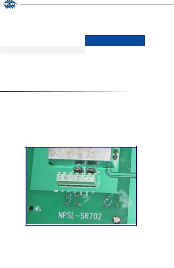
2.7. Load Cell Connection
Description |
CN6 |
|
|
EXCITATION (+) |
E+ |
|
|
SENSE (+) |
SEN+ * |
SENSE (-) |
SEN- * |
EXCITATION (-) |
E- |
SIGNAL (-) |
S- |
SIGNAL (+) |
S+ |
SHIELD |
Chassis |
|
|
* Sense jumpers are installed on the board from the factory. If sense leads are utilized, remove the jumpers by installing the jumper on one pin only for each jumper.
08/13 |
12 |
51219 -- Rev. 6 |

Section 2: Installation
2.8. Load factory defaults
To load the factory defaults in the instrument, perform the following:
1.With the power removed from the instrument, remove the jumper, JP3, inside the instrument. This will permit access to the save menu.
2.Press and hold any one of the following keys  ,
,  ,
,  , or
, or  while turning the scale ON. The display will indicate , continue to hold keys until is shown on the LCD display.
3.Press  key to scroll until the menu is reached.
4.Press  key to select the setting.
5.In the menu, press  key to scroll and select .
6.Press  key to choose the setting.
7.will reset the scale and load the factory default settings.
8.The unit is ready to be configured and calibrated. Refer to the appropriate sections to program and calibrate the instrument.
08/13 |
13 |
51219 -- Rev. 6 |

Section 3: Programming
3.1. Settings
1. Press and hold any one of the following keys  ,
,  ,
,  , or
, or
 while turning the scale ON. is shown on the LCD display.
2.Press  key to scroll among the , , , andmenus.
3.Select , press the  key to enter General Settings menu.
Press the  key to scroll among the settings. Press the
  key to confirm selection.
4. Select , press the  key to enter the Print Settings menu.
Press the  key to scroll among the settings. Press the
  key to confirm selection.
5. Select , press the  key to enter RS-232 Settings menu.
Press the  key to scroll among the settings. Press the
  key to confirm selection.
7. Select , press the  key to enter the Save Settings menu.
Press the  key to scroll among the settings. Press the
  key to confirm selection.
Note:
To access or , the JP3 jumper must be removed from the PCB first. Place the JP3 jumper back when configuration and calibration is complete. All other programming may be accomplished in this secured programming area also.
08/13 |
14 |
51219 -- Rev. 6 |

Section 3: Programming
3.2. - General Settings
In the General Settings menu, press the  key to enter the menu and press the
 key to toggle among the options, and the
  key to confirm.
1. – Sleep Mode Setting
|
Display |
|
Descriptions |
|
|
|
|
|
|
Disable auto shutdown function. |
|
|
|
|
|
|
|
|
If there is no operation, the scale will enter |
|
|
sleep mode in 5 minutes. |
|
|
|
|
|
|
|
|
|
|
|
|
If there is no operation, the scale will enter |
|
|
sleep mode in 10 minutes. |
|
|
|
|
|
|
|
|
|
|
|
|
If there is no operation, the scale will enter |
|
|
sleep mode in 20 minutes. |
|
|
|
|
|
|
|
|
|
|
|
|
If there is no operation, the scale will enter |
|
|
sleep mode in 30 minutes. |
|
|
|
|
|
|
|
|
|
|
|
|
If there is no operation, the scale will enter |
|
|
sleep mode in 60 minutes. |
|
|
|
|
|
|
|
|
|
08/13 |
15 |
51219 -- Rev. 6 |

Section 3: Programming
3.2 Set-up – General Settings, continued
2. - Backlight Setting
|
Display |
|
Descriptions |
|
|
|
|
|
|
Disable the backlight function. |
|
|
|
|
|
|
|
Enable the backlight function. |
|
|
|
|
|
|
|
|
Automatic backlight when there is load on the weighing |
|
|
pan. |
|
|
|
|
|
|
|
|
|
3. - Auto Tare Setting
Display |
Descriptions |
|
|
|
Disable Auto Tare operation |
|
|
|
Tare when the scale is stable. |
|
|
4. – Display Rate Setting
Display |
Descriptions |
|
|
|
The display refreshes at 0.05 sec. |
|
|
|
The display refreshes at 0.1 sec. |
|
|
|
The display refreshes at 0.2 sec. |
|
|
|
The display refreshes at 0.5 sec. |
|
|
|
The display refreshes at 1 sec. |
|
|
08/13 |
16 |
51219 -- Rev. 6 |

|
|
|
Section 3: Programming |
|
||
3.2 Set-up – General Settings, continued |
|
|
|
|||
5. – Check Weigh Hi Beep Setting |
|
|
|
|||
Display |
Explanation |
|
|
|
||
|
|
|
|
|
|
|
|
|
Disable Hi alarm sound. |
|
|
|
|
|
|
|
|
|
|
|
|
|
Set Hi alarm sound as continual short beeps. |
|
|
|
|
|
|
|
|
|
|
|
|
|
Set Hi alarm sound as continual long beeps. |
|
|
|
|
|
|
|
|
|
|
|
6. – Check Weigh Lo Beep Setting |
|
|
|
|||
Display |
Descriptions |
|
|
|
||
|
|
|
|
|
|
|
|
|
Disable Lo alarm sound. |
|
|
|
|
|
|
|
|
|
|
|
|
|
Set Lo alarm sound as continual short beeps. |
|
|
|
|
|
|
|
|
|
|
|
|
|
Set Lo alarm sound as continual long beeps. |
|
|
|
|
|
|
|
|
|
|
|
7. – Normal Operation Beep Setting |
|
|
|
|||
Display |
Descriptions |
|
|
|
||
|
|
|
|
|
|
|
|
|
Disable alarm sound. |
|
|
|
|
|
|
|
|
|
|
|
|
|
Enable alarm sound. |
|
|
|
|
|
|
|
|
|
|
|
8. ! – Year Setting |
|
|
|
|||
Display |
Descriptions |
|
|
|
||
|
|
|
|
|
||
|
|
|
The flashing digit can be changed by pressing the |
|
||
|
|
|
B/G/NET key to change the value. Pressing the Units key |
|
||
XX |
|
|||||
moves the flashing digit. Pressing the Zero key accepts |
|
|||||
|
|
|
|
|||
|
|
|
the value. |
|
|
|
|
|
|
|
|
||
9. – Date Setting |
|
|
|
|||
Display |
Descriptions |
|
|
|
||
|
|
|
|
|
||
|
|
|
The first set of numbers is the month, and the next set of |
|
||
|
|
numbers is the day. Using the same method as above, |
|
|||
|
|
|||||
|
|
|
change the date as needed. |
|
|
|
|
|
|
|
|
|
|
|
|
|
|
|
|
|
08/13 |
|
|
17 |
51219 -- Rev. 6 |
|
|

Section 3: Programming
3.2 Set-up – General Settings, continued
7. M – Time Setting
Display |
Descriptions |
|
|
Even though there are only 5 digits displayed, there are 3 sets (6 digits) to be entered for the date. HH.MM.SS and the time are entered using the 24-hour format, however it
will print in the AM/PM format. 3:49 PM would be entered " 15.49.00. The first set of numbers is the hour, the second set of numbers is the minutes, and the final set of numbers
is the seconds. Pressing the Units key will scroll the display to the 6th digit. Use the standard method for changing the digits to the appropriate numbers.
3.3. – Print Settings
In the Print Settings menu, press the  key to toggle among the
options, and press the  key to enter the menu. Press the
  key to confirm your setting and go to the next option.
1. - Print Function
|
Display |
Descriptions |
|
|
|
|
|
|
|
Print function is disabled. |
|
|
|
|
|
|
|
Press the Print key to print weight data. |
|
|
|
|
|
|
# |
|
Print the weight data automatically when the scale |
|
|
is stable. |
|
|
|
|
|
|
M$ |
|
Send weight data to remote display continuously. |
|
|
This output is fixed at 19200, 8, None, and 1. |
|
|
|
|
|
|
%% |
|
Sends weight data upon the instrument receiving |
|
|
a <CR>. |
|
|
|
|
|
|
|
Remote display when connected to an FB2500 |
|
|
|
|
|
|
|
Remote display when connected to an FB2250 |
|
|
|
|
|
|
|
Remote display when connected to an FB1100 |
|
|
|
|
|
Note:
New selections for Remote Display were added to software Rev 1.8. Please see Appendix IV for complete list of prompts and features.
The Remote Display feature of the FB1100 only works with pounds or kilograms.
08/13 |
18 |
51219 -- Rev. 6 |

Section 3: Programming
3.3 Print Settings, continued
2. - Print Data
Display |
|
|
Descriptions |
|
|
|
|
|
|
|
Print Gross weight only. |
|
|
|
|
|
|
|
Print Gross weight and net weight. |
|
|
|
|
3. - Print Time and Date |
|||
Display |
|
|
Descriptions |
|
|
|
|
! |
|
|
Selecting YES will print the time and date along with the |
|
|||
|
weight. Pressing the B/G / NET button toggles between YES |
||
|
|
|
and no, and pressing the Zero key will save the selection. |
|
|
|
|
|
|
|
|
3.4. – RS-232 Settings
In the RS-232 Settings menu, press the  key to toggle among the
options, and press the  key to enter the menu. Press the
  key to confirm your setting and go to the next option.
1. &- Baud Rate Settings
Display |
Descriptions |
|
Set the baud rate to 1200. |
|
|
" |
Set the baud rate to 2400. |
|
|
"8 |
Set the baud rate to 4800. |
|
|
( |
Set the baud rate to 9600. |
|
|
( |
Set the baud rate to 19200. |
|
|
8" |
Set the baud rate to 38400. |
|
|
) |
Set the baud rate to 57600. |
|
|
|
Set the baud rate to 115200. |
|
|
08/13 |
19 |
51219 -- Rev. 6 |

Section 3: Programming
3.4. – RS-232 Settings, continued
2. - Parity Settings
Display |
Descriptions |
|
) |
Set to 7 data bits, even parity, and 1 stop bit |
|
|
|
|
) |
Set to 7 data bits, odd parity, and 1 stop bit |
|
|
|
|
) |
Set to 7 data bits, no parity, and 2 stop bits |
|
|
|
|
8 |
Set to 8 data bits, no parity, and 1 stop bit |
|
|
|
|
8 |
Set to 8 data bits, even parity, and 1 stop bit |
|
|
|
|
8 |
Set to 8 data bits, odd parity, and 1 stop bit |
|
|
|
|
) |
Set to 7 data bits, odd parity, and 2 stop bit |
|
|
|
|
3.5. Exit Settings Menus
When programming is complete and changes have been saved, exit the program by pressing  . Press
  to return to weighing.
3.6. – Scale Settings
With the power removed from the instrument, remove the jumper, JP3, inside the instrument. This will permit access to the configuration menu.
Software Versions 1.6 and higher
Press and hold any one of the following keys  ,
,  ,
,  , or
, or  while turning the scale ON. The display will indicate , continue to
hold keys until is shown on the LCD display. Press  key to scroll to the menu.
08/13 |
20 |
51219 -- Rev. 6 |
Section 3: Programming
3.6 Scale Settings, continued
1. –Weight Unit Settings
|
Display |
Descriptions |
|
|
|
|
|
% |
|
Sets the instrument primary of measure to lb. |
|
|
|
|
|
|
K* |
Sets the instrument primary of measure to kg. |
|
|
|
|
|
|
2. + Division Settings |
||
|
Display |
Descriptions |
|
|
|
|
|
|
|
|
Set the instrument to 0.00001 division size. |
|
|
(Only available when is set to kg. ) |
|
|
|
|
Available in software revisions 1.6 and lower only. |
|
|
|
Set the instrument to 0.00002 division size. |
|
|
Available in software revisions 1.6 and lower only. |
|
|
|
|
|
|
|
|
Set the instrument to 0.00005 division size. |
|
|
Available in software revisions 1.6 and lower only. |
|
|
|
|
|
|
|
Set the instrument to 0.0001 division size. |
|
|
|
|
|
|
|
Set the instrument to 0.0002 division size. |
|
|
|
|
|
|
|
Set the instrument to 0.0005 division size. |
|
|
|
|
|
|
|
Set the instrument to 0.001 division size. |
|
|
|
|
|
|
|
Set the instrument to 0.002 division size. |
|
|
|
|
|
|
|
Set the instrument to 0.005 division size. |
|
|
|
|
|
|
|
Set the instrument to 0.01 division size. |
|
|
|
|
|
|
|
Set the instrument to 0.02 division size. |
|
|
|
|
|
|
|
Set the instrument to 0.05 division size. |
|
|
|
|
|
08/13 |
21 |
51219 -- Rev. 6 |
 Loading...