


Operator Manual
FB2255 Series Instrument
PC2255
PC Software Utility Program
7 |
8 |
9 |
|
|
|
|
|
|
MENU |
|
4 |
5 |
6 |
|
|
1 |
2 |
3 |
B/G |
|
|
|
|
|
|
|
0 |
ENTER |
NET |
7 |
8 |
9 |
|
|
|
|
|
|
MENU |
|
4 |
5 |
6 |
|
|
1 |
2 |
3 |
B/G |
|
|
|
|
|
|
|
0 |
ENTER |
NET |
© 2012-2013 by Fairbanks Scales, Inc. |
51297 |
All rights reserved |
Rev. 1 01/2013 |

Amendment Record
FB2255
Document 51297
Manufactured by Fairbanks Scales Inc.
821 Locust
Kansas City, Missouri 64106
Created |
07/2012 |
Revision 1 |
01/2013 |
Disclaimer
Every effort has been made to provide complete and accurate information in this manual. However, although this manual may include a specifically identified warranty notice for the product, Fairbanks Scales makes no representations or warranties with respect to the contents of this manual, and reserves the right to make changes to this manual without notice when and as improvements are made.
It is the responsibility of the requesting party to develop, maintain, install, and connect networking devices and general network connectivity as it applies to the originating party’s network. No warranty or guarantee, expressed or implied, concerning the network, its design, its installation, or operational characteristics has been offered by Fairbanks Scales. Fairbanks Scales shall not be liable for any loss, damage, cost of repairs, incidental or consequential damages of any kind, whether or not based on express or implied warranty, contract, negligence, or strict liability arising in connection with the design, development, installation, or use of an intended network.
The Bluetooth® word mark and logos are owned by the Bluetooth SIG, Inc. and any use of such marks by Fairbanks Scales is under license. Other trademarks and trade names are those of their respective owners.
© Copyright 2012-2013
This document contains proprietary information protected by copyright. All rights are reserved; no part of this manual may be reproduced, copied, translated or transmitted in any form or by any means without prior written permission of the manufacturer.
01/13 |
3 |
51297 Rev. 1 |

Table of Contents
SECTION 1: GENERAL INFORMATION ................................................................... |
7 |
|||
1.1. |
Model Descriptions ................................................................................................... |
7 |
||
1.2. |
Main Product Features ............................................................................................. |
7 |
||
1.3. |
Specifications ........................................................................................................... |
8 |
||
1.3.1. |
Instrument Approvals ................................................................................................... |
8 |
||
1.3.2. |
Basic Specifications ..................................................................................................... |
8 |
||
1.3.3. |
Standard Settings......................................................................................................... |
9 |
||
1.3.4. |
Weight Accumulator ..................................................................................................... |
9 |
||
1.3.5. |
Outputs ........................................................................................................................ |
9 |
||
1.3.6. |
PC2255........................................................................................................................ |
9 |
||
1.3.7. |
Power Requirements.................................................................................................... |
9 |
||
1.3.8. |
DC Models ................................................................................................................. |
10 |
||
1.3.9. |
Out of Range Warnings .............................................................................................. |
10 |
||
1.3.10. |
External Printers ........................................................................................................ |
10 |
||
1.3.11. |
Environment............................................................................................................... |
10 |
||
1.4. |
Accessories ............................................................................................................ |
11 |
||
1.5. |
AC Operation.......................................................................................................... |
12 |
||
1.6. |
Powering up the FB2255 ........................................................................................ |
12 |
||
SECTION 2: USER OPERATIONS ......................................................................... |
13 |
|||
2.1. |
Front Panel Key Functions...................................................................................... |
13 |
||
2.2. |
Front Panel Programming Parameters.................................................................... |
14 |
||
2.2.1. |
Setting the Time ......................................................................................................... |
14 |
||
2.2.2. |
Setting the Date ......................................................................................................... |
14 |
||
2.2.3. |
Checking Power Supply / Battery Voltage................................................................... |
15 |
||
2.2.4. |
Programming the Sleep Function ............................................................................... |
15 |
||
2.3. |
Operating Procedures............................................................................................ |
15 |
||
2.4. |
Gross, Tare and Net Weight ................................................................................... |
16 |
||
2.5. |
Basic Weighing....................................................................................................... |
16 |
||
2.6. |
Gross Weighing ...................................................................................................... |
17 |
||
2.7. |
Net Weighing .......................................................................................................... |
17 |
||
2.8. |
Gross/Tare/Net Weighing ....................................................................................... |
17 |
||
2.9. |
Weight Accumulation .............................................................................................. |
18 |
||
2.10. Number of Accumulations...................................................................................... |
18 |
|||
2.11. Clearing the Accumulators...................................................................................... |
18 |
|||
2.12. Piece Counting ....................................................................................................... |
19 |
|||
2.13. Piece Count and Total ............................................................................................ |
20 |
|||
2.14. Peak Weight ........................................................................................................... |
21 |
|||
SECTION 3: SERIAL COMMUNICATION WIRING ................................................. |
22 |
|||
3.1. |
JP3 Jumper Configuration) ..................................................................................... |
22 |
||
3.2. TB4 Wiring connections, COM1 (A), COM2 (B), and COM2 (C) ............................. |
23 |
|||
3.3. TB5 Remote Switch Inputs ..................................................................................... |
23 |
|||
3.4. Remote Display Active Keys .................................................................................. |
24 |
|||
|
|
|
|
|
01/13 |
|
4 |
51297 Rev. 1 |
|

Table of Contents
SECTION 4: INPUT / OUTPUT................................................................................ |
25 |
||
4.1. |
3550 Tape Printer................................................................................................... |
25 |
|
4.2. |
Okidata 186 T Form Printer .................................................................................... |
25 |
|
4.3. |
Okidata 420 Form Printer........................................................................................ |
30 |
|
4.4. |
TM-U295 Ticket Printer........................................................................................... |
33 |
|
4.5. |
TM-U590 Ticket Printer........................................................................................... |
33 |
|
4.6. |
Remote Display ...................................................................................................... |
34 |
|
4.6.1. Programming the 4-20mA Analog Output mode.......................................................... |
35 |
||
4.6.2. Programming the 4mA Weight Value.......................................................................... |
35 |
||
4.6.3. Programming the 20mA Weight Value ........................................................................ |
35 |
||
SECTION 5: FIELDBUS/BLUETOOTH ................................................................... |
36 |
||
5.1. |
Fieldbus Installation ................................................................................................ |
36 |
|
5.2. |
Fieldbus Connections ............................................................................................. |
37 |
|
5.2.1. |
Overview of Terms ..................................................................................................... |
37 |
|
5.2.2. |
DeviceNet (29578) ..................................................................................................... |
39 |
|
5.2.3. |
ControlNet (31979)..................................................................................................... |
41 |
|
5.2.4. |
Profibus (29576) ........................................................................................................ |
43 |
|
5.2.5. Ethernet / IP Diagnostic LEDs .................................................................................... |
45 |
||
5.3. |
Bluetooth® Technology Device................................................................................ |
46 |
|
SECTION 6: PC2255 UTILITY SOFTWARE ........................................................... |
49 |
||
6.1. |
Introduction............................................................................................................. |
49 |
|
6.2. |
Communication Settings......................................................................................... |
49 |
|
6.3. |
Communication Files .............................................................................................. |
51 |
|
6.4. |
Menu Bar................................................................................................................ |
51 |
|
6.5. |
Configuration .......................................................................................................... |
53 |
|
6.6. |
Calibration .............................................................................................................. |
54 |
|
6.7. |
Fieldbus / 4-20 mA.................................................................................................. |
54 |
|
6.8. |
Custom Output – Settings....................................................................................... |
58 |
|
6.9. Custom Output – Load............................................................................................. |
58 |
||
6.10. Custom Output – Build............................................................................................ |
59 |
||
6.11. Custom Output – Tokens ........................................................................................ |
60 |
||
6.12. Custom Output – Weights ...................................................................................... |
61 |
||
6.13. Formatting Tickets .................................................................................................. |
62 |
||
6.14. Printed Examples.................................................................................................... |
63 |
||
SECTION 7: SERVICE AND MAINTENANCE ........................................................ |
64 |
||
7.1. Troubleshooting the Instrument................................................................................ |
64 |
||
7.2. |
Battery Installation .................................................................................................. |
64 |
|
01/13 |
5 |
51297 Rev. 1 |

Table of Contents
APPENDIX I: DATA OUTPUT FORMATS ............................................................... |
65 |
|
A. |
General Notes ........................................................................................................ |
65 |
B. |
Fairbanks/ Toledo Continuous Output..................................................................... |
65 |
C. |
Cardinal 738 Continuous Scoreboard Output.......................................................... |
68 |
D. |
Weightronics WI-120 Continuous Output ................................................................ |
68 |
E. |
Condec Continuous Output..................................................................................... |
69 |
F. |
Demand Output ...................................................................................................... |
69 |
G. |
Continuous Output.................................................................................................. |
70 |
H. |
PLC ........................................................................................................................ |
71 |
I. |
UPS........................................................................................................................ |
72 |
J. |
P Ship..................................................................................................................... |
73 |
APPENDIX II: REMOTE PC COMMANDS ............................................................... |
75 |
|
APPENDIX III: FB2255 REMOTE DISPLAY WIRING.............................................. |
77 |
|
APPENDIX VI: FB2255 REMOTE DISPLAY ACTIVE KEYS ................................... |
78 |
|
01/13 |
6 |
51297 Rev. 1 |

Section 1: General Information
1.1. Model Descriptions
The FB2255 is a general purpose weighing instrument that can be used with a wide variety of platforms and load receivers, and is available in eight (8) different configurations.
MODEL |
PART NO. |
∙ FB2255-1 Series ABS, AC Power |
32351 |
|
|
∙ FB2255 Series ABS, AC/Battery Power with Bracket |
32449 |
|
|
∙ FB2255-2 Series SS, AC Power |
32352 |
|
|
∙ FB2255 Series SS, AC/Battery Power with Bracket |
32450 |
|
|
∙ FB2255 Series SS, AC Power, No Bracket |
32451 |
|
|
∙ FB2255 Series SS, AC/Battery Power, No Bracket |
32452 |
|
|
∙ FB2255 Series SS, AC Power, No Bracket, IP69K |
32453 |
|
|
∙ FB2255-K Series SS, AC Power, IP69K |
32352 |
|
|
1.2. Main Product Features
Major features of the Instrument include the following.
∙Push-button programming and calibration.
∙Program data is stored in battery supported ram and backed up in flash memory.
–The battery should be replaced every twelve (12) months.
∙The FB2255 series instrument features a large one inch (1”) green backlit LCD weight display, which can be tilted up or down to accommodate different lighting conditions.
–Microprocessor controlled design allows the instrument to be rapidly programmed at installation to meet the specific requirements of the application.
∙The obtainable accuracy meets Handbook 44 requirements, and the instrument is approved for commercial application up to 10,000 divisions.
–A maximum of 100,000 displayed divisions can be programmed for noncommercial applications.
∙A computer utility software program PC2255 is available, downloaded from Fairbanks Intranet for programming using the computer, and is required for certain features such as custom ticket formatting.
01/13 |
7 |
51297 Rev. 1 |

Section 1: General Information
1.2.Main Product Features, Continued
∙The PC2255 software utility program can also upload and modify the instruments set-up, configuration, and calibration.
–Saved information can be downloaded from a computer to the FB2255 Series in the event of a catastrophic failure.
∙The instrument provides two (2) serial communication ports to provide communication to various types of peripheral devices for RS232, RS422, RS485, and 20mA data outputs.
∙Optional accessories include a 4-20 mA Analog Output, a Bluetooth® serial adapter, and three different fieldbus devices; Profibus®, DeviceNet™, and Ethernet/IP.
1.3.Specifications
|
1.3.1. |
INSTRUMENT APPROVALS |
|
|
|
∙ |
CC |
09-023 |
|
|
|
∙ |
MC |
AM-5720 |
∙ |
ETL |
ETL Listed |
|
|
|
∙ Conforms to ANSI/UL STD 60950-1 |
||
∙ Certified to CAN/CSA C22.2 STD NO. 60950-1-03 |
||
|
|
|
1.3.2. BASIC SPECIFICATIONS
∙ |
ENCLOSURE |
|
ABS, Black NEMA 1, Stainless Steel NEMA 4X Desk and Wall |
|
Mount |
||
|
|
|
|
|
|
|
|
∙ |
DISPLAY |
|
6-digits, One inch (1”) LCD, Green Backlight |
∙ |
FRONT PANEL KEYS |
|
On/Off, Units, Zero, B/G, Net, Tare and Print |
|
|
|
|
∙ |
UNITS |
|
lbs., oz, kg, g and lbs/oz, or custom |
∙ |
GRADUATION SIZE |
|
0.0001 to 50 |
|
|
|
|
∙ |
AD CONVERSION |
|
66 per second |
∙ |
LOAD CELL EXCITATION |
|
5 Volts DC |
|
|
|
|
∙ |
SENSITIVITY |
|
1µv/d (microvolt/division) |
∙ |
LOAD CELLS |
|
Eight (8) 350 ohm or Sixteen (16) 1000 ohm |
|
|
|
|
∙ |
DISPLAYED DIVISIONS |
|
10,000d Commercial and 100,000d Non-Commercial |
∙ |
CAPACITIES |
|
Programmable to 999999 |
|
|
|
|
01/13 |
8 |
51297 Rev. 1 |

Section 1: General Information
1.3.Specifications, Continued
1.3.3. STANDARD SETTINGS
∙ |
Zero Range |
Off, 2 % or 100% |
|
|
|
∙ |
Auto Zero Tracking |
OFF, 0.5, 1 or 3 divisions |
∙ |
Balance |
OFF, 0.5, 1 or 3 divisions |
|
|
|
∙ |
Filter |
Slow, Animal, Standard, and Fast |
∙ |
Display Update Rate |
0.2, 0.4, and 0.8 seconds |
|
|
|
|
1.3.4. |
WEIGHT ACCUMULATOR |
|
|
|
|
|
∙ |
Capacity |
|
999,999 Weight Units |
|
|
|
– Printed or viewed. |
|
|
|
|
|
1.3.5. |
OUTPUTS |
|
|
|
|
|
∙ |
PORT 1 |
|
Bidirectional Serial Port. Settings include OFF, RS232, RS422, |
|
|
|
and RS485. RS232 has 30+ updates a second |
|
|
|
|
∙ |
PORT 2 |
|
Port 2 is used to interface to the PC2255 program, |
|
|
|
|
|
|
|
OR, |
|
|
|
Provide 20 mA passive, RS232, RS422,or RS485. |
|
|
|
|
1.3.6.PC2255
∙Computer software utility program is available for your local Fairbanks Representative.
∙PC2255 is required for setting certain aspects of programming, such as custom Units and custom ticket formatting.
1.3.7.POWER REQUIREMENTS
∙117 volts AC +/- 10 %
∙220 volts AC +/- 10 %
∙< 0/2 volts AC between Neutral and Ground
∙1.5 watts maximum
∙The FB2255 is designed to operate from 80 to 260 volts AC, 50 to 60 Hertz
01/13 |
9 |
51297 Rev. 1 |

Section 1: General Information
1.3.Specifications, Continued
1.3.8. DC MODELS
∙ |
Batteries |
Five (5) Size “D” Alkaline batteries @ 1.5 Volts DC each. |
|
|
|
|
|
|
∙ |
Battery Life |
∙ Up to forty (40) Hours or greater with a maximum load of 4, 350 load |
|
|
|
|
|
cells and backlighting enabled. |
|
|
∙ Battery usage time can be adversely affected by battery storage, |
|
|
battery capacity and battery brand. |
|
|
∙ To maximize battery life, Serial Ports 1 and 2 should be switched |
|
|
OFF, if not used. |
|
|
|
∙ |
Internal Battery |
∙ Should be replaced every 12 months using Panasonic CR 1220 3V or |
|
|
equivalent. |
|
|
|
1.3.9. OUT OF RANGE WARNINGS
∙ |
HiCAP |
Scale input is over capacity |
|
|
|
∙ - - - - - - - |
Displayed weight exceeds 6 digits |
|
∙ |
Sleep Mode |
Settings include OFF, 1, 2, 5, 10, 20, and 30 minutes |
|
|
|
∙ |
Time and Date |
Battery Maintained |
|
|
|
1.3.10.EXTERNAL PRINTERS
∙Citizens IDP 3550 Tape Printer
∙Okidata 184 & 186 Serial Form Printer
∙Okidata 420 Serial Form Printer
∙Epson Models TM-U295 and TM-U590 Ticket Printers
1.3.11.ENVIRONMENT
∙ |
Temperature |
-10ºC to + 40ºC |
(+14ºF to + 104ºF) |
|
|
|
|
∙ |
Storage Temp. |
-40ºC to + 60ºC |
(-40ºF to + 140ºF) |
|
|
|
|
01/13 |
10 |
51297 Rev. 1 |
Section 1: General Information
1.4. |
|
Accessories |
|
|
|
|
||
|
Optional accessories include the following. |
|
|
|||||
|
|
|
|
|
|
|
|
|
|
|
FIELDBUS DEVICES |
|
|
|
|
||
|
|
∙ |
DeviceNet™ |
|
∙ ControlNet™ |
∙ |
Profibus® |
∙ Ethernet/IP |
|
|
|
|
|
||||
|
|
4-20 MA ANALOG CURRENT LOOP OUTPUT |
|
|||||
|
|
∙ |
16 bit Resolution and Monotonicity |
∙ |
0.01% Non-Linearity |
|
||
|
|
|
|
|
|
|||
|
|
∙ |
Isolated 4mA to 20mA |
∙ |
Front Panel Programmable or via PC2255 utility |
|||
|
|
|
|
|
|
|
software program |
|
|
|
|
|
|
|
|
|
|
BLUETOOTH® TECHNOLOGY INTERFACE
∙Utilizes either Port 1 or Port 2 Serial Output. RS232 serial Interface to Bluetooth Interface. Range 100 meters (328 feet).
∙The Bluetooth option will operate either as a Client or Server depending on which device the FB2255 is connected.
–If connected to a printer, the FB2255 will be a Server.
–If connected to a PC, the Instrument will be a Client.
01/13 |
11 |
51297 Rev. 1 |

Section 1: General Information
1.5. AC Operation
The FB2255 is designed to operate from 80 to 260 volts AC, 50 to 60 Hertz.
∙117 Volt AC Operation
∙FB2255 is factory wired for 117 VAC and requires a three prong grounded outlet.
FB2255 ABS Power Cord |
Connection |
|
|
|
|
Brown/Black |
AC (Hot) |
117 VAC |
|
|
|
Blue/White |
ACC (Neutral) |
0 VAC |
|
|
|
Green/Green-Yellow |
Ground |
|
|
|
|
∙220 Volt AC Operation
The FB2255 has Auto Switching capability.
∙ Rewire the power cord according to the following diagram.
∙
1.6.Powering up the FB2255
1.Press and hold the ON / OFF Key for one to two (1 – 2) seconds.
–The Instrument will display “888888”, then a “1234567890” character display moving from right to left, followed by the revision of software.
–Upon completing the warm-up, the FB2255 will display the actual weight on the scale.
2.Press and hold the ON / OFF Key for one to two (1 – 2) seconds to turn off the FB2255.
01/13 |
12 |
51297 Rev. 1 |
Section 2: User Operations
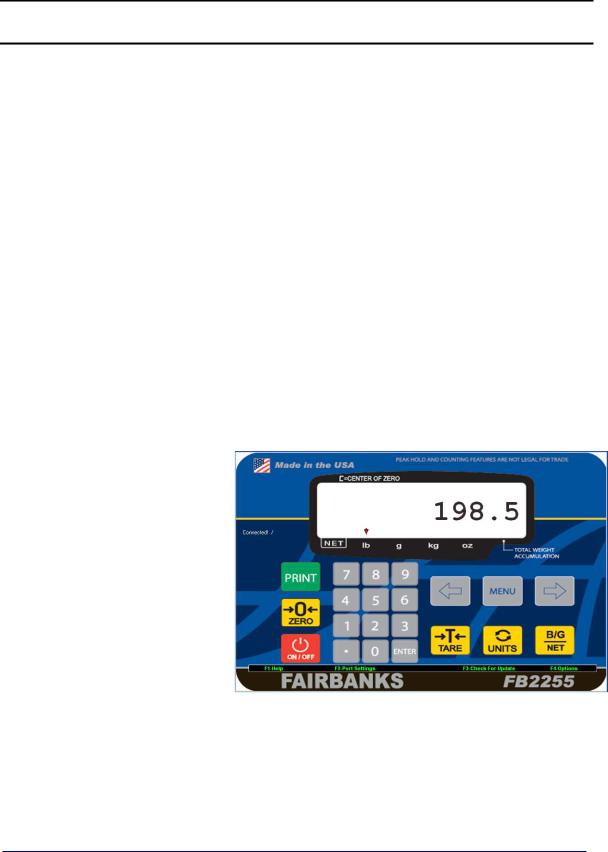
2.1. Front Panel Key Functions
ON/OFF |
Turns the Instrument on or off. |
|
|
UNITS |
Switches between pre-programmed selectable weight units. |
ZERO |
Sets the display to zero, programmable: 2% or 100% of capacity. |
|
|
B/G – NET |
Toggles between Gross and Net weights |
|
∙ This apples only if a Tare Value has been entered greater than ZERO. |
TARE |
Automatically tares off displayed weight when key is pressed. |
|
|
Simple RS232 output when key is pressed. |
|
0-9 |
Used for Programming and inputting manual tares. |
MENU |
Gains access to the sub-menus in the Configuration Mode. |
ARROW |
Used for scrolling through the menu selections. |
KEYS |
|
|
|
Depending on programmed selection, Tare Weight amount will do one of the following.
∙Be retained for reuse until changed, or if power is removed.
OR…
∙Automatically clear when
Gross Weight returns to
ZERO.
01/13 |
13 |
51297 Rev. 1 |

Section 3: Serial Communication Wiring
2.2. Front Panel Programming Parameters
Follow these steps to program the Instrument.
2.2.1.SETTING THE TIME
Press, hold
PRINT for
3 seconds
1.Press and hold the PRINT key for three (3) seconds.
–The display momentarily displays Set-ti, then shows the current time in HHMMSS.
2.Press the RIGHT ARROW key will scroll to “12hr A”, “SetdA”, and then back to Weigh Menu.
3.When the current time setting is displayed, press the MENU key.
–The most significant digit will erase.
4.Key the new time setting with the 0-9 keys.
5.Press ENTER.
6.At the “12hr A” prompt, press the MENU key.
7.Use the ARROW KEYS to toggle through the option noted below.
∙12hr A – 12 hour clock, currently AM.
∙12hr P – 12 hour clock, currently PM.
∙24 hour – Military time (1:00 PM = 1300 hours).
8. Press ENTER to save the setting.
2.2.2. SETTING THE DATE
∙Set-dA displays, followed by the current date setting.
∙Date is entered in the MM-DD-YY format.
1.Press Menu.
–The first two digits will blink.
–The most significant digit will erase.
2.Key the new time setting with the 0-9 keys.
3.Press ENTER.
Press RIGHT
ARROW
Press MENU
Enter Time
with
0-9 Keys
Press ENTER
Press MENU
Enter AM, PM,
Mil. Time with
ARROW Keys
Press
ENTER
Press MENU
Enter Date with
0-9 Keys
Press
ENTER
01/13 |
14 |
51297 Rev. 1 |

Section 3: Serial Communication Wiring
2.2.3. CHECKING POWER SUPPLY / BATTERY VOLTAGE
1.Press the TARE key for three (3) seconds.
–The battery current or power supply voltage displays
–8.3 VDC nominal.
2.2.4.PROGRAMMING THE SLEEP FUNCTION
1.Press and hold the BG/Net key for three (3) seconds.
–The display will indicate SLEEP, and then display the current setting.
–This function serves to prolong battery life by turning off the Instrument.
–When there is no activity, the Sleep Mode activates according to the programmed time frame.
–Activity is when weight is applied to the scale exceeding the balance setting, pressing a key, and receiving a polling request on a communication port.
2.Press MENU.
3.Use the Arrow Keys to toggle between the available options.
–Selections in minutes include OFF, 1, 2, 5, 10, 20, 30.
4.Press ENTER to save the setting.
2.3.Operating Procedures
1.Press and hold the ON / OFF Key for two (2) seconds.
–The Instrument will display “888888” , followed by “1234567890” character display moving from right-to-left, then the revision of software.
–Once the warm-up is complete, the FB2255 displays the actual weight on the scale.
2.To turn the FB2255 off, press the ON / OFF key for two (2) seconds.
∙The Zero. Tare and the AZT functions require the displayed weight to be stable before these functions will operate.
∙The weight reading is stable if the variation in weight is less than the programmed
BAL RANGE.
01/13 |
15 |
51297 Rev. 1 |

Section 3: Serial Communication Wiring
2.4. Gross, Tare and Net Weight
There are three terms used when weighing an object’s or load’s amount.
The NET WEIGHT (product only) is the GROSS WEIGHT (total amount) minus the TARE WEIGHT
(container only).
NET WEIGHT = Gross Weight – Tare Weight
NET
G
R
O
S
T S A
R
E
WORKING EXAMPLE
A full can of house paint is an object to be weighed. The empty can is the TARE weight. The paint is the NET weight. Together they equal the GROSS weight.
2.5. Basic Weighing
Follow these steps for Basic Weighing.
1.Empty the platform.
2.Turn the scale ON.
3.Press ZERO.
– When the display indicates “0”, it is ready for use.
01/13 |
16 |
51297 Rev. 1 |

Section 3: Serial Communication Wiring
2.6. Gross Weighing
Follow these steps for Gross Weighing.
1.Press the GROSS/NET key, if required, to set display to GR (gross).
2.Press the ZERO key, if required, to set scale to “0”.
3.Place container/object on scale (Tare weight).
4.Read the Gross Weight on the display.
2.7.Net Weighing
Follow these steps for Net Weighing.
1.Press the GROSS/NET key, if required, to set display to GR (gross).
2.Press the ZERO key, if required, to set scale to “0”.
3.Place container/object on scale (Tare weight).
4.Press the TARE key.
5.Place material in container or add objects (Net weight).
6.Read the Net Weight on the display.
2.8.Gross/Tare/Net Weighing
1.Press the GROSS/NET key to display GR (Gross).
2.Press the ZERO key, if required, to set scale to “0”.
3.Place container/object on scale, noting the weight.
4.Press TARE.
5.Place material in container or add objects.
6.Note the Net Weight on the display.
7.Press the GROSS/NET key to switch to Gross.
8.Read the Gross Weight on the display.
01/13 |
17 |
51297 Rev. 1 |

Section 3: Serial Communication Wiring
2.9.Weight Accumulation
1.Place a weight on the Scale Platform.
2.After the weight is stable, press the B/G NET key until the display alternates between the number of Accumulations "n" and the Accumulated weight.
3.Press the UNITS key to accept the weight, (display will momentarily indicate
“ACCEPt”, or press the B/G NET key to skip and return to the weigh screen.
4.The scale must return to “0” Gross Mode before another accumulation can occur.
5.Repeat steps 1 through 4 for additional accumulations.
2.10.Number of Accumulations
1.Press and hold ZERO for three (3) seconds.
–The display will alternate between the Accumulated Piece Count and the Accumulated Weight for thirty (30) seconds, then return to the Weigh Mode.
2.Press UNITS and exit immediately to the Weigh Mode.
–Pressing the UNITS key will not clear the accumulator.
2.11.Clearing the Accumulators
1.Press and hold the BG/Net key for three (3) seconds.
–The display will indicate “Sleep” and then display the current setting.
2.Press Right Arrow key.
–“CLr.ACC” will display.
3.Press the MENU key, then the Right Arrow key to toggle the available settings.
Available selections include the following settings.
Clr.YES (Clear the Accumulator) CLr. NO (Do not Clear the Accumulator)
4.Press ENTER to enter the selection.
01/13 |
18 |
51297 Rev. 1 |
Section 3: Serial Communication Wiring
2.12. Piece Counting
5.Place the empty weighing container on the Scale Platform.
6.Press TARE.
–This stores the container weight the only, placing the scale in the Net Mode.
–“0 Net Weight” should display on the indicator.
7.Press B/G NET.
–The Display prompts to "Add" a number of sample parts to the container.
8.Pressing the B/G NET key repeatedly prompt the user to; "Add 1", "Add 5", "Add 10", "Add 25", Add 50", or "Add 100" parts.
9.Add the required sample to the container, then press UNITS.
–The Display alternates between indicating the weight and the number of pieces.
10.Add the remaining parts to the container.
–The display will update and continue to alternate between the Weight and Number of Pieces, including the original sample.
11.Press B/G NET.
–Pressing the B/G NET key will skip adding the Current Piece to the Total Register and return to the Weigh Mode.
See the Print Example below.
Place
Container
on Scale
Press TARE
Tare stored.
. Scale in NET
MODE
Press B/G
Select sample size
Add sample.
Press UNITS
Add remaining parts
Press
B/G NET to Exit
NOTES: If the prompts do not occur, clear the Accumulator and start over. The operating mode must be set to PIECE COUNT & TOTAL to function.
01/13 |
19 |
51297 Rev. 1 |

Section 3: Serial Communication Wiring
2.13. Piece Count and Total
This feature enables the FB2255 to count and display the Net Weight of the counted items, and to display the total amount of those items.
1.Place the container on the scale platform.
2.Press TARE to calculate the container weight.
3.The Display should indicate 0 NET WEIGHT.
4.Press the B/G NET key.
5.When the display prompts to "Add", add a number of sample parts to the Container.
6.Press B/G NET repeatedly until the display reads to; "Add 1", "Add 5", "Add 10", "Add 25", Add 50", or "Add 100" parts.
7.Add the required sample to the container.
–The Display will alternate between the Weight and Number of Pieces, including the original sample.
8.Add the remaining parts to the container.
–The Display will update and continue to alternate between the Weight and Number of Pieces, including the original sample.
9.Press B/G NET.
–The Display will alternate between the "Total" legend and the Total Number of Pieces Accumulated.
10.Press UNITS to return to the Weigh Mode.
NOTE: If the prompts do not occur, clear the ACCUMULATOR and start over.
The Operating Mode must be set to Piece Count & Total to function.
To reset Piece Count – see “CLEARING THE ACCUMULATOR”.
01/13 |
20 |
51297 Rev. 1 |
Section 3: Serial Communication Wiring
2.14. Peak Weight
The Peak Weight feature records the heaviest stable or unstable load t placed on the scale, and its time and date.
1.Press and hold ZERO for three (3) seconds.
–The display will alternate between the Peak Weight Value, the time and date for thirty (30) seconds, then return to the Weigh Mode.
2.Press UNITS to end the process. and exit to the Weigh Mode.
–Pressing the UNITS key will not clear the accumulator.
∙Conditional upon programming the Operating Mode to ACCUMULATION,
PIECE COUNT, OR PIECE COUNT and TOTAL.
∙The FB2255 will display total number of Pieces, Weight, and Time-out [thirty (30) seconds].
∙Conditional upon programming the Operating Mode to PEAK HOLD
STABLE or PEAK HOLD UNSTABLE.
∙The FB2255 will display Time, Date, Peak Weight, and Time Out [thirty (30) seconds].
01/13 |
21 |
51297 Rev. 1 |

Section 3: Serial Communication Wiring
|
|
|
|
|
JP3 |
TB2 |
|
|
|
|
|
|
|
|
|
|
TB5 |
INTERNAL PROGRAM |
J11 |
TB4-A |
TB4-C |
TB4-B |
TB3 |
SWITCH |
|
|
|
|
|
|
Printed Circuit Board (31308) |
|
|
||
3.1. JP3 Jumper Configuration)
JP3 |
RS232 |
RS485 |
RS422* |
PORT |
1-2 |
Out |
120 Ohm |
120 Ohm |
COM1 |
|
|
Resistor |
Resistor |
|
|
|
|
|
|
3-4 |
Out |
In |
Out |
COM1 |
5-6 |
Out |
In |
Out |
COM1 |
|
|
|
|
|
7-8 |
Out |
In |
Out |
COM2 |
9-10 |
Out |
In |
Out |
COM2 |
|
|
|
|
|
11-12 |
Out |
120 Ohm |
120 Ohm |
COM2 |
|
|
Resistor |
Resistor |
|
|
|
|
|
|
*Port should be set to RS485.
NOTE: 120 ohm Termination Resistors are required if the receiver is the last node on the network.
01/13 |
22 |
51297 Rev. 1 |

Section 3: Serial Communication Wiring
3.2. TB4 Wiring connections, COM1 (A), COM2 (B), and COM2 (C)
TB4 (A) |
RS232 |
RS485 |
RS422* |
PORT |
1 |
Rx – Receive Data |
(–) RS485 |
RS422 (–) Rx |
COM1 |
|
|
|
|
|
2 |
Tx – Transmit Data |
(–) RS485 |
RS422 (–) Tx |
COM1 |
3 |
CTS – Clear-to-Send |
(+) RS485 |
RS422 (+) RX |
COM1 |
|
|
|
|
|
4 |
GND -- Ground |
GND |
GND |
COM1 |
5 |
RTS – Ready-to-Send |
(+) RS485 |
RS422 (+) Tx |
COM1 |
|
|
|
|
|
TB4 (B) |
RS232 |
RS485 |
RS422* |
PORT |
1 |
Rx – Receive Data |
(–) RS485 |
RS422 (–) Rx |
COM2 |
|
|
|
|
|
2 |
TX – Transmit Data |
(–) RS485 |
RS422 (–) Tx |
COM2 |
3 |
CTS – Clear-to-Send |
(+) RS485 |
RS422 (+) Rx |
COM2 |
|
|
|
|
|
4 |
GND – Ground |
GND |
GND |
COM2 |
5 |
RTS – Ready-to-Send |
RS485 |
RS422 (+) Tx |
COM2 |
|
|
|
|
|
TB4 (C) |
20 MA |
|
RS485 |
RS422 |
|
PORT |
|
1 |
(+) TX – Remote Display |
|
|
|
COM2 |
||
|
Passive, 20 mA Output |
|
|
|
|||
|
|
|
|
|
|
||
2 |
(–) TX – Remote Display |
|
|
|
COM2 |
|
|
|
Passive, 20 mA Output |
|
|
|
|
||
|
|
|
|
|
|
||
3 |
® |
Technology Supply |
|
|
|
|
|
|
(+) 7.5V Bluetooth |
|
|
|
|
||
|
|
|
|
|
|
|
|
*Port should be set to RS485.
3.3. TB5 Remote Switch Inputs
1 |
Ground |
|
|
|
|
2 |
Ground |
|
3 |
Ground |
|
|
|
|
4 |
Connect to ground to perform programmed Print function |
|
5 |
Tare |
Connect to ground to Tare off Gross weight |
|
|
|
6 |
B/G Net |
Connect to ground to Select Gross/Tare displays |
7 |
Zero |
Connect to ground to Zero Platform Weight |
|
|
|
8 |
Units |
Connect to ground to change to alternate weight units |
|
|
|
01/13 |
23 |
51297 Rev. 1 |

Section 3: Serial Communication Wiring
3.4.Remote Display Active Keys
INSTRUMENT |
FB2255 ACTIVE FRONT PANEL KEYS |
FB2200 |
No Active Keys |
|
|
FB2255 |
Units, Zero, Gross Net, Auto Tare, Print |
|
|
FB2255 |
Units, Zero, Gross Net, Auto Tare, Print |
|
|
2300 |
No Active Keys |
|
|
2500 |
No Active Keys |
|
|
2800 |
No Active Keys |
|
|
5200A |
Units, Gross Net |
|
|
01/13 |
24 |
51297 Rev. 1 |
 Loading...