

Page 1

Installation Manual
Omnicell
Model: 9101 FB
Load Cell Only
Some Models
51172
© 2007 by Fairbanks Scales, Inc. Revision 1 09/07
All rights reserved
Page 2

Page 3

Amendment Record
Omnicell 9101 FB
DOCUMENT 51172
Manufactured by Fairbanks Scales Inc.
821 Locust Street
Kansas City, Missouri 64106
Created 08/2007
Revision 0 08/2007 Preliminary Release
Revision 1 09/2007 Documentation Release
09/07 3 51172 Revision 1
Page 4

Disclaimer
Every effort has been made to provide complete and accurate information in this manual. However,
although this manual may include a specifically identified warranty notice for the product, Fairbanks
Scales makes no representations or warranties with respect to the contents of this manual, and
reserves the right to make changes to this manual without notice when and as improvements are
made.
It is the responsibility of the requesting party to develop, maintain, install, and connect networking
devices and general network connectivity as it applies to the originating party’s network. No warranty
or guarantee, expressed or implied, concerning the network, its design, its installation, or operational
characteristics has been offered by Fairbanks Scales. Fairbanks Scales shall not be liable for any
loss, damage, cost of repairs, incidental or consequential damages of any kind, whether or not based
on express or implied warranty, contract, negligence, or strict liability arising in connection with the
design, development, installation, or use of an intended network.
© Copyright 2007
This document contains proprietary information protected by copyright. All rights are reserved; no part
of this manual may be reproduced, copied, translated or transmitted in any form or by any means
without prior written permission of the manufacturer.
09/07 4 51172 Revision 1
Page 5

Table of Contents
SECTION 1: GENERAL INFORMATION ..................................................................6
Description........................................................................................................................... 6
Features..........................................................................................................................................6
Applications..................................................................................................................................... 6
Dimensions (In Inches)................................................................................................................... 7
Wiring .......................................................................................................................................... 7
Specifications ...................................................................................................................... 8
SECTION 2: INSTALLATION.....................................................................................9
General Service Policies ..................................................................................................... 9
Phases of Installation...................................................................................................................... 9
Conferring with Our Client............................................................................................................... 9
Pre-Installation Checklist ..............................................................................................................10
Unpacking..................................................................................................................................... 10
Safety ..........................................................................................Error! Bookmark not defined.
User’s Responsibilities.................................................................................................................. 11
Installation ......................................................................................................................... 12
Basic Assembly Steps .................................................................................................................. 12
Load Cell Placement.....................................................................................................................13
SECTION 3: PARTS.................................................................................................14
Omnicell 9101 FB Complete Units................................................................................................ 14
Load Cells Only............................................................................................................................. 14
Rubber Mounts ............................................................................................................................. 15
Parts Not Supplied with Assembly................................................................................................15
Assembly Units Without Load Cells.............................................................................................. 16
APPENDIX I: OMNICELL CONFIGURATIONS .......................................................18
09/07 5 51172 Revision 1
Page 6

Section 1: General Information
DESCRIPTION
Fairbanks’ Omnicell® 9101 FB Series is a single-ended beam weighing assembly.
It is a cost-effective choice for low capacity, indoor, commercial and non-commercial
weighing applications.
Features
• Low-to-medium weight range Omnicells
• Stainless steel mounting hardware.
• Low profile design.
• Load Cell Types
─ Stainless Steel Load Cell — 50 to 250 lb capacity models.
─ Tool Steel Load Cell — 500 to 2,500 lb capacity models.
• Environmentally protected load cells.
• Mount Construction
─ The top plate is made of neoprene, and it is an isolation/compression mount
that provides for shock absorbsion, thermal expansion/contraction and
compensates for minor misalignment.
─ The base plate is constructed from stainless steel to be extremely durable and
to withstand corrosion.
• Custom capacities and cable lengths available.
®
— 50 to 2,500 lb capacity models.
Applications
• Legal for Trade • Low Capacity • Intrinsically Safe • Conveyor/In-Motion
• Batching • Mixing • Blending • Bins
• Tanks • Hoppers • Vibratory Feeder • Hazardous
Conditions
09/07 6 51172 Revision 1
Page 7
Section 1: General Information
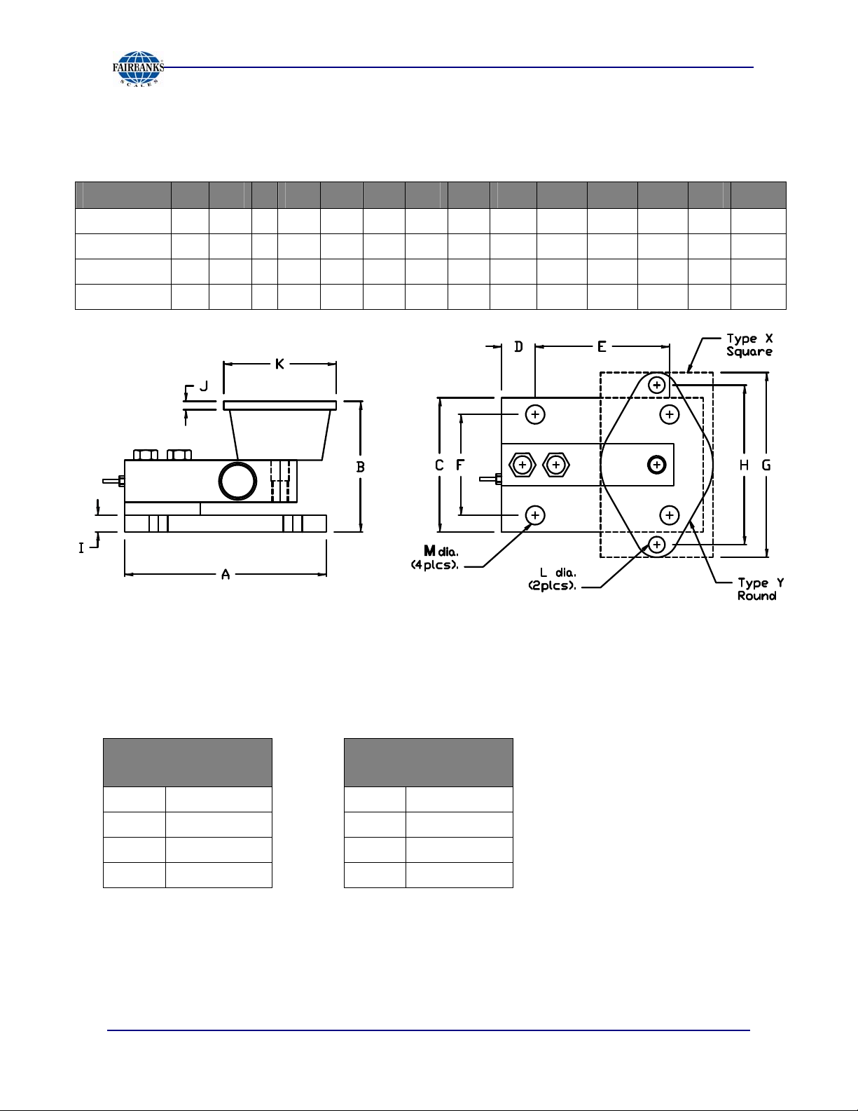
Dimensions (In Inches)
CAPACITY A B C D E F G H I J K L M TYPE
25–250 lbs
500 lbs
1,000 lbs
2,500 lbs
4 3.13 3 0.37 3.25 2.25 3.88 3.00 0.50 0.22 2.38 0.38 0.34
6 3.88 4 1.00 4.00 3.00 5.50 4.13 0.50 0.25 3.38 0.56 0.47
6 4.00 4 1.00 4.00 3.00 5.13 4.13 0.50 0.13 3.00 0.44 0.47
6 4.00 4 1.00 4.00 3.00 6.25 5.00 0.50 0.38 4.62 0.44 0.47
Y
Y
X
X
Wiring
CABLE CODE
50-250 LB
Red (+) Excitation
Black (─) Excitation
Green (+) Signal
White (─) Signal
09/07 7 51172 Revision 1
CABLE CODE
500-2500 LB
Green (+) Excitation
Black (─) Excitation
White (+) Signal
Red (─) Signal
Page 8
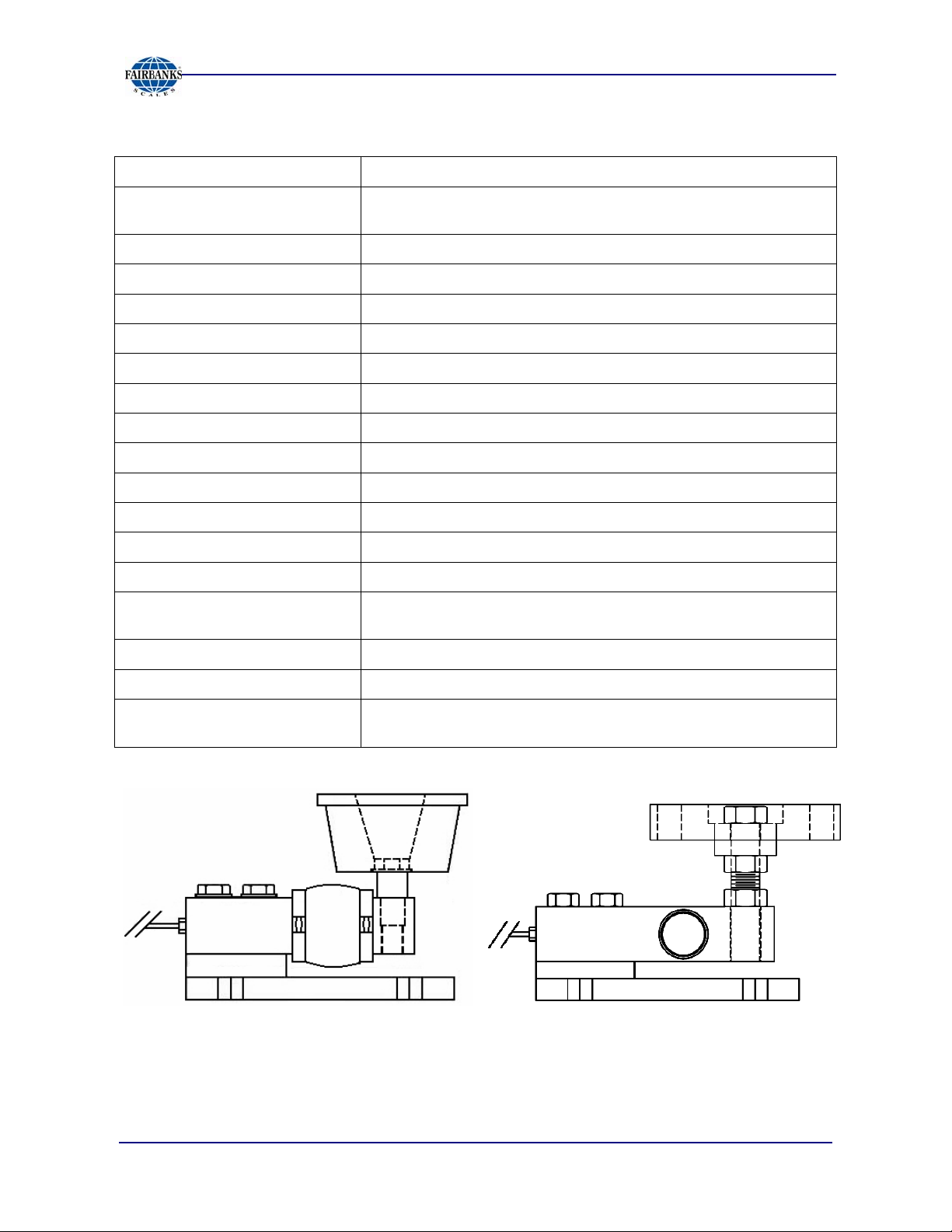
SPECIFICATIONS
Section 1: General Information
Capacities
Mount Construction
Full Scale Output (FSO)
Combined Error (FSO)
Non-Linearity (FSO)
Hysteresis (FSO)
Creep Error (20 min.)
Compensated Temperature
Operating Temperature
Excitation Voltage
Mechanical Overload
Side-load
Reject Ratio
Bridge Resistance
Load Cell Construction
Cable
50, 75, 100, 150, 250, 500, 1,000 and 2,500 lbs.
• Stainless steel Base Plate
• Reinforced Neoprene Top Plate
3.0mV/v ± 0.25%
≤ 0.03%
≤ 0.03%
≤ 0.02%
≤ 0.03%
14° to 104° F (-10° C to 40° C)
-4° to 140° F (-20° – 60° C)
5-15 VDC
• Safe = 150% • Ultimate = 300%
Safe = 100%
500:1
350 ohms nominal
• Stainless Steel 17-4 PH (50-250 Capacity)
• Alloy Tool Steel (500-2,500 Capacity)
20 ft. Polyurethane
Protection
Approvals
IP 66
• Factory Mutual Approved
• NTEP CC #07-009 – Capacities 500 lbs. and greater
Omnicell9101 FB Bending Beam design with
capacities equal to or less than 250 pounds
Omnicell9101 FB
capacities greater than 250 pounds
Shear Beam design with
09/07 8 51172 Revision 1
Page 9

Section 2: Installation
GENERAL SERVICE POLICIES
Phases of Installation
1. Verifying the application.
2. Unpacking & equipment checkout.
3. Installation & adjustments.
4. Customer check-off and site readiness..
Conferring with Our Client
• The lead tech must be prepared to recommend the arrangement of components
which provide the most efficient layout, utilizing the equipment to the best possible
advantage.
• The warranty policy must be explained and reviewed with the customer.
Before the installation is considered complete, the equipment is to
be configured to meet or exceed any applicable weights and
measures requirements.
09/07 9 51172 Revision 1
Page 10

Section 2: Installation
Pre-Installation Checklist
The following points should be checked and discussed with the Area Sales Manager
and/or customer, if necessary, before the technician goes to the site and installs the
equipment.
9 Check the customer's application to make certain it is within
the capabilities and design parameters of the equipment.
9 If the installation process might disrupt normal business
operations, tell the customer and ask that they make ample
arrangements.
9 Is properly-grounded power available at the installation
location?
9 Be sure that the equipment operator(s) are available for training.
9 The service technician must thoroughly review the installation procedures.
9 The service technician reviews the recommended setup with the Area Sales
Manager or Area Service Manager, and together they identify all necessary
variations to satisfy the customer's particular application.
Unpacking
Follow these guidelines when unpacking all equipment:
9 Check in all components and accessories according to the customer's order.
9 Remove all components from their packing material, checking against the invoice
that they are accounted for and not damaged.
Advise the shipper immediately, if damage has occurred.
Order any parts necessary to replace those which have been damaged.
Keep the shipping container and packing material for future use.
Check the packing list.
9
Collect all necessary installation manuals for the equipment and
accessories.
9 Open the equipment and perform an inspection, making certain
that all hardware, electrical connections and printed circuit
assemblies are secure.
9 Do not reinstall the cover if the final installation is to be
performed after the pre-installation checkout.
9 Do not locate near magnetic material or equipment/instruments which use
magnets in their design.
09/07 10 51172 Revision 1
Page 11

Section 2: Installation
User’s Responsibilities
1. All electronic and mechanical calibrations and or adjustments required for making
this equipment perform to accuracy and operational specifications are considered
to be part of the installation.
─ They are included in the installation charge.
─ Only those charges which are incurred as a result of the equipment's inability
to be adjusted or calibrated to performance specifications may be charged to
warranty.
2. Absolutely no physical, electrical or program modifications other than selection of
standard options and accessories are to be made to this equipment.
─ Electrical connections other than those specified may not be performed, and
physical alterations (holes, etc.) are not allowed.
3. The equipment consists of printed circuit assemblies which must be handled
using ESD handling procedures, and must be replaced as units.
─ Replacement of individual
components is not allowed.
─ The assemblies must be properly
packaged in ESD protective material
and returned intact for replacement
credit per normal procedures.
09/07 11 51172 Revision 1
Page 12
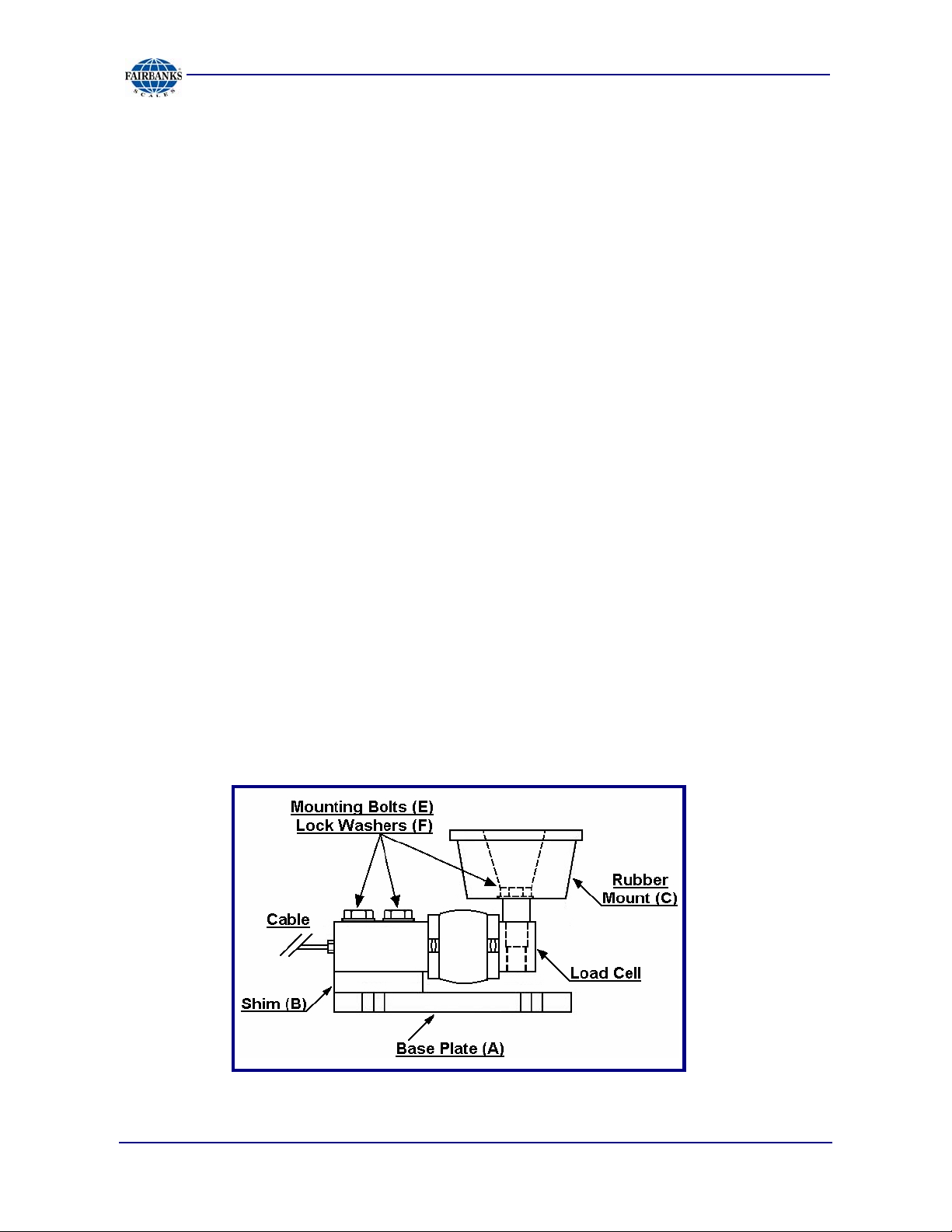
INSTALLATION
Basic Assembly Steps
Section 2: Installation
1. Raise the vessel that is to be supported by the Omnicell
®
Assemblies.
2. Secure the Assembly by safely placing blocks under the vessel to the required
height.
3. Place each Assembly onto a level surface under each support leg.
4. Set the Assemblies for the correct load cell orientation (as shown on the
following page).
5. Insert the four (4) 5/16-18 bolts, and then fasten them loosely to the support
leg for each assembly.
6. Mark the location of the anchor bolt locations.
7. Slide the assembly back and drill the anchor hole locations.
8. Re-position the load cell assemblies, level, and anchor all assemblies.
9. Lower the vessel onto the top plate of each Omnicell
®
Assembly.
10. Tighten the bolts, securing the load plates to each support leg of the vessel.
11. Remove all cribbing blocks.
12. Route the cables to the junction box and indicator.
13. Wire the Omnicell® Assemblies according to the appropriate junction box and
indicator service manual.
09/07 12 51172 Revision 1
Page 13
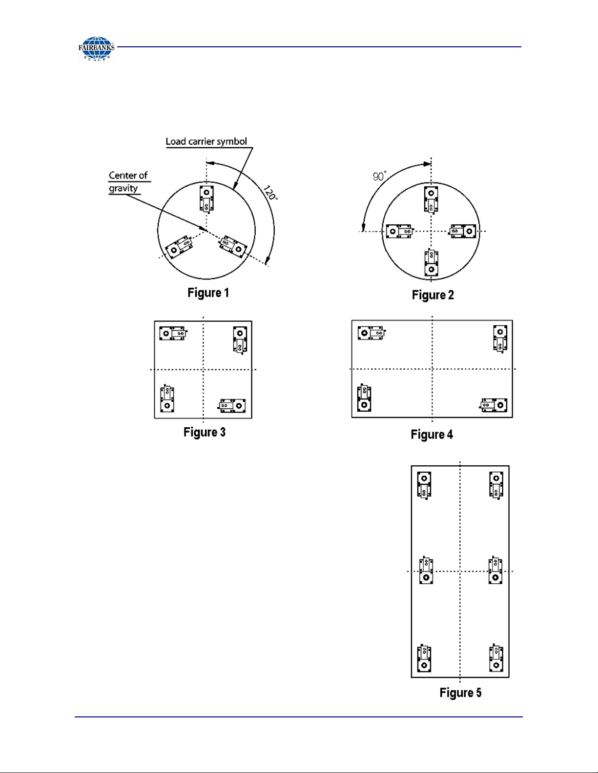
Load Cell Placement
Section 2: Installation
Follow these guidelines for installing
Omnicell
1. The loading points of the modules should be as
far from one another as the structure allows.
2. When installing the square and rectangle
Omnicell units, line up the Base Plates of the
Load Cells with each other, and align them
evenly from the end and the sides of the units.
3. When installing six Load Cells (Figure 5), be
extremely careful to position the center
Omnicells
outer Omnicells®.
09/07 13 51172 Revision 1
®
Load Cells.
®
to exactly the same height as the
Page 14
Section 3: Parts
Omnicell® 9101 FB Complete Units
Part No. Description
27871
27872
27873
27874
27875
27876
27877
27878
Each assembly includes
Omnicell, w/ Fabricated SS Mount, SS Load Cell 50 lb. Capacity
Omnicell, w/ Fabricated SS Mount, SS Load Cell 75 lb. Capacity
Omnicell, w/ Fabricated SS Mount, SS Load Cell 100 lb. Capacity
Omnicell, w/ Fabricated SS Mount, SS Load Cell 150 lb. Capacity
Omnicell, w/ Fabricated SS Mount, SS Load Cell 250 lb. Capacity
Omnicell, w/ Fabricated SS Mount, Nickel Plated Alloy Steel Load Cell, 500 lb. Capacity
Omnicell, w/ Fabricated SS Mount, Nickel Plated Alloy Steel Load Cell, 1K Capacity
Omnicell, w/ Fabricated SS Mount, Nickel Plated Alloy Steel Load Cell, 2.5K Capacity
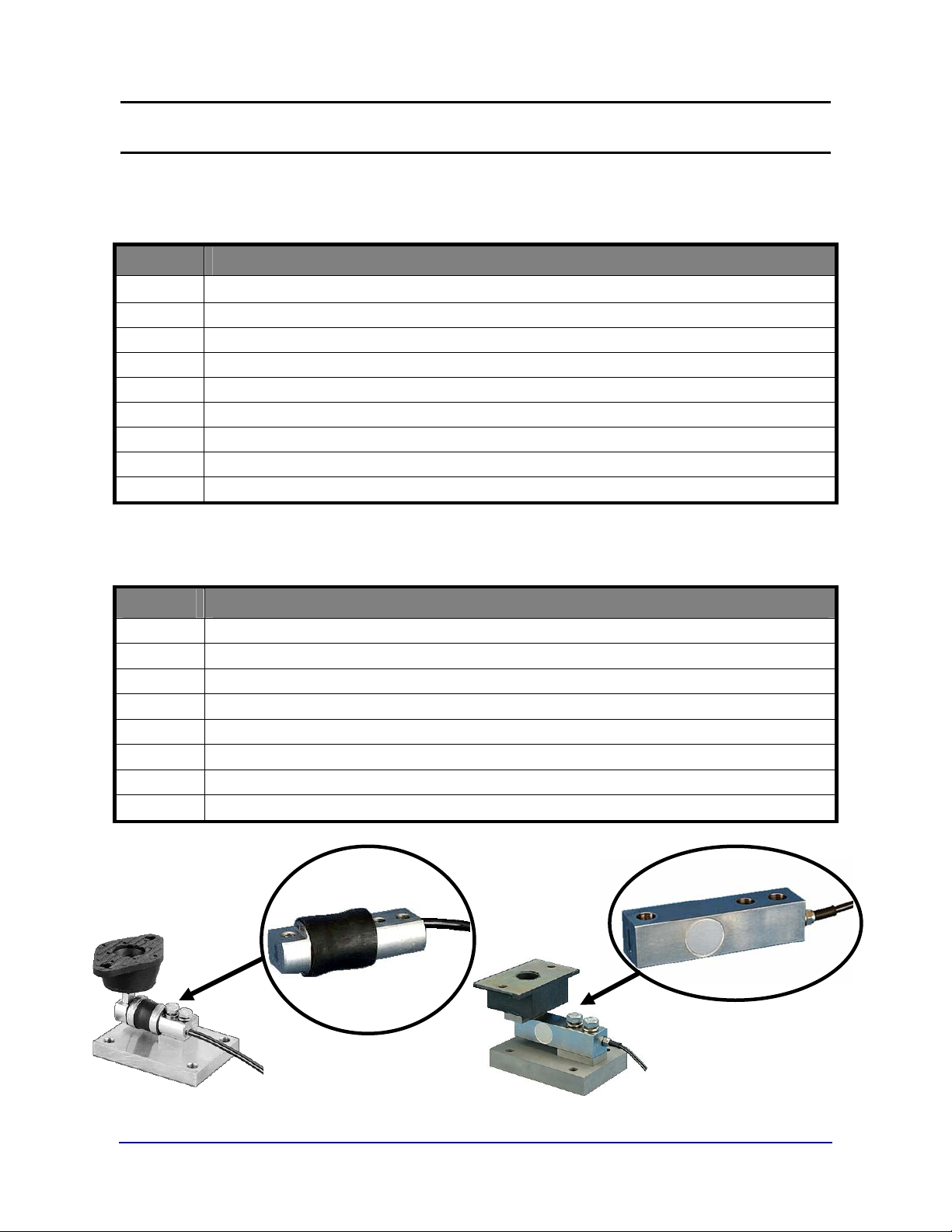
Load Cells Only
Part No. Description
27891
27892
27893
27894
27895
27896
27897
27898
Stainless Bending Beam Load Cell, 50 lb. Capacity
Stainless Bending Beam Load Cell, 75 lb. Capacity
Stainless Bending Beam Load Bell, 100 lb. Capacity
Stainless Bending Beam Load Cell, 150 lb. Capacity
Stainless Bending Beam Load Cell, 250 lb. Capacity
Alloy Steel Shear Beam Load Cell, 500 lb. Capacity
Alloy Steel Shear Beam Load Cell, 1,000 lb. Capacity
Alloy Steel Shear Beam Load Cell, 2.5000 lb. Capacity
all necessary Omnicell Unit parts.
Shear Beam Load Cell Bending Beam Load Cell
09/07 14 51172 Revision 1
Page 15

Rubber Mounts
Fairbanks
P/N
Components
Section 3: Parts
93640
93641
93642
93643
Rubber Mount 52522, 9101 FB (50 – 150 lbs)
Rubber Mount 52542, 9101 FB (250 lbs)
Rubber Mount 52172, 9101 FB (500 – 1,000 lbs)
Rubber Mount 52564-1, 9101 FB (2.500 lbs)
Parts Not Supplied with Assembly
Qty.
Per Ass’y
2
4
2
4
2
4
Components
Fastening Bolts for Vessel Attachment
5/16 - 18 UNC bolts – 50-250 lb capacity
5/16 - 18 UNC Anchors/bolts – 50-250 lb capacity
1/2 -13 UNC bolts – 500 lb capacity
7/16 - 14 UMC Anchor bolts – 500 lb capacity
3/8 - 16 UNC bolts – 1,000 & 2,500 lb capacity
7/16 - 14 UNC Anchor bolts – 1,000 & 2,500 lb capacity
09/07 15 51172 Revision 1
Page 16
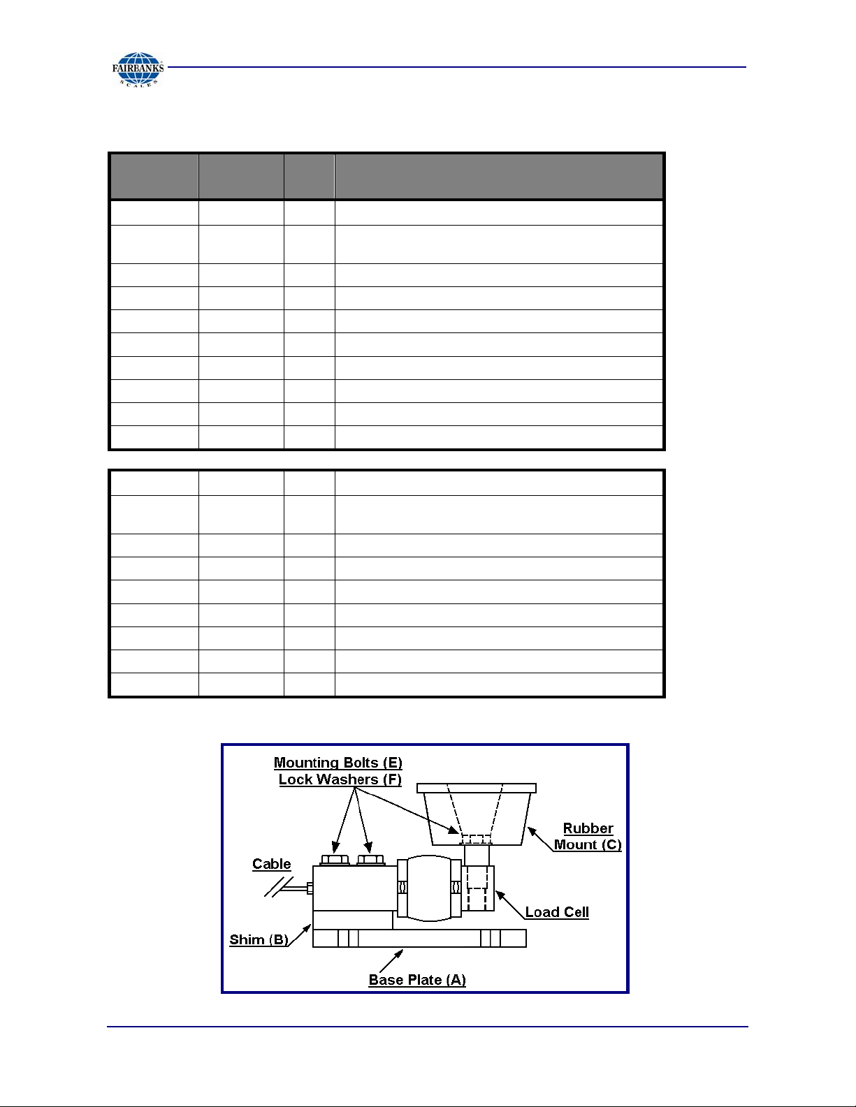
Assembly Units Without Load Cells
Section 3: Parts
Fairbanks
P/N
Diagram
Letter
Qty Components
93644 1 9101 FB Mounting Ass’y (50 - 150 lbs)
Assembly includes the following parts (without a load
cell).
1
1
1
1
1
1
2
3
SS Base Plate
Load Cell Shim Spacer
Hex Nose Spacer
Rubber Mount, 52522
Nose Bolt, 1/4-20 X .88"
Jam Nut, 3/8" - 16
Load Cell Mounting Bolt, 1/4-20 X 1.50"
Lock Washer,1/4” Spring Ring
93640
A
B
*
C
*
*
E
F
93645 1 9101 FB Mounting Ass’y (250 lbs)
Assembly includes the following parts (without a
load cell).
1
1
1
1
1
2
2
SS Base Plate
Load Cell Shim Spacer
Rubber Mount, 52542
Plain Nose Washer, 1/2 dia. X .125" Thick
Nose Bolt,1/2-20 X 2.0"
Load Cell Mounting Bolt, 1/2-13 X 2.0"
Lock Washer 1/2" Split Ring
93641
A
B
C
*
*
E
F
* Item(s) not shown on diagram.
09/07 16 51172 Revision 1
Page 17
Section 3: Parts
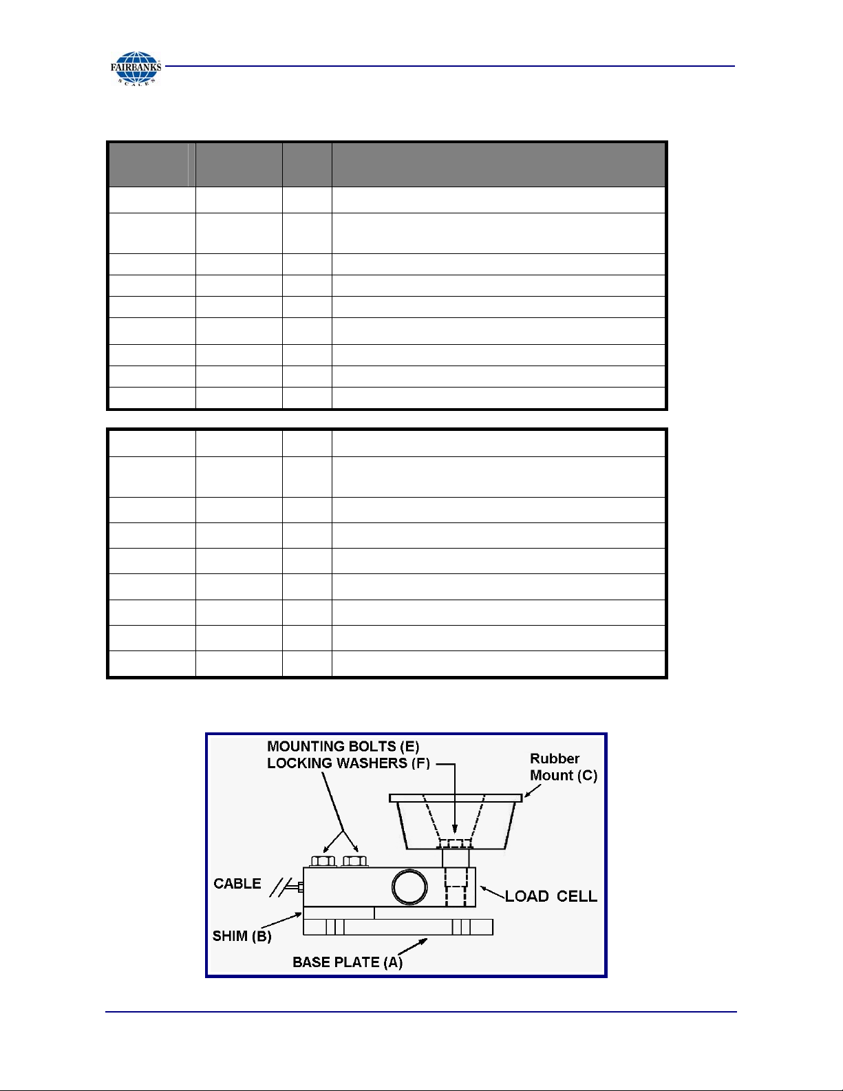
Assembly Units Without Load Cells, Continued
Fairbanks
P/N
Diagram
Letter
Qty. Components
93646 1 9101 FB Mounting Ass’y (500 & 1,000 lbs)
93642
A
B
*
C
*
E
F
Assembly includes the following parts (without a
1
1
1
1
1
2
2
load cell).
SS Base Plate
Spacer, load cell shim
Nose Spacer
Rubber Mount, 52172
Bolt, nose 1/2-20 X 2.0"
Bolt, load cell mounting 1/2-13 X 2.5"
Washer, 1/2 Split Ring, Lock
93647 1 9101 FB Mounting Ass’y (2,500 lbs)
A
B
Assembly includes the following parts (without a
load cell):
1
1
SS Base Plate
Spacer, load cell shim
93643
* Item(s) not shown on diagram.
*
C
E
E
F
1
1
1
2
2
Nose Spacer
Rubber Mount, 52564-1
Bolt, Hex Head Cap Screw, 1/2-13 X 2.5"
Bolt, Load Cell Mounting 1/2-13 X 2.5"
Washer, 1/2 Split Ring, Lock
09/07 17 51172 Revision 1
Page 18
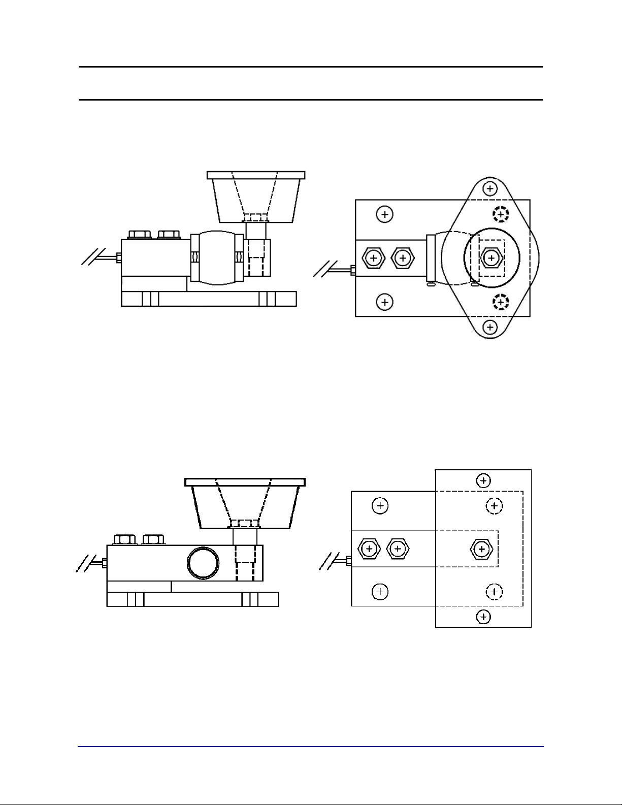
Appendix I: Omnicell Configurations
Omnicell9101 FB Bending Beam design with
capacities equal to or less than 250 pounds.
Omnicell 9101 FB Sheer Beam design with
capacities greater than 250 pounds.
09/07 18 51172 Revision 1
Page 19

Page 20

Omnicell
Manufactured by Fairbanks Scales, Inc.
821 Locust Street
Kansas City, Missouri 64106
www.fairbanks.com
Model: 9101 FB
INSTALLATION MANUAL
DOCUMENT 51172
 Loading...