


Operators Manual
FB2550 SERIES
INCLUDES:
IN/OUT APPLICATION
NETWORK APPLICATION
© 2010-2012 by Fairbanks Scales, Inc. |
51254 |
All rights reserved |
Rev. 3 07/2012 |

Amendment Record
FB2550 SERIES INSTRUMENT
DOCUMENT 51254
Manufactured by Fairbanks Scales Inc. 821 Locust
Kansas City, Missouri 64106
Created |
10/2010 |
|
Revision 1 |
05/2011 |
Released document |
Revision 2 |
04/2012 |
Updated manual to Rev. 3.x Software. Added numerous |
|
|
feature definitions and specification information. |
Revision 3 |
07/2012 |
Added Network Application information and update images. |
.

Disclaimer
Every effort has been made to provide complete and accurate information in this manual. However, although this manual may include a specifically identified warranty notice for the product, Fairbanks Scales makes no representations or warranties with respect to the contents of this manual, and reserves the right to make changes to this manual without notice when and as improvements are made.
It is the responsibility of the requesting party to develop, maintain, install, and connect networking devices and general network connectivity as it applies to the originating party’s network. No warranty or guarantee, expressed or implied, concerning the network, its design, its installation, or operational characteristics has been offered by Fairbanks Scales. Fairbanks Scales shall not be liable for any loss, damage, cost of repairs, incidental or consequential damages of any kind, whether or not based on express or implied warranty, contract, negligence, or strict liability arising in connection with the design, development, installation, or use of an intended network.
Trademarks
Award is a trademark of Award Software International, Inc.
CF and Compact Flash are trademarks of ScanDisk Corporation.
Microsoft, Microsoft Windows XP Pro, Windows XP Pro Embedded, and MS-DOS are either trademarks or registered trademarks of Microsoft Corporation.
Adobe, the Adobe logo, Acrobat, the Adobe PDF logo, Distiller, and Reader are either registered trademarks or trademarks of Adobe Systems Incorporated.
All other product names mentioned herein are used for identification purpose only and may be trademarks and/or registered trademarks of their respective companies.
© Copyright 2010-2012
This document contains proprietary information protected by copyright. All rights are reserved; no part of this manual may be reproduced, copied, translated, or transmitted in any form or by any means without prior written permission of the manufacturer.
07/2012 |
4 |
51254 Rev. 3 |

Table of Contents
SECTION 1: GENERAL INFORMATION ................................................................... |
8 |
1.1. Description................................................................................................................. |
8 |
1.2. Specifications............................................................................................................. |
9 |
SECTION 2: GETTING STARTED ........................................................................... |
11 |
2.1. Unpacking................................................................................................................ |
11 |
2.2. Equipment Location ................................................................................................. |
11 |
2.3. Safety ...................................................................................................................... |
12 |
2.4. Users’ Responsibilities............................................................................................. |
12 |
SECTION 3: OPERATIONS ..................................................................................... |
13 |
3.1. Introduction............................................................................................................... |
13 |
3.2. Key Functions .......................................................................................................... |
14 |
3.2.1. Front Panel Keypad ...................................................................................................... |
14 |
3.2.2. External Keyboard......................................................................................................... |
15 |
3.3. Proper Shutdown Procedure.................................................................................... |
16 |
3.4. Operational Procedures ........................................................................................... |
17 |
3.4.1. Basic Operations Summary ........................................................................................... |
18 |
3.5. Configuration Menu.................................................................................................. |
22 |
3.6. Operator Menu......................................................................................................... |
23 |
3.6.1. Time and Date Format .................................................................................................. |
23 |
3.6.2. Set Time and Date ........................................................................................................ |
24 |
3.6.3. Ticket Number .............................................................................................................. |
24 |
3.6.4. Load Cell Diagnostics ................................................................................................... |
26 |
3.6.5. Entering a New Tare Automatically................................................................................ |
27 |
3.6.6. Entering a New Tare using a Keyboard ......................................................................... |
27 |
3.7. Edit Customers ........................................................................................................ |
28 |
3.7.1. Adding or Editing Customers ......................................................................................... |
28 |
3.8. Editing Products....................................................................................................... |
30 |
3.8.1. Adding or Editing Products ............................................................................................ |
30 |
3.9. Product Groups........................................................................................................ |
34 |
3.9.1. Adding or Editing Product Groups ................................................................................. |
34 |
3.10. Editing Tares.......................................................................................................... |
35 |
3.10.1. Adding or Editing Tares ............................................................................................... |
36 |
3.11. Delete Incomplete Transactions............................................................................. |
38 |
3.12. Reports .................................................................................................................. |
40 |
3.12.1. Master File Reports..................................................................................................... |
40 |
3.12.2. Transaction Reports .................................................................................................... |
43 |
3.13.3. Summary Reports ....................................................................................................... |
47 |
3.12.4. Email Transaction ....................................................................................................... |
49 |
3.13. External Monitor..................................................................................................... |
50 |
3.14. Audit Trail............................................................................................................... |
51 |
3.14.1. Calibration Audit Trail .................................................................................................. |
51 |
3.14.2. Configuration Audit Trail .............................................................................................. |
51 |
07/2012 |
5 |
51254 Rev. 3 |

Table of Contents
SECTION 4: FB2550 CUSTOMIZATION ................................................................. |
52 |
4.1. Programmable Legends........................................................................................... |
52 |
4.2. Programmable Prompts ........................................................................................... |
54 |
4.3. Truck Image Type .................................................................................................... |
55 |
4.4. Entry Sequence Prompts ......................................................................................... |
56 |
SECTION 5: INPUT/ OUTPUT................................................................................. |
57 |
5.1. Introduction.............................................................................................................. |
57 |
5.2. Instrument Configuration - Printers .......................................................................... |
57 |
5.3. Printer Switch Settings............................................................................................. |
60 |
5.4. Printer Setup and Programming............................................................................... |
61 |
5.4.1. OKI ML420 Printer Settings ........................................................................................... |
61 |
5.4.2. HP P2055d Laserjet Printer Settings ............................................................................. |
65 |
5.4.3. iDP3550 Tape Printer Settings ...................................................................................... |
70 |
5.4.4. TM-U590 Ticket Printer Settings.................................................................................... |
71 |
5.4.5. TM-U295 Ticket Printer Settings.................................................................................... |
72 |
5.4.6. SP298 Printer Settings .................................................................................................. |
73 |
5.4.7. SP700 Printer Settings .................................................................................................. |
75 |
5.4.8. SP2000......................................................................................................................... |
77 |
5.4.9. SP2200......................................................................................................................... |
77 |
5.4.10. TM-U230..................................................................................................................... |
78 |
5.5. Format Tickets ......................................................................................................... |
79 |
5.6. Serial Card (30921).................................................................................................. |
83 |
5.7. Remote Display Setup and Configuration ................................................................ |
84 |
5.7.1. Serial 20mA Configuration (Multi-Function Board) ......................................................... |
84 |
5.7.2. Multi-Function Board 20 mA Wiring (J1) ........................................................................ |
86 |
5.7.3. Serial 20 mA Configuration (Serial Expansion Board) .................................................... |
87 |
5.7.4. Serial Expansion Board 20 mA Wiring (TB1) ................................................................. |
88 |
5.8 Configure Outputs..................................................................................................... |
89 |
5.8.1. Configuring an Output Data String................................................................................. |
89 |
5.8.2. Two Methods of Formatting........................................................................................... |
89 |
5.8.3. Method 1 – Pre-configured Output.......... ....................................................................... |
90 |
5.8.4. Method 2 - Customizing Output Data Strings ................................................................. |
97 |
5.9. Report Printer Configuration .................................................................................. |
105 |
5.10. IP Output Configuration........................................................................................ |
106 |
5.11. RS-485 Configuration........................................................................................... |
108 |
5.12. Network Parameters Configuration ...................................................................... |
110 |
5.13. 4-20MA Analog Card (30919)............................................................................... |
112 |
5.14. Fieldbus Protocols and Formats........................................................................... |
113 |
5.14.1. Transmission Methods ............................................................................................... |
113 |
5.14.2. Communication Format .............................................................................................. |
113 |
5.14.3. Handling Network Traffic ............................................................................................ |
113 |
5.15. Fieldbus Connections .......................................................................................... |
114 |
5.15.1. Overview of Terms ..................................................................................................... |
114 |
5.15.2. DeviceNet (30923) ..................................................................................................... |
115 |
5.15.3. ControlNet (30924)..................................................................................................... |
117 |
5.15.4. Modbus (30925) ......................................................................................................... |
119 |
5.15.5. Profibus (30922) ........................................................................................................ |
121 |
07/2012 |
6 |
51254 Rev. 3 |

Table of Contents
SECTION 6: TRAFFIC LIGHT CONTROL ............................................................ |
123 |
6.1. Traffic Light Control................................................................................................ |
123 |
6.2. Threshold Weights ................................................................................................. |
128 |
6.3. Blind Counter ......................................................................................................... |
129 |
SECTION 7: VIDEO CAMERA PROGRAMMING .................................................. |
131 |
7.1. Video Camera Setup............................................................................................... |
131 |
7.2. Installing the Camera Without Factory Defaults ..................................................... |
131 |
7.2.1. Camera Setup.............................................................................................................. |
132 |
7.2.2. Axis Network Setup...................................................................................................... |
133 |
7.2.3. Resetting to the Axis Factory Defaults .......................................................................... |
135 |
7.3. Video Camera Programming.................................................................................. |
136 |
SECTION 8: SERVICE AND MAINTENANCE ...................................................... |
139 |
8.1. Database Maintenance ........................................................................................... |
139 |
8.1.1. Database Backup......................................................................................................... |
139 |
8.1.2. Database Restore ........................................................................................................ |
145 |
8.1.3. Re-Index Database ...................................................................................................... |
149 |
8.1.4. Transaction Data Backup Days Reminder .................................................................... |
150 |
8.2. Troubleshooting – Loopback Test for Serial Ports.................................................. |
151 |
SECTION 9: NETWORK APPLICATION CONFIGURATION ................................ |
153 |
9.1. Introduction............................................................................................................ |
153 |
9.2. Standard Network Setup........................................................................................ |
153 |
9.2.1. Record Keeping ........................................................................................................... |
154 |
9.2.2. Network Connections ................................................................................................... |
155 |
9.2.3. Testing Connectivity..................................................................................................... |
155 |
9.3. Network Setup Procedure ...................................................................................... |
156 |
9.3.1. Network Terminal Name............................................................................................... |
156 |
9.3.2. Synchronizing this Terminal ......................................................................................... |
157 |
APPENDIX I: FIELDBUS INTERFACE REFERENCE DATA ................................ |
159 |
A. Introduction .............................................................................................................. |
159 |
B. Hardware Specifications........................................................................................... |
159 |
C. Software Specifications ............................................................................................ |
160 |
D. Field Bus Data Representation................................................................................. |
163 |
E. Status/Command Word Bit Usage ............................................................................ |
168 |
APPENDIX II: DATA OUTPUT ............................................................................... |
174 |
A. Remote Display Output ............................................................................................ |
174 |
B. Configure Output ...................................................................................................... |
174 |
APPENDIX III: SMA PROTOCOL .......................................................................... |
180 |
A. Standard Scale Response Message......................................................................... |
180 |
B. Examples ................................................................................................................. |
181 |
APPENDIX IV: 20MA CODES ................................................................................ |
182 |
APPENDIX V: REMOTE SWITCHES ..................................................................... |
184 |
APPENDIX VI: REMOTE SERIAL COMMUNICATION COMMANDS ................... |
185 |
07/2012 |
7 |
51254 Rev. 3 |

Section 1: General Information
1.1. DESCRIPTION
The FB2550 is a modular designed instrument, configurable and upgradable using
Printed Circuit Modules.
∙Each module provides a specific scale or I/O functionality to the weighing system.
∙The FB2550 instrument has four enclosure styles.
– Desktop – Panel Mount – Rack Mount – NEMA 4
STANDARD FEATURES
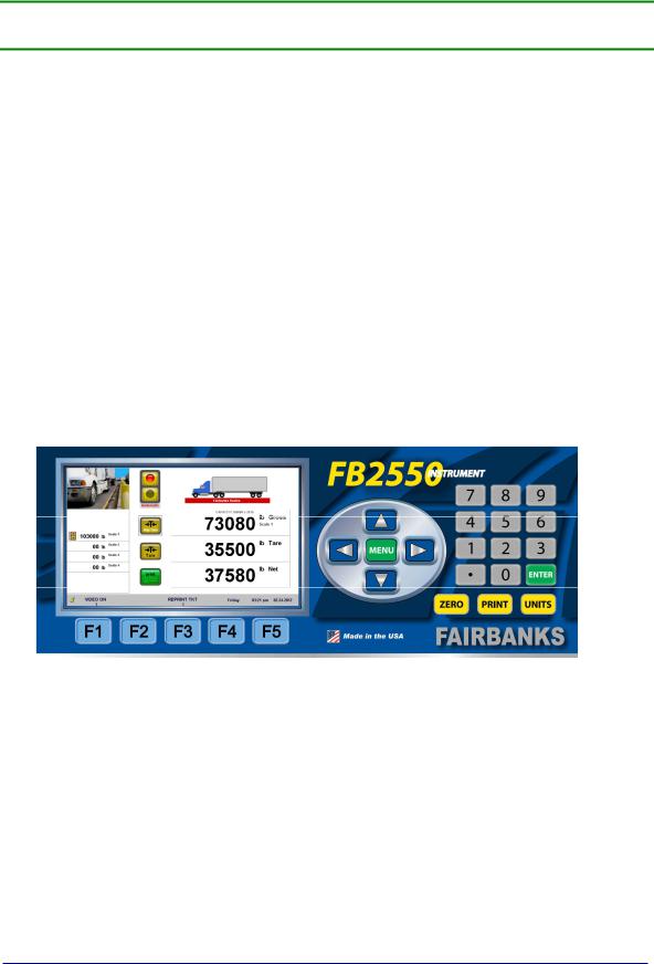
∙ |
7” full-color display |
∙ |
Multiple/ Expandable serial ports |
∙ |
Ethernet |
∙ |
Built-in reporting functions |
∙ |
SQL database |
∙ |
IP Camera interface with onscreen image |
∙ |
Touch screen operation |
∙ |
Stainless steel and aluminum desktop NEMA 12 |
∙ |
Integrated web server |
∙ |
Programmable F-key Prompts |
|
|
|
|
|
|
|
|
Figure 1 – FB2550 Block Diagram
NOTE: Any combination of eight (8) modules can be installed, restricted to this maximum number. Possibly even less, depending on the module kit type.
07/2012 |
8 |
51254 Rev. 3 |

|
|
|
|
|
|
|
|
Section 1: General Information |
|
|
1.2. SPECIFICATIONS |
|
|
|
|
|
|
|
|||
|
|
|
|
|
||||||
|
|
Enclosure |
Desktop (30770), Panel Mount (31053), Rack Mount (31173), |
|
||||||
|
|
|
|
NEMA 4 (31150) |
|
|
|
|
|
|
|
|
|
|
|
|
|
|
|
||
|
|
BIOS |
Award™ Software |
|
|
|
|
|
||
|
|
RAM |
1 GB |
|
|
|
|
|
|
|
|
|
|
|
|
|
|
|
|
|
|
|
|
Disk Storage |
8 GB |
|
|
|
|
|
|
|
|
|
Operating System |
Windows XP Professional Embedded |
|
|
|
||||
|
|
|
|
|
||||||
|
|
Serial Outputs |
Up to 12 serial ports and 4 built-in USB ports. The USB port on the |
|
||||||
|
|
|
|
Multi-Function board is dedicated for a keyboard only. |
|
|||||
|
|
Digital I/O |
Up to 28 I/O |
|
|
|
|
|
||
|
|
|
|
|
||||||
|
|
Ethernet Interface |
PCI 10/100 Mbps Ethernet Complies with IEEE 802.3x Standards |
|
||||||
|
|
Display |
7” Diagonal Touch Screen LCD Color |
|
|
|
||||
|
|
|
|
|
|
|
|
|||
|
|
Scale Interface Options |
• Intalogix Technology |
|
|
|
|
|||
|
|
|
|
─ Intalogix Power Supply and Communications (30916) |
|
|||||
|
|
|
|
─ Scale Interface Controller (30918) |
|
|
|
|||
|
|
|
|
─ External QMB Interface (30433) |
|
|
|
|||
|
|
|
|
─ External Intalogix Communication Board (28330) |
|
|||||
|
|
|
|
|
Maximum of twenty (20) 1000 Ω or twelve (12) 350 Ω |
|
||||
|
|
|
|
|
cells |
|
|
|
|
|
|
|
|
|
─ External Dual Intalogix Communication Board (28333). |
|
|||||
|
|
|
|
|
Up to forty (40) 1000 Ω or twenty-four (24) 350 Ω cells. |
|
||||
|
|
|
|
• Analog Technology. |
|
|
|
|
|
|
|
|
|
|
─ A/D Convertor Load Cell Interface (31079) |
|
|||||
|
|
|
|
|
Up to sixteen (16) 1000 Ω or eight (8) 350 Ω cells. |
|
||||
|
|
|
|
─ External Analog Load Cell Interface (29646). |
|
|||||
|
|
|
|
|
Up to sixteen (16) 1000 Ω or ten (10) 350 Ω cells. |
|
||||
|
|
|
|
─ External Dual Analog Load Cell Interface (30124). |
|
|||||
|
|
|
|
|
Up to sixteen (16 x 2 = 32) 1000 Ω, or ten (10 X 2 = 20) |
|
||||
|
|
|
|
|
350 Ω cells. |
|
|
|
|
|
|
|
|
|
|
Maximum of two (2) per FB2550. |
|
||||
|
|
Accessories |
• Serial Interface (30921), including: |
|
|
|
||||
|
|
|
|
– |
RS232 |
– |
RS-485 |
– 20mA |
|
|
|
|
|
|
• 4-20mA (30919) |
|
|
|
|
|
|
|
|
|
|
• Mini keyboard (25498) |
|
|
|
|
||
|
|
|
|
─ USB – 87 key |
|
|
|
|
|
|
|
|
|
|
• Keyboard (31036) |
|
|
|
|
|
|
|
|
|
|
─ USB – 104 key |
|
|
|
|
|
|
|
|
|
|
• SVP/ Uninterruptible Power Supply (UPS) (15892) |
|
|||||
|
|
|
|
─ 500 VA Rating |
|
|
|
|
|
|
|
|
|
|
• Field Bus Gateway |
|
|
|
|
|
|
|
|
|
|
– |
ProfiBus (30922) |
|
– |
DeviceNet (30923) |
|
|
|
|
|
|
– |
ControlNet (30924) |
|
– |
ModBus (30925) |
|
|
|
|
|
|
|
|
|
|
|
||
|
|
|
|
|
|
|
|
|
|
|
07/2012 |
|
|
9 |
|
|
51254 Rev. 3 |
|
|||

Section 1: General Information
1.2. SPECIFICATIONS, CONTINUED
Power Requirements |
100 - 130 VAC @ 12A @ 60 Hz +/- 2 Hz |
|
|
|
– Separate and dedicated circuit. |
|
|
– Neutral to Ground voltage should be < 0.2 VAC |
|
|
– One Amp (1A) is typical. Twelve Amps (12A) is a fully equipped |
|
|
model. |
|
|
|
ETL Listed |
∙ Conforms to UL STD 60950-1. |
|
|
∙ CAN/CSA C 22.2 NO.60950-1-03. |
|
Approvals |
∙ |
CC# 10-089 |
|
∙ |
MC# AM-5805 |
|
|
|
07/2012 |
10 |
51254 Rev. 3 |
Section 2: Getting Started
2.1. UNPACKING
Follow these guidelines when unpacking all equipment:
Check in all components and accessories according to the customer's order.
Remove all components from their packing material, checking against the invoice that they are accounted for and not damaged.
∙Advise the shipper immediately, if damage has occurred.
∙Order any parts necessary to replace those which have been damaged.
∙Keep the shipping container and packing material for future use.
∙Check the packing list.
Collect all necessary installation manuals for the equipment and accessories.
Open the equipment and perform an inspection, making certain that all hardware, electrical connections, and printed circuit assemblies are secure.
Do not reinstall the cover if the final installation is to be performed after the pre-installation checkout.
2.2.EQUIPMENT LOCATION
Position the equipment with these points in mind:
Intense direct sunlight can harm the display.
Airborne particles can activate the touch screen.
Work areas should be relatively free from drafts and vibrations.
Do not locate near magnetic material or equipment/instruments which use magnets in their design.
Avoid areas which have extreme variations in room temperatures. Temperatures outside the instrument’s specifications will affect the weighing accuracy of this product.
07/2012 |
11 |
51254 Rev. 3 |

Section 2: Getting Started
2.3. SAFETY
Follow these safety precautions during operation:
Properly shut down the equipment and remove power before any cables or hardware is disconnected.
Unplug the power cord to the equipment after a proper shut down before servicing the equipment.
2.4.USERS’ RESPONSIBILITIES
All electronic and mechanical calibrations and/or adjustments required for making this equipment perform to accuracy and operational specifications should be performed by trained service personnel.
Absolutely no physical, electrical or program modifications other than selection of standard options and accessories are to be made to this equipment.
─Electrical connections other than those specified may not be performed, and physical alterations (holes, etc.) are not allowed.
The equipment consists of printed circuit assemblies which must be handled using ESD handling procedures, and must be replaced as units.
─Replacement of individual components is not allowed.
07/2012 |
12 |
51254 Rev. 3 |
Section 3: Operations
3.1. INTRODUCTION
Listed below are the options available for weighing.
∙Gross Weighing Only
∙Gross-Tare-Net Weighing
∙Gross Weighing or Gross-Tare-Net Weighing
∙Inbound / Outbound Weighing
∙Inbound / Outbound Weighing or Gross Weighing Only
∙Inbound / Outbound Weighing or Gross-Tare-Net Weighing.
∙Inbound / Outbound Weighing or Gross Weighing or Gross-Tare-Net Weighing.
07/2012 |
13 |
51254 Rev. 3 |

Section 3: Operations
3.2.KEY FUNCTIONS
3.2.1.FRONT PANEL KEYPAD
Key(s) |
Function |
|
0-9 |
Used to enter numeric data such as tares and IDs. |
|
|
|
|
F1 |
Video On/ Video Off. This key will turn the camera image on or off if |
|
|
cameras are enabled. |
|
|
|
|
F2 |
Expand image. This will enlarge the camera image to a full display image. |
|
|
Pressing it again will return the image to its normal size. |
|
|
|
|
F3 |
Reprint Ticket. This key will permit the reprinting of a previously printed |
|
|
ticket. This key will also function to pull up a list of items such as Loop, |
|
|
Customer, or Product during the weighing process. |
|
|
|
|
F4 |
Void ticket(s). Available at the Initial Weigh Screen when scale is at Zero. |
|
|
|
|
F5 |
Power Off. This key turns the instrument off. The power cord must be |
|
|
unplugged and plugged back in to power up the instrument. This key, while |
|
|
in the configuration menu, performs a backup to the previous screen. |
|
|
|
|
Enter |
Will store or accept a data entry item. |
|
|
|
|
Zero |
Will Zero the scale |
|
|
|
|
Units |
Will toggle the Units |
|
|
|
|
Will initiate a print cycle. |
||
|
|
|
Menu |
Will open the Menu for the Configuration Home |
|
|
|
|
Up Arrow |
Navigate up. |
|
|
|
|
Down Arrow |
Navigate down. |
|
|
|
|
Left Arrow |
Navigate left. |
|
|
|
|
Right Arrow |
Navigate right. |
|
|
|
07/2012 |
14 |
51254 Rev. 3 |

Section 3: Operations
3.2.KEY FUNCTIONS, CONTINUED
3.2.2.EXTERNAL KEYBOARD
Key(s) |
Function |
|
F1 |
Video On/ Video Off. This key will turn the camera image on or off if |
|
|
cameras are enabled. |
|
|
|
|
F2 |
Expand image. This will enlarge the camera image to a full display image. |
|
|
Pressing it again will return the image to its normal size. |
|
|
|
|
F3 |
Reprint Ticket. This key will permit the reprinting of a previously printed |
|
|
ticket. This key will also function to pull up a list of items such as Loop, |
|
|
Customer, or Product during the weighing process. |
|
|
|
|
F4 |
Void ticket(s). Available at the Initial Weigh Screen when scale is at Zero. |
|
|
|
|
F5 |
Power Off. This key turns the instrument off. The power cord must be |
|
|
unplugged and plugged back in to power up the instrument. This key, while |
|
|
in the configuration menu, performs a backup to the previous screen. |
|
|
|
|
Pause Break |
Will Zero the scale |
|
|
|
|
Scroll Lock |
Will toggle the Units |
|
|
|
|
PrtSc SysRq |
Will initiate a print cycle. |
|
|
|
|
Home |
Will open the Menu for the Configuration Home |
|
|
|
|
ESC |
Clear or restart, shrink or expand image |
|
|
|
|
Ctrl + Shift + H |
System Information |
|
|
|
|
Alphanumeric keys |
Used to enter various data. i.e. – truck id’s, products |
|
|
|
07/2012 |
15 |
51254 Rev. 3 |
Section 3: Operations
3.3. PROPER SHUTDOWN PROCEDURE
C A U T I O N
FB2550 must be shut down properly!
Failure to shut down properly can result in corrupting essential software files necessary for proper operation, and may require replacement of the 8GB Flash Drive.
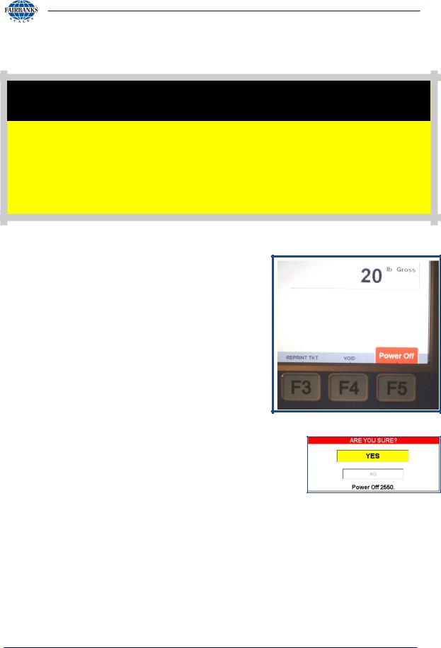
The FB2550 Instrument is best shut down when there is no weight on the scale. The instrument can also be shut down when there is weight on the scale.
∙When there is no weight on the scale, the POWER OFF (F5) notification displays.
–There is no shut off notification for this.
∙Whenever there is weight on the scale, the F5 button is still active, but hidden.
–A Shut Off Warning appears whenever F5 is pushed and there is weight on the scale.
∙The POWER OFF (F5) is inactive when any Service Programming is being completed.
1.Press the F5 key to begin the shut-down process.
2.After proper shut-down is complete, ALWAYS unplug the
Instrument from AC power.
–Until the FB2550 is unplugged from AC power, it will continue to supply operating voltage to the instrument circuits.
07/2012 |
16 |
51254 Rev. 3 |

Section 3: Operations
3.3. PROPER SHUTDOWN PROCEDURE, CONTINUED
A T T E N T I O N !
After proper shut-down is complete, ALWAYS unplug the Instrument from AC power.
Until the FB2550 is unplugged from AC power, the Instrument is still powered.
W A R N I N G !
DO NOT CONNECT OR DISCONNECT WIRING FROM SCALE COMPONENTS WHILE THE FB2550 IS ENERGIZED.
FAIRBANKS SCALES
STRONGLY RECOMMENDS USING A SUITABLY SIZED UPS.
SVP/ Uninterruptible Power Supply (UPS) (15892), 500 VA Rating
07/2012 |
17 |
51254 Rev. 3 |

Section 3: Operations
3.4. OPERATIONAL PROCEDURES
3.4.1. BASIC OPERATIONS SUMMARY
GROSS WEIGHING
1.Press the ZERO key.
2.Drive the vehicle to be weighed on the platform.
3.Once the display stabilizes, press the
PRINT key.
– A Gross Weight ticket prints.
GROSS-TARE-NET WEIGHING
1.Press the ZERO key.
2.Drive the vehicle to be weighed on the platform.
a.Press either the KEY TARE or TARE button.
b.If KEY TARE is selected, enter the known Tare Weight on the keypad.
c.If TARE is selected, the weight on the display is captured as a Tare Weight.
3.Load the vehicle with product.
4.Press the PRINT key and a Gross-Tare-Net Ticket will be printed.
–Mode Change – When a KEY TARE or TARE button is pressed, the scale automatically switches from the Gross Weighing Mode to the Gross-Tare- Net Mode.
5.To change the scale from the Gross-Tare-Net Mode back to the Gross Weighing Mode, press KEY TARE and enter a zero (0) from the keypad.
NOTE: If the display shows cell(s) failure, this indicates an error on the platform.
Check the platform for equipment, debris, or other materials and remove them. If this does not resolve the condition, call for service.
07/2012 |
18 |
51254 Rev. 3 |

Section 3: Operations
3.4.1. BASIC OPERATIONS SUMMARY, CONTINUED
INBOUND/OUTBOUND WEIGHING
The INBOUND/OUTBOUND Mode follows these steps.
1.With the indicator powered up, press the ZERO key.
2.Drive the vehicle onto the platform, whether it is either full or empty.
3.Press the INBOUND key.
–The Indicator displays the LOOP ID NUMBER on the screen, then also prints it on the Transaction Ticket.
4.Drive off the scale and process the trailer, by either filling up or emptying it.
5.The same vehicle returns to the scale, either full or empty.
6.Press the OUTBOUND button.
7a. If it is known, enter the LOOP ID Number with the keypad, then press
ENTER.
OR
7b. If the Loop ID Number is not known, press the F3 key to open the full
INBOUND LIST.
–The Inbound, Outbound and the Tare weighment amounts together make a COMPLETE TRANSACTION. Weighment of the empty vehicle is the STORED TARE. An Inbound Weighment without an Outboud Weighment is an INCOMPLETE TRANSACTION.
–The list of Incomplete Transactions displays. 7. Select the correct LOOP ID number.
07/2012 |
19 |
51254 Rev. 3 |

Section 3: Operations
3.4.1. BASIC OPERATIONS SUMMARY, CONTINUED
If any input fields are empty, information can be added from this window.
–An external keyboard is necessary to edit these windows.
9.Place the cursor in the empty field, then while in either the Customer or Product field, press ENTER on the keyboard.
If a window box appears, indicating the value entered does not currently exist follow steps 10-14 otherwise select ENTER to accept your entry.
10.To add it, select YES.
11.Input the SUPERVISOR or
Service PASSWORD when prompted.
12.Click the EDIT button to change Customer or Product input fields.
13.Input the correct information in fields.
14.Press the ENTER key.
07/2012 |
20 |
51254 Rev. 3 |
Section 3: Operations
3.4.1. BASIC OPERATIONS SUMMARY, CONTINUED
15.A pop-up message asks “Do you want to Add it?” [In the Instrument database].
16.Click the YES button, and the editing window displays.
NOTE: See 3.7. EDITING CUSTOMERS thru 3.8. EDITING PRODUCTS for complete details about how to set these up.
17.Enter or edit any of the current information within these fields.
18.Click the SAVE button
∙Select BACK: EXIT to return to the Weight Window.
19.Proceed with weighing
07/2012 |
21 |
51254 Rev. 3 |
Section 3: Operations
3.5. CONFIGURATION MENU
The FFB2550 Instrument Program provides an intuitive means for configuration and programming.
Remote configuration of the instrument using a Network interface is also possible.
There are three levels of access: Standard Users, Supervisors, and Service Technicians.
–No LOGIN is required for standard Scale Operators.
–Supervisors and Service personnel must LOGIN to gain access to the
CONFIGURATION menu.
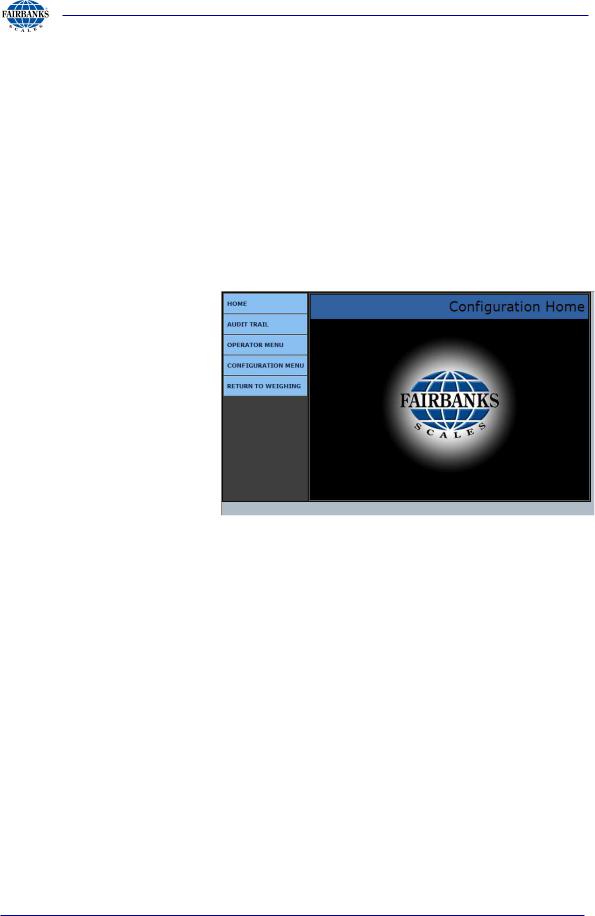
|
HOME |
Returns the operator to the Configuration Home page |
|
|
AUDIT TRAIL |
|
Identifies how many times and when changes have |
|
|
been made to the scale’s Calibration or Configuration |
|
|
|
|
settings. |
|
|
|
|
|
OPERATOR MENU |
|
User access for Time/Date, Ticket Number, Load Cell |
|
|
Diagnostics, and Keyboard Tare entries. |
|
|
|
|
|
|
CONFIGURATION MENU |
|
Supervisor access to communications programming and |
|
|
||
|
|
functions, ticket formats, programmable legends and |
|
|
|
|
prompts, camera inputs and weight threshold. |
|
RETURN TO WEIGHING |
|
Returns the user to the Weighing Display Screen. |
|
|
|
|
07/2012 |
22 |
51254 Rev. 3 |

Section 3: Operations
3.6. OPERATOR MENU
The OPERATOR MENU allows basic operations of the instrument.
–Allows access to change the time, date, ticket number, and the formatting of the time and date.
–Allows basic diagnostics of the load cells in the scale(s), with beneficial information for scale operations.
Selecting BACK: HOME returns to the Configuration Home Menu.
3.6.1. TIME AND DATE FORMAT
1.Select TIME FORMAT from the choices noted below.
∙ |
H:M |
∙ |
H:M:S |
∙ |
HH:MM |
∙ |
HH:MM:SS |
2.Open the AM/PM option, which permits 12 hour or 24 hour format.
3.Touch the DATE FORMAT, and then select best one for the company’s needs.
4.Select one available DATE
SEPERATOR formats include(SPACE), /, and –.
5.Press the SAVE CHANGES button when any changes are made, or they will be lost.
∙Select BACK: OPERATOR MENU to return to the Operator Menu.
07/2012 |
23 |
51254 Rev. 3 |
Section 3: Operations
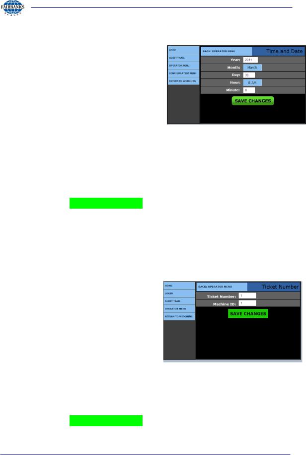
3.6.2. SET TIME AND DATE
1.Enter the YEAR option by typing the correct year into the box next to the legend.
2.Enter the MONTH option by typing the correct year into the box next to the legend.
3.Enter the DAY option by typing the correct year into the box next to the legend.
4.Enter the HOUR option by typing the correct year into the box next to the legend.
5.Enter the MINUTE option by typing the correct year into the box next to the legend.
6.Press the SAVE CHANGES button when any changes are made, or they will be lost.
∙Select BACK: OPERATOR MENU to return to the Operator Menu.
3.6.3. TICKET NUMBER
1.Enter the TICKET NUMBER by typing the correct value into the box next to the legend.
–Allows a maximum entry of six (6) digits.
2.Enter the MACHINE ID by typing the correct value into the box next to the legend.
–This value is used for customer identification purposes if required.
Default = 1
3.Press the SAVE CHANGES button when any changes are made, or they will be lost.
07/2012 |
24 |
51254 Rev. 3 |

Section 3: Operations
∙Select BACK: OPERATOR MENU to return to the Operator Menu.
07/2012 |
25 |
51254 Rev. 3 |
Section 3: Operations
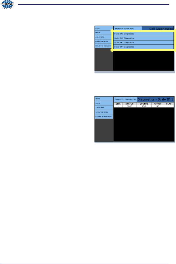
3.6.4. LOAD CELL DIAGNOSTICS
Instruments equipped with Intalogix® technology have load cell diagnostics features for easier troubleshooting capabilities.
1.To view the diagnostic information, select the correct scale.
∙Select BACK: OPERATOR MENU to return to the Operator Menu.
A. Scale ID x Diagnostics
The diagnostic screen gives a quick snapshot of how each load cell is performing.
– CELL: Identifies the load cell in the scale platform.
– STATUS: Compares the load cell output to stored calibration values and posts a GOOD or BAD condition.
– COUNTS: Displays the load cell’s current counts.
– GHOST: Ability to electronically “mimic” or duplicate a l oad cell if equipped with an Intalogix™ Interface for load cell communications (preventing system failure and/or shutdown).
– FLAG: Visual flags “ * ” are used to identify problem load cell(s) on diagnostic screen until flag is manually cleared This improves the ability to identify intermittent issues.
∙Select BACK: CELL DIAGNOSTICS to return to the Cell Diagnostics Menu.
07/2012 |
26 |
51254 Rev. 3 |

Section 3: Operations
3.6.5. ENTERING A NEW TARE AUTOMATICALLY
1.Enter the TARE ID numeric value to store and recall a tare weight saved.
–The Tare Weight value is either what is currently on the scale, or was entered previously.
–This value cannot be edited.
2.Select the correct UNITS value.
∙A Tare Date generates automatically when the Tare is entered.
∙The Manual Tare option is not used in this programming menu.
3.Enter the VEHICLE
DESCRIPTION.
–This is a unique description or label for the tare weight, and how it is associated.
3.6.6. ENTERING A NEW TARE USING A KEYBOARD
1.Enter a new TARE ID numeric value to save and recall the tare Weight.
2. Enter the TARE WEIGHT manually using the keyboard.
3.Select the UNITS for the new Tare.
–The Tare Date records the date and time the tare generates automatically.
–The Manual Tare is a flag designating the tare is manually entered.
4.Enter the VEHICLE DESCRIPTION.
–This is a unique description or label for the tare weight, and how it is associated.
5.Press the SAVE CHANGES button when any changes are made, or they will be lost.
∙Select BACK: OPERATOR MENU to return to the Operator Menu.
07/2012 |
27 |
51254 Rev. 3 |
Section 3: Operations
3.7. EDIT CUSTOMERS
The FB2550 Instrument stores customer’s name and address, as well as information used for reporting accumulated weights.
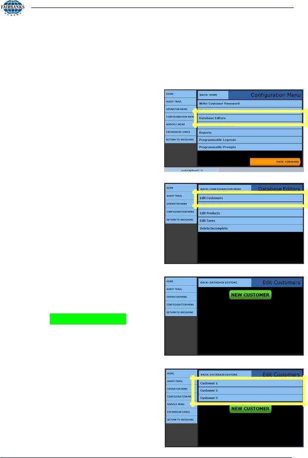
3.7.1. ADDING OR EDITING CUSTOMERS
1.Select LOGIN.
2.Enter the Supervisor Password or Service Password.
3.Select the CONFIGURATION
MENU
4. Press DATABASE EDITORS.
5. Select EDIT CUSTOMERS.
The first time a customer will be entered, the screen will appear as shown.
6a. Press the NEW CUSTOMER button.
OR…
6b. Select the existing customer record which needs editing or updating.
07/2012 |
28 |
51254 Rev. 3 |

Section 3: Operations
3.7.1. ADDING OR EDITING CUSTOMERS, CONTINUED
7.Enter the unique customer number in the CUSTOMER ID data entry box.
–When selecting a preexisting Customer, the Customer ID will generate automatically.
∙The TOTAL data entry box is automatically populated and updated at every weighment that uses the Customer ID Value.
–This provides a running total of Net weight for each customer.
8.Input any pertinent company information in the ADDRESS 1 THRU 4 data entry boxes.
–Include customer names, addresses, telephone numbers, fax numbers, and point-of-contact names.
∙Press the SAVE CHANGES button when any changes are made, or they will be lost. Select BACK: DATABASE EDITORS to return to the Database
Editors menu.
OR
∙Select BACK: EDIT CUSTOMERS to return to the the Edit Customers menu.
07/2012 |
29 |
51254 Rev. 3 |

Section 3: Operations
3.8. EDITING PRODUCTS
The FB2550 Instrument can store a great deal of information about products.
The product id, conversion factor, conversion factor units, and number of decimal places are entered as information used for reporting such as accumulated weights.
This menu adds new product or edits existing product.
A Supervisor or Service level access is required to add or edit the products.
3.8.1. ADDING OR EDITING PRODUCTS
1.Select LOGIN.
2.Enter the Supervisor Password or Service Password.
3.Select the CONFIGURATION
MENU.
4.Click on the DATABASE EDITORS button.
5. Select EDIT PRODUCTS.
07/2012 |
30 |
51254 Rev. 3 |
 Loading...