


OPERATION MANUAL
X Series
Process Indicator
PR 5410
© 2008 by Fairbanks Scales, Inc. All rights reserved
51207
Revision 1 |
10/08 |

Disclaimer
Every effort has been made to provide complete and accurate information in this manual. However, although this manual may include a specifically identified warranty notice for the product, Fairbanks Scales makes no representations or warranties with respect to the contents of this manual, and reserves the right to make changes to this manual without notice when and as improvements are made.
Fairbanks Scales shall not be liable for any loss, damage, cost of repairs, incidental or consequential damages of any kind, whether or not based on express or implied warranty, contract, negligence, or strict liability arising in connection with the design, development, installation, or use of the scale.
© Copyright 2008
This document contains proprietary information protected by copyright. All rights are reserved; no part of this manual may be reproduced, copied, translated or transmitted in any form or by any means without prior written permission of the manufacturer.
10/08 |
2 |
51207 Revision 1 |

|
|
|
|
Table of Contents |
|
|
|
||
Table of Contents |
|
|||
1 Warnings and Safety Precautions............................................................................. |
10 |
|||
1.1 |
INTENDED USE ......................................................................................................................... |
|
10 |
|
1.2 |
INITIAL INSPECTION .................................................................................................................. |
10 |
||
1.3 |
BEFORE COMMISSIONING ......................................................................................................... |
10 |
||
1.3.1 |
Installation |
|
10 |
|
1.3.2 |
Opening the Instrument |
10 |
||
1.3.3 |
Grounding and Shock Prevention PR 5410/00 |
11 |
||
1.3.4 |
Grounding and Shock Prevention PR 5410/01 |
11 |
||
1.3.5 |
Power Connection and Power Supply PR 5410/00 |
11 |
||
1.3.6 |
Power Connection 24 VDC PR5410/01 |
11 |
||
1.3.7 |
Failure and Excessive Stress |
11 |
||
1.3.8 |
Important Note |
11 |
||
2 Process Indicator ....................................................................................................... |
12 |
|||
2.1 |
OVERVIEW OF THE INSTRUMENT................................................................................................ |
12 |
||
2.2 |
HOUSING.................................................................................................................................. |
|
13 |
|
2.3 |
DISPLAY AND CONTROLS .......................................................................................................... |
14 |
||
2.3.1 |
Display |
|
14 |
|
2.3.2 |
Front-Panel Keys |
14 |
||
2.3.3 |
Selection Using the Navigation Keys (VNC) |
15 |
||
2.3.4 |
Tool Tip (VNC) |
15 |
||
2.3.5 |
System Messages during Input (VNC) |
16 |
||
2.3.6 |
Overview of Accessories |
17 |
||
2.3.7 |
Plug-in Cards |
18 |
||
3 Installing the Instrument and Plug-in Cards ............................................................ |
19 |
|||
3.1 |
MECHANICAL PREPARATION ..................................................................................................... |
19 |
||
3.2 |
HARDWARE CONSTRUCTION ..................................................................................................... |
19 |
||
3.3 |
MAIN BOARD ............................................................................................................................ |
|
19 |
|
3.3.1 |
Network Port |
|
20 |
|
3.3.2 |
Standard RS-232 Interface |
20 |
||
3.3.3 |
Optocoupler Inputs |
22 |
||
3.3.4 |
Optocoupler Outputs |
23 |
||
3.4 |
ACCESSORIES .......................................................................................................................... |
|
24 |
|
3.4.1 |
Installing Plug-in Cards |
24 |
||
3.4.2 |
Cable Connection in the D-Sub Connector Mating Plug |
25 |
||
3.4.3 |
PR 5510/02 |
Serial I/O |
26 |
|
3.4.4 |
PR 5510/04 |
Serial I/O |
27 |
|
3.4.5 |
PR 5510/07 Analog Input/Output Card |
31 |
||
3.4.6 |
PR 5510/08 BCD Output (Open Emitter) |
33 |
||
3.4.7 |
PR 5510/09 BCD Output (Open Collector) |
36 |
||
3.4.8 |
PR 5510/12 |
6 Optocoupler Inputs / 12 Optocoupler Outputs |
41 |
|
3.4.9 |
PR 1721/31 |
Profibus Interface |
46 |
|
3.4.10 |
PR 1721/32 |
Interbus Interface |
47 |
|
3.4.11 |
PR 1721/34 |
DeviceNet Interface |
48 |
|
3.4.12 |
PR 1721/37 EtherNet/IP Schnittstelle |
49 |
||
3.4.13 |
PR 5510/14 ModBus TCP Interface |
51 |
||
3.5 |
CONNECTING LOAD CELLS ....................................................................................................... |
52 |
||
3.5.1 |
Connecting a Load Cell with 4-Wire Cable |
52 |
||
3.5.2 |
Connecting PR 6221 Load Cells |
52 |
||
10/08 |
4 |
51207 Revision 1 |

|
|
|
Table of Contents |
|
|
|
|
3.5 |
CONNECTING LOAD CELLS, CONTINUED |
|
|
3.5.3 |
Connecting up to 8 Load Cells (650 Ohms) Using 6-Wire Connecting Cable |
53 |
|
3.5.4 |
Connecting Load Cells with External Supply |
54 |
|
3.5.5 |
Connecting Load Cells via Intrinsically Safe Load Cell Interface PR 1626/60 |
55 |
|
3.5.6 |
Connecting Platforms (CAP...) |
56 |
|
4 Commissioning ........................................................................................................... |
57 |
||
4.1 |
DATA PROTECTION/POWER FAILURE ........................................................................................ |
57 |
|
4.1.1 |
CAL Switch |
57 |
|
4.2 SWITCHING ON THE INSTRUMENT .............................................................................................. |
58 |
||
4.2.1 |
Display Test |
58 |
|
4.2.2 |
Front-Panel Key Test |
58 |
|
4.2.3 |
Resetting the Instrument to the Factory Settings |
58 |
|
4.2.4 |
Setting the Network Address Using Front-Panel Keys |
59 |
|
4.2.5 |
Viewing the Network Address via Front-Panel Keys |
59 |
|
4.2.6 |
Searching the Instrument in the Network Using 'IndicatorBrowser' |
59 |
|
4.2.7 |
Loading New Software |
60 |
|
4.3 CONFIGURATION AND CALIBRATION USING FRONT KEYS ........................................................... |
61 |
||
4.3.1 |
Meaning of Front Keys |
61 |
|
4.3.2 |
Entering Date and Time |
61 |
|
4.3.3 |
Parameter Table |
62 |
|
4.3.4 |
New Calibration using Front Keys |
64 |
|
4.3.5 |
Subsequent Change of Deadload using Front Keys |
65 |
|
4.3.6 |
View Calibration Data |
65 |
|
4.3.7 |
View Calibration Data for Deadload and Maximum Load |
66 |
|
4.3.8 |
PIN Code |
66 |
|
4.4 OPERATION USING A PC .......................................................................................................... |
67 |
||
4.4.1 |
Operation Using the VNC Program |
67 |
|
4.4.2 |
Operation Using Internet Browser |
68 |
|
4.4.3 |
INFO Function |
69 |
|
4.4.4 |
Setup Function (VNC) |
70 |
|
4.4.5 |
Setup Menu (VNC): Overview |
70 |
|
4.4.6 |
Calibration Menu |
71 |
|
4.5 |
CALIBRATION ........................................................................................................................... |
72 |
|
4.5.1 |
Displaying Calibration Data |
72 |
|
4.5.2 |
Selecting the Calibration Mode |
73 |
|
4.5.3 |
Determining the Maximum Capacity (Max) |
74 |
|
4.5.4 |
Determining the Scale Interval |
75 |
|
4.5.5 |
Determining the Dead Load |
75 |
|
4.5.6 |
Calibration with Weight (by Load) |
76 |
|
4.5.7 |
Calibration with mV/V Value |
77 |
|
4.5.8 |
Calibration with Load Cell Data (“Smart Calibration“) |
78 |
|
4.5.9 |
Subsequent Dead Load Correction |
79 |
|
4.5.10 |
Linearization |
80 |
|
4.5.11 |
Test Value Determination / Display |
80 |
|
4.5.12 |
Finishing / Saving the Calibration |
81 |
|
4.5.13 |
Parameter Input |
81 |
|
4.6 |
ERROR MESSAGES................................................................................................................... |
85 |
|
4.6.1 |
Measuring Circuit Error Messages |
85 |
|
4.6.2 |
General Error Messages |
85 |
|
4.7 |
CONFIGURING GENERAL PARAMETERS ..................................................................................... |
86 |
|
4.7.1 |
Date and Time |
86 |
|
4.7.2 |
Serial Ports |
86 |
|
4.7.3 |
SMA Protocol |
88 |
|
4.7.4 |
EW Protocol |
88 |
|
4.7.5 |
Operating Parameters |
89 |
|
4.7.6 |
Printing Parameters |
90 |
|
10/08 |
5 |
51207 Revision 1 |

|
|
|
Table of Contents |
|
|
|
|
4.7 CONFIGURING GENERAL PARAMETERS, CONTINUED |
|
||
4.7.7 |
Fieldbus Parameters |
91 |
|
4.7.8 |
Network Parameters |
92 |
|
4.8 LIMIT VALUES, DIGITAL INPUTS AND OUTPUTS .......................................................................... |
93 |
||
4.8.1 |
Conditions for Limit Values and Digital Inputs, States for Outputs |
93 |
|
4.8.2 |
Configuring Digital Inputs and Outputs |
94 |
|
4.8.3 |
Configuring Outputs |
94 |
|
4.8.4 |
Configuring Inputs |
95 |
|
4.8.5 |
Configuring Limit Values |
97 |
|
4.8.6 |
BCD Output |
99 |
|
4.9 ANALOG OUTPUT ................................................................................................................... |
100 |
||
4.9.1 |
Adapting the Analog Output |
101 |
|
4.10 ALIBI MEMORY ....................................................................................................................... |
102 |
||
4.11 CONFIGUREIT PROFESSIONAL................................................................................................. |
103 |
||
4.11.1 |
Installation |
103 |
|
4.11.2 |
Program Start |
105 |
|
4.11.3 |
|
107 |
|
4.11.4 |
Transfer Dataset from Instrument to PC |
108 |
|
4.11.5 |
Store Current Dataset on PC |
108 |
|
4.11.6 |
Store Current Dataset or Selected Parameters in the Instrument |
110 |
|
4.11.7 |
Reset the Instrument to Factory Default |
110 |
|
4.11.8 |
Exporting a Dataset as Printable File |
110 |
|
4.11.9 |
Operation of the Instrument via Browser (VNC) |
111 |
|
4.11.10 |
Closing the Program |
111 |
|
4.12 MODBUS / J-BUS PROTOCOL............................................................................................... |
112 |
||
4.12.1 |
Communication |
112 |
|
4.12.2 |
Function 1 or 2: Reading n Bits |
113 |
|
4.12.3 |
Function 3 or 4: Reading n Successive Words |
113 |
|
4.12.4 |
Function 5: Writing a Bit |
114 |
|
4.12.5 |
Function 6: Writing a Word |
114 |
|
4.12.6 |
Function 8: Diagnosis |
115 |
|
4.12.7 |
Function 15: Writing n Successive Bits |
115 |
|
4.12.8 |
Function 16: Writing n Successive Words |
116 |
|
4.12.9 |
MODBUS / J-BUS Error Messages |
116 |
|
4.12.10 |
MODBUS / J-BUS Word Addresses |
117 |
|
5 SMA Protocol ............................................................................................................ |
118 |
||
5.1 GENERAL ............................................................................................................................... |
118 |
||
5.2 DESCRIPTION OF USED SYMBOLS ........................................................................................... |
118 |
||
5.3 SMA COMMAND SET .............................................................................................................. |
119 |
||
5.3.1 |
Requesting a Weight |
119 |
|
5.3.2 |
Controlling the Scale |
120 |
|
5.3.3 |
Scale Diagnosis |
121 |
|
5.3.4 |
Scale Data |
122 |
|
5.3.5 |
Scale Information |
122 |
|
5.3.6 |
Escape Command |
122 |
|
5.4 SMA REPLY MESSAGES ......................................................................................................... |
123 |
||
5.4.1 |
Standard Reply |
123 |
|
5.4.2 |
Reply with Unknown Command |
124 |
|
5.4.3 |
Reply in Case of Communication Error |
124 |
|
5.4.4 |
Reply with Diagnosis Command |
124 |
|
5.4.5 |
Reply with ‘A’ and ‘B’ Command |
125 |
|
5.4.6 |
Scale Reply with ‘I’ and ‘N’ Commands |
126 |
|
5.4.7 |
Communication Error |
126 |
|
10/08 |
6 |
51207 Revision 1 |

Table of Contents
6 |
PR 1612 Commands ................................................................................................. |
127 |
|
|
6.1 |
Main commands for indicator function |
127 |
|
6.2 |
Error Messages for PR 1612 Commands |
127 |
7 |
Fieldbus Interface ..................................................................................................... |
128 |
|
7.1 FIELDBUS INTERFACE PROTOCOL........................................................................................... |
128 |
||
|
7.1.1 |
Write Window (Input Area) |
129 |
|
7.1.2 |
Read Window (Output Area) |
129 |
|
7.1.3 |
Reading and Writing Data |
129 |
7.2 DESCRIPTION OF THE I/O AREA (READ / WRITE WINDOW) ....................................................... |
130 |
||
|
7.2.1 |
Input Area |
130 |
|
7.2.2 |
Output Area |
131 |
|
7.2.3 |
Reading and Writing Register via Fieldbus |
132 |
|
7.2.4 |
Example: Reading the Gross Weight |
134 |
7.3 FIELDBUS REGISTER ........................................................................................................................... |
135 |
||
|
7.3.1 |
Register 0: IO Status Bits for Reading |
135 |
|
7.3.2 |
Register 1: Scale Status |
135 |
|
7.3.3 |
Register 2: State of State-Controlled Action Bits |
136 |
|
7.3.4 |
Register 3: State of Edge-Controlled Action Bits |
136 |
|
7.3.5 |
Register 4: Calibration Information, Error Byte |
136 |
|
7.3.6 |
Register 5: Device Type and Software Release |
137 |
|
7.3.7 |
Register 6: Board Number |
137 |
|
7.3.8 |
Register 7: (Reserved) |
137 |
|
7.3.9 |
Register 8 ...15: Weight Data |
137 |
|
7.3.10 |
Register 20: Weight Data |
137 |
|
7.3.11 |
Register 22 ... 27: Limit Values (Read/Write) |
137 |
|
7.3.12 |
Register 30, 31: Fixed Values (Read/Write) |
138 |
|
7.3.13 |
Register 80 ... 89: State-Controlled Action Bits (Write) |
138 |
|
7.3.14 |
Register 112 ... 121: Transition-Controlled Action Bits (Write) |
138 |
8 |
Global SPM Variables ............................................................................................... |
139 |
|
9 |
Configuration print-out............................................................................................. |
141 |
|
10 |
Repairs and Maintenance......................................................................................... |
142 |
|
10.1 BATTERY FOR DATE/TIME....................................................................................................... |
142 |
||
|
10.1.1 |
Battery Replacement |
142 |
|
10.1.2 |
Solder Work |
142 |
|
10.1.3 |
Cleaning |
142 |
11 |
Disposal..................................................................................................................... |
143 |
|
12 |
Specifications ........................................................................................................... |
144 |
|
12.1 INSTRUCTIONS FOR USE OF 'FREE SOFTWARE' ....................................................................... |
144 |
||
12.2 GENERAL DATA ..................................................................................................................... |
144 |
||
|
12.2.1 |
Backup Battery for Time/Date |
144 |
|
12.2.2 |
Power Supply PR 5410/00 |
144 |
|
12.2.3 |
Power Supply PR 5410/01 |
144 |
12.3 EFFECT OF AMBIENT CONDITIONS .......................................................................................... |
145 |
||
|
12.3.1 |
Environmental Conditions |
145 |
|
12.3.2 |
Electromagnetic Compatibility (EMC) |
145 |
|
12.3.3 |
RF Interference Suppression |
145 |
10/08 |
7 |
51207 Revision 1 |

|
|
Table of Contents |
12.4 WEIGHING ELECTRONICS........................................................................................................ |
145 |
|
12.4.1 |
Load Cells |
145 |
12.4.2 |
Principle |
146 |
12.4.3 |
Accuracy and Stability |
146 |
12.4.4 |
Sensitivity |
146 |
12.5 MECHANICAL DATA ................................................................................................................ |
146 |
|
12.5.1 |
Construction |
146 |
12.5.2 |
Dimensions |
146 |
12.5.3 |
Weight |
146 |
12.6 USE IN LEGAL-FOR-TRADE MODE ........................................................................................... |
146 |
|
12.6.1 Documentation for Verification on the Enclosed CD |
147 |
|
12.6.2 |
Additional Instructions |
147 |
13 Index |
.......................................................................................................................... |
148 |
10/08 |
8 |
51207 Revision 1 |

Section 1: Warnings and Safety Precautions
1 Warnings and Safety Precautions
This instrument has been built and tested in compliance with the safety regulations for measuring and control instrumentation for protective class I (protective earth connection) according to IEC 1010/ EN61010 or VDE 0411. The instrument was in perfect condition with regard to safety features when it left the factory. To maintain this condition and to ensure safe operation, the operator must follow the instructions and observe the warnings in this manual.
1.1INTENDED USE
The instrument is intended for use as an indicator for weighing functions. Product operation, commissioning and maintenance must be performed by trained and qualified personnel who are aware of and able to deal with the related hazards and take suitable measures for self-protection. The instrument reflects the state of the art. The manufacturer does not accept any liability for damage caused by other system components or due to incorrect use of the product.
1.2INITIAL INSPECTION
Check the content of the consignment for completeness and inspect it visually for signs of damage that may have occurred during transport. If there are grounds for rejection of the goods, a claim must be filed with the carrier immediately and the sales or service organization must be notified.
1.3BEFORE COMMISSIONING
Visual inspection:
Before commissioning and after and storage or transport, inspect the instrument visually for signs of mechanical damage.
1.3.1Installation
The front panel of the instrument housing meets IP65. It is suitable for mounting in any position. To ensure proper cooling of the instrument, make sure air circulation around the instrument is not blocked. Avoid exposing the instrument to excessive heat; e.g., from direct sunlight. Ambient conditions must be taken into account at all times. The instrument is suitable for control cabinet/panel mounting.
1.3.2Opening the Instrument
CAUTION: DANGER OF DEATH
Working on the instrument while it is switched on may have life-threatening consequences.
Disconnect the instrument from the supply voltage. Any time covers or parts are removed, live parts or terminals may be exposed.
Capacitors in the unit may still be charged also after disconnecting the unit from all voltage sources.
This instrument contains electrostatic sensitive components. For this reason, an equipotential bonding conductor must be connected when working on the open instrument (antistatic protection).
10/08 |
10 |
51207 Revision 1 |
Section 1: Warnings and Safety Precautions
1.3.3Grounding and Shock Prevention PR 5410/00
The instrument must be connected to protective earth via a protective earth conductor (PE) in the power connector. The power cable contains a protective earth conductor which must not be interrupted inside or outside the unit (e.g., by using an extension cable that does not have a protective earth connection). The PE conductor is connected to the back panel of the housing inside the instrument.
1.3.4Grounding and Shock Prevention PR 5410/01
The back panel of the housing must be connected to protective earth.
1.3.5Power Connection and Power Supply PR 5410/00
The unit does not have a power switch and is ready for operation immediately after connecting the supply voltage. Safe interruption of both supply voltage conductors must be provided for, either by disconnecting the power connector or using a separate switch. The unit is equipped with a wide range power supply and covers AC systems with a frequency of 50 Hz/60 Hz and a voltage range of 100 VAC to 240 VAC +10%/-15% automatically (without manual selection). The power supply is protected against short circuits and overload, and switches off automatically in the event of failure.
When the electronic protection is triggered:
∙Disconnect the unit from all voltage sources and wait at least one minute.
∙Determine and eliminate the source of error.
∙Re-connect the unit to the supply voltage.
1.3.6Power Connection 24 VDC PR5410/01
The version PR5410/01 is designed for 24 V direct current.
The supply is done with two screw terminals (- 24V +), the instrument is protected against wrong polarity.
The instrument is protected by a fuse in the + conductor on the back panel of the housing.
1.3.7Failure and Excessive Stress
If there is any reason to assume that safe operation of the instrument is no longer ensured, shut it down and make sure it cannot be used. Safe operation is no longer ensured if any of the following is true:
-The instrument is physically damaged
-The instrument does not function
-The instrument has been subjected to stresses beyond the tolerance limits (e.g., during storage or transport).
1.3.8Important Note
Make sure that the construction of the instrument is not altered to the detriment of safety. In particular, leakage paths, air gaps (of live parts) and insulating layers must not be reduced. cannot be held responsible for personal injury or property damage caused by an instrument repaired incorrectly by a user or installer.
10/08 |
11 |
51207 Revision 1 |

Section 2: Process Indicator
2 Process Indicator
The instrument is equipped with a six-digit 7-segment display and additional status indication. Local operation is performed using 6 double-function keys.
2.1OVERVIEW OF THE INSTRUMENT
-Accuracy 10,000 e (Class III) for the weighing electronics
-High-speed conversion with response times from 10 Msec
-Weight indication with status by transflective 6-digit 7-segment display
-6 function keys for front-panel operation
-Front panel rated to IP 65, back panel to IP30
-LAN adapter with 10/100 Mbit/sec (built-in)
-RS-232 interface, built-in; for connecting e.g. a printer or a remote indicator
-Expansion possible by addition of plug-in circuit boards (2 slots)
-Galvanically isolated interfaces (except RS-232, analog input and BCD output)
-Wide range power supply for 100 to 240 V AC, protection class I (protective earth)
-Version PR 5410/01 for 24 VDC direct current
-Plug-in connections on the back panel for load cells, inputs/outputs, LAN adaptor
-Suitable for mounting in a panel cut-out or a control cabinet
-Calibration using front keys or PC tool (Browser/VNC)
-Calibration using weights, by entering mV/V values, or directly, using load cell data ("smart calibration")
-Software configuration of the interface cards, e.g. for remote display or printer
-Analog test for the weighing electronics
Communication protocols:
For the internal RS-232 or RS-232/-485 (see Accessories):
-Remote display
-Printer, standard or legal for trade
-JBUS/MODBUS (slave)
-SMA
-Asycom
Fieldbus slave with PR 1721/3x (see Accessories):
-Profibus-DP
-Interbus-S
-DeviceNet
-EtherNet/IP
or PR 5510/14 Ethernet for Modbus TCP/IP
10/08 |
12 |
51207 Revision 1 |

Section 2: Process Indicator
2.2HOUSING
The instrument has aluminium housing and a front panel compliant with IP 65. It is suitable for installation in a control cabinet. Keypad, display and display board form a unit with the front panel. A square cut-out is required for installation. The cable connectors are on the back panel of the housing. A 6-pin plug-in terminal block is provided for connection of the load cells. The built-in serial interface has a 9-contact D-Sub female connector. Network connection is possible via the built-in RJ-45 LAN socket. 3 Optocoupler inputs and 3 Optocoupler outputs can be connected using plug-in terminals.
The cut-outs for up to 2 plug-in cards are covered by dummy plates.
The power cable plugs into the built-in power connector (with fuse socket).
Front view |
Side view |
View from the back |
Panel cut-out |
10/08 |
13 |
51207 Revision 1 |

Section 2: Process Indicator
2.3DISPLAY AND CONTROLS
2.3.1Display
The display permits indication of 6-digit weight values (digit height 18 mm) with decimal point and polarity sign.
Possible units of mass are t, kg, g or lb.
Status indication |
Weight value |
Mass unit |
Front keys (Indicator / navigation)
Gross weight display
(G with NTEP or NSC mode)
Net weight display
, |
Tare weight or fixtare display |
The weight value is within +/- ¼ d of zero
 Stability of the weight value
Range indication
2.3.2Front-Panel Keys
Indicator keys
Instrument settings, set-up
Taring, the current gross weight is stored in the tare memory, provided that:
-weight value is stable
-indicator not in error status (function dependent on configuration)
Selection of display mode: gross – net – tare weight
Start printing
Set gross weight to zero, provided that:
-weight value is stable
-weight within zero setting range (function dependent on configuration)
Analog test, weighing function
Calibration and parameter input using front keys is described in chapter 4.3 .
10/08 |
14 |
51207 Revision 1 |
Section 2: Process Indicator
2.3.3Selection Using the Navigation Keys (VNC)
Press the down arrow key  to scroll down, or the up arrow key
  to scroll up in a menu. Press
  to select a menu item. To choose the desired setting for the selected menu, press
  or
or  .
.
Press the  key to exit a menu and continue the operation on the next higher level.
An arrow  in front of a menu item indicates that there are menu sublevels. The menu item selected by pressing
  is shown inversely.
Info
Show version |
Press the key to select an item. |
 Show status
If the list of menu items is long, a vertical bar graph on the left (black and gray) shows which part of the list is displayed.
WP A/Calibration
|
Measuretime |
320 ms |
|
|
Digital filter |
off |
|
|
Test mode |
absolute |
|
|
W & M |
none |
|
|
Standstill time |
0.50 |
s |
|
Standstill range |
1.00 |
d |
Availability of settings options (selectable with  or
or  ) is indicated by preceding double arrows
  .
.
|
WP A/Calibration |
|
Measuretime |
640 ms Press |
to select the measuring time. |
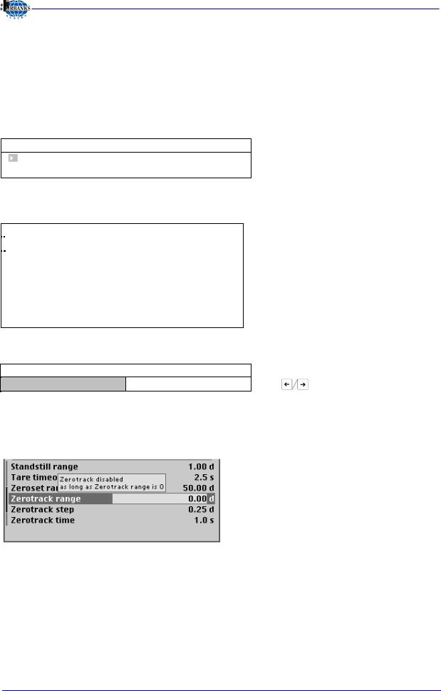
2.3.4Tool Tip (VNC)
The 'tool tip' indicates valid value ranges or important properties in a pop-up window, see example:
This is a warning, that the zero tracking is not activated, if the Zerotrack time is set to 0.
10/08 |
15 |
51207 Revision 1 |

Section 2: Process Indicator
2.3.5System Messages during Input (VNC)
The following types of messages are displayed as confirmation prompts / warnings during input:
Question mark
A question mark indicates that a choice of options (e.g. [Save] for saving or [Undo] for cancelling) is available.
“Stop“
An important indication that an action cannot be executed (e.g., if saving is not possible because the CAL switch is closed). Read the description and press [OK] to continue:
Processing is in progress
If an action takes a long time (e.g., Max for setting the full scale deflection), a clock symbol is shown.
Warning
A warning is marked by three exclamation points.
Informational text
An informational text is marked by one exclamation point.
Execution message
Successful execution of an action is indicated by a checkmark.
The graphics are not always included when system messages are depicted in this manual.
10/08 |
16 |
51207 Revision 1 |

Section 2: Process Indicator
2.3.6Overview of Accessories
10/08 |
17 |
51207 Revision 1 |

Section 2: Process Indicator
2.3.7Plug-in Cards
On the main board, the PR 5410 Process Indicator can be fitted with up to 2 plug-in cards. Mounting different types of cards on Slots 1 and 2 is mandatory (exception: PR 5510/04)!
If a card is fitted on Slot 4, only one more card may be mounted on Slots 1 or 2.
Product |
Function |
Position |
|
PR 5510/02 |
Protocols and parameters are adjustable |
Slot 1 or 2 |
|
2 serial RS-232 interfaces |
via software. |
||
|
|||
PR 5510/04 |
The serial RS-485/-422 interface is |
|
|
1 serial RS-232 interface and |
configurable using DIL switches on the |
Slot 1 and/or |
|
1 serial RS-485/RS-422 interface. |
card. Protocols can be selected via |
2 |
|
|
software. |
|
|
PR 5510/07 |
16-bit analog output, 0/4 - 20 mA. |
|
|
1 analog output, |
Input: 4 channels with common ground, |
Slot 1 or 2 |
|
4 analog inputs |
3000 d resolution (max. 1 card) |
|
|
PR 5510/08 |
Output: 5 decades + plus or minus sign or |
Slot 1 or 2 |
|
BCD output |
3 bytes binary, open emitter. 1 input |
|
|
PR 5510/09 |
Output: 5 decades + plus or minus sign, |
Slot 1 or 2 |
|
BCD output |
or 3 bytes binary, open collector. 1 input |
||
|
|||
PR 5510/12 |
Digital interfaces electrically isolated via |
|
|
6 optocoupler inputs and |
Slot 1 or 2 |
||
optocouplers. Passive inputs and outputs. |
|||
12 optocoupler outputs |
|
|
|
|
|
|
|
PR 5510/14 |
10 / 100 Mbit/s Modbus TCP |
Slot 4 |
|
Ethernet |
|||
|
|
||
PR 1721/31 |
Profibus-DP to IEC 61158 with |
Slot 4 |
|
Profibus-DP slave |
max. 12 Mbit/s |
||
|
|||
PR 1721/32 |
Interbus-S slave with up to 2 Mbit/s |
Slot 4 |
|
Interbus-S slave |
|||
|
|
||
PR 1721/34 |
DeviceNet slave with max. 500 kbit/s |
Slot 4 |
|
DeviceNet slave |
|||
|
|
||
PR 1721/37 |
10 / 100 Mbit/s EtherNet/IP |
Slot 4 |
|
EtherNet/IP |
|||
|
|
For product details, see chapter 3.3.3 .
10/08 |
18 |
51207 Revision 1 |

Section 3: Installing the Instrument and Plug-In Cards
3 Installing the Instrument and Plug-in Cards
Before starting work, please read Chapter 1 and follow all instructions.
Further procedures:
∙Check the consignment: unpack the components specific to the application.
∙Safety check: inspect all components for damage.
∙Make sure the on-site installation is correct and complete including cables, e.g. power cable fuse protection, load cells, cable junction box, data cable, console/cabinet, etc.
∙Follow the instructions for installation of the unit relating to application, safety, ventilation, sealing and environmental influences).
∙If necessary, mount the plug-in cards (instrument must be disconnected from all voltage sources).
∙Connect the cable from cable junction box or platform/load cell.
∙If applicable: connect other data cables, power cable, etc.
∙Connect the instrument power cable.
∙Check the installation.
3.1MECHANICAL PREPARATION
For cabinet or panel mounting, a corresponding cut-out for the housing must be provided (see Chapter 2.2).
Have all required parts, technical documents and tools at hand for mounting. Secure the cable at the place of installation; e.g., using cable ties. Remove the insulation from the cable ends, keep the strands short and fit them with ferrules.
3.2HARDWARE CONSTRUCTION
The electronics are contained on two printed circuit boards: the main board and the display board. The display board is connected to the main board by a plug.
3.3MAIN BOARD
The lithium battery (under the cover for the power supply) is always activated and energizes the calendar/clock module.
The main board holds the power supply and Slots 1, 2 and 4 for additional cards.
Load cell connector, serial interface, LAN adaptor, CAL switch as well as 3 inputs and outputs are accessible on the back panel.
Load cell |
RS-232 |
LAN CAL 3 inputs |
connector |
|
3 outputs |
10/08 |
19 |
51207 Revision 1 |

Section 3: Installing the Instrument and Plug-In Cards
3.3.1Network Port
The network port is built in as standard equipment. The port contains powerful TCP/IP connection circuitry with transfer rates of 10 or 100 Mbit/sec. The LEDs on the connector indicate whether the port is functioning.
|
Transfer rate: |
10 Mbit/s, 100Mbit/s, |
|
|
full / half duplex, auto-detection |
|
Connection method: Point to point |
|
|
Cable: |
CAT 5 patch cable, shielded twisted |
|
|
pair |
|
Cable impedance: |
150 ohms |
|
|
|
|
Electrical isolation: |
Yes |
|
|
|
|
Cable length : |
Max. 115 m |
|
Connection : |
RJ-45 socket on back panel of housing |
|
|
|
Remote operation of the PR 5410 indicator from the PC is possible; install version 3.3.7 VNC program on the PC. For setting the network address, see Chapter 4.2.4.
3.3.2Standard RS-232 Interface
The instrument is provided with a built-in RS-232 interface that is accessible on the back panel of the housing. This interface is configurable, and can be used, for example, for data transmission to a remote display or a printer.
|
|
|
|
|
|
|
|
Number of |
1 |
|
|
|
|
|
|
|
|
channels: |
|
|
|
|
|
|
|
|
|
Type: |
RS-232, full duplex |
|
|
|
|
|
|
|
|
Transfer rate: |
300 to 115K2 bit/s |
|
|
|
|
|
|
|
|
Parity: |
none, odd, even |
|
|
|
|
|
|
|
|
Data bits: |
7 / 8 bits |
|
|
|
|
|
|
|
|
Input signal level: |
logic 1 (high) - 3 ... - 15 V |
|
|
|
|
|
|
|
|
|
logic 0 (low) + 3 ... + 15 V |
|
|
|
|
|
|
|
|
Output signal level: |
logic 1 (high) - 5 ... - 15 V |
|
|
|
|
|
|
|
|
|
logic 0 (low) + 5 ... + 15 V |
|
|
|
|
|
|
|
|
Number of signals: |
2 output signals (TXD, |
|
|
|
|
|
|
|
|
||
|
|
|
|
|
|
|
|
|
RTS) |
|
|
|
|
|
|
|
|
|
2 input signals (RXD, CTS) |
|
|
|
|
|
|
|
|
Electrical isolation: |
none |
|
|
|
|
|
|
|
|
Cable type: |
shielded twisted pair |
|
|
|
|
|
|
|
|
|
(e.g. LifYCY 3x2x0,20), |
|
|
|
|
|
|
|
|
|
1 pair of wires for GND |
|
|
|
|
|
|
|
|
|
|
|
|
|
|
|
|
|
|
|
|
|
|
|
|
|
|
|
|
|
|
Connection: |
9-pin D-Sub socket (female) |
Cable length: |
max. 15 m |
||||||
10/08 |
20 |
51207 Revision 1 |
Section 3: Installing the Instrument and Plug-In Cards
Connecting a Remote Display / Remote Terminal
A PR 1627 remote display or a PR 1628 remote terminal can be connected to the built-in RS-232 interface [Builtin RS232] or to the PR 5510/04 card.
Press  -[Serial ports parameters]-[Remote display]-[Builtin RS232]-[Param] and select [Baudrate] 4800. The baud rate now corresponds to the default settings of PR 1627 or PR 1628. The following settings cannot be changed: [Bits] 7, [Parity] even and [Stopbits] 1.
If only one instrument is connected to a PR1627/8, [Mode] must be [single transmitter].
When connecting several instruments to a PR 1628 via an RS-232/RS-485 converter, selection for display on PR 1628 is possible using addresses. For this purpose, select [multiple transmitters] as [Mode] in all instruments, enter the instrument address under [Device Id] and the address of the subsequent instrument under [Next Device Id].
Connecting a YDP12IS or YDP04IS Ticket Printer
The ticket printer YDP12IS-OCEUV or YDP04IS-OCEUV can be connected via [Builtin RS232] interface or the RS-232 on card PR 5510/04.
If the printer is connected to the [Builtin RS232] port:
Press  -[Serial ports parameter]-[Printer]-[Builtin RS232]-[Param] and configure the following settings under [Protocol]: [RTS/CTS], [Baudrate]: 9600, [Bits]: 8, [Parity]: [none], [Stopbits]: 1 and [Output mode]: [Raw].
The printer must be set to Line Mode (factory setting: Page Mode). Press the 'FEED' button to change modes; please refer to the installation instructions delivered with the printer.
10/08 |
21 |
51207 Revision 1 |

Section 3: Installing the Instrument and Plug-In Cards
3.3.3Optocoupler Inputs
The main board has 3 digital inputs for process control, electrically isolated by optocouplers, each bipolar potential-free.
|
|
|
|
Number of inputs: |
3 ( CH1, CH2, CH3 ) |
|
|
|
|
Input signal: |
Logic 0: 0 to 5 VDC or open |
|
|
|
|
|
Logic 1: 10 to 31 VDC |
|
|
|
|
|
Passive, external supply required |
|
|
|
|
Input current: |
< 7 mA @ 24 V |
|
|
|
|
|
< 3 mA @ 12 V |
|
|
|
|
|
Protected against incorrect polarity |
|
|
|
|
Electrical isolation: |
Yes, via optocoupler |
|
|
|
|
|
|
|
|
|
|
|
Plug-in 7-pin screw terminal block, |
|
|
|
|
Connection: |
cable shield connected to housing |
|
|
|
|
|
(terminal 14), max. 1.5 mm² cable. |
|
|
|
|
|
|
|
|
|
|
|
|
|
|
|
|
Cable: |
Shielded, max. 50 m |
|
|
|
|
||
|
|
|
|
|
|
Example: connection of a contact input
|
|
|
|
|
|
|
|
10/08 |
22 |
51207 Revision 1 |
|
Section 3: Installing the Instrument and Plug-In Cards
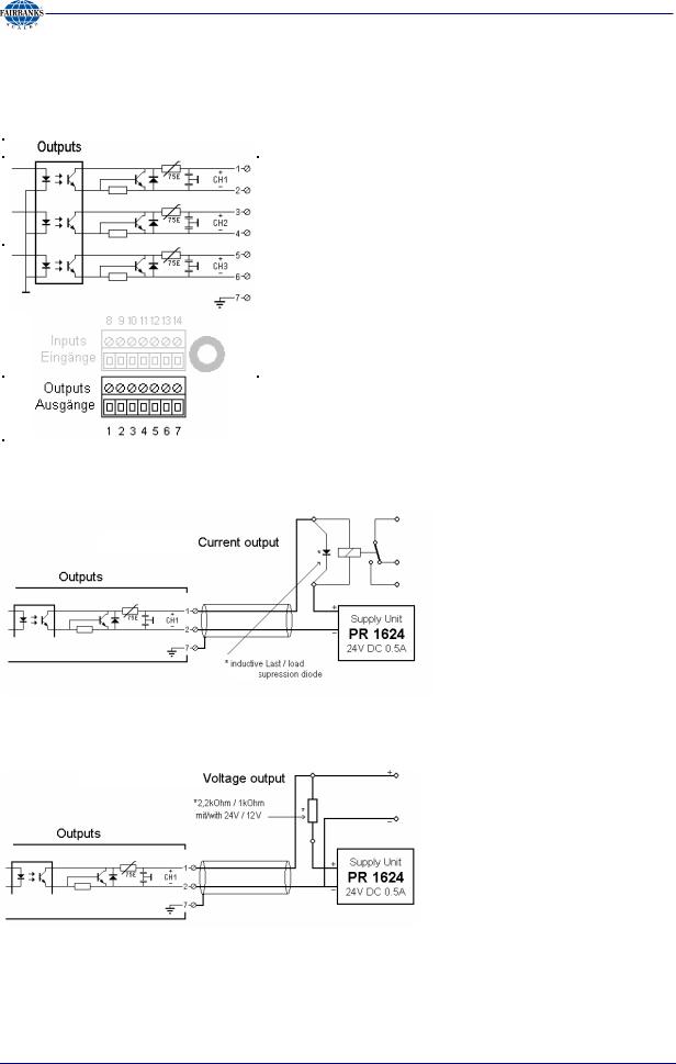
3.3.4Optocoupler Outputs
The main board has 3 digital outputs for process control, electrically isolated by optocouplers, each bipolar potential-free.
|
|
|
|
Number of outputs: |
3 ( CH1, CH2, CH3 ) |
|
|
|
|
Output: |
Max. switching voltage: 31 VDC, |
|
|
|
|
|
Protected against incorrect polarity |
|
|
|
|
|
Max. switching current: 25 mA |
|
|
|
|
|
Voltage drop @ 25 mA: 3 V |
|
|
|
|
|
Passive, external supply required |
|
|
|
|
Electrical isolation: |
Yes, via optocouplers |
|
|
|
|
|
|
|
|
|
|
|
Plug-in 7-pin terminal block, cable |
|
|
|
|
Connection: |
shield connected to housing |
|
|
|
|
|
(terminal 7), max 1.5 mm² cable |
|
|
|
|
|
|
|
|
|
|
|
|
|
|
|
|
Cable: |
Shielded, max. 50 m |
|
|
|
|
||
|
|
|
|
|
|
Example: connection of relay control
The relay switches, when the output is active (true). For protection of the output circuit, relays with free-wheel diode must be provided.
Example: connection of voltage output
When the output is active (true), the output voltage goes from 24 V / 12 V to < 3 V . The load resistance must be 2.2 kohms / 1 kohm.
10/08 |
23 |
51207 Revision 1 |

Section 3: Installing the Instrument and Plug-In Cards
3.4ACCESSORIES
3.4.1Installing Plug-in Cards
The main board has two slots with identical pin allocation (34 contact pins in two rows of 17) and another slot (34 contact pins in two rows of 17) for plug-in cards. The slot designations are “Slot 1 ...
2" and "Slot 4" (left). Up to 2 cards can be mounted. Accordingly, the back panel is provided with two cut-outs for the retainer plates of the cards.
Before installing or removing a plug-in card, disconnect the instrument from all voltage sources.
View from above, back panel connectors at the bottom
View from the back
Installation (Slots 1-2, 4):
The flat cables plug into connectors (Slots 1
... 2, 4) on the main board. The cables are polarized; i.e. incorrect polarity is precluded.
A description and examples of the various cards and connections are given in Chapter 3.3.3 .
Remove the dummies from the back panel (2 screws; M3) and replace them with the retainer plates for the plug-in cards.
The flat-cable connectors must be inserted into the corresponding slots on the main board.
After installation/modification, the plug-in cards are detected automatically.
To view a list of the installed plug-in cards, select  -[Show HW-slots]:
|
|
|
Info/HW-Slots |
|
|
||
|
|
|
|
Builtin |
RS 232 |
Built-in serial interface |
|
|
Slot |
1 |
|
PR |
|
RS 485/232 |
Slots (Slot 1 and 2) are identical |
|
|
5510/04 |
|
||||
|
|
|
|
|
|
|
|
|
Slot |
2 |
|
|
|
-empty- |
|
|
Slot |
3 |
|
Builtin |
Digital I/O |
Built-in digital I/Os |
|
|
Slot |
4 |
|
PR |
Profibus-DP |
|
|
|
1721/31 |
|
Only Fieldbus cards |
||||
|
|
|
|
|
|||
|
|
|
|
|
|
|
|
10/08 |
24 |
51207 Revision 1 |

Section 3: Installing the Instrument and Plug-In Cards
3.4.2Cable Connection in the D-Sub Connector Mating Plug
The connections on the back panel are plug-in type. Keep the conductors as short as possible and connect them to the terminals. The connector housings are conductive (metallized), i.e., part of the shield, and must be fastened to the back panel by screws.
Mounting a cable:
∙Open the connector housing (catches)
∙Release and open the cable clamp
∙Remove approx. 50-60 mm of the cable insulation
∙Shorten the shield to 5 mm and bend it over the cable sheath
∙Remove 3mm wire insulation and connect it by soldering
∙Insert the pin unit
∙Put the cable under the cable clamp
The grounding tongue presses on the shield bent backwards; the clamp presses on the cable sheath
∙Close and tighten the cable clamp
∙Check the strain relief
∙Insert the mounting screws on both sides
∙Close the connector housing (catches)
The shields must be connected to the metal housings on both ends of the cable.
10/08 |
25 |
51207 Revision 1 |

Section 3: Installing the Instrument and Plug-In Cards
3.4.3PR 5510/02 Serial I/O
The plug-in card contains two RS-232 channels (A and B), which can be used simultaneously and independently. Max. 2 PR 5510/02 cards can be plugged in (Slot 1 ... 2). The relevant interface
parameters are adjustable in  - [Serial ports parameter], no additional settings on the card are required.
|
|
|
Internal connection: |
34-pole connector socket |
|
|
|
|
|
|
|
|
Number of channels: |
2 |
|
|
|
Type: |
RS 232, full duplex |
|
|
|
Transfer rate: |
300 to 19k2 bits/sec |
|
|
|
Parity: |
No, odd, even |
|
|
|
Data bits: |
7 / 8 Bit |
|
|
|
Signals RS 232: |
Output: TX, RTS |
|
|
|
Input: RX, CTS |
|
|
|
|
|
|
|
|
|
Input signal level: |
logic 1 (high) - 3 ... - 15 V |
|
|
|
|
logic 0 (low) + 3 ... + 15 V |
|
|
|
Output signal level: |
logic 1 (high) - 5 ... - 15 V |
|
|
|
|
logic 0 (low) + 5 ... + 15 V |
|
|
|
Potential isolation: |
No |
|
|
|
Cable length: |
max. 15m |
|
|
|
Cable type: |
|
|
|
|
|
twisted pairs, screened |
|
|
|
|
(e.g. LifYCY 3x2x0,20), |
|
|
|
|
1 conductor pair for GND. |
|
|
|
|
|
|
|
|
External connection: |
2x D-Sub 9-pole socket |
|
|
|
|
|
|
|
|
|
(female) |
|
|
|
|
|
|
|
|
Accessories |
2x connector counterpart D-Sub |
|
|
|
(delivered with the |
9-pin (male) |
|
|
|
unit): |
incl. screening hoods |
|
|
|
Dimensions: |
86 x 52 x 15 mm |
|
|
|
(LxWxH): |
|
|
|
|
Weight: |
appr. 30 g |
|
|
|
|
|
|
|
|
|
|
|
|
|
|
|
|
|
|
|
|
The RS-232 can only be used as point to point connection. A max. cable length of 10-15m must not be exceeded.
The PR5510/02 and the 'Builtin' comply with the standard pin allocation, i.e. they are equal in the connecting diagrams. Accordingly, the RS232 connections are described only for the Builtin Interface in this manual (see chapter 3.3.2 ).
10/08 |
26 |
51207 Revision 1 |

Section 3: Installing the Instrument and Plug-In Cards
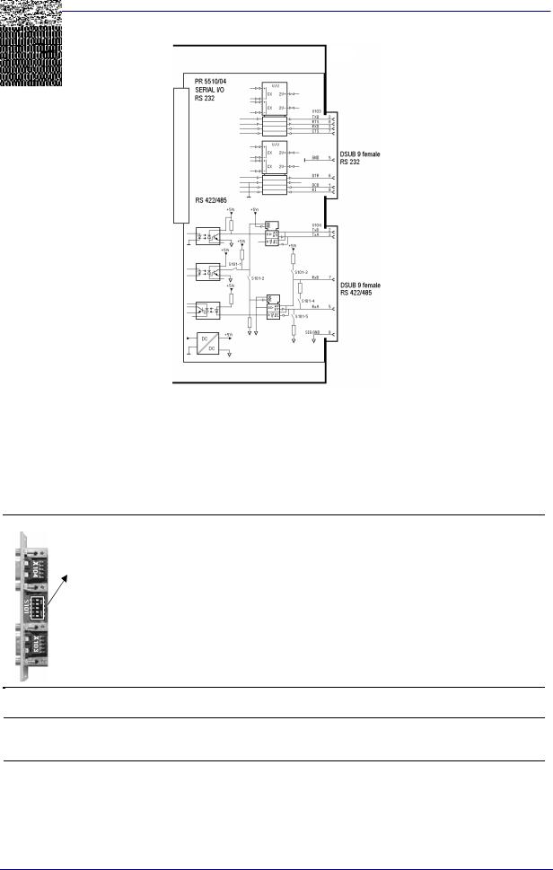
3.4.4PR 5510/04 Serial I/O
The plug-in card has two channels (1x RS-232 and 1x RS-422/485), which can be used simultaneously and to a great extent independently. The RS-422/485 interface is electrically isolated. Up to 2 PR 5510/04 cards (Slot 1 and 2) can be plugged in. The relevant interface
parameters can be configured under  -[Serial ports parameter]; the DIL switch S101 must be set for RS-422/485 additionally.
|
Internal connection: |
34-contact socket terminal strip |
|
|
Number of channels: |
1x RS-232, 1x RS-422/485 |
|
|
Type: |
RS-232 |
full duplex |
|
|
RS-422/485 full duplex (4-wire) |
|
|
|
* |
|
|
|
RS-485 |
half duplex (2-wire) |
|
|
* |
|
|
Transfer rate: |
300 to 19k2 bit/s |
|
|
RS-232C (V24) |
Output: TXD, RTS, DTR |
|
|
signals: |
Input: RXD, CTS, DCD, RI |
|
|
RS-422/485 signals: |
TxA, RxA, TxB, RxB |
|
|
Electrical isolation: |
RS-232: no, RS-422 / 485: yes |
|
|
Cable length: |
Max. 15m with RS-232 |
|
|
Max. 1000 m with RS-422 / 485 |
||
|
|
||
|
Cable type: |
Shielded twisted pair |
|
|
|
(e.g., LifYCY 3x2x0,20), |
|
|
|
1 conductor pair for GND. |
|
|
External connection: |
2 D-Sub 9-contact female |
|
|
|
connectors |
|
|
|
|
|
|
Accessories |
2 D-Sub 9-pin mating plugs |
|
|
(delivered with the |
(male) |
|
|
unit): |
incl. shielded housing |
|
|
Dimensions: |
86 x 52 x 15 mm |
|
|
(LxWxH): |
|
|
|
Weight: |
33 g |
|
PR 5510/04 RS-232
The RS-232 interface is independent of the S101 switch settings.
It can be used only for point-to-point connection.
PR 5510/04 is provided as an equivalent to the [Builtin RS-232] interface in the RS-232 channel with additional signals: DCD, DTR, RI.
The built-in and PR 5510/04 interfaces comply with the standard pin allocation; i.e., they are equivalent in the following connecting diagrams. Thus only the RS-232 connections for the built-in interface are described in this manual (see Chapter 3.3.2).
10/08 |
27 |
51207 Revision 1 |
Section 3: Installing the Instrument and Plug-In Cards
PR 5510/04 RS-422/485
When mounting, the RS-485/422 interface must be configured by DIL switch S101 on the card. Using RS-485 is compulsory with a multi-point connection (tristate status). The RS-485 interface can be used also for point-to-point connection. Like 2-wire or 4-wire connections, this is dependent on the other communicating units.
A 2-wire connection is half-duplex and cannot send and receive simultaneously. It requires corresponding driver programming (see relevant instrument manual).
Factory setting |
Switch S101 |
Settings for RS-422/ 485 |
|
|
|||
1: |
Tristate enable: |
OFF – RS-422 |
ON – RS-485 |
|
|||
|
|
|
|
|
|
|
|
|
|
2: |
Rx enable |
OFF – 4-wire |
ON – 2-wire |
|
|
|
|
|
|
|
|
||
|
|
3: |
Rx pull-up resistor: |
OFF – not connected |
ON - (RxB 1k54 |
+V) |
|
|
|
|
|
|
|
|
|
|
|
4: |
Rx bus termination: |
OFF – not connected |
ON - (RxA |
205E |
|
|
|
|
|
|
RxB) |
|
|
|
|
5: |
Rx pull-down resistor: OFF – not connected |
ON - (RxA |
1k54 |
-V) |
|
Overview of which switches must be closed (ON) for which mode:
S101
Master
Two-wire system |
|
Four-wire system |
|
Point to point |
Bus |
Point to point |
Bus |
RS-485 |
RS-485 |
RS-422 |
RS-422 |
1, 2, 3, 4, 5 = |
1, 2, 3, 4, 5 = on |
4 = on |
3, 4, 5 = on |
on |
|
|
|
Individual slave |
RS-485 |
- |
RS-422 |
- |
|
1, 2 = on |
|
4 = on |
|
Other slaves |
- |
RS-485 |
- |
RS-485 |
|
|
1, 2 = on |
|
1 = on (default) |
Last slave |
- |
RS-485 |
- |
RS-485 |
|
|
1, 2, 3, 4, 5 = on |
|
1, 3, 4, 5 = on |
10/08 |
28 |
51207 Revision 1 |
Section 3: Installing the Instrument and Plug-In Cards
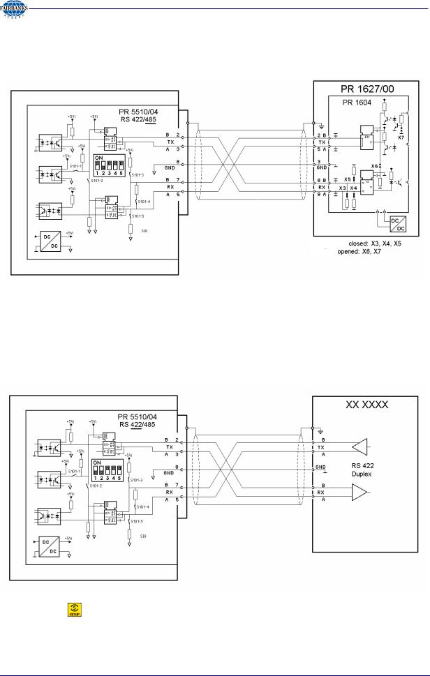
Connecting a PR 1627 Remote Display over RS-485
Four-wire transmission, point to point, full duplex (simultaneous sending and receiving possible) with PR 1627/00 remote display.
Configuration:  -[Serial ports parameter]-[Remote display]-[Slot1/2-RS-485]
RS-422 Point-to-Point Connection (Four-Wire)
Four-wire transmission: full duplex (simultaneous sending and receiving possible) RS-422 can be used only for point-to-point connection.
Configuration: |
-[Serial ports parameter]-[......... |
]-[Slot1/2-RS-485] |
10/08 |
29 |
51207 Revision 1 |

Section 3: Installing the Instrument and Plug-In Cards
Connecting Several PR 1627 Remote Displays over RS-485
Connection of several PR 1627 remote displays over RS-485, four-wire, full-duplex (simultaneous sending and receiving possible):
|
|
|
|
|
|
|
|
|
|
|
|
|
|
|
|
|
|
|
|
|
|
|
|
|
|
|
|
|
|
|
|
|
|
|
|
|
|
|
|
|
|
|
|
|
|
|
|
|
|
|
|
|
|
|
|
|
|
|
|
|
|
|
|
|
|
|
|
|
|
|
|
|
|
|
|
|
|
|
|
|
|
|
|
10/08 |
30 |
|
|
|
|
51207 Revision 1 |
 Loading...