

Page 1
Installation Manual
TRACKER SERIES
TRUCK SCALE
MODEL: VS SERIES
VSX SERIES
© 2008-2012 by Fairbanks Scales, Inc.
All rights reserved Revision 8 04/12
51173
Page 2

DISCLAIMER
Every effort has been made to provide complete and accurate information in this manual. However,
although this manual may include a specifically identified warranty notice for the product, Fairbanks
Scales m akes no representatio ns or warranties with res pec t t o the contents of this manual, and reserves
the right to make changes to this manual without notice when and as improvements are made.
Fairbanks Scales shall not be liable for any los s, damage, cost of repairs, incide ntal or consequen tial
damages of any kind, whether or not based on express or implied warrant y, contract, negligence, or
strict liability arising in connection with the design, development, installation, or use of a scale.
© Copyright 2008- 2012
This document contains proprietary information protected by copyright. All rights are reserved; no part
of this manual may be reproduced, copied, translated, or transmitted in any form or by any means
without prior written permission of the manufacturer.
Page 3

Amendment Record
TRACKER SERIES TRUCK SCALE
INSTALLATION MANUAL
Document 51173
Manufactured by Fairbanks Scales, Inc.
821 Locust
Kansas City, Missouri 64106
Created 02/2008
Revision 1 04/2008 Released doc ument
Revision 2 08/2009 Added product improvements
Revision 3 10/2009 Revised deck construction instructions
Revision 4 03/2010 Updated manual per engineering request for deck construction
and parts description correction.
Revision 5 08/2010 Corrected drawing in Appendix I
Revision 6 11/2010 Updated shoring images.
Revision 7 03/2011 Updated module assembly drawings
Revision 8 04/2012 Updated images and assembl y instructions.
Page 4

Table of Contents
SECTION 1: GENERAL INFORMATION ........................................................... 6
Introduction .................................................................. 6
Description .................................................................. 6
Rocker Column Load Cell Systems .............................................. 6
Fairbanks Service Policies ...................................................... 7
Physical Installation Notes .................................................... 7
Electronic Component Care ................................................... 9
Conferring with Our Client ..................................................... 9
Phases of Installation ......................................................... 10
Pre-Installation Checklist ..................................................... 10
Unpacking ............................................................... 10
Equipment Location ........................................................ 11
Safety ................................................................. 12
Users’ Responsibilities ...................................................... 12
SECTION 2: INSTALLATION ......................................................... 13
Overall Steps ............................................................... 13
Tools, Equipment, and Mat erials ............................................... 13
Site Preparation ............................................................. 14
Module Assembly ............................................................ 15
Deck Construction ......................................................... 20
Adjusting the Scale after the Pour .............................................. 23
Installing Load Cells ........................................................ 23
Load cell cables ............................................................. 24
SECTION 3: WIRIN G FO R INTALOGIX™ SYSTEMS .......................................... 26
Introduction ................................................................. 26
Description ................................................................. 26
Installation ................................................................. 26
Boxes ................................................................. 26
Smart Sectional Controllers (SSC) ............................................. 26
Load Cell Wiring ............................................................. 27
Cell Numbering ............................................................ 27
Installing Load Cells ........................................................ 28
Dip (Address) Switch Setup, Smart Sectional Controllers (SSC) ....................... 30
Wiring the Power Supply ....................................................... 31
Grounding the Scale .......................................................... 32
Data Recording .............................................................. 33
04/12 4 51173 Rev. 8
Page 5

Table of Cont ents
SECTION 4: CALIBRATION .......................................................... 34
Initial Zero and Span Adjustments ................................................ 34
Repeatability and Return-to-Zero Performance Tests ............................... 34
Section Test and Adjustment, Intalogix™ Technology Systems ........................ 35
Digital indicator initial and span calibration Intalogix™ Technology ...................... 35
SECTION 5: PARTS .............................................................. 36
Scale Components ........................................................... 36
Load Cells and Load Cell Hardware .............................................. 36
Intalogix™ Technology Scale Components ......................................... 37
APPENDIX I: WIRING DIA G RAM ..................................................... 38
APPENDIX II: DATA RECORDING .................................................... 39
APPENDIX III: PARTS FOR MODELS PRIOR TO 08/2009
.................................... 39
04/12 5 51173 Rev. 8
Page 6

Section 1: General Information
INTRODUCTION
The Tracker Series is a uniquely designed truck scale, combining the proven
reliability of an environmentally sealed load cell system with the added benefit of an
above grade, low profile, incorporated side rail, concrete deck design. The Tracker
Series is a field assembled style scale featuring compact shipment and ready for
module assembly.
DESCRIPTION
The Tracker Weighbridge consists of one or more field assembled modules with a
field poured concrete deck.
The weighbridge design consists of a pair main girder beams prov idi ng long i tudi nal
strength while acting as safety side rails.
Cross members are bolted between the main girders providing lateral strength and
forming up the concrete deck.
The low profile foundation design offers many benefits over the traditional scale pit
design including reduced construction costs and simplified maintenance.
With the scale installed completely above ground, the load cell system, suspension
components, and weighbridge are not subject to the harsh corrosive environment
found in a scale pit.
Designed to meet or exceed National Institute of Standards and
Technology (NIST) Handbook H-44
requirements for Class IIIL Devices.
Rocker Column Load Cell Systems
The load cell system incorporates environmentally sealed, rocker column load cells.
Components within the load cell suspension system are zinc plated for maximum
corrosion protection. Each component is field replaceable.
The load cells are hermetically sealed, completely enclosing the internal strain gage
cavity providing environmental protection and ensuring long life.
04/12 6 51173 Rev. 8
Page 7

Section 1: Gen er al Informatio n
Absolutely no physical, electrical or program modifications othe r
FAIRBANKS SERVICE POLICIES
Prior to installation, always verify that the
equipment satisfies the customer's
requirements as supplied, and as described
in this manual.
If the equipment cannot satisfy the
application and the application cannot be
modified to meet the design parameters
of the equipment, the installation
should NOT be attempted.
It is the customer/operator's responsibility to ensure the
equipment provided by Fairbanks is operated within the parameters
of the equipment's speci fi c a ti ons and pr ot ec t e d fr om ac c idental or
malicious damage.
WARNING!
than selection of standard options and accessories can be made
by customers to this equipment
Repairs are performed by Fairbanks Scales Service Technicians
and Authorized Distri but or P er s onne l ONLY!
Failure to comply with this poli c y voids al l im pli e d a nd/or written
warranties
Physical Installation Notes
Check all devices for proper operation. If any error messages occur, refer to
Troubleshooting or the proper ma nual of that device.
Only those charges which are incurred as a result of the equipment's inability
to be adjusted to performance specifications may be charged to warranty.
No physical alterations (mounting holes, etc.) are allowed during installation.
04/12 7 51173 Rev. 8
Page 8

Section 1: Gen er al Informatio n
Physical Installation Note s , Continued
The installing technici a n is res pons ible that all personnel are fully
trained and familiar wit h the equipment's capabilities and
limitations before the installation is considered complete.
IMPORTANT NOTICE:
1. Al l load cells, load cell cables and interconnecting cables used to
connect all scale components (such as digital weight indicators, junction
boxes, sectional controllers, and power supplies) and peripheral devices
(such as printers, remote displays, relay boxes, remote terminals, card
readers, and auxiliary data entry devices) including the scale
components themselves shall be located a minimum of 36 inches
distance away from all single and multiple phase high energy circuits
and electric current carrying conductors, such as 120 volt AC, 220 volt
AC, 480 volt AC and electric supply of higher voltage wiring runs and
stations, AC power transformers, overhead or buried cables, electric
distribution panels, electric motors, florescent and high intensity lighting
which utilize ballast assemblies, electric heating equipment, traffic light
wiring and power, and relay boxes.
2. All scale components including digital weight indicators and
peripheral devices are not designed to operate on internal combustion
engine driven electric generators and other similar equipment.
3. Electric arc welding can severely damage scale components such
as digital weight indicators, junction boxes, balance boards, sectional
controllers, power supplies, and load cells.
4. Communications which utilize RS232 serial communication is
limited to 50 cable feet distance.
For additional information, please contact your Fairbanks Scales
Representative.
04/12 8 51173 Rev. 8
Page 9

Section 1: Gen er al Informatio n
Electronic Component Car e
Much of the equipment consists of printed circuit assemblies, which must be
installed using ESD handling procedures.
These assemblies must be replaced as ass e mbli es or units.
Replacement of individual components is not allowed.
The assemblies must be properly packaged in ESD protective material.
These components must be returned intact for replacement credit per normal
procedures.
All electronic and mechani cal adj ustments are considered to be part of the
installation, and are included in the installation charge(s).
Included is any required computer programming or upgrades.
Included are any accuracy and/or operational specification changes.
Do not remove power from this unit unless it is performed by the proper shut down
method. Failure to comply with the proper shut down procedures can result in
damage to the hard disk drives or data.
The AC receptacle / outlet shall be located near the instrument and easily accessible.
Electrical connections other than those specified may not be performed.
Conferring with Our Client
Before the installation i s cons idered complete, the equipment is to
be programmed to meet or exceed any applicable weights and
measures requirements.
The technician must be prepared to recommend the arrangement of components
which provide the most efficient layout, utilizing the equipment to the best possible
advantage.
The warranty policy must be explained and reviewed with the customer.
04/12 9 51173 Rev. 8
Page 10

Section 1: Gen er al Informatio n
PHASES OF INSTALLATION
The complete install ati on c ons is t s of the f ollowing phases:
A. Pre-Installation Checklist
B. Unpacking
C. Equipment location
D. Safety
E. User Responsibil ity
F. Installation
G. Calibration
Pre-Installation Checklist
The following points should be checked and discussed with the Area Sales Manager
and/or customer, if necessary, before the technician goes to the site and installs the
equipment.
Check the customer's application to make certain it is within the capabilities and
design parameters of the equipment.
If the installation process might disrupt normal business
operations, tell the customer and ask that they make ample
arrangements.
Is properly-grounded power available at the installation
location?
Be sure that the equipment operator(s) are available for
training.
The Service Technician must thoroughly review the installation procedures.
The service technician reviews the recommended setup with the Area Sales
Manager or Area Service Manager, and together they identify all necessary
variations to satisfy the customer's particular application.
Unpacking
Follow these guidelines when unpacking all equipme nt:
Check in all components and accessories according to the customer's order.
04/12 10 51173 Rev. 8
Page 11

Section 1: Gen er al Informatio n
Unpacking, Continued
Remove all components from their packing material, checking against the invoice
that they are accounted for and not damag e d .
▪ Advise the shipper immediately, if damage has occurred.
▪ Order any parts necessary to replace those which have been damaged.
▪ Keep the shipping container and packing material for future use.
▪ Check the packing list.
Collect all necessary installation manuals for the equipment
and accessories.
Open the equipment and perform an inspection, making
certain that all hardware, electrical connections, and printed
circuit assemblies are secure.
Do not reinstall the cover if the final installation is to be
performed after the pre-installation checkout.
Equipment Location
Position the equipment with these points in mind:
Intense direct sunlight can harm the display.
Do not locate near magnetic material or
equipment/instruments which use magnets in their design.
Avoid areas which have extreme variations in room temperatures. Temperat ures
outside the instrument’s specifications will affect the weighing accuracy of this
product.
04/12 11 51173 Rev. 8
Page 12

Section 1: Gen er al Informatio n
Safety
Follow these safety precautions during operation:
Do not load the platform if there is any evidence of
damage to the platform or supporting structure.
Use safety chains or other suitable restraining devices if
there is any possibility of the load shifting, falling, or rolling
from its position on the platform.
Users’ Responsibilit ie s
All electronic and mechanical calibrations and/or adjustments required for making
this equipment perform to accuracy and operational specifications are considered
to be part of the installation.
They are included in the installation charge.
Only those charges which are incurred as a result of the equipment's inability
to be adjusted or calibrated to per for ma nc e spec ifications may be charged to
warranty.
Absolutely no physical, electrical or program modifications other than selection of
standard options and accessories are to be m ade to thi s equipment.
Electrical connections other than those specified may not be performed , and
physical alterations (holes, etc.) are not allowed.
The equipment consists of printed circuit assemblies which must be handled
using ESD handling procedures, and must be replaced as units.
Replacement of individual components is not allowed.
The assemblies must be properly packaged in ESD protective material and
returned intact for replacement credit
per normal procedures .
04/12 12 51173 Rev. 8
Page 13
MUST reserve a Crane in advan c e
Section 2: Installation
OVERALL STEPS
A. Foundation check, layout, and bas e plate setting
B. Preparing tools, materials, documentation and renting a crane.
C. Setting up the modules
D. Setting the modules on load cells.
E. Wiring
F. Calibrating and Testing
Tools, Equipment and Materi a ls
Certified Prints
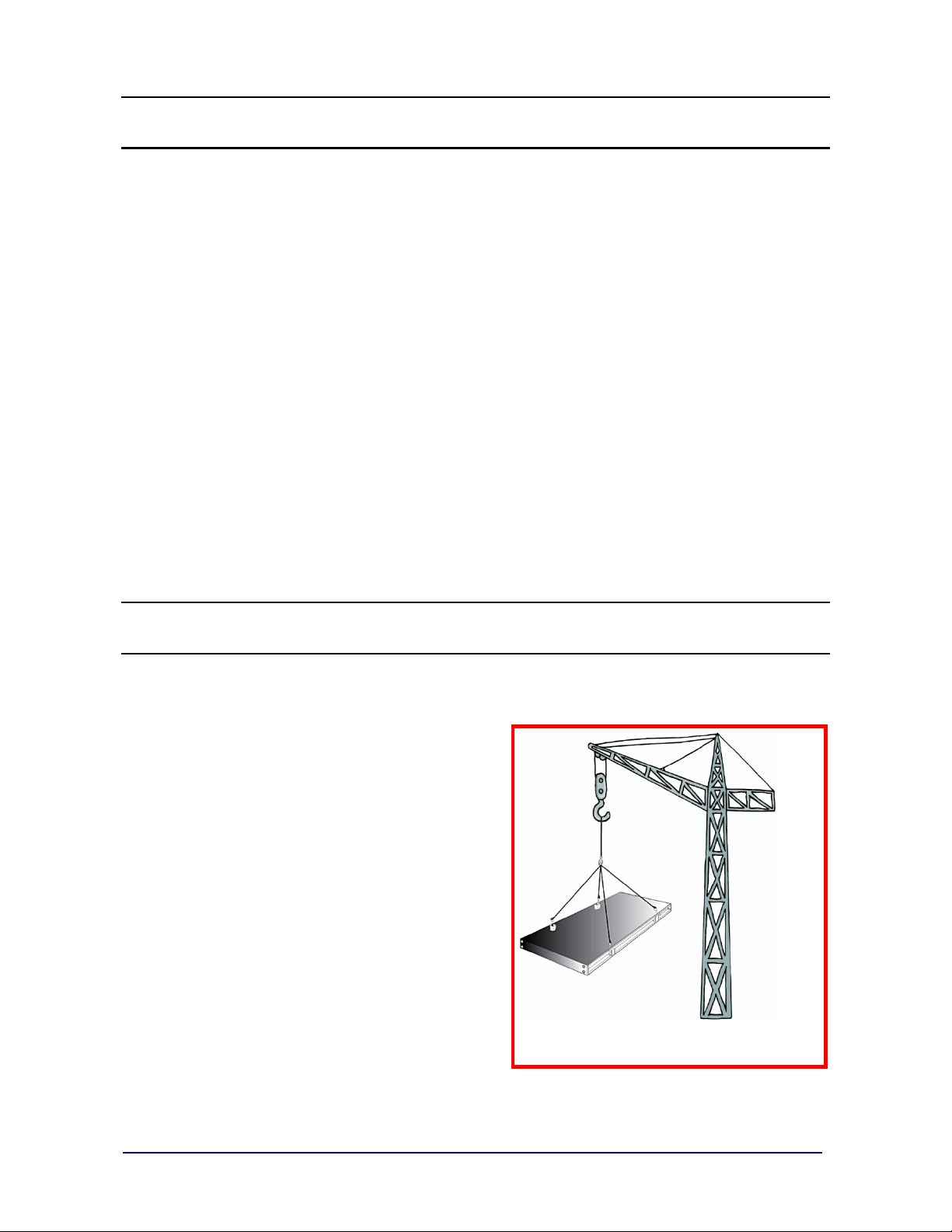
A mobile crane of sufficient lifting capacity to safely lift and place the main beams
which are approximately 2000 lbs.
Four equal length twenty foot (4-20 ft.) li fting chai ns or cables with hooks.
IMPORTANT NOTE: The installer MUST reserve Crane and Chains/Cables in
advance from a local rental service company.
Hand tools.
Hydraulic jacks.
Two fifteen ton (15 ton) hydraulic
jacks.
100' steel tape measure.
String line or chalk line (both)
Pry bars.
04/12 13 51173 Rev. 8
Page 14

Section 2: Installation
SITE PREPARATION
1. Assist the customer in selecting a site which allows
easy access to and from the scale, ensuring enough
area for straight and level approaches, and to meet
all State and Local Weights and Measures
Regulations.
Refer to the serial tag located on the scale to
determine the capacity of the scale to be installed.
Use only certified prints for all concrete work.
The site needs good drainage away from the
scale, elevated enough so the surrounding areas
drain away from the scale site.
The soil must have a minimum bearing pressure of 3000 PSF, or as specified
on the foundation drawing s supplied by Fairbanks Scales for the scale to be
installed.
Obtain all the necessary permits and licenses prior to beginning construction.
NOTE: Always… “CALL BEFORE YOU DIG.”
1-888-258-0808
2. Using a transit, sight in and mark with stakes the area where the placement is to
occur, and where supports, forms, or concrete are to be built.
When constructing forms, make sure they are plumb, square, and level.
Place and compact gravel into the base of the forms, if necessary.
Cut and position rebar into the forms as per the schedule detailed on the
foundation prints supplied by F ai rbank s S cal e s for the scale being installed
3. The scale is designed so it may be anchored to the foundation through the use of
expansion anchors (included) which are inserted into the concrete after it has
cured.
Expansion anchors are recommended due to the flexibility provided in final
positioning of the scale.
The hold down force of ex pans ion anchors meet or exceed that of pour ed in
place anchors.
4. Pour concrete, using a mix to yield a minimum 4000 PSI. Vibrate t he concrete
into position to ensure consiste nc y.
All concrete work should conform to standards set forth by the American
Concrete Institute Code.
Allow concrete to cure for several days before erecting the scale.
04/12 14 51173 Rev. 8
Page 15

Section 2: Installation
SITE PREPARATION, CONTINUED
5. Remove forms and backfill for proper drainage. A slope away from the scale
is recommended.
Allow concrete to cure for 28 days or until a test cylinder indicates the
concrete has reached its design strength before allowing traffic on the scale.
MODULE ASSEMBLY
The Tracker scale is shipped as a bundle of steel beams and hardware that are
ready to be assembled on the jobsite.
Lay Out the Foundation
1. Determine the centerline of the foundation and mark that line along the length of
the scale with a chalk line.
2. Measure from the centerline to establish the centerlines of the load cells and the
centerlines of the anchor locations. Mark these along the length of the scale with
a chalk line as well. Reference the certified print for load cell locations and anchor
locations.
3. Place base plates into approximate locations. Have locating tools and shoring
timbers ready at each location. Load cell assemblies will be moved into final
position only after the deck concrete is cured.
Figure 2-1
04/12 15 51173 Rev. 8
Page 16

Section 2: Installation
Place Main Beams
1. Move the beams close to their approximate locations. All girders with j-box
mounting bars should be on the same side, nearest the scale house.
2. To identify your beams, see Figure 2-2. If there are several interior beams,
consult the certified print for the correct placement order.
Figure 2-2
Assemble the Left Hand Base Module
1. Set the left hand base girders first (both J-Box and Plain sides).
a. To begin, set girders on shoring timbers. The beams and modules should
remain on shoring timbers until the all modules are assembled and all
module connection hardware is fully tightened. DO NOT use locating
tools at this stage.
b. Center the left hand end base girders on the load cell centerline and put
the end of the beams with the check block against the end wall.
04/12 16 51173 Rev. 8
Page 17

Section 2: Installation
Assemble the Left Hand Base Module, continued
2. Install the cross members.
a. There are two (2) different types of cross members. See Table 2-1 to
identify them.
b. Place the appropriate cross members at the appropriate location. The
channel should be tow ard th e botto m. The cross member should sit on top
of the bar on the girder flange.
c. Loosely bolt each end of the cross member to the main girder including
one spring lock washer per bolt. Do not fully tighten.
d. The cross member bolt head should be at the exterior side of the main
girder.
Cross Section View Installation Locations
One at each end of every
module.
At each through web bolt
hole location.
Table 2-1
04/12 17 51173 Rev. 8
Page 18

Section 2: Installation
Assemble the Remaining Modules One at a Time
1. Set the second beams (both J-Box and Plain sides).
a. The end of the beams without an upper receiver plate should rest on the
receiver plate protruding from the base girder. Center the girder on the
load cell centerline and set on shoring timbers.
b. Align the hole in the flange of the interior beam with the hole in the receiver
plate on the base girder. Loosely bolt this connection, but do not fully
tighten.
c. At the joint where the two beams meet, install the threaded rod through the
center hole in the beam stiffeners, and through the 3/4" spacer pipe, which
fits between the stiffeners. Loosely install two nuts and one washer on
each end of the connection rod. Do not fully tighten.
2. Install the cross members as directed above.
3. Repeat these steps for each subsequent module until the final right hand end
modules is assembled.
Completing the Scale Assembly before Pour
1. Once all modules are assembled, check the square of the scale and adjust as
necessary to bring the scale into square.
2. Tighten all cross member bolts one-half turn past snug (min 350-425 ft-lbs).
3. Tighten all connection bolts that bolt through the flanges and load cell upper
receiver plates.
4. Tighten the bolts on all girder connection bolts (through the stiffeners) and ensure
that the jam nuts are secured.
5. Check scale square again.
6. Install locating tools and base plates at all load cell locations.
7. Ensure that there is an equal gap at each approach. If necessary, use the end
check bolts to adjust this gap.
8. If not already installed, install the side check brackets and lateral check bolts.
9. Tighten the longitudinal and lateral bumper checking bolts so that there is no gap.
They will hold the scale in place during the pour.
10. Use tape to “mask off” top flange of cross members to create a well-defined
concrete-to-flange interface.
04/12 18 51173 Rev. 8
Page 19

Section 2: Installation
Figure 2-3
Figure
2-4
04/12 19 51173 Rev. 8
Page 20

Section 2: Installation
*** DO NOT WELD SHORING ***
Deck Construction
1. Place shoring as shown in the certified prints. If using the optional Fairbanks
corrugate and shoring kit:
-- Shoring is pre-cut an d pr i med L 2” x 23/16” formed steel angle.
-- 11’ and 12’ scales each use 5 pieces of shoring per bay.
14’ scales use 6 pieces of shoring per bay.
-- Space shoring evenly in the bay starting 6 to 8” from main beam.
-- Maximum spacing for shoring is 3’0”.
-- Place each piece of shoring so that the extended flat edge is resting on top
of the cross beams’ bottom flange.
2. Cut the corrugated sheeting to fit between the main beams.
If using the optional Fairbanks corrugate and shoring kit:
-- Corrugate is precut in two sizes: 7’ x 2’6” and 3’6” x 2’6”.
-- Minimum sheeting thic knes s must be 24 gauge.
-- 11’ and 12’ wide scales use 4 pieces of the 7’ corrugate per bay. 14’ scales
use 4 pieces of 7’ corrugate, plus 2 pieces of 3’6” per bay.
-- Lay the corrugated steel sheeting between the crossbeams, on top of the
bottom flange and shoring bars.
-- Overlap at the seams at least one full pitch.
-- Ribs should run in the cross-traffic direction (along scale width). See Figure 2-6.
3. Install the deck rebar according to the certified setting plan supplied by
Fairbanks Scales. If using the optional Fairbanks rebar kit:
-- Rebar comes in 4’6” x 4’2” preassem bled m ats. These mats are not the
same as typical Welded Wire Fabric. They use heavy duty deformed bars
rather than thin wires.
-- 11’ and 12’ wide scales require 3 rebar mats per bay.
14’ wide scales require 4 rebar mats per bay.
-- Lay rebar mats on top the anchor studs that extend from the crossbeams.
-- Narrowly-spaced bars in mat (4” on center) should run across the width of the
scale. Bars with wider spacing ( 8” on center) should run in the direction of traffic.
See Figures 2-7 and 2-8.
4. Pour bays sequentially from one end to the other. Do not skip bays.
5. Hand trowel or broom to desired finish.
6. Allow deck to m oist cu re for seven (7) days, or coat with li quid c uring c ompoun d
instead.
Do not use or calibrate scale until the deck has cured and reached 4000psi
minimum compressive strength.
04/12 20 51173 Rev. 8
Page 21

Section 2: Installation
*** DO NOT WELD SHORING ***
Corrugate MUST be prope rly seated for proper deck installation.
Figure
2-6
Figure
2-7
04/12 21 51173 Rev. 8
Page 22

Section 2: Installation
Corrugate MUST be prope rly seated for proper deck installation.
Figure 2-8
Figure 2-9
04/12 22 51173 Rev. 8
Page 23

Section 2: Installation
Adjusting the Scale aft er the P our
1. Once the deck is complete, set the side and end checking to desired gaps.
2. Install load cells under main girders and position the base plates so that each
load cell is plumb. See Installing Load Cells section on next page.
3. Drill and insert anchor bolts through the holes in each base plate. Install clamp
bars, washers, and finger-tighten bolts on each anchor.
4. Check load cell plumb once more, and then tighten down nuts on anchors.
Installing Load Cells
1. Unpack the load cells and mark each calibration certificate with the load cell
location/position.
2. Starting at one end of the assembled platform, place hydraulic jacks at the
corners so the section can be lifted off the locating tool. (Two (2) hydraulic jacks
may be required).
3. Lift the platform so the load cell locating tool can be removed from the upper and
lower bearing cups. Once removed, fill both cups with grease.
4. The bottom of the cell has two flat sides which must be aligned with the flat sides
of the lower cup. Carefully lower the scale (hydraulic jacks) while seating the
bottom of the cell into the lower cup. Check the scale’s level and height,
particularly at the approaches. Use the load cell shims provided to adjust load
cell cups for correct height and to ensure th at al l cell s shar e an eq ual amount of
the load. Center sec ti on cel ls w ill have up t o twic e the deadload of end section cells.
~Caution~
Wear appropriate eye pr otection to reduce the potential for eye injury as grease may
be sprayed from the receiver cups when installing the load cells.
5. Once satisfied with height and level, tighten the module-to-module bol ts .
• The bolts must be torqued to 500 ft lbs.
04/12 23 51173 Rev. 8
Page 24

Section 2: Installation
LOAD CELL CABLES
1. Cable protection on truck scales is extremely important to the reliability of the
scale. It is imperative for all cables to be installed off of the gr ound a nd securely
fasten. The Tracker series scale has been desig ned to accommodate this type
of cable protection. This section describes the manufacturer’s recommended
installation procedure for installing and protecting cables on the Tracker series
truck scale.
2. Cable Hangers are beside every Smart Sectional Controller (SSC) or Pit Power
Supply (PPS) mounting block. These cable hangers are used to wrap excess
load cell and interconnecting cables.
3. Route the load cell cable through the angle under the crossbeam and through the
large hole in the bottom flange of the main girder beam directly underneath the
cable hangers.
Figure 2-10
04/12 24 51173 Rev. 8
Page 25

Section 2: Installation
LOAD CELL CABLES, continued
4. Route the interconnect cables through the angle on the side of the main girder beam
and through the top hole in the stiffener plates at the end of each girder beam.
Figure 2-11
5. Complete installation is accomplished once al l of the cables have been run and
the wiring is complete. Tighten all of the cables and hang any excess load cell
cable on the cable hangers to orderly dress them and keep the load cell cable off
the ground.
Figure 2-12
04/12 25 51173 Rev. 8
Page 26

Section 3: Wiring for Intalogix™ Systems
INTRODUCTION
Intalogix™ systems use Smart Sectional Controllers (SSC) and Pit Power Supplies
(PPS) for load cell excitation and signal processing.
DESCRIPTION
One (1) Smart Sectional Controller (SSC) per section.
One (1) Pit Power Supply (PPS) per platfor m unless the number and resistance of
the cells require a second Pit Power Supply (PPS).
Smart Sectional Controller (SSC) boxes have four (4) terminals, two (2) for load cells
and two (2) for “daisy chaining” to oth er Smart Sectional Controllers (SSC) boxes or
terminating to a pit power supply
All cell/section/scale adjustments are made via the Intalogix™ Technology
instrument.
INSTALLATION
Boxes
The box has tabs for bolting to mounting bars located on one side of each module.
1. On Smart Sectional Controllers (SSC) and PPS boxes, attach the ground wire
lug-to-one of the mounting bolt studs.
2. On Pit Power Supply (PPS) boxes, secure the isolated ground wire to the
separate ground rod, as noted on the Certified Print.
3. Tighten all connections securely to provide a good electrical ground.
Smart Sectional Controllers (SSC)
4. Wire the load cells to the S mart Sectional Controllers (SSC).
5. Connect the Smart Sectional Controllers (SSC) to Smart Sectional Controllers
(SSC) cabling.
6. Set the address switches in the Smart Sectional Controllers (SSC).
04/12 26 51173 Rev. 8
Page 27

Section 3: Wir ing
LOAD CELL WIRING
Intalogix™ installations use a different numbering system for load cells because of
the digital addressing o f the Smart Secti onal C ontr ol l er s (SSC).
Cell Numbering
With respect to the following starting position, face the platform from where the
indicator is located.
The cell at the upper left (far side) of the platform is Cell One (1).
The cell positions along the far side are odd cell numbers,
The near side locations are even cell numbers.
Above is an example of four (4) section cell numberings using Smart Sectional Controllers (SSC).
Note: Smart Sectional Cont rollers (SSC) have terminals for two (2) Load
Cells, labeled TB1 and TB2.
The odd numbered cell goes to TB1.
The even numbered cell goes to TB2.
04/12 27 51173 Rev. 8
Page 28

Section 3: Wir ing
TB1 or TB2 in SSC
Terminal Description L/C Wire Color
1 (-) Excitation Black
2 (+) Excitation Green
6 Shield Yellow (bare)
7 (+) Signal White
8 (-) Signal Red
Installing Load Cell s
The cable used in all wiring (other than load cells) must be a minimum of
18 AWG
The Smart Sectional Controller (SSC) boxes are daisy-chained to the end where they
terminate into the Pit Power Supply (24722).
7. Wire the load cells into each section’s Smart Sectional Controllers (SSC), as
illustrated in Appendix 1: Wi ring, Drawing 51139-1d.
Load cell drain wires, if applicable, connect to ground lug on the Smart
8. Wire the load cells into the Smart Sectional Controllers (SSC) boxes.
Load Cell Connections at the SSC
(Cable 17246).
Sectional Controllers (SSC) exterior.
Note: Complete wiring diagram is shown on the following page.
04/12 28 51173 Rev. 8
Page 29

Section 3: Wir ing
Terminal Number Function 17246 Cable
1 (-) 8.0 volts
Black
2 (+) 8.0 volts Green
5 DC Return Blue
6 Shield Shield
7 RS-485 (+) White
8 RS-485 (-) Red
Installing Load Cell s, Cont inued
9. Wire the Smart
Sectional Controllers (SSC) to each other.
NOTE: On the 17246 Cable, do not use the Orange wire.
04/12 29 51173 Rev. 8
Page 30

Section 3: Wir ing
Section Number
6 7 8 9 10
Section 1 On Off Off Off Off
Section 2 Off On Off Off Off
Section 3 On On Off Off Off
Section 4 Off Off On Off Off
Switch Settings
Installing Load Cell s, Cont inued
10. Set the Switches.
Dip (Address) Switch Setup, Smart Sectional Controllers (SSC)
In each of the smart SSC boxes there is a 10-posi ti on di p switch labeled S1.
This switch is used to identify the section in a binary code.
The switches must be set properly for the scale to operate.
Note: Switches 1, 2, and 3 are always OFF.
Switch 5 ON = 700/1000 ohm load cells
OFF = 350 ohm load cells
Switches 6 thru 10 are used to set the sec ti on (sec ti on addr ess ) numbers.
11. Set the section number according to the following chart.
12. Continue in this manner until each Smart Sectional Controller (SSC) box has a
unique section number entered on the dip switches.
04/12 30 51173 Rev. 8
Page 31

Section 3: Wir ing
TB3 SSC #1 TB3 PPS 17246 Cable Description
1 1 Black (-) 8.0 volts
2 2 Green (+) 8.0 volts
5 5 Blue DC Return
6 6 Shield Shield
7 7 White RS-485 (+)
8 8 Red RS-485 (-)
WIRING THE POWER SUPPLY
1. Connect the Pit Power Supply (PPS) to a Smart Sectional Controller
(SSC)
Feed a cable from SSC#1 TB3 through the bushing for in the PPS for TB3 and
(#1 or any SSC).
make connections as follows:
04/12 31 51173 Rev. 8
Page 32

Section 3: Wir ing
TB1 PPS
TB1 Inst
17246 Cable
Description
1 1 Black
28 volts, AC
2 2 Green
AC Return
3 3 Blue
20 Volts, DC
4 4 Orange
Enable
6 6 Shield
Shield/DC Return
7 7 White
Transmit
8 8 Red
Receive
WIRING THE POWER SUPPLY, CONTINUED
2. Wire the Pit Power Supply (PPS) to the Instrument.
Run the ‘Home-Run’ cable from the PPS, TB 1 to the Instr u m ent’s TB1, wire as
follows:
Note: Shields are used for DC Return and MUST be connected.
GROUNDING THE SCALE
For accurate operation and protection against damage from lightning strikes, all of
the components of the system must be properly grounded. The grounding system
contains ground rods for the scale location. Below are points to correctly ground the
system.
It is recommended that the grounding be done with #8 or larger wire or braided
ground straps.
All of the ground connections should be 2 feet or as short as possible.
The case of the SSCs and PPSs must be attached in a clean electrical connection to
the platform frame.
The platform frame is then connected to a scale ground rod.
The insulated WHITE wire from the PPS connects directly to the separate ground
rod (not to the same rod as the weighbridge steel).
04/12 32 51173 Rev. 8
Page 33

Section 3: Wir ing
GROUNDING THE SCALE, CONTINUED
The 117 VAC SVP Unit (65056) must be connected to a known good ground at the
instrument location.
Use a voltmeter to test the electrical power source available for the Neutral -to-
Ground voltage level
▪ It must be 0.2VAC or LESS.
If unsure about the voltage, or the testing reveals a higher than acceptable
level (0.2VAC MAXIMUM), install a separate ground rod at the SVP 65056
location.
Use braided cable or #8 AWG wire to make the SVP to ground rod
connection.
DATA RECORDING
1. Record the scale serial numbers from the tag.
2. Record the instrument, SSC, PPS, and load cell serial numbers.
3. Keep a copy of the sheet in the customer file.
Use Appendix II for additional information.
Full Electronic Scales are designed to provide protection from moisture.
The load cells are calibrated with the cable attached, and therefore the cable
should NOT be cut.
The cable is connected directly to the SSC through a sealed bushing which
MUST be tightened with pliers to keep water /moi sture out of the box.
All cabling should have a “drip loop” at the cell or box entry location to help
prevent water entry.
On all boxes, the black plastic fittings have O-rings that can be forced out of
position if the bushing itself is not tight.
▪ To prevent this, first tighten the inner nut securing the bushing in the hole, then
insert cable and carefully tighten gland with pliers until it is very snug.
▪ Do not over-tighten where bushing ‘turns.
All box covers MUST be secured with ALL latches secured properly for
protection against moisture.
04/12 33 51173 Rev. 8
Page 34

Section 4: Calibration
INITIAL ZERO AND SPAN ADJUSTMENTS
1. Seat the suspension components.
2. Drive the test truck across the scale stopping and starting several times.
3. Repeat this procedure at least three times to assure that all parts are properly
seated.
4. The zero and span of the scale need not be set perfectly, but it should be roughly
adjusted to check for repeatability.
5. Return to zero to properly adjust the section readings.
6. Refer to the appropriate technical ma nual f or the sc al e indicator for the initial and
span calibration procedures.
7. Perform the coarse initial and span adjustments.
8. Perform the final zero and span adjustments after adjusting the sections.
Repeatability and Return-to-Zero Performance Tests
1. Position the test truck in the center of the Weighbridge.
2. Note the weight reading.
3. Pull the truck off the scale and note the return to zero.
4. Repeat this procedure at least three times to assure consistency.
a. If the scale does not repeat the readings, within tolerance, check for
mechanical obstruct ions or “touches”.
b. Check the scale thoroughly for proper assembly
c. Check the load cells for proper alignment and to be certain it is plumb.
Note: This is best accomplished with the AZT disabled.
04/12 34 51173 Rev. 8
Page 35

Section 4: Cal ibration
Section Test and Adjustment, Intalogix™ Technology
Systems
Follow setup and programming instructions in the appropriate Intalogix™ Technology
manual.
Use a weigh cart or weights placed directly over the section for proper trimming.
Digital indicator initial and span calibrati on Int a logix
™
Technology
Perform the initial and span adjustments, following the appropriate scale indicator
technical manual.
04/12 35 51173 Rev. 8
Page 36

80984
1 1/8" -7 x 8" Threaded Rod, Zinc (module-module)
54255
1 1/8" Flat Washe r (module-module)
61743
Clamp Bar Washer (base plates)
62857
" x 6" Anchor Bolts
55010
Ground Rod Kit
73682
Shim, receiver cup, 1/16"
64338
Shim, receiver cup, 1/8"
64334
63319
Side check bracket w/bumper bolts (1” x 5”)
64208
Shim, longitudinal ¼”
64209
Shim, longitudinal 1/16”
70045
Shim kit - 1 dozen mixed longitudinal
54304
1 1/8"-7 Hex nut
54891
1 1/8-7 Jam nut
Part #
Description
Load Cell, 6” RC, 100k,1k Ω, 2 mV/V w/15’ cable (LCF-HR4020-21)
11’ wide ONLY
Load Cell, 6” RC, 100k,1k Ω, 2 mV/V w/20’ cable (LCF-HR4020-24)
12’ and 14’ wide models
72274
"O" Ring, 5½", INSIDE of Cup,*ANSI #222
64340
"O" Ring, 5½", OUTSIDE of Cup*ANSI #228
87481
Receiver Cup, LOWER (w/ anti-rotation pin)
87482
Receiver Cup,, UPPER
64382
Roll Pin, ½" x 2½" anti-rotation, base plate
63981
Anti-Rotation Pin, LOWER Receiver Cup 3/8" x 2½"
107118
Locating Tool 6"
Section 5: Parts
SCALE COMPONENTS
Part # Description
5/8
Shim, receiver cup, 3/16"
LOAD CELLS AND LOAD CELL HARDWARE
80453
144210
* ANSI# XXX: defines a standard "O" ring size. "O" rings may be obtained at many
hardware, hydraulic, or plumbing supply house by using the number.
04/12 36 51173 Rev. 8
Page 37

Section 5: Parts
Part #
Description
24720
Pit Power Supply Assembly (PPS)
23393
Pit Power Supply PCB only
INTALOGIX™ TECHNOLOGY SCALE COMPONENTS
26168 Sectional Controller Assembly (SSC)
27931 SSC Box
26080 SSC PCB Only
25256 Pit Power Supply Box
17545 Connector, Liquid Tite (small)
17535 Connector, Liquid Tite (large)
04/12 37 51173 Rev. 8
Page 38

Appendix I: Wiring Diagram
07/11 38 51173 Rev. 8
Page 39

Appendix II: Data Recording
Location/Name _____________________________ Phone # ____ ______________
Scale Model _______________________ Serial ____________________________
Date Installed _____________________________________
Date placed in service ______________________________
Installer’s Name ______________________ _____________
Instrument Model ______________________ Serial __________________
Load Cell #1 Serial ___________________________
Load Cell #2 Serial ___________________________
#1 SSC or J Box Serial ___________________________
Load Cell #3 Serial ___________________________
Load Cell #4 Serial ___________________________
#2 SSC or J Box Serial ___________________________
Load Cell #5 Serial ___________________________
Load Cell #6 Serial ___________________________
#3 SSC or J Box Serial ___________________________
Load Cell #7 Serial ___________________________
Load Cell #8 Serial ___________________________
#4 SSC or J Box Serial ___________________________
PPS Serial ___________________________
07/11 39 51173 Rev. 8
Page 40

Appendix II: Data Recording
Location/Name _____________________________ Phone # ____ ______________
Scale Model _______________________ Serial ____________________________
Date Installed _____________________________________
Date placed in service ______________________________
Installer’s Name ______________________ _________ ____
Instrument Model ______________________ Serial __________________
Load Cell #1 Serial ___________________________
Load Cell #2 Serial ___________________________
#1 SSC or J Box Serial ___________________________
Load Cell #3 Serial ___________________________
Load Cell #4 Serial ___________________________
#2 SSC or J Box Serial ___________________________
Load Cell #5 Serial ___________________________
Load Cell #6 Serial ___________________________
#3 SSC or J Box Serial ___________________________
Load Cell #7 Serial ___________________________
Load Cell #8 Serial ___________________________
#4 SSC or J Box Serial ___________________________
PPS Serial ___________________________
04/12 40 51173 Rev. 8
Page 41

Part # Description
76708
1 1/8" -7 x 7" Threaded Rod, Zinc (module-module)
54788
1 1/8" Lock Washer (module-module)
54255
1 1/8" Flat Washer (module-module)
61743 Clamp Bar Washer (base plates)
62857
5/8
" x 6" Anchor Bolts
55010 Ground Rod Kit
73682
Shim, receiver cup,
1
/16"
64338
Shim, receiver cup, 1/8"
64334
Shim, receiver cup, 3/16"
63319 Side check bracket w/bumper bolts (1” x 5”)
64208 Shim, longitudinal ¼”
64209
Shim, longitudinal 1/16”
70045 Shim kit - 1 dozen mixed longitudinal
21912 Summing Junction Box - complete
21842 Summing Junction PC Assembly
Part #
Description
70510
Load Cell, 5½" RC, 30t,1000 Ohm, 2 mV/V
72274
"O" Ring, 5½", INSIDE of Cup,*ANSI #222
64340
"O" Ring, 5½", OUTSIDE of Cup*ANSI #228
70511
Receiver Cup, 5½" LOWER (w/ anti-rotation pin)
70512
Receiver Cup, 5½", UPPER
64382
Roll Pin, ½" x 2½" anti-rotation, base plate
63981
Anti-Rotation Pin, LOWER Receiver Cup 3/8" x 2½"
71717
Locating Tool 5½"
Appendix III: Parts for Models Prior to 08/2009
SCALE COMPONENTS
& Parts Replacement
LOAD CELLS AND LOAD CELL HARDWARE
LCF-HR4020-2A Flintec
* ANSI# XXX: defines a standard "O" ring size. "O" rings may be obtained at many
hardware, hydraulic, or plumbing supply house by using the number.
07/11 41 51173 Rev. 8
Page 42

[No content on this page.]
Page 43

Page 44

INSTALLATION MAN U A L
Manufactured by Fairbanks Scales, Inc.
www.fairbanks.com
TRACKER SERIES TRUCK SCALE
821 Locust
Kansas City, Missouri 64106
Document 51173
 Loading...