

Fairbanks Trident Precast Concrete Deck Truck Scale User Manual
Installation Manual
Trident Precast
Concrete Deck Truck Scale
51255
© 2011 by Fairbanks Scales, Inc. Revision 2 04/11
All rights reserved.


Amendment Record
TRIDENT PRECAST CONCRETE DECK TRUCK SCALE
Document 51255
Manufactured by Fairbanks Scales, Inc.
821 Locust St.
Kansas City, Missouri 64106
Created 12/10 Created document
Revision 1 01/11 Document release
Revision 2 04/11 Revised section 3
04/11 3 51255 Rev. 2

Disclaimer
Every effort has been made to provide complete and accurate information in this manual. However,
although this manual may include a specifically identified warranty notice for the product, Fairbanks
Scales makes no representations or warranties with respect to the contents of this manual, and reserves
the right to make changes to this manual without notice when and as improvements are made.
Fairbanks Scales shall not be liable for any loss, damage, cost of repairs, incidental or consequential
damages of any kind, whether or not based on express or implied warranty, contract, negligence, or
strict liability arising in connection with the design, development, installation, or use of the scale.
© Copyright 2011
This document contains proprietary information protected by copyright. All rights are reserved; no
part of this manual may be reproduced, copied, translated or transmitted in any form or by any means
without prior written permission of the manufacturer.
04/11 4 51255 Rev. 2

Table of Contents
SECTION 1: GENERAL INFORMATION ................................ 6
Introduction
Description
CERTIFICATIONS
SECTION 2: COMPANY SERVICE INFORMATION ....................... 7
General Service Policy
Overview
Physical Installation Notes
Conferring with our Client
Pre-Installation Checklist
Unpacking
Equipment Checkout
Users’ Responsibility
SECTION 3: SCALE INSTALLATION .................................. 11
A. Introduction
B. Tools, equipment and materials required
C. Determine if product is cover plated model or undermount model .
D. Foundation
E. Setting the Center Module
F. Setting end modules
G. Connecting the Modules
H. Installing load cells
I. Final checking adjustment
SECTION 4: ELECTRICAL INSTALLATION ............................ 25
SECTION 5: MAINTENANCE ........................................ 29
Scale Maintenance
Mechanical Faults
SECTION 6: PARTS & PARTS REPLACEMENT ........................ 30
Parts List
Load cells and load cell hardware
“O” Rings
Replacing an RC load cell
General load cell information
SECTION 7: ACCESSORIES ......................................... 34
Rub Rails – These accessories are available in factory-installed and field-installed types .
APPENDIX I: FOUNDATION CHECKLIST ............................. 35
APPENDIX II: SPECIFICATIONS ..................................... 37
Trident Precast Concrete Deck
APPENDIX III: WIRING DIAGRAMS .................................. 38
Trident Precast Concrete Deck Typical Installation Wiring Diagram – Analog
Trident Precast Concrete Deck Typical Installation Wiring Diagram – Intalogix ......... 39
........................................................ 6
......................................................... 6
.................................................... 6
................................................ 7
.......................................................... 8
.............................................
..............................................
..............................................
........................................................
................................................
................................................
...................................................
................................
..............
....................................................
..........................................
..............................................
...........................................
...............................................
..........................................
.................................................
..................................................
........................................................
.......................................
........................................................
.............................................
..........................................
.........................................
..........
..
10
10
11
11
12
14
15
16
18
21
24
29
29
30
31
32
33
33
34
37
38
8
8
9
9
04/11 5 51255 Rev. 2

Section 1: General Information
INTRODUCTION
This manual provides installation instructions for the Fairbanks Trident Precast
Concrete Deck Truck Scale.
For complete Trident scale installation, use:
• Methods and Procedures FF-2267 / 101732 (Appendix I)
• The certified prints/setting plans supplied with the scale
• This installation manual, 51255
The concrete foundation work must be performed according to the certified prints
issued for the specific customer and order number. (The name and order number
for the particular customer will be on the prints.)
NOTE:
shipping damage with the carrier.
It is the owner's responsibility to document, notify, and follow-up regarding
DESCRIPTION
The factory poured truck scales are available in various lengths and widths. The
scale is made up of modules of 10', 15', 20' or 23'4" in length. All modules are
assembled and welded at the factory. The concrete deck is mixed, poured, placed,
finished, and cured at the factory.
The scale should be located so that vehicles can approach and exit the scale as easily
as possible. The platform should be visible from the instrument location. Drainage of
surface water must be such that water does not collect under the scale. Smooth and
level approaches are required at each end of the platform to reduce loading shock
and facilitate testing of the scale. Approaches must conform to the requirements of
the law in the state in which the scale is being installed. In the absence of such laws
the approaches must conform to paragraph UR.2.6 National Institute of Standards
and Technology Handbook 44, which states that the first 10 feet must be level and
on the same plane as the scale platform.
NOTE:
Specifications and sizes are shown in
Appendix II
.
CERTIFICATIONS
NTEP CC: 96-089A3 MC: AM - 4949
04/11 6 51255 Rev. 2

Section 2: Company Service Information
GENERAL SERVICE POLICY
Prior to installation,
equipment satisfies the customer's requirements as
supplied, and as described in this manual.
always
verify that the
If the equipment cannot satisfy the
application and the application cannot
be modified to meet the design
parameters of the equipment, the
installation should
It is the customer/operator's responsibility to ensure the equipment
provided by Fairbanks is operated within the parameters of the equipment's
specifications and protected from accidental or malicious damage.
NOT
be attempted.
W A RNI N G
04/11 7 51255 Rev. 2
Absolutely NO physical, electrical, or program modifications
(other than selection of standard options and accessories)
may be made to this equipment by customers.
Repairs must be performed by Fairbanks Scales service technicians
and authorized distributor personnel ONLY!
Failure to comply with this policy
voids all implied and/or written warranties.

Section 2: Company Service Information
OVERVIEW
Physical Installation Notes
• Check all devices for proper operation. If any error messages occur, refer to
Troubleshooting or the proper manual of that device.
•
Only those charges which are incurred as a result of the equipment's
inability to be adjusted to performance specifications may be charged to
warranty.
• No physical alterations (mounting holes, etc.) are allowed during installation.
The installing technician is responsible that all personnel are
fully trained and familiar with the equipment's capabilities and
limitations before the installation is considered complete.
• All electrical assemblies must be replaced as assemblies or units.
─ Replacement of individual components is not allowed.
─ These components must be returned intact for replacement credit per normal
procedures.
• All electronic and mechanical adjustments are considered to be part of the
installation, and are included in the installation charge(s).
─ Included is any required computer programming or upgrades.
─ Included are any accuracy and/or operational specification changes.
• The AC receptacle / outlet shall be located near the Instrument and easily
accessible.
• Electrical connections other than those specified may not be performed.
Conferring with our Client
• The technician must be prepared to recommend the arrangement of components
which provide the most efficient layout, utilizing the equipment to the best
possible advantage.
• The warranty policy must be explained and reviewed with the customer.
04/11 8 51255 Rev. 2

Section 2: Company Service Information
Pre-Installation Checklist
The following points should be checked and discussed with the Area Sales
Manager and/or customer, if necessary, before the technician goes to the site
and installs the equipment.
Check the customer's application to make certain it is within the capabilities and
design parameters of the equipment.
If the installation process might disrupt normal business operations, tell the
customer and ask that they make adequate arrangements.
Be sure that the equipment operator(s) are available for training.
The service technician reviews the recommended setup with the
Area Sales Manager or Area Service Manager, and together they
identify all necessary variations to satisfy the customer's
particular application.
Unpacking
Follow these guidelines when unpacking all equipment:
Check in all components and accessories according to the customer's order.
Remove all components from their packing material, checking against the invoice
that they are accounted for and not damaged.
Advise the shipper immediately, if damage has occurred.
Order any parts necessary to replace those which have been damaged.
Keep the shipping container and packing material for future use.
Check the packing list.
Collect all necessary installation manuals for the equipment
and accessories.
Open the equipment and perform an inspection, making
certain that all hardware, electrical connections and printed
circuit assemblies are secure.
Do not reinstall the cover if the final installation is to be
performed after the pre-installation checkout.
04/11 9 51255 Rev. 2

Section 2: Company Service Information
Equipment Checkout
Position the equipment with these points in mind:
Intense direct sunlight can harm the display.
Do not locate near magnetic material or equipment/Instruments which use
magnets in their design.
Avoid areas which have extreme variations in room temperatures. Temperatures
outside the Instrument’s specifications will affect the weighing accuracy of this product.
Do not load the platform if there is any evidence of damage to the platform or
supporting structure.
Users’ Responsibility
All electronic and mechanical calibrations and/or adjustments required for making
this equipment perform to accuracy and operational specifications are considered
to be part of the installation.
─ They are included in the installation charge.
─ Only those charges which are incurred as a result of the equipment's inability to be
adjusted or calibrated to performance specifications may be charged to warranty.
Absolutely no physical, electrical, or program modifications other than selection of
standard options and accessories are to be made to this equipment.
The equipment consists of printed circuit assemblies
which must be handled using ESD handling
procedures, and must be replaced as units.
─ Replacement of individual components
is not allowed.
─ The assemblies must be properly packaged in ESD
protective material and returned intact for
replacement credit per normal procedures.
04/11 10 51255 Rev. 2

Section 3: Scale Installation
A. Introduction
Installation consists of the following:
• Foundation check, layout, and base plate setting
• Tools, materials, documentation, and a crane
• Setting the modules
• Setting the modules on load cells
B. Tools, equipment and materials required
1. Certified prints
2. A mobile crane of sufficient capacity to safely lift and place the weigh
bridge modules.
Approximate maximum weights:
Factory poured modules – 14,500 lbs., 7.2 tons, ±5% for 23’ x 10’ module
without rub rails.
3. Four (4) equal length (20 ft) lifting chains or cables with hooks to safely
attach to the modules at the lifting points.
Note: The lifting chains or cables MUST be requested in advance from
the crane vendor.
4. Machinist’s levels (Starrett 134 and 132-6)
5. Hand tools
6. Hammer drill with ⅝” bit, 24”
7. Hydraulic jacks -- Use hydraulic jacks that have sufficient capacity plus (+)
a safety factor for the model of scale you are installing.
• 96496 30 ton jacks
• 96497 Hand pump
• 96498 Hose, 6’
8. 100' steel tape measure
9. String line and / or chalk line
10. Pry bars
11. Grease and anti-seize
12. Load cell locating tools, one for each load cell,
• Part no. 71717 for 5½"
04/11 11 51255 Rev. 2
Section 3: Scale Installation
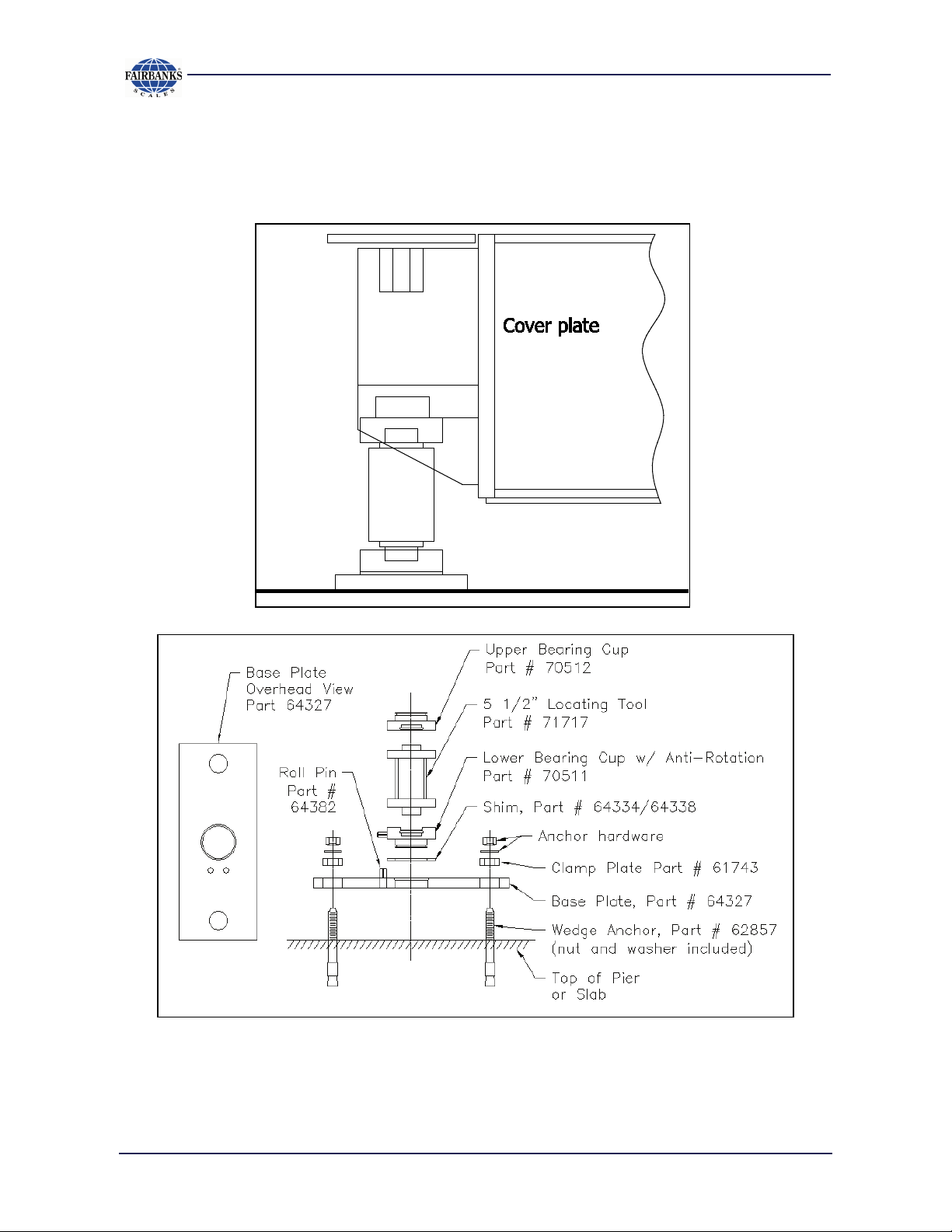
C. Determine if product is cover plated model or
undermount model.
The profile of the cover plated model has unique details and looks like this.
COVER PLATE MODEL – Locating tool detail
04/11 12 51255 Rev. 2
51255-1
 Loading...