

Page 1
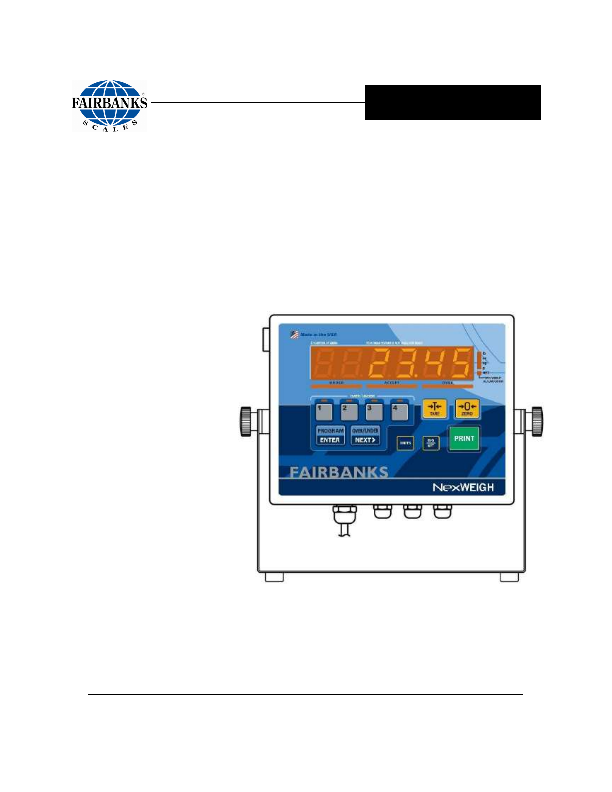
Operator’s Manual
NexWeigh
Weight Instrument
51216
© 2009 - 2014 by Fairbanks Scales, Inc.
All rights reserved
Revision 6 -- 04/14
Page 2

Page 3

Amendment Record
NEXWEIGH INSTRUMENT
Document 51216
Manufactured by Fairbanks Scales Inc.
821 Locust
Kansas City, Missouri 64106
Created 06/09 Created Document
Revision 1 06/09 Released Manual
Revision 2 07/09 Corrected Accumulate data string
Revision 3 03/10 Clarified security level and conversion factor.
Revision 4 03/11 Added serial data strings and serial commands and definitions
Revision 5 10/11 Added newest model information, with Ethernet Servers.
Revision 6 04/14 Added LED table and images and Data Output appendix.
04/14 3 51216 -- Rev. 6
Page 4

Disclaimer
Every effort has been made to provide complete and accurate information in this manual. However,
although this manual may include a specifically identified warranty notice for the product, Fairbanks
Scales makes no representations or warranties with respect to the contents of this manual, and reserves
the right to make changes to this manual without notice when and as improvements are made.
Fairbanks Scales shall not be liable for any loss, damage, cost of repairs, incidental or consequential
damages of any kind, whether or not based on express or implied warranty, contract, negligence, or
strict liability arising in connection with the design, development, installation, or use the scale.
© Copyright 2009 - 2014
This document contains proprietary information protected by copyright. All rights are reserved; no part
of this manual may be reproduced, copied, translated or transmitted in any form or by any means
without prior written permission of the manufacturer.
04/14 4 51216 -- Rev. 6
Page 5

Table of Contents
SECTION 1: GENERAL INFORMATION .................................................................. 7
1.1. Introduction .............................................................................................................. 7
1.2. Specifications .......................................................................................................... 8
1.3. Ethernet Specificications ........................................................................................ 9
SECTION 2: SERVICE POLICY INFORMATION ..................................................... 10
2.1. General Service Policy .......................................................................................... 10
2.2. Conferring with Our Client .................................................................................... 11
2.2.1. Service Technician’s Responsibilities ................................................................................ 12
2.2.2. Users’ Responsibility ......................................................................................................... 12
SECTION 3: INSTALLATION ................................................................................... 13
3.1. Prior to installation ................................................................................................ 13
3.1.1. Pre-Installation Checklist ................................................................................................... 13
3.1.2. Unpacking .......................................................................................................................... 14
3.1.3. Finding the Best Location .................................................................................................. 14
3.2. Mounting and Wiring the Instrument .................................................................... 16
3.2.1. Basic Installation Steps ...................................................................................................... 16
3.2.2. Connecting to the Load Cells............................................................................................. 17
3.2.3. Remote switches ............................................................................................................... 18
3.2.4. Powering Up the Instrument .............................................................................................. 18
SECTION 4: PROGRAMMING CONFIGURATION .................................................. 19
4.1. Overall Steps .......................................................................................................... 19
4.2. Introduction ............................................................................................................ 19
4.3. Keypad functions, Programming Mode. ............................................................... 20
4.4. Menu Access .......................................................................................................... 20
4.5. Programming Steps ............................................................................................... 21
4.5.1. Setup Menu........................................................................................................................ 21
4.5.2. Configuration Menu ........................................................................................................... 25
4.5.3. APP Menu .......................................................................................................................... 31
4.5.4. 4-20mA output setup ......................................................................................................... 33
SECTION 5: SERIAL I/O .......................................................................................... 34
5.1. Introduction ............................................................................................................ 34
5.2. Connections ........................................................................................................... 34
5.3. Print Data Strings ................................................................................................... 35
5.4. Printers ................................................................................................................... 36
5.4.1. 3550 Tape Printer .............................................................................................................. 36
5.4.2. TM-U295 Ticket Printer ...................................................................................................... 37
5.4.3. TM-U590 Ticket Printer ...................................................................................................... 38
5.4.4. Okidata 186T Form Printer ................................................................................................ 39
5.4.5. Okidata 420 Form Printer .................................................................................................. 43
5.4.6. Remote display .................................................................................................................. 46
5.4.7. Computer output ................................................................................................................ 46
5.4.8. NexWeigh Serial Commands and Definitions .................................................................... 47
04/14 5 51216 -- Rev. 6
Page 6

Table of Contents
5.5. Configuring the Ethernet Interface ....................................................................... 57
5.5.1. Obtaining the Fixed IP Address ......................................................................................... 57
5.5.2. Connecting the Unit ........................................................................................................... 57
5.5.3. Installing the DeviceInstaller GUI ...................................................................................... 57
5.5.4. Assigning an IP Address and Network Class .................................................................... 58
5.5.5. Adding the Unit to the Device List ..................................................................................... 59
5.5.6. Configuration ..................................................................................................................... 60
5.5.7. LEDs / Troubleshooting ..................................................................................................... 60
5.5.8. Device Server COM Port Settings ..................................................................................... 62
SECTION 6: OPERATIONS ..................................................................................... 63
6.1. Basic Scale Operations ......................................................................................... 63
6.2. Keypad Functions, Weigh mode ........................................................................... 63
6.3. Instrument Weighing Functions............................................................................ 64
6.3.1. Basic Weighing .................................................................................................................. 64
6.3.2. Gross Weighing ................................................................................................................. 64
6.3.3. Net Weighing ..................................................................................................................... 64
6.3.4. Gross/Tare/Net Weighing .................................................................................................. 64
6.3.5. Weight Accumulation ......................................................................................................... 65
6.3.6. Peak Hold Weighing .......................................................................................................... 69
6.3.7. Check Weighing ................................................................................................................ 70
6.3.8. Check Weigh Mode Operation.......................................................................................... 73
SECTION 7: SCALE MAINTENANCE ..................................................................... 74
7.1. Expanded Display Mode. ....................................................................................... 74
7.2. Scale Maintenance ................................................................................................. 74
7.2.1. Cleaning the Scale and Instrument ................................................................................... 74
APPENDIX I: KEYPAD REFERENCE ...................................................................... 75
APPENDIX II: ECOLAB INSTRUMENT SANITATION ............................................ 76
A. Safety Precautions ................................................................................................... 76
B. Sanitation Procedures ............................................................................................. 76
B. Sanitation Procedures, Continued .......................................................................... 77
APPENDIX III: DATA OUTPUT STRINGS ............................................................... 78
A. Poll Mode: ................................................................................................................. 78
B. Continuous Mode: .................................................................................................... 79
04/14 6 51216 -- Rev. 6
Page 7
Section 1: General Information
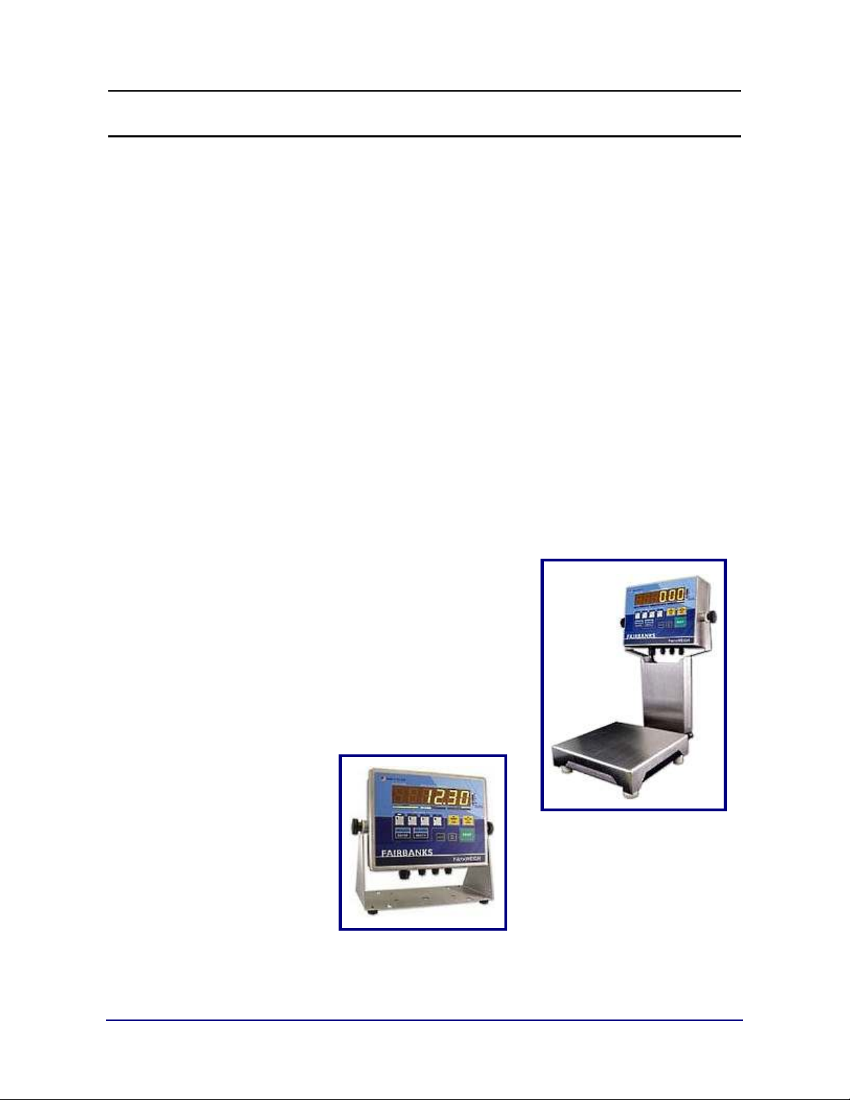
1.1. INTRODUCTION
The
NexWeigh Series Instrument
purpose use.
•
Designed for wash down environments.
•
The Instrument has a capacity setting of up to six digits.
•
Six (6) digit amber LED display.
•
120/240 VAC selectable.
•
Checkweigh Mode capable of storing four (4) different Checkweigh recipes.
•
Annunciators include
Accumulation.
Net Weight, Units, Under, Accept, Over
is designed for light capacity, general
, and
•
RS232 or RS485 Bidirectional Serial Communications Port.
•
Optional 4-20 mA Analog Interface available.
04/14 7 51216 -- Rev. 6
Page 8

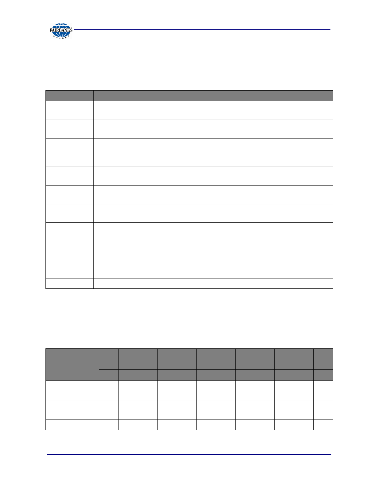
1.2. SPECIFICATIONS
FEATURE DESCRIPTION
Section1: General Information
Display
Display Update Rate
Capacity
Resolution
Division Sizes
Load Cell
Electrical
Excitation Voltage
Dimensions
Environment
Interfaces
Units
••••
1.25” Segmented LED.
─
12 amber segments for under-weighments.
─
12 green segments for correct weighments.
─
12 red segments for over-weighments.
••••
.1 – 1.0 second, selectable
••••
Up to 999990 programmable
••••
10,000 divisions, commercial.
••••
100,000 divisions, non-commercial.
••••
8,000,000 divisions, internal.
••••
.0001 – 50, selectable.
••••
Up to four (4) 350 ohm cells.
─
29937
─
30718 (IP69K)
••••
120 VAC or 240 VAC, selectable.
••••
5 VDC (sense leads required)
••••
9.8” x 7.6” x 3.3”
••••
NEMA 4X wash-down
••••
IP69K heavy wash-down
••••
RS232 or RS485 for bi-directional communication
••••
4-20mA Analog Output
••••
lbs, oz, kg, g and lbs/oz, or custom
─
31530 (without stand)
─
31531 (IP69K without stand)
Instrument Approvals
••••
CC: 09-024
••••
MC: AM-5725
••••
ETL: ETL Listed
─ Conforms to ANSI/UL STD 60950-1
••••
Certified to CAN/CSA C22.2 STD NO. 60950-1-03
04/14 8 51216 -- Rev. 6
Page 9

1.3. ETHERNET SPECIFICICATIONS
Section1: General Information
FEATURE
Models with
Ethernet
Interface
Software selectable Ethernet speed 10/100/Auto
Software selectable Half/Full/Auto duplex
Connector
Standards
DESCRIPTION
29937
31530
10Base-T/100BaseTX Ethernet port
RJ45
ARP, UDP, TCP, ICMP, Telnet, TFT, AutoIP, DHCP, HTTP, SNMP
TCP, UDP, and Telnet, TFTP
Indicators (LED)
Power
CPU Processor
Memory
Management
Operating
Temperature
Storage
Temperature
Serial Port
Power Input
10/100 Link/Activity – Green
Diagnostics – Red
Lantronix DSTNI-EX 48 MHz clock
256 KB zero wait state SRAM, 2 MB Flash
Lantronix Device Installer GUI, Serial login, SNMP, Telnet login, HTTP
-40° to 70° C (-40° 158° F)
-40° to 78° C (-40° 185° F)
15 KV ESD protection on RS232 and RS422/485 transceivers
Up to non-repeated 600 W 10/100 µsec pulse protection against
transient over voltages.
Ethernet Port
1500 VAC isolation shield with shield connected to chassis ground for
signal integrity and ESD protection.
30718 (IP69K)
100/100 Link/Activity – Green
Status – Green
31531 (IP69K)
04/14 9 51216 -- Rev. 6
Page 10
Section 2: Service Policy Information
2.1. GENERAL SERVICE POLICY
Prior to installation, always verify that
the equipment satisfies the customer's
requirements as supplied, and as
described in this manual.
If the equipment cannot satisfy the application and the application cannot be
modified to meet the design parameters of the equipment,
should NOT be attempted.
the installation
It is
the customer/operator's responsibility
to ensure the
equipment provided by Fairbanks is operated within the parameters
of the equipment's specifications and protected from accidental or
malicious damage.
Absolutely NO physical, electrical or program modifications other
than selection of standard options and accessories can be made
by customers to this equipment
Repairs are performed by Fairbanks Scales Service Technicians
and Authorized Distributor Personnel ONLY!
Failure to comply with this policy voids all implied and/or written
warranties.
W A R N I N G !
04/14 10 51216 -- Rev. 6
Page 11

Section 2: Service Policy Information
2.2. CONFERRING WITH OUR CLIENT
•
The technician must be prepared to recommend the arrangement of components which
provide the most efficient layout, utilizing the equipment to the best possible advantage.
•
Explain and review the warranty policy with the customer.
The
installing technician
fully trained and familiar with the equipment's capabilities and
limitations before the installation is considered complete.
•
All electrical assemblies must be returned intact for replacement credit using the
standard procedures.
•
At the time of installation, all electronic and mechanical adjustments are
considered to be part of the installation, and are included in the installation
charge(s).
is responsible that all personnel are
•
The AC receptacle/outlet shall be located near the Instrument and easily
accessible.
•
Electrical connections other than those specified may not be performed.
04/14 11 51216 -- Rev. 6
Page 12
Section 2: Service Policy Information
2.2.1. Service Technician’s Responsibilities
•
All electronic and mechanical calibrations and/or
adjustments required for making this equipment
perform to accuracy and operational specifications are
considered to be part of the installation.
─ They are included in the installation charge.
─ Only those charges which are incurred as a result
of the equipment's inability to be adjusted or
calibrated to performance specifications may be
charged to warranty.
•
The equipment consists of printed circuit assemblies which must be handled
using ESD handling procedures, and must be replaced as units.
─ Replacement of individual components is not allowed.
─ The assemblies must be properly packaged in ESD protective material and
returned intact for replacement credit per normal procedures.
2.2.2. Users’ Responsibility
Absolutely no physical, electrical or program modifications other
than selection of standard options and accessories are to be
made to this equipment.
04/14 12 51216 -- Rev. 6
Page 13

Section 3: Installation
3.1. PRIOR TO INSTALLATION
1. Review the pre-Installation checklist.
2. Speak with the customer, outlining all the installation details.
3. Unpack and check all component contents.
4. Find best location for each component, referring to the site instructions.
3.1.1. Pre-Installation Checklist
The following points should be checked and discussed with the Area Sales
Manager and/or customer, if necessary, before the technician goes to the site
and installs the equipment.
Check the customer's application to make certain it is within the capabilities and
design parameters of the equipment.
If the installation process might disrupt normal business operations, tell the
customer and ask that they make ample arrangements.
Be sure that the equipment operator(s) are available for
training.
The service technician reviews the recommended setup with
the Area Sales Manager or Area Service Manager, and
together they identify all necessary variations to satisfy the
customer's particular application.
04/14 13 51216 -- Rev. 6
Page 14

Section 3: Installation
3.1.2. Unpacking
Follow these guidelines when unpacking all equipment:
•
Check in all components and accessories according to the customer's order.
•
Remove all components from their packing material, checking against the invoice
that they are accounted for and not damaged.
─ Advise the shipper immediately, if damage has occurred.
─ Order any parts necessary to replace those which have been
damaged.
─ Keep the shipping container and packing material for future use.
Check the packing list.
•
Collect all necessary installation manuals for the equipment
and accessories.
•
Open the equipment and perform an inspection, making certain
that all hardware, electrical connections and printed circuit
assemblies are secure.
•
Do not reinstall the cover if the final installation is to be performed after the preinstallation checkout.
3.1.3. Finding the Best Location
Position the equipment with these points in mind:
•
Intense direct sunlight can harm the display.
•
Do not locate near magnetic material or equipment/Instruments which use
magnets in their design.
•
Avoid areas which have extreme variations in room temperatures. Temperatures
outside the Instrument’s specifications will affect the weighing accuracy of this
product.
•
Do not open the Instrument if there is any evidence of damage to it or any other
scale component or supporting structure.
•
When selecting the right location for the Instrument and the scale, keep the
components completely away from all high water, such as low-lying areas that
may flood, and away from any drain pipes.
04/14 14 51216 -- Rev. 6
Page 15
Section 3: Installation
IMPORTANT INSTALLATION NOTICE
•
All load cells, load cell cables and interconnecting cables used to connect all
scale components shall be located
distance away
electric current carrying conductors.
•
This includes digital weight instruments, junction boxes,
sectional controllers, and power supplies.
•
This includes any peripheral devices, such as printers, remote
displays, relay boxes, remote terminals, card readers, and
auxiliary data entry devices.
•
Also included is the scale components themselves, such as
120 volt AC, 240 volt AC, 480 volt AC and electric supply of
higher voltage wiring runs and stations, AC power transformers,
overhead or buried cables, electric distribution panels, electric
motors, florescent and high intensity lighting which utilize
ballast assemblies, electric heating equipment, traffic light
wiring and power, and relay boxes.
from all single and multiple phase high energy circuits and
a minimum of thirty-six (36”) inches
•
All scale components, including digital weight instruments and
peripheral devices are not designed to operate on internal
combustion engine driven electric generators and other similar equipment.
Electric arc welding
can severely damage scale
components such as digital weight instruments, junction
boxes, sectional controllers, power supplies, and load cells.
NOTE:
For additional information, please contact your
Fairbanks Scales
Service Representative.
04/14 15 51216 -- Rev. 6
Page 16
C A U T I O N
3.2. MOUNTING AND WIRING THE INSTRUMENT
3.2.1. Basic Installation Steps
The NexWeigh Instruments arrive fully assembled.
Section 3: Installation
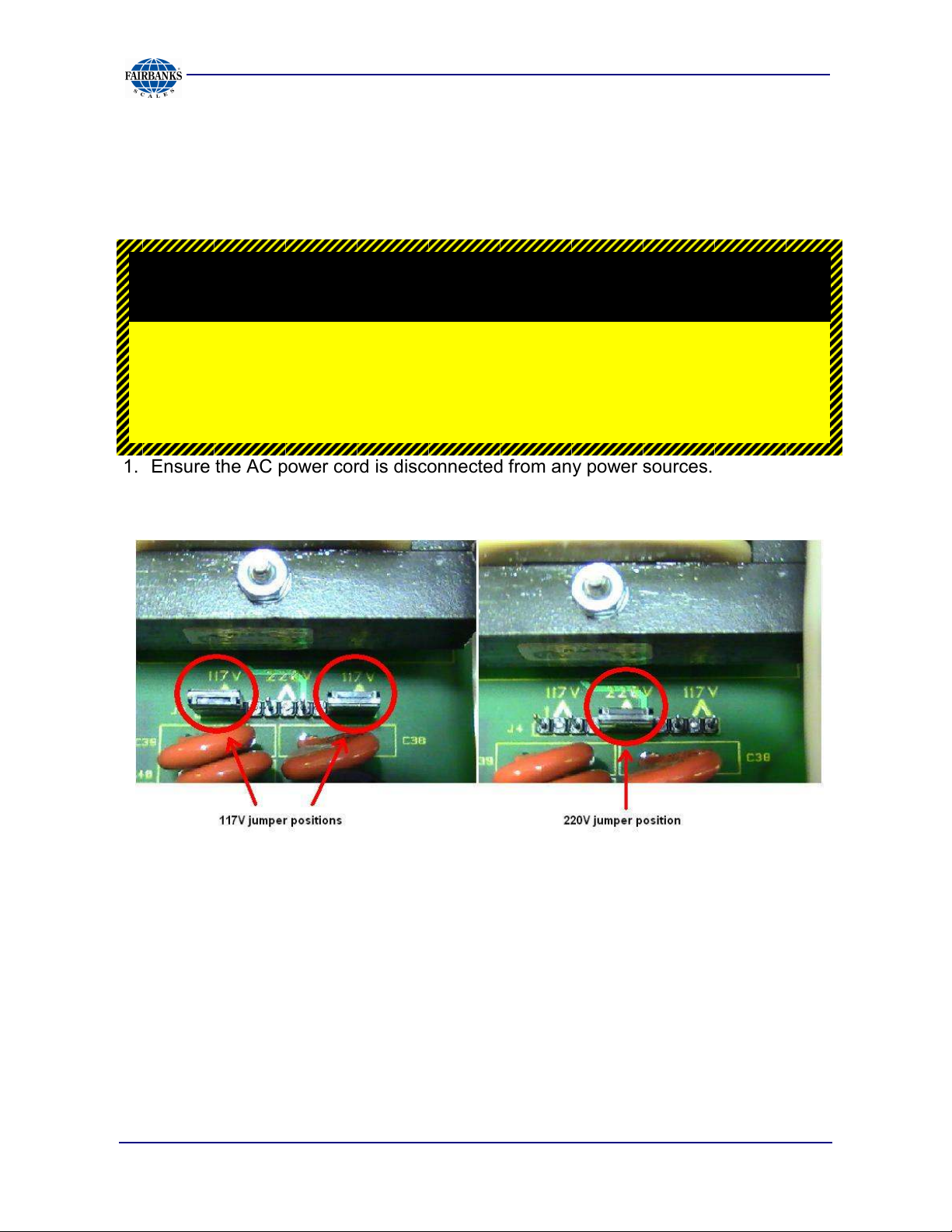
For 220 to 240 VAC operations, change the setting as shown
1. Ensure the AC power cord is disconnected from any power sources.
2. Remove the cover and place the unit face down on a bench.
3. On the main PC board, locate the jumpers at J4
The Factory Default Setting for the NexWeigh is
110 to 120 VAC operation.
below before powering up the unit.
4. Remove the jumpers from the 117V positions and replace one of them on the
220V position as shown.
5. Remove the 120 VAC plug from the end of the power cord and attach a proper
220-240 VAC plug. Connect the green wire and the shield to the ground lug.
Please note, original wiring connects brown to AC hot and blue to neutral.
6. Reattach all cables and replace the front cover assembly.
Caution: Improper connections at J4 can cause
catastrophic damage to the instrument
04/14 16 51216 -- Rev. 6
Page 17
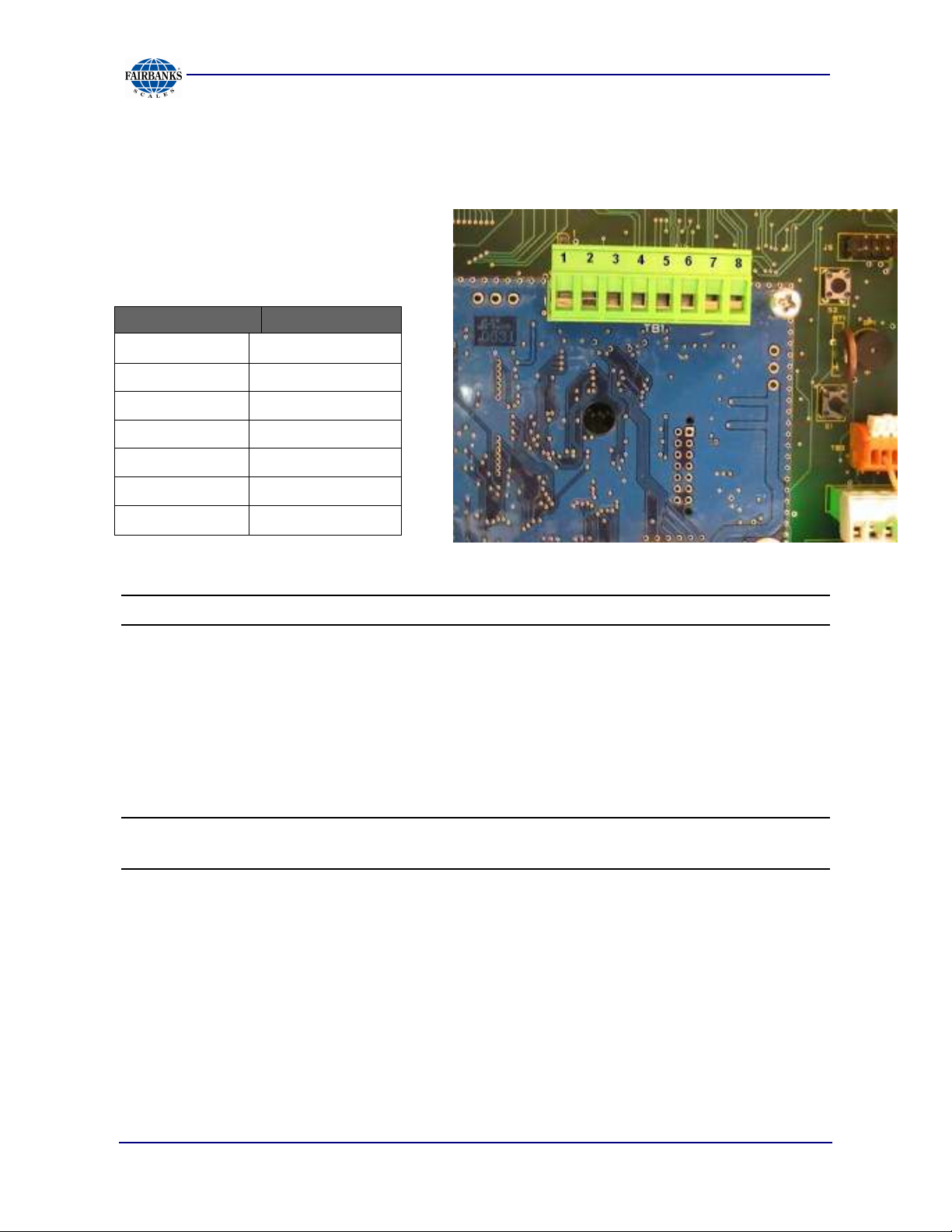
3.2.2. Connecting to the Load Cells
Connect the platform interface cable
wires to the terminal strip TB1 on the
Small Block PCB as follows:
TB1 Pin no. FUNCTION
Section 3: Installation
1
2 (+) Excitation
3 (+) Sense
4 (-) Sense
6 Shield
7 (+) Signal
8
Note:
Note: There are no internal sense jumpers provided. Jumpers must be installed from
+Excitation to +Sense and from –Excitation to –Sense if no sense leads are used.
Reassemble housing and proceed with installation.
(−) Excitation
(−) Signal
Pin numbers added for clarity.
NOTE:
wiring color code.
04/14 17 51216 -- Rev. 6
Refer to the appropriate Platform Service Manual for the proper interface
Page 18
Section 3: Installation
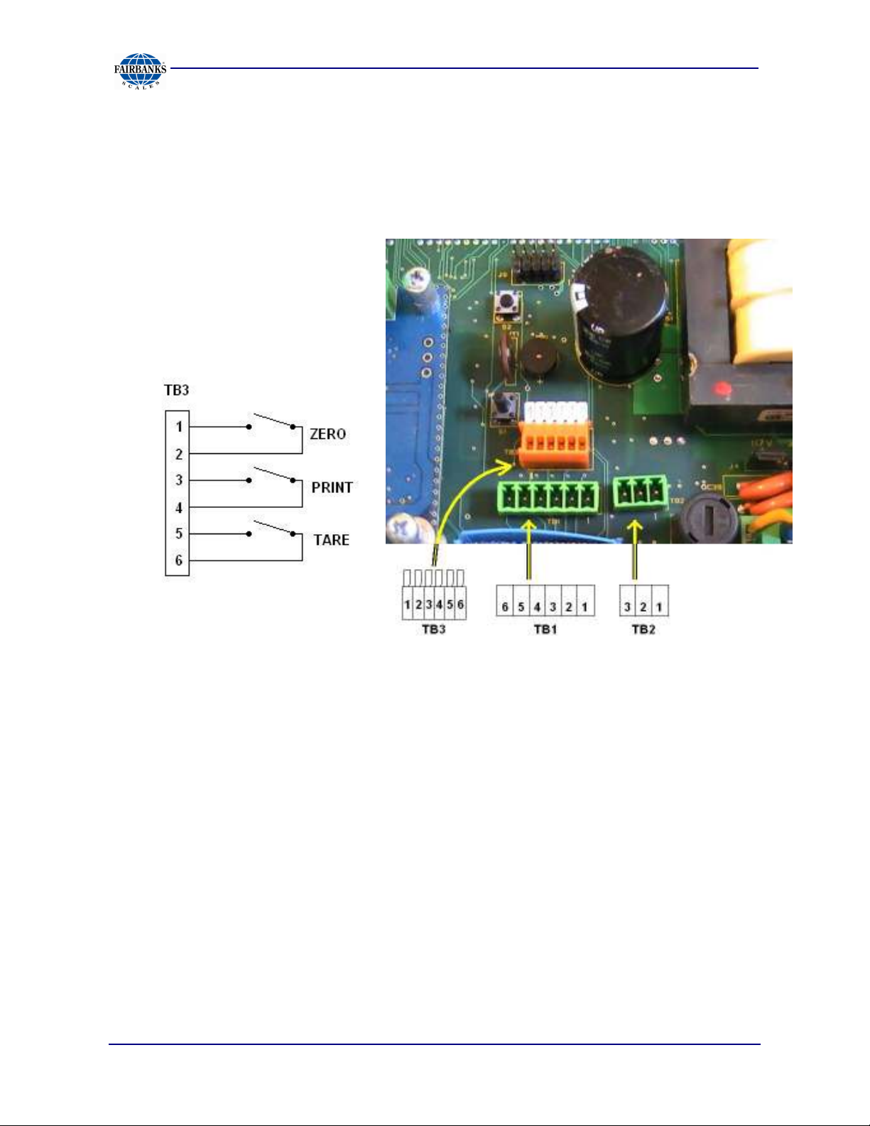
3.2.3. Remote switches
The NexWeigh has three available remote switch inputs. A dry contact normally open
switch can be mounted and operated remotely using the connections on TB3.
3.2.4. Powering Up the Instrument
The Instrument performs a warm-up cycle.
•
The Instrument initiates a test, displaying numbers
•
The Program number and Revision Information displays.
•
The Instrument then displays the current weight on the scale
to
8888
, and lights up all LED’s.
04/14 18 51216 -- Rev. 6
Page 19

Section 4: Programming Configuration
4.1. OVERALL STEPS
Follow these steps to program the NexWeigh Instrument.
A. Configure the NexWeigh Instrument operating parameters.
B. Calibrate the NexWeigh Instrument.
C. Set up the NexWeigh Instrument options.
4.2. INTRODUCTION
•
The program group is shown and accessed in steps.
•
Each program group may be entered and modified, or skipped to the next group.
•
At each step, a word or abbreviation displays, indicating the parameter to be set.
•
Each step then may be viewed or modified.
•
At the end of programming a SAvE prompt will be displayed.
•
Press
changes made.
The following is a rendering of the four programming groups. Pressing
OVER/UNDER/NEXT
PROGRAM/ENTER
in Sec 4.3 for full details of front panel pushbuttons for programming mode.
SEtuP ConFiG APP CAL donE
SAvE CAncEL
PROGRAM/ENTER
or
TARE
will enter the program steps in a particular group. See chart
to SAvE and exit or scroll to CAncEL to disregard
will scroll through the choices listed.
04/14 19 51216 -- Rev. 6
Page 20
Section 4: Programming Configuration
4.3. KEYPAD FUNCTIONS, PROGRAMMING MODE.
This chart shows what action will be taken when a front panel key is pressed in the
programming mode.
KEY ACTION
1
2
3
4
TARE
ZERO Accepts the displayed value and advances to the next program step like ENTER.
PROGRAM
ENTER
OVER/UNDER
NEXT
UNITS
B/G
NET
PRINT
No function in programming mode.
•••• Exception, decrements selected digit when entering numeric data.
No function in programming mode.
•••• Exception exits to done prompt when entering numeric data.
No function in programming mode.
•••• Exception, moves flashing digit to far left position when entering numeric data.
No function in programming mode.
Scrolls backwards through the choices for each program step.
•••• Exception, moves flashing digit left when entering numeric data.
•••• Exception, resets all digits to zeroes when entering numeric data.
Accepts the displayed value and advances to the next program step.
Scrolls forward through the choices for each program step.
•••• Exception, moves flashing digit right when entering numeric data.
Scrolls forward through the choices for each program step
•••• Exception, increments digit when entering numeric data.
Scrolls backward through programming steps.
•••• Returns to the Weigh Mode after multiple pressings.
No function in programming mode. Scrolls decimal point to the right in CAL mode.
4.4. MENU ACCESS
This chart shows which menus can be accessed from the front panel based on the
security level setting and the internal jumper (JP1) position.
SL0 SL0 SL1 SL1 SL2 SL2 SL3 SL3 SL4 SL4 SL5 SL5
MENU JP1 JP1 JP1 JP1 JP1 JP1 JP1 JP1 JP1 JP1 JP1 JP1
Out In Out In Out In Out In Out In Out In
SEtUP
ConFiG
APP
CAL
ChEc / HoLd
04/14 20 51216 -- Rev. 6
Y Y Y Y Y Y Y Y N N N N
Y
N Y N Y N N N N N N N
Y Y Y Y Y Y Y Y N N N N
Y N Y N N N N N N N N N
Y N Y N Y N N N N N N N
Page 21

4.5. PROGRAMMING STEPS
4.5.1. Setup Menu
Section 4: Programming Configuration
1. Press and hold the
display SEtuP.
2. Press the
3. Press
The following section defines the program settings for the NexWeigh Instrument. The
default selections are underlined.
PROGRAM/ENTER
ZERO
to set the desired Programming Menu.
PROGRAM/ENTER
key to enter setup mode.
key or press S1 on the main PCB to
Programming Time Format: This will determine whether the clock is
displayed and printed in 24 hour (military) or 12 hour (AM/PM) format. The display
will indicate either
to change the selection. Press
12hour
or
24hour
. Press
PROGRAM/ENTER
OVER/UNDER/NEXT
to enter the selection.
or
TARE
SEt-ti: Programming the Time: Time is set as
in military format. The display will indicate
the 10s digit of the hour flashing. Press
to decrease the digit. Press
or press
TARE
to move the flashing digit left. When the time is correct, press
PROGRAM/ENTER
OVER/UNDER/NEXT
to accept the time and go to the next step.
SEt-ti
UNITS
HH.MM.SS
followed by the current time with
to increase the digit or the 1 button
to move the flashing digit right
and must be entered
SEt-dA: Programming the date: Date is set as MM.DD.YY format. The display
will indicate
flashing. Press
Press
move the flashing digit left. When the date is correct, press
to accept the date and go to the next step.
OVER/UNDER/NEXT
Id: Scale ID: This step sets the scale ID from
XX
where XX is the current ID setting. Press
to increase the setting, or press
is displayed, press
04/14 21 51216 -- Rev. 6
SEt-dA
UNITS
PROGRAM/ENTER
followed by the current date with the 10s digit of the month
to increase the digit or the 1 button to decrease the digit.
to move the flashing digit right or press
TARE
to
PROGRAM/ENTER
1-32
. The display will indicate
TARE
OVER/UNDER/NEXT
to decrease the setting. When the correct ID
to enter the value. The default Id is 01.
or
UNITS
Id
Page 22

4.5.1. Setup Menu, Continued
Section 4: Programming Configuration
Port 1: Programming Port 1: The display will indicate
the current setting. Press
through the available choices. Press
selection. Available selections are listed below.
OFF
PoLL
PoLLid
Contin
button
Auto
diS
*
Underline identifies the program default
Function is not active.
Computer demand mode.
Computer demand mode with ID
Continuous output.
Transmit when
Transmit occurs when
Continuous output using remote display format.
OVER/UNDER/NEXT, UNITS
PROGRAM/ENTER
PRINT
is pressed.
Autoprint
threshold is met or exceeded.
Port 1,
then
or
TARE
to enter the correct
bAud: Programming Port 1 baud rate: The display will indicate
current setting. Press
scroll down through the available choices. Press
selection. Available selections are:
OVER/UNDER/NEXT
or
UNITS
to scroll up, or
PROGRAM/ENTER
OutPut
to scroll
bAud
, then
then the
TARE
to enter the
to
300
600
9600
19200
dbit: Programming Port 1 data bits: The display will indicate
either 7 or 8. Press
value. Press
PROGRAM/ENTER
P: Programming Port 1 Parity setting: The display will indicate
setting. Press
Press
PROGRAM/ENTER
OVER/UNDER/NEXT, UNITS
1200
38400
2400
57600
OVER/UNDER/NEXT
to enter proper selection.
to enter the selection. Available selections are:
,
UNITS
or
4800
115200
, or
TARE
dbit X
TARE
to change the selection.
to select proper
P
along with the current
P nonE P odd P EvEn
buSY: Programming Port 1 handshaking: The display will indicate
where XX is either no, Lo, or Hi. Press
TARE
to change the selection. Press
OVER/UNDER/NEXT, UNITS
PROGRAM/ENTER
to enter the selection.
where X is
XXbuSY
or
,
04/14 22 51216 -- Rev. 6
Page 23

Section 4: Programming Configuration
4.5.1. Setup Menu, Continued
oPti: Include time data with transmitted data: This determines whether or not to
include the time in the data string for Port 1. Display will indicate
the current selection of Y for yes to include, or n for no to exclude. Press
OVER/UNDER/NEXT, UNITS
PROGRAM/ENTER
to enter the selection.
or
TARE
to change the selection. Press
oPti
followed by
oPdA: Include date data with transmitted data: This determines whether or not to
include the date in the data string for Port 1. Display will indicate
the current selection of Y for yes to include, or n for no to exclude. Press
OVER/UNDER/NEXT, UNITS
PROGRAM/ENTER
to enter the selection.
or
TARE
to change the selection. Press
oPdA
followed by
oPId: Include ID data with transmitted data: This determines whether or not to
include the ID in the data string for Port 1. Display will indicate
current selection of Y for yes to include, or N for no to exclude. Press
OVER/UNDER/NEXT, UNITS
PROGRAM/ENTER
to enter the selection.
or
TARE
to change the selection. Press
oPId
followed by the
Port 2: Programming Port 2: The display will indicate
the current setting. Press
through the available choices. Press
selection. Available selections are listed below.
OFF
PoLL
PoLLid
*
Underline identifies the program default
NOTE:
Function is not active.
Computer demand mode.
Computer demand mode with ID
If
B/G / NET
OVER/UNDER/NEXT, UNITS
PROGRAM/ENTER
is pressed after Port 2, the instrument will revert back to ID.
Port 2
, then
or
TARE
to enter the correct
OutPut,
to scroll
then
04/14 23 51216 -- Rev. 6
Page 24

4.5.1. Setup Menu, Continued
Section 4: Programming Configuration
bAud: Programming Port 2 baud rate: The display will indicate
current setting. Press
scroll down through the available choices. Press
selection. Available selections are:
300 600 1200 2400 4800
9600 19200 38400 57600 115200
dbit: Programming Port 2 data bits: The display will indicate
either 7 or 8. Press
value. Press
PROGRAM/ENTER
P: Programming Port 2 Parity setting: The display will indicate
setting. Press
Press
PROGRAM/ENTER
P nonE P odd P EvEn
OVER/UNDER/NEXT, UNITS
OVER/UNDER/NEXT
or
UNITS
PROGRAM/ENTER
OVER/UNDER/NEXT, UNITS
to enter proper selection.
or
TARE
to enter the selection. Available selections are:
to scroll up, or
dbit X
, or
TARE
P
along with the current
to change the selection.
bAud
then the
TARE
to enter the
where X is
to select proper
to
oPti: Include time data with transmitted data: This determines whether or not to
include the time in the data string for Port 2. Display will indicate
the current selection of Y for yes to include, or n for no to exclude. Press
OVER/UNDER/NEXT, UNITS
PROGRAM/ENTER
to enter the selection.
or
TARE
to change the selection. Press
oPti
followed by
oPdA: Include date data with transmitted data: This determines whether or not to
include the date in the data string for Port 2. Display will indicate
the current selection of Y for yes to include, or n for no to exclude. Press
OVER/UNDER/NEXT, UNITS
PROGRAM/ENTER
to enter the selection.
or
TARE
to change the selection. Press
oPdA
followed by
oPId: Include ID data with transmitted data: This determines whether or not to
include the ID in the data string for Port 2. Display will indicate
current selection of Y for yes to include, or n for no to exclude. Press
OVER/UNDER/NEXT, UNITS
PROGRAM/ENTER
to enter the selection.
or
TARE
to change the selection. Press
oPId
followed by the
04/14 24 51216 -- Rev. 6
Page 25

Section 4: Programming Configuration
4.5.1. Setup Menu, Continued
Int: Display brightness setting: This changes the intensity of the display brightness.
The display will indicate Int followed by the intensity setting from
the brightest. Press
scroll down through the available choices. Press
selection. The default setting is 4.
The NexWeigh instrument will return to the
menu heading to continue programming, or select
OVER/UNDER/NEXT
SEtuP
or
UNITS
to scroll up, or
PROGRAM/ENTER
prompt. Navigate to the desired
Done
to finish.
1-7
, with 7 being
TARE
to enter the
to
4.5.2. Configuration Menu
4. Press and hold the
display
5. Press UNITS or OVER/UNDER/NEXT to display ConFiG.
6. Press the
SEtUP
PROGRAM/ENTER
PROGRAM/ENTER
.
key to enter setup menu.
key or press S1 on the main PCB to
CAP: Programming the scale capacity: The display will indicate
the current setting with the most significant digit blinking. Press
or the 1 to scroll down to the desired numeric value. The
key will move the flashing digit to the right, and the
Press
NOTE:
PROGRAM/ENTER
Capacity can be up to six (6) displayed digits.
when the display shows the correct capacity setting.
TARE
OVER/UNDER/NEXT
key will move it left.
UNITS
CAP
followed by
to scroll up,
04/14 25 51216 -- Rev. 6
Page 26

4.5.2. Configuration Menu, Continued
Section 4: Programming Configuration
UnitS: Programming the scale units: The display will indicate
current setting by displaying a lit LED symbol next to the printed unit legend beside
the display. Press
the possible choices. Press
selections are:
OVER/UNDER/NEXT, UNITS
PROGRAM/ENTER
to enter the selection. Available
or
TARE
UnitS
to scroll through all
, and the
lb/oz/kg/g lb/oz/kg lb/oz/g lb/oz
lb/kg/g lb/kg lb/g lb
oz/kg/g oz/kg oz/g oz
kg/g kg g
NOTES:
The
the NEXWEIGH.
lb-oz
and
custom unit settings
cannot be used as the Primary Unit in
The
lb-oz
and
custom unit settings
are not legal for trade.
P-Unit: Programming the primary unit: (the unit that the instrument will default to
upon power up) The display will indicate
displaying the lit LED next to the printed unit legend beside the display. Press
OVER/UNDER/NEXT, UNITS
change to indicate the selection. Press
Available selections are:
or
lb g kg oz
NOTE:
Selection availability is dependent upon the programmed
P-Unit
TARE
and indicate the current setting by
while observing the LED which will
PROGRAM/ENTER
to enter the selection.
UnitS
selection.
LboZ: pounds-ounces mode: The display will indicate LboZ and the current
selection, either Y for enable or N for disable. Press
UNITS
the selection.
or
TARE
to change the selection. Press
OVER/UNDER/NEXT
PROGRAM/ENTER
,
to enter
04/14 26 51216 -- Rev. 6
Page 27

Section 4: Programming Configuration
4.5.2. Configuration Menu, Continued
CuSt: Custom units. The display will indicate CuSt and the current selection,
either Y for enable or N for disable. Press
TARE
to change the selection. Press
OVER/UNDER/NEXT, UNITS
PROGRAM/ENTER
to enter the selection.
or
NOTE:
mode.
When custom units are active, units LED instruments are off in the weigh
AZt: Programming the Automatic Zero Tracking band: (this feature will maintain
zero when small amounts of material are placed on the scale, such as rain, snow,
debris, etc.) The display will indicate
OVER/UNDER/NEXT, UNITS
PROGRAM/ENTER
OFF
0.5
1
3
*
Underline identifies the program default.
Function is not active.
Half (½) of a division / increment / graduation.
One (1) division / increment / graduation.
Three (3) divisions / increments / graduations.
to enter the selection. Available selections are:
AZt X
or
TARE
where X is the current setting. Press
to change the selection. Press
bAL: Programming the motion band (the range in divisions/increments/graduations
that weight must be stable before a print, zero, or tare function will be allowed). The
display will indicate
OVER/UNDER/NEXT, UNITS
PROGRAM/ENTER
bAL X
where X is the current setting. Press
or
TARE
to enter the selection. Available selections are:
to change the selection. Press
OFF
0.5
1
3
*
Underline identifies the program default.
04/14 27 51216 -- Rev. 6
Function is not active.
Half (½) of a division / increment / graduation.
One (1) division / increment / graduation.
Three (3) divisions / increments / graduations.
Page 28

Section 4: Programming Configuration
4.5.2. Configuration Menu, Continued
O.r: Programming the zero range: (the percentage of scale capacity that may be
removed by pressing the Zero Key). The display will indicate
current setting. Press
selection. Press
are:
OVER/UNDER/NEXT, UNITS
PROGRAM/ENTER
to enter the selection. Available selections
100 100 percent zero range
2 2 percent zero range
or
O.r X
TARE
where X is the
to change the
d: Programming the division size: The display will indicate
current division size setting. Press
or
TARE
PROGRAM/ENTER
to scroll down through the available choices. Press
to enter the selection. Available selections are:
OVER/UNDER/NEXT
d
followed by the
or
UNITS
to scroll up,
50 20 10 5 2 1
0.5 0.2 0.1 0.05 0.02 0.01
0.005 0.002 0.001 0.0005 0.0002 0.0001
FiLtEr: Programming the filter setting: (intended to minimize the effects of
motion, vibration, and wind currents) The display will indicate
current filter setting. Press
TARE
to enter the selection. Available selections are:
to scroll down through the available choices. Press
OVER/UNDER/NEXT
or
UNITS
1 3 5 11 15 20 30 50
FiLtEr
followed by the
to scroll up, or
PROGRAM/ENTER
FLF: Flush filter factor: Allows instrument to switch to fast filter rate if weight
change exceeds the number of divisions in setting. The display will indicate
followed by the current setting. Press
up, or
PROGRAM/ENTER
TARE
to scroll down through the available choices. Press
to enter the selection. Available selections are:
OVER/UNDER/NEXT
or
UNITS
oFF 1 2 5 10 20 50 100
FLF
to scroll
04/14 28 51216 -- Rev. 6
Page 29

Section 4: Programming Configuration
4.5.2. Configuration Menu, Continued
tArE: Programming the tare setting: (the means by which a container’s weight
may be removed, to set the instrument to display the net weight only) The display
will indicate
OVER/UNDER/NEXT, UNITS
PROGRAM/ENTER
OFF
ON
On-CLr
*
Underline identifies the program default
tArE
followed by the current tare setting. Press
or
TARE
to enter the selection. Available selections are:
Tare is disabled.
Tare is active.
Tare automatically clears when Gross weight returns to Zero.
to change the selection. Press
HL: Overload limit: The actual value at which the display goes to
as a percentage of capacity). The display will indicate HL followed by the current
setting. Press
down through the available choices. Press
selection. Available selections are:
OVER/UNDER/NEXT
or
UNITS
to scroll up, or
PROGRAM/ENTER
OL
(represented
TARE
to enter the
to scroll
102.5 103 105 110 300
UL:
(represented as a percentage of capacity behind zero). The display will indicate UL
followed by the current setting. Press
up, or
PROGRAM/ENTER
U
nderload Limit: The actual value at which the display goes to UL
TARE
OVER/UNDER/NEXT
to scroll down through the available choices. Press
to enter the selection. Available selections are:
or
UNITS
to scroll
5.5 10 25 50 100
04/14 29 51216 -- Rev. 6
Page 30

Section 4: Programming Configuration
4.5.2. Configuration Menu, Continued
d rAtE: Programming the display update rate: The times between display
updates in seconds. The display will indicate
Press
through the available choices. Press
Available selections are:
OVER/UNDER/NEXT
or
UNITS
PROGRAM/ENTER
0.1 0.2 0.3 0.4 0.5 0.6 0.7 0.8
0.9 1.0
d rAtE
to scroll up, or
and then the current setting.
TARE
to scroll down
to enter the selection.
P1: Output format of Port1, GTN or net only: This determines whether the output
from Port1 will be transmitted as a net weight only or a gross/tare/net weighment.
The display will indicate P1 followed by the current setting. Press
OVER/UNDER/NEXT, UNITS
PROGRAM/ENTER
to enter the selection. Available choices are:
or
TARE
to change the selection. Press
Gtn nEt
P2: Output format of
output from Port2 will be transmitted as a net weight only or a gross/tare/net
weighment. The display will indicate P1 followed by the current setting. Press
OVER/UNDER/NEXT, UNITS
PROGRAM/ENTER
Gtn nEt
The NexWeigh instrument will now return to the
desired menu heading to continue programming, or to
Port2, GTN
to enter the selection. Available choices are:
or
or
TARE
net only
: This determines whether the
to change the selection. Press
ConFiG
prompt. Navigate to the
DONE
to finish.
04/14 30 51216 -- Rev. 6
Page 31

4.5.3. APP Menu
Section 4: Programming Configuration
7. Press and hold the
display
8. Press
9. Press the
SEtUP
UNITS
PROGRAM/ENTER
PROGRAM/ENTER
.
or
OVER/UNDER/NEXT
key to enter
key or press S1 on the main PCB to
twice to display
APP
menu.
APP
.
X.XXuPd: Display microvolts per division: This is a reference to display the
current microvolts per division. The display will indicate X.XXuPd where X.XX is a
numeric value of the microvolts per division. Press any front panel pushbutton other
than
B/G / NET
to continue.
4-20: 4-20mA analog output setting: Enables or disables the output. The display
will indicate 4-20 followed by the current setting of Y for enable and N for disable.
Press
PROGRAM/ENTER
OVER/UNDER/NEXT, UNITS
to enter the selection.
or
TARE
to change the selection. Press
ACC: Accumulate feature enabled: Enables or disables the accumulate feature.
The display will indicate
for disable. Press
selection. Press
PROGRAM/ENTER
ACC
followed by the current setting of Y for enable and N
OVER/UNDER/NEXT, UNITS
to enter the selection.
or
TARE
to change the
A thLd: Autoprint and accumulate threshold: This is the number of divisions the
instrument must meet or exceed for an autoprint or an auto-accumulation to occur.
The display will indicate
left digit flashing. Press
the flashing digit. Press
right or press the
the display shows the correct threshold setting. The acceptable range is 1 to 1000
and default value is 10 divisions.
TARE
A thld
UNITS
OVER/UNDER/NEXT
to move it to the left. Press
, followed by the current setting in divisions with the
to increase the digit, press the 1 key to decrease
to move the flashing digit to the
PROGRAM/ENTER
when
04/14 31 51216 -- Rev. 6
Page 32

Section 4: Programming Configuration
4.5.3. APP Menu, Continued
AOut: Autoprint and autoaccumulate output: This setting will determine whether
the instrument will autoprint during an automatic accumulation. This setting is only
active if port 1 is set to
AOut followed by a Y for enable or an n for disable. Press
OVER/UNDER/NEXT, UNITS
PROGRAM/ENTER
Auto
and accumulation is enabled. The display will indicate
or
TARE
to enter the selection.
to change the selection. Press
bEEP: Audible tone when key is pressed: This will enable or disable the audible
tone to acknowledge pressing a front panel key. The display will indicate
followed by a Y for enable or an n for disable. Press
UNITS
the selection.
or
TARE
to change the selection. Press
OVER/UNDER/NEXT
PROGRAM/ENTER
bEEP
,
to enter
C-FACt: Conversion factor for custom units: The primary units divided by this
value will determine the custom units if it is enabled. The display will indicate
FACt
digit, press the 1 key to decrease the flashing digit. Press
to move the flashing digit to the right or press the
PRINT
the display shows the correct conversion factor.
The default conversion factor is
Note: An example of custom units might be to display the weight in tons. In this case
the conversion factor is 2000.0 if the primary unit is lb.
The NexWeigh instrument will now return to the
desired menu heading to continue programming, or to
followed by a value with the left digit flashing. Press
TARE
to move the decimal point to the right. Press
8.3333
for gallons of water conversion.
APP
to move it to the left. Press
PROGRAM/ENTER
prompt. Navigate to the
Done
UNITS
to increase the
OVER/UNDER/NEXT
if finished.
C-
when
04/14 32 51216 -- Rev. 6
Page 33

Section 4: Programming Configuration
4.5.4. 4-20mA output setup
Introduction
The 4-20mA analog output is passive, so therefore it requires the receiving element
to supply the loop with a dedicated, isolated power source from 7-40V DC. The
output is linear throughout the range from 4mA to 20mA, and can be programmed to
increase (upweigh) or decrease (downweigh) as weight is increased.
Connections are as follows:
Pin 1 + 4-20mA
Pin 2 – 4-20mA
Press and hold the
followed by either
output will follow the gross or net weight. Press
OVER/UNDER/NEXT
select the desired mode. Press
the selected choice.
Instrument will now display
flashing, and the primary units LED lit for programming reference. This is the weight
at which the output will be 4mA. Please note that at this time the output will be forced
to 4mA to allow the user to verify that the receiving device is set properly.
Press
Press
TARE
Press
Instrument will now display
flashing, and the primary units LED lit for programming reference. This is the weight
at which the output will be
forced to 20mA to allow the user to verify that the receiving device is set properly.
UNITS
OVER/UNDER/NEXT
to move it to the left. Press
PROGRAM/ENTER
UNITS
GroSS
to increase the digit, press the 1 key to decrease the flashing digit.
key until the instrument displays
or
nEt
. This determines whether the
to toggle between the two choices and
PROGRAM/ENTER
4-20.Lo
when the display shows the desired weight value.
4-20.Hi
20mA
followed by a weight value with the left digit
to move the flashing digit to the right or press the
PRINT
followed by a weight value with the left digit
. Please note that at this time the output will be
to move the decimal point to the right.
4-20
to enter
Press
Press
TARE
Press
return to normal weighing.
04/14 33 51216 -- Rev. 6
UNITS
OVER/UNDER/NEXT
to move it to the left. Press
PROGRAM/ENTER
to increase the digit, press the 1 key to decrease the flashing digit.
to move the flashing digit to the right or press the
when the display shows the desired weight value to
PRINT
to move the decimal point to the right.
Page 34

Section 5: Serial I/O
5.1. INTRODUCTION
The NexWeigh Instrument is equipped with two (2) serial output ports. Port 1 is a
bidirectional RS232 port, and Port 2 is a bidirectional RS485 port. Port 1 can be
configured to operate with a variety of printers, computer applications, and remote
displays.
5.2. CONNECTIONS
TB1 Pin Port 1 designation
1 Chassis ground
2 Receive data (RX)
3 Transmit data (TX)
4 Clear to send (CTS)
5 Signal ground (GND)
6 Request to send (RTS)
TB2 Pin Port 2 designation
1 RS485+
2 RS485-
3 Signal ground
04/14 34 51216 -- Rev. 6
Page 35

5.3. PRINT DATA STRINGS
Serial Data String – Demand Mode:
Gross <WWWWWWW> <SP> <lb><SP><GR><CR><LF>
Then, (if applicable)
Tare <WWWWWWW> <SP> <lb><SP><TA><CR><LF>
Then, (if applicable)
Net <WWWWWWW> <SP> <lb><SP><NT><CR><LF>
Then, (if applicable)
Time <HH><:><MM><:><SS><SP><AM><CR><LF>
Then, (if applicable)
Date <MM></><DD></><YY><CR><LF>
Then, (if applicable)
ID <Scale><SP><Id><SP><##><CR><LF>
<CR><LF>
Section 5: Serial I/O
Serial Data String – Continuous Mode:
Gross (Stable) <WWWWWWW> <SP> <lb><SP><GR><CR><LF><EOT>
<WWWWWWW> Up to 6 places with no decimal, up to 7 places with a decimal point
<SP> Space
<lb> Unit of measure could be: lb, kg, gr, oz
<GR> or <gr> Upper case indicates stable weight, lower case unstable weight
<TA> Tare weight
<NT> or <nt> Net weight (upper case = stable, lower case = unstable)
<CR> Carriage return
<LF> Line feed
<EOT> End of text
Time HH = Hour, MM = Minute, SS = Seconds, and AM or PM
Date MM = Month, DD = Day, YY = last 2 digits of the year (20YY)
ID “Scale Id” and ## = 2 digits for the actual scale ID
04/14 35 51216 -- Rev. 6
Page 36

Section 5: Serial I/O
5.4. PRINTERS
5.4.1. 3550 Tape Printer
The NexWeigh should be programmed for Port 1 Output button, 9600 baud, 8 data
bits, no stop bits, and Hibusy.
X
X
X
X
X
OFF
X
X
X
DS1 ON
1
2
3
4
5
6
7
8
DS2 ON
1
2
3
4
5
6
7
8
9
10
X
X
X
X
OFF
X
X
X
X
X
X
04/14 36 51216 -- Rev. 6
Page 37

Section 5: Serial I/O
5.4.2. TM-U295 Ticket Printer
The NexWeigh should be programmed for Port 1 Output button, 9600 baud, 8 data
bits, no stop bits, and Hibusy.
Set the printer’s dip switches per the following:
1 and 3 on, the rest off.
04/14 37 51216 -- Rev. 6
Page 38

Section 5: Serial I/O
5.4.3. TM-U590 Ticket Printer
The NexWeigh should be programmed for Port 1 Output button, 9600 baud, 8 data
bits, no stop bits, and Hibusy.
Set the printer’s dip switches per the following:
DSW 1: 1, 3, and 7 on only.
DSW 2: All off.
04/14 38 51216 -- Rev. 6
Page 39

Section 5: Serial I/O
5.4.4. Okidata 186T Form Printer
The NexWeigh should be programmed for Port 1 Output button, 9600 baud, 8 data
bits, no stop bits, and Hibusy.
Follow these steps to change Menu Settings.
1. To enter MENU MODE, press and hold
12 and UTILITY LEDs will blink.
2. With the printer in the MENU MODE, press
The current default settings print out. It is recommended to use tractor fed paper.
SELECT
SELECT
while turning on the printer. The
to print the complete menu.
NOTE:
3. Press
group is the left-hand column on the Menu printout).
4. Press
Item is the center column on the Menu printout).
5. Press
change (the settings are the right-hand column on the Menu printout).
6. To continue making changes: press
FORM FEED
settings.
7. Press
MODE.
The printed menu selections are different for each emulation mode.
LINE FEED
FORM FEED
TOF SET
for the next item. Repeat as needed until you are finished changing
PITCH
and
to select the relevant group that needs to be changed (the
to select the relevant item within the selected group (the
to cycle through the settings available for the item you want to
MODE
LINE FEED
together to save the changes and exit the MENU
for the next group or press
NOTES:
changed settings.
04/14 39 51216 -- Rev. 6
Exiting the
Menu Mode
by turning off the printer will cancel any
Page 40

Section 5: Serial I/O
5.4.4. Okidata 186T Form Printer, Continued
Printed menu’s changes per Printer Emulation Mode. If printer emulation mode is
NOT set to ML, set this first, then reprint the menu. Then set menu as follows:
(GROUP) (ITEM) (SET)
(press LINE FEED (press FORM FEED (press TOF SET
to change) to change) to change)
Printer Control Emulation Mode ML
Font Print Mode Utility
Font DRAFT Mode SSD
Font Pitch 10 CPI
Font Proportional Spacing No
Font Style Normal
Font Size Single
Symbol Sets Character Set Standard
Symbol Sets Language Set American
Symbol Sets Zero Character Slashed
Symbol Sets Code Page USA
Vertical Control Line Spacing 6 LPI
Vertical Control Skip Over Perforation No
Vertical Control Page Length 11”
Set-Up Graphics Bi-directional
Set-Up 7 or 8 Bits Graphics 7
Set-Up Receive Buffer Size 128K
Set-Up Paper Out Override No
Set-Up Paper Registration 0
Set-Up 7 or 8 Bits Data Word 8
Set-Up Operator Panel Function Full Operation
Set-Up Reset Inhibit No
Set-Up Print Suppress Effective Yes
Set-Up Auto LF No
Set-Up Print DEL Code Yes
Set-Up Time Out Print Invalid
Set-Up Auto Select No
Set-Up Impact Mode Normal
Parallel I/F I-Prime Buffer Print
Parallel I/F Pin 18 +5v
Parallel I/F Bi-Direction Enable
04/14 40 51216 -- Rev. 6
Page 41

Section 5: Serial I/O
5.4.4. Okidata 186T Form Printer, Continued
Serial PCB Assy Switch Settings: (SW1) (** indicates typical Fairbanks setting)
Parity Type Switch 1 (SW1)
** Odd parity ON
Even parity OFF
Parity Switch 2 (SW1)
** No parity ON
With parity OFF
Data Bits Switch 3 (SW1)
** 8 Bits ON
7 Bits OFF
Protocol Switch 4 (SW1)
Ready/Busy ON
** X-ON, X-OFF OFF
Test Select Switch 5 (SW1)
** Circuit ON
Monitor OFF
Mode Select Switch 6 (SW1)
** Print mode ON
Test mode OFF
Busy Line Selection Switch 7, 8 (SW1)
SSD- Pin 11 OFF, ON
SSD+ Pin 11 OFF, OFF
** DTR- Pin 20 ON, ON
RTS- Pin 4 ON, OFF
04/14 41 51216 -- Rev. 6
Page 42

Section 5: Serial I/O
5.4.4. Okidata 186T Form Printer, Continued
(SW2) (** indicates typical Fairbanks setting)
Transmission Speed Switches 1, 2, 3 (SW2)
19,200 bps ON, ON, ON
** 9,600 bps OFF, ON, ON
4,800 bps ON, OFF, ON
2,400 bps OFF, OFF, ON
1,200 bps ON, ON, OFF
600 bps OFF, ON, OFF
300 bps ON, OFF, OFF
110 bps OFF, OFF, OFF
DSR Input Signal Switch 4 (SW2)
Active ON
** Inactive OFF
Buffer Threshold Switch 5 (SW2)
32 bytes ON
** 256 bytes OFF
Busy Signal Timing Switch 6 (SW2)
** 200 ms minimum ON
1 second minimum OFF
DTR Signal Switch 7 (SW2)
** Space after power on ON
Space when printer is selected OFF
Not Used Switch 8 (SW2)
** OFF
04/14 42 51216 -- Rev. 6
Page 43

SEL
EXIT
POWER
SHIFT
ALARM
LF
GROUP
Micro Feed
Down
FF/LOAD
Micro Feed
Up
ITEM
MENU
TEAR
SET
PARK
PRINT
QUIET
TOF
SEL
MENU
Section 5: Serial I/O
5.4.5. Okidata 420 Form Printer
The NexWeigh should be programmed for Port 1 Output button, 9600 baud, 8 data
bits, no stop bits, and Hibusy.
To change Menu Settings:
1. To enter MENU MODE, press and hold the SHIFT key while pressing the SELECT
key. The “MENU” legend will be illuminated while in the menu mode.
2. With the printer in the Menu Mode, press PRINT to print the complete menu. The
current default settings print out. It is recommended to use tractor fed paper.
NOTE: The printed menu selections are different for each emulation mode.
3. Press GROUP to select the relevant group that needs to be changed (the group is
the left-hand column on the Menu printout).
4. Press ITEM to select the relevant item within the selected group (the Item is the
center column on the Menu printout).
5. Press SET to cycle through the settings available for the item you want to change
(the settings are the right-hand column on the Menu printout).
6. Press and hold the SHIFT key while pressing the SELECT key exit the Menu
Mode.
Note:
lost.
If you turn off the printer before exiting the menu mode, any changes will be
04/14 43 51216 -- Rev. 6
Page 44

Section 5: Serial I/O
5.4.5. Okidata 420 Form Printer, Continued
(GROUP) (ITEM) (SET)
(press LINE FEED (press FORM FEED (press TOF SET
to change) to change) to change)
Printer Control Emulation Mode IBM PPR
Font Print Mode Utility
Font DRAFT Mode HSD
Font Pitch 10 CPI
Font Proportional Spacing No
Font Style Normal
Font Size Single
Symbol Sets Character Set Set 1
Symbol Sets Language Set American
Symbol Sets Zero Character Slashed
Symbol Sets Code Page USA
Rear Feed Line Spacing 6 LPI
Rear Feed Form Tear-off Off
Rear Feed Skip Over Perforation No
Rear Feed Page Length 11”
Bottom Feed Line Spacing 6 LPI
Bottom Feed Form Tear-off Off
Bottom Feed Skip Over Perforation No
Bottom Feed Page Length 11”
Top Feed Line Spacing 6 LPI
Top Feed Form Tear-off Off
Top Feed Skip Over Perforation No
Top Feed Page Length 11”
04/14 44 51216 -- Rev. 6
Page 45

Section 5: Serial I/O
5.4.5. Okidata 420 Form Printer, Continued
Set-Up Graphics Uni-directional
Set-Up Receive Buffer Size 64K
Set-Up Paper Out Override No
Set-Up Print Registration 0
Set-Up Operator Panel Function Full Operation
Set-Up Reset Inhibit No
Set-Up Print Suppress Effective Yes
Set-Up Auto LF No
Set-Up Auto Select No
Set-Up SI Select Pitch (10CP) 17.1 CPI
Set-Up SI Select Pitch (12CPI) 12 CPI
Set-Up Time Out Print valid
Set-Up Auto Select No
Set-Up Centering Position DEFAULT
Set-Up ESC SI Pitch 17.1 CPI
Set-Up Power Saving Enable
Set-Up Power Save Time 5 Min
Parallel I/F I-Prime Buffer Print
Parallel I/F Pin 18 +5v
Parallel I/F Bi-Direction Enable
Serial I/F Parity None
Serial I/F Serial Data 7/8 Bits 8 Bits
Serial I/F Protocol X-On/X-Off
Serial I/F Diagnostic Test No
Serial I/F Busy Line SSDSerial I/F Baud Rate 9600 BPS
Serial I/F DSR Signal Invalid
Serial I/F DTR Signal Ready on Pwr up
Serial I/F Busy Time 200 ms
04/14 45 51216 -- Rev. 6
Page 46

Section 5: Serial I/O
5.4.6. Remote display
The NexWeigh can be connected to a 1600 Series remote display using Port 1.
The NexWeigh should be programmed for Port 1 Output dis, 2400 baud, 7 data bits,
1 stop bits, and nobusy.
NexWeigh TB1 1600 Series TB1
3 TX 3 RX
5 Gnd 2 Gnd
Note:
RS232 communications are limited to a length of 50 cable feet.
5.4.7. Computer output
The NexWeigh can be connected to a variety of computer systems utilizing the
continuous or polled outputs. Connections to computers are done using the wiring
chart provided earlier in this section. Ensure that all protocol (baud rate, parity, etc)
matches at both devices connected.
Up to 6 data items are available for transmission; Gross, Tare, Net, Time, Date, and
ID in that order. Each item is separated by a carriage return (CR) and a line feed
(LF). All items enabled in the setup menu will be sent. If the instrument is in Gross
mode, only gross weight will be sent. If the instrument is in Net mode, gross, tare
and net will be sent if GTN is selected in config menu, or net only if NET is selected.
The table below shows a typical wiring diagram to a computer equipped with a db9
connector.
NexWeigh TB1 Computer
2 RX 3 TX
3 TX 2 RX
5 Gnd 5 Gnd
04/14 46 51216 -- Rev. 6
Page 47

Section 5: Serial I/O
5.4.8. NexWeigh Serial Commands and Definitions
Commands are received and handled on either the RS232 (COM 1) port or RS485
(COM 2) port.
All commands are in a format terminated by a <CR>, carriage return
i.e. "stu l \r"
Commands are allowed or disallowed based on security level settings.
Commands with correct syntax/security level have no response;
Incorrect commands echo the command, with Fail (‘F’), and a failure code.
a)
Set Units
Definition: Used to change the Active Units. The Active Units are the units that the
scale displays weight in. Only currently enabled units are allowed.
Command: ‘stu’ ‘units’
Options: l=lb, k=kg, g=g, o=oz, z=lboz, c=custom
Sample Command: "stu l \r"
b)
Change Units
Definition: Used to change to the next enabled unit. Simulates pressing of the units key.
Command: ‘U’
Options: none
Sample Command: "U \r"
c)
Zero Weight
Definition: Used to zero the gross weight on the display. Simulates the pressing of
the zero key and is only performed if motion criteria and zero limits are met.
Command: ‘Z’
Options: none
Sample Command: "Z \r"
d)
Get Weight
Definition: Used to get weight from scale configured as a “polled” output. GTN, TDI,
etc returned as configured.
Command: ‘W’
Options: none
Sample Command: "W \r" or just plain "\r".
e)
Net mode
Definition: Used to switch scale to net mode
Command: ‘N’
Options: none
Sample Command: "N \r"
04/14 47 51216 -- Rev. 6
Page 48

Section 5: Serial I/O
5.4.8. NexWeigh Serial Commands and Definitions,
Continued
f)
Gross mode
Definition: Used to switch scale to gross mode
Command: ‘G’
Options: none
Sample Command: "G \r"
g)
Gross or Net mode
Definition: Used to toggle scale between gross and net mode
Command: ‘GN’
Options: none
Sample Command: "GN \r"
h)
Set AZT band
Definition: Used to set the Auto zero tracking band. Only valid settings allowed.
Command: ‘SAT’ ‘divisions’
Options: 0.5, 1, 3, 0
Sample Command: "SAT 0.5\r"
Sample Command: "SAT 3\r"
i)
Set Scale Id
Definition: Used to set the scale’s id field. Only valid ids between MINSCALEID and
MAXSCALEID allowed.
Command: ‘SSI’ ‘ID’
Options: 1-32
Sample Command: "SSI 25\r"
j)
Set Output Mode
Definition: Used to set the serial output mode on the RS232 port. Polled, Polled w/id,
Continuous, Printer, Auto Printer, Remote display.
Command: ‘som’ ‘mode’
Options: POLL, POLLID, CONT, PRTR, APRT, REMD
Sample Command: "som POLL\r"
04/14 48 51216 -- Rev. 6
Page 49

Section 5: Serial I/O
5.4.8. NexWeigh Serial Commands and Definitions,
Continued
k)
Recall Settings
Definition: Use recall current settings for Program, IO, and Checkweigh.
Recommended to not use if output mode is continous, as data will begin to be
overwritten with weight data.
Command: ‘rcs’ ‘category’
Options: I, P, C
Sample Command: "rcs P\r"
l)
Change Active recipe
Definition: Used to change to a particular recipe setting. Simulates the pressing of
one of the recipe keys, only performed if that recipe is enabled.
Command: ‘rcp’ ‘recipe’
Options: 1,2,3,4,0
Sample Command: "rcp 1\r"
m)
Autotare Weight
Definition: Used to Autotare the gross weight. Simulates the pressing of Auto tare
key. Only performed if motion criteria and Atare Enable met.
Command: ‘A’
Options: none
Sample Command: "A \r"
n)
Set Balance Band
Definition: Used to set the balance (motion) band. Only valid settings allowed.
Command: ‘SBB’ ‘divisions’
Options: 0.5, 1, 3, 0
Sample Command: "SBB 0.5\r"
Sample Command: "SBB 3\r"
o)
Set Display Rate
Definition: Used to set display update rate time in mSec. Only valid settings allowed.
Command: ‘SDR’ ‘mSec’
Options: 100, 200, 500, 800, 1000 etc.
Sample Command: "SDR 500\r"
Sample Command: "SDR 1000\r"
04/14 49 51216 -- Rev. 6
Page 50

Section 5: Serial I/O
5.4.8. NexWeigh Serial Commands and Definitions,
Continued
p)
Set Units of Record for Check weigh
Definition: Used to set the units of record parameter for a particular check weigh
recipe. Must be a Mass standard, lb/oz and custom not allowed. Must be set before
entering the actual weight limits for the ranges.
Command: ‘SUR’ ‘recipe’ ‘unit’
Options: 1,2,3,4
Options: l=lb, k=kg, g=g, o=oz
Sample Command: "SUR 1 k \r"
q)
Set Start of Under for Check weigh
Definition: Used to set the start of underweight parameter for a particular check
weigh recipe. Value is a weight in the units of record set earlier.
Command: ‘SSU’ ‘recipe’ ‘value’
Options: 1,2,3,4
Options: decimal weight value
Sample Command: "SSU 1 12.57 \r"
r)
Set Start of Accept for Check weigh
Definition: Used to set the start of accept weight parameter for a particular check
weigh recipe. Value is a weight in the units of record set earlier.
Command: ‘SSA’ ‘recipe’ ‘value’
Options: 1,2,3,4
Options: decimal weight value
Sample Command: "SSA 1 14.1 \r"
s)
Set Start of Over for Check weigh
Definition: Used to set the start of over weight parameter for a particular check weigh
recipe. Value is a weight in the units of record set earlier.
Command: ‘SSO’ ‘recipe’ ‘value’
Options: 1,2,3,4
Options: decimal weight value
Sample Command: "SSO 1 16.45 \r"
t)
Set End of Over for Check weigh
Definition: Used to set the end of over weight parameter for a particular check weigh
recipe. Value is a weight in the units of record set earlier.
Command: ‘SEO’ ‘recipe’ ‘value’
Options: 1,2,3,4
Options: decimal weight value
Sample Command: "SEO 1 18.69 \r"
04/14 50 51216 -- Rev. 6
Page 51

Section 5: Serial I/O
5.4.8. NexWeigh Serial Commands and Definitions,
Continued
u)
Set Weight Display mode for Check weigh
Definition: Used to set the display weight number yes or no parameter for a
particular check weigh recipe.
Command: ‘SWD’ ‘recipe’ ‘value’
Options: 1,2,3,4
Options: Y,N
Sample Command: "SWD 1 Y\r"
Sample Command: "SWD 2 N\r"
v)
Set Recipe Enable for Check weigh
Definition: Used to set the recipe enable/disable parameter for a particular check
weigh recipe.
Command: ‘SRE’ ‘recipe’ ‘mode’
Options: 1,2,3,4
Options: E,D
Sample Command: "SRE 1 E\r"
Sample Command: "SRE 2 D\r"
w)
Set Recipe Track gross or net for Check weigh
Definition: Used to set the recipe weight track parameter as gross or net for a
particular check weigh recipe.
Command: ‘SRT’ ‘recipe’ ‘mode’
Options: 1,2,3,4
Options: G,N
Sample Command: "SRT 1 G\r"
Sample Command: "SRT 2 N\r"
x)
Set Tare Mode
Definition: Used to set the Auto tare enable parameter for the scale.
Command: ‘STM’ ‘mode’
Options: ON, OFF, ON-CLR
Sample Command: "STM ON\r"
y)
Set Filter Level
Definition: Used to set scale’s filter size. Number of readings averaged. Only valid
settings allowed.
Command: ‘SFL’ ‘readings’
Options: 1, 3, 5, 11, 15, 20, 30, 50
Sample Command: "SFL 11 \r"
04/14 51 51216 -- Rev. 6
Page 52

Section 5: Serial I/O
5.4.8. NexWeigh Serial Commands and Definitions,
Continued
z)
Set Flush Filter Band
Definition: Used to set scale’s flush filter band in divisions. Only valid settings allowed.
Command: ‘SFF’ ‘divisions’
Options: 1, 2, 5, 10, 20, 50, 100, 5000,
Sample Command: "SFF 5000 \r"
aa)
Definition: Used to set scales display intensity parameter. Only valid settings allowed.
Command: ‘SDI’ ‘level’
Options: 1-7
Sample Command: "SDI 4\r"
bb)
Definition: Used to set the scales zero limit parameter. 100% for USA or 2% for
Canada. Only valid settings allowed.
Command: ‘SZL’ ‘range’
Options: 100, 2
Sample Command: "SZL 100\r"
cc)
Definition: Used to set the scales Over capacity limit parameter. Range is in %. Only
valid settings allowed.
Command: ‘SOL’ ‘range’
Options: 102.5, 105.0, 110.0, 150.0 etc.
Sample Command: "SOL 102.5\r"
dd)
Definition: Used to set the scales Under capacity limit parameter. Range is in %.
Only valid settings allowed.
Command: ‘SUL’ ‘range’
Options: 25, 50, 100, etc.
Sample Command: "SUL 25\r"
ee)
Definition: Used to set the custom units conversion factor. Value is a number representing
conversion from primary unit to custom unit, i.e. 8.33 lbs per gallon of water.
Command: ‘SCF’ ‘value’
Options: decimal value
Sample Command: "SCF 8.33 \r"
Set Display Intensity
Set Zero Limit
Set OverLoad Limit
Set UnderLoad Limit
Set Custom Factor
04/14 52 51216 -- Rev. 6
Page 53

Section 5: Serial I/O
5.4.8. NexWeigh Serial Commands and Definitions,
Continued
ff)
Set Primary Gradsize
Definition: Used to set the primary gradsize for the scale. Only valid settings allowed.
Command: ‘SPG’ ‘value’
Options: decimal value, 0.0001 to 500
Sample Command: "SPG 0.01 \r"
gg)
Definition: Used to set the primary units for the scale. Only valid settings allowed, no
lboz or custom.
Command: ‘SPU’ ‘unit’
Options: l=lb, k=kg, g=g, o=oz
Sample Command: "SPU o \r"
hh)
Definition: Used to enable or disable a unit from the enabled units parameter for the
scale. Only valid settings allowed.
Command: ‘SEU’ ‘unit’ ‘mode’
Options: l=lb, k=kg, g=g, o=oz, z=lb/oz, c=custom
Options: E,D
Sample Command: "SEU l E \r"
Sample Command: "SEU k E \r"
Sample Command: "SEU o D \r"
Sample Command: "SEU g D \r"
Sample Command: "SEU z D \r"
Sample Command: "SEU c D \r"
ii)
Definition: Used to enable or disable peak hold feature for the scale.
Command: ‘SPH’ ‘mode’
Options: E,D
Sample Command: "SPH D \r"
jj)
Definition: Used to set the time in the RTC.
Command: STI
Options: Military format 00:00 to 23:59
Sample Command: "STI 12:34\r"
Set Primary Units
Set Enabled Unit
Set Peak Hold Enable
Set Time
04/14 53 51216 -- Rev. 6
Page 54

Section 5: Serial I/O
5.4.8. NexWeigh Serial Commands and Definitions,
Continued
kk)
Set Date
Definition: Used to set the date in the RTC.
Command: SDA
Options: mm/dd/yy
Sample Command: "SDA 05/28/99\r"
ll)
Set Security Level
Definition: Used to set the scale’s security level. Only valid levels between 0 and
MAXSECURITYLEVEL allowed. This can be a dangerous command. One could
cause themselves to be locked out from further commands.
Command: ‘SSL’ ‘level’
Options: 0-5
Sample Command: "SSL 1\r"
mm)
Set Capacity
Definition: Used to set the scale’s capacity in Primary units.
Command: ‘STC’ ‘value’
Options: decimal weight value
Sample Command: "STC 100 \r"
nn)
Set Test Weight
Definition: Used to set the scale’s test weight value in Primary units.
Command: ‘STW’ ‘value’
Options: decimal weight value
Sample Command: "STW 75.5 \r"
oo)
Set Accumulate Enable
Definition: Used to set the Accumulate enable parameter for the scale.
Command: ‘SAC’ ‘mode’
Options: E,D
Sample Command: "SAC E\r"
pp)
Set Output ID Enable
Definition: Used to set the Output Scale Id enable parameter for the scales serial
output stream.
Command: ‘SOI’ ‘mode’
Options: E,D
Sample Command: "SOI E\r"
04/14 54 51216 -- Rev. 6
Page 55

Section 5: Serial I/O
5.4.8. NexWeigh Serial Commands and Definitions,
Continued
qq)
Set Output Time Enable
Definition: Used to set the Output Scale Time enable parameter for the scales serial
output stream.
Command: ‘SOT’ ‘mode’
Options: E,D
Sample Command: "SOT E\r"
rr)
Set Output Date Enable
Definition: Used to set the Output Scale Date enable parameter for the scales serial
output stream.
Command: ‘SOD’ ‘mode’
Options: E,D
Sample Command: "SOD E\r"
ss)
Set AutoPrint AutoAccumulate Out Enable
Definition: Used to set the Auto Print Auto Accumulate Out enable parameter for the
scale.
Command: ‘SAA’ ‘mode’
Options: E,D
Sample Command: "SAA E\r"
tt)
Set Output Format
Definition: Used to set the Output Scale Format parameter for the scales serial
output stream. GTN or NET only
Command: ‘SOF’ ‘mode’
Options: GTN, NET
Sample Command: "SOF GTN\r"
Sample Command: "SOF NET\r"
uu)
Set AutoPrint Threshold
Definition: Used to set the Auto print threshold limit in divisions.
Command: ‘SAP’ ‘divisions’
Options: Integer value
Sample Command: "SAP 10\r"
04/14 55 51216 -- Rev. 6
Page 56

Section 5: Serial I/O
5.4.8. NexWeigh Serial Commands and Definitions,
Continued
vv)
Set 4 to 20 ma
Definition: Used to set the 4-20 ma Analog IO parameters
Command: ‘s42’ ‘param’ ‘value’
Options: ENA = enable front panel setup (y/n)
NET = track net wt. (y/n)
HI = hi weight setting (decimal wt.)
LO = low weight setting (decimal wt.)
Sample Commands: "s42 HI 100.0\r"
"s42 ENA Y\r"
"s42 NET Y\r"
"s42 LO 2.20462\r"
ww)
Save Nonvolatile Data
Definition: Used to commit parameters to NV storage,
Command: ‘SND’
Options: None
Sample Command: "SND \r"
04/14 56 51216 -- Rev. 6
Page 57

Section 5: Serial I/O
5.5. CONFIGURING THE ETHERNET INTERFACE
The NexWeigh Ethernet Interface utilizes serial output, converting it to Ethernet
output in order to communicate over an Network.
5.5.1. Obtaining the Fixed IP Address
To use the Ethernet Device Server, it is necessary to input the Fixed IP Address.
Ask the customer’s Network Administrator for this information.
The IP Address must be within a valid range, unique to the Network, and in the same
subnet as the operator’s PC. List it in the format as prescribed below.
Examples:
IP Address: ___ ___ ___ ___ 192.168.1.2.
Subnet Mask: ___ ___ ___ ___ 255.255.255.0
Gateway: ___ ___ ___ ___ 192.168.1.1
5.5.2.
Connect the Ethernet cable to the RJ45
port Network Connection.
Connecting
the Unit
5.5.3. Installing the DeviceInstaller GUI
Insert the CD into the customer’s CD-ROM drive.
If the CD does not launch automatically, follow these steps.
1. Click the
2. Enter the
Start
button on the Task Bar and select
Run
CD drive letter, colon, backslash, Launch.exe.
.
─ Example: E:\Launch.exe.
3. Click the
4. Answer the questions given by the Installation Wizard.
04/14 57 51216 -- Rev. 6
DeviceInstaller
button.
Page 58

5.5.4. Assigning an IP Address and Network Class
Section 5: Serial I/O
1. Click the
Start
button on the Task Bar and select
Lantronix DeviceInstaller DeviceInstaller
2. Click the
─ The Device Identification
window displays.
IP Icon
.
[ALL] Programs
.
3. Enter the
the device.
─ The address is on the label on
the underside of the Ethernet
accessory module.
4. Select
address to assign a static IP
address to the device, or select
Click
Hardware Address
Assign a specific IP
Next
.
of
04/14 58 51216 -- Rev. 6
Page 59

Section 5: Serial I/O
5.5.4. Assigning an IP Address and Network Class,
Continued
5. Enter the
device in XXX.XXX.XXX.XXX format.
6. Click
7. Click the
the IP assignment
IP address, Subnet mask
Next.
Assign
button to finalize
, and
Gateway
being assigned to the
5.5.5. Adding the Unit to the Device List
Add the Unit to the list of similar devices on the network so that it can managed and
configured.
1. Click the Search icon .
2. The DeviceInstaller Program locates the unit and adds it to the list.
04/14 59 51216 -- Rev. 6
Page 60

5.5.6. Configuration
1. Double-click the unit in the list.
─ This displays details about the unit.
Section 5: Serial I/O
2. Select either the
Web Configuration
or the
Telnet Configuration
5.5.7. LEDs / Troubleshooting
The internal Ethernet Interface unit contains the LEDs listed below.
• Power • 10/100 Mb Link • 10/100 Activity
• Diagnostics • Status Chanel 1
•
Simultaneously lit red and green LEDs means something is wrong.
•
f the red LED is lit or blinking, count the number of times the green LED blinks
between its pauses.
The following table explains the LED functions.
LED No. Serial LEDs Meaning
LED 4 Power On or Off
LED 1 10/100 Mb Link steady
green
LED 2 10/100 Activity blinking Network packets transmitting and receiving
LED 3 Diagnostic steady red and
status blinking green
Diagnostic blinking red and
status blinking green
LED 5 Status steady green Serial port not connected to the Network
Status blinking green Serial port connected to the Network
Valid Network connection
3 blinks = Network controller error
4 blinks = EEPROM Checksum Error
5 BLINKS = Duplicate IP address on Network
5 blinks = No DHCP response
tab:
See LED location on the next page.
04/14 60 51216 -- Rev. 6
Page 61

5.5.7. LEDs / Troubleshooting, continued
Section 5: Serial I/O
04/14 61 51216 -- Rev. 6
Page 62

Section 5: Serial I/O
5.5.8. Device Server COM Port Settings
Listed below are the default COM Port settings for the NexWeigh Scale using the
internal Lantronix UDS1100-B Device Server.
Scale ID
Port 1 Output
Baud
dbits
Parity
No Busy
OPti
OPda
OPid
1
Poll
9600
8
None
Yes
Yes
Yes
04/14 62 51216 -- Rev. 6
Page 63

Section 6: Operations
6.1. BASIC SCALE OPERATIONS
Upon power up the Instrument performs a warm-up cycle.
•
The Instrument initiates a test, displaying numbers 1 to 8, and lights up all LED’s.
•
The Program number and Revision Information displays.
•
The Instrument then displays the current weight on the scale
6.2. KEYPAD FUNCTIONS, WEIGH MODE
KEY ACTION
Recipe 1-4
TARE
ZERO
PROGRAM/ENTER
OVER/UNDER/NEXT
UNITS
B/G – NET Toggles between GROSS and NET WEIGHTS.
PRINT
Enables or disables programmed recipe in Checkweigh mode.
• In peak weigh mode, 1 enables peak, 2 disables, and 3 resets peak.
Automatically tares off the displayed weight.
• If held for 3 seconds, enables or disables accumulate function.
Resets gross weight to center of zero.
Captures weight and adds to accumulation if enabled.
Displays accumulated weight and number of weighments if enabled.
• If held for 3 seconds, enters Checkweigh or peak weight setup.
Switches between selected weighting units.
• If held for 3 seconds, enters 4-20mA parameters if enabled.
• If held for 10 seconds, displays audit trail functions.
Transmits transaction data out COM port 1 if button is selected.
04/14 63 51216 -- Rev. 6
Page 64

Section 6: Operations
6.3. INSTRUMENT WEIGHING FUNCTIONS
6.3.1. Basic Weighing
Ensure platform is empty, power on the instrument, press the ZERO key and the
display indicates “0” and is ready for use.
6.3.2. Gross Weighing
1. Press the
2. Press the
3. Place container/object on scale platform.
4. Read the gross weight on the display.
B/G / NET
ZERO
key, if required, to set scale to “0”.
key, if required, to set the display to GR (gross).
6.3.3. Net Weighing
1. Press the
2. Press the
3. Place container/object on scale (Tare weight).
4. Press the
5. Place material in container or add objects (Net weight).
6. Read the net weight on the display.
B/G / NET
ZERO
TARE
key, if required, to set scale to “0”.
key.
key, if required, to set display to GR (gross).
6.3.4. Gross/Tare/Net Weighing
1. Press the
2. Press the
3. Place container/object on scale (Tare weight).
4. Press the
5. Place material in container or add objects (Net weight).
6. Read the net weight on the display.
7. Press the
B/G / NET
ZERO
TARE
key, if required, to set scale to “0”.
key.
B/G / NET
key, if required, to set display to GR (gross).
key to switch to Gross and view Gross weight.
04/14 64 51216 -- Rev. 6
Page 65

6.3.5. Weight Accumulation
A. Starting Accumulation mode.
Section 6: Operations
1. If instrument is not in accumulate mode, press and hold
accumulate mode. Instrument will display ACC on briefly.
Note: If Accumulate function is not enabled in APP menu, display will flash
and return to displaying current weight without showing ACC-on.
2. Press
3. If accumulation is using a container, apply container and press
place scale in net mode.
4. Apply product to be accumulated to platform.
There are four different possibilities of configuring the accumulation function. Each
one will be addressed separately as follows:
ZERO
, if required, to set scale to “0”.
TARE
to enable
TARE
to
B. Port 1 set to Auto and Aout set to yes.
1. After weight is applied, and if the weight is greater than the accumulate
threshold, the instrument will flash all the green ACCEPT LEDs for one second
showing that the weight has been stored as an accumulation and then transmit
the following data string:
“Weight nn = wwwwww uu GR/NT”
nn is the number of the current accumulated weight in numerical order.
wwwwww is the last accumulated weight.
uu is the unit of weight accumulated.
GR or NT represent whether accumulated weight is gross or net respectively.
2. Weight on the scale must now be removed to less than .5 grads before the
next accumulation can occur.
3. If a reprint of the last accumulated weight is required, press
will retransmit the string indicated above.
4. Repeat steps 1-3 to continue accumulations (up to 99).
04/14 65 51216 -- Rev. 6
PRINT
and port 1
Page 66

Section 6: Operations
6.3.5. Weight Accumulation, Continued
C. Port 1 set to Auto and Aout set to no.
1. After weight is applied, and if the weight is greater than the accumulate
threshold, the instrument will flash all the green ACCEPT LEDs for one second
showing that the weight has been stored as an accumulation.
2. If a print is to occur, press
“Weight nn = wwwwww uu GR/NT”
nn is the number of the current accumulated weight in numerical order.
wwwwww is the last accumulated weight.
uu is the unit of weight accumulated.
GR or NT represent whether accumulated weight is gross or net respectively.
3. Weight on the scale must now be removed to less than .5 grads before the
next accumulation can occur.
4. Repeat steps 1-3 to continue accumulations (up to 99).
PRINT
and port 1 will transmit the following:
D. Port 1 set to button and Aout set to yes.
1. After weight is applied, and if the weight is greater than the accumulate
threshold press
there is no motion. If scale is in motion, the instrument will wait up to 10
seconds for motion to stop. If the weight is not stable after 10 seconds, the
scale will disregard the request for accumulation. If stability occurs, the green
ACCEPT LEDs will flash for 1 second showing that the weight has been stored
as an accumulation.
PROGRAM/ENTER
. The instrument will check to ensure
2. If a print is to occur, press
“Weight nn = wwwwww uu GR/NT”
nn is the number of the current accumulated weight in numerical order.
wwwwww is the last accumulated weight.
uu is the unit of weight accumulated.
GR or NT represent whether accumulated weight is gross or net respectively.
3. Weight on the scale must now be removed to less than .5 grads before the
next accumulation can occur.
4. Repeat steps 1-3 to continue accumulations (up to 99).
04/14 66 51216 -- Rev. 6
PRINT
and port 1 will transmit the following:
Page 67

Section 6: Operations
6.3.5. Weight Accumulation, Continued
E. Port 1 set to button and Aout set to no.
After weight is applied, and if the weight is greater than the accumulate threshold
press
motion. If scale is in motion, the instrument will wait up to 10 seconds for motion to
stop. If the weight is not stable after 10 seconds, the scale will disregard the request
for accumulation. If stability occurs, the green ACCEPT LEDs will flash for 1 second
showing that the weight has been stored as an accumulation.
PROGRAM/ENTER
. The instrument will check to ensure there is no
1. If a print is to occur, press
“Weight nn = wwwwww uu GR/NT”
nn is the number of the current accumulated weight in numerical order.
wwwwww is the last accumulated weight.
uu is the unit of weight accumulated.
GR or NT represent whether accumulated weight is gross or net respectively.
2. Weight on the scale must now be removed to less than .5 grads before the
next accumulation can occur.
3. Repeat steps 1-3 to continue accumulations (up to 99).
PRINT
and port 1 will transmit the following:
F. Displaying Accumulated Weight and Count.
1. Press and release
display the total accumulated weight and the number of accumulations for two
seconds each. The count is left justified followed by ACC, and the total weight
is right justified.
OVER/UNDER/NEXT
The instrument will alternately
2. The instrument will continue to alternately display the weight and count for 30
seconds or until
Note: The instrument must be displaying gross zero to display totals. An error of
“not 00” will display if weight is not removed.
04/14 67 51216 -- Rev. 6
OVER/UNDER/NEXT
is pressed again
Page 68

Section 6: Operations
6.3.5. Weight Accumulation, Continued
G. Clearing Accumulated Weight and Total.
1. With total/count displayed (see Displaying accumulated weight and count
above), Press
2. The instrument will display CLr n prompting the operator to not cleat total
count and accumulation. If the totals are to be cleared, toggle to display CLr
Y by pressing
press
3. The instrument will briefly display CLEArd when the accumulator is cleared.
PROGRAM/ENTER
H. Printing Accumulated Weight and Total.
4. With total/count displayed (see Displaying accumulated weight and count
above), Press
ZERO
.
OVER/UNDER/NEXT
.
PRINT
.
. With the correct choice displayed,
5. Instrument will display ALL Y, prompting the operator to print all the individual
weighments and the total accumulation. If only the totals are desired, toggle to
display ALL n by pressing
displayed, press
6. The instrument will print the accumulated weighments, if selected, followed by
the total.
7. After the print has occurred, the instrument will display CLr n prompting the
operator to not cleat total count and accumulation. If the totals are to be
cleared, toggle to display CLr Y by pressing
the correct choice displayed, press
8. The instrument will briefly display CLEArd when the accumulator is cleared.
PROGRAM/ENTER
OVER/UNDER/NEXT
.
OVER/UNDER/NEXT
PROGRAM/ENTER
. With the correct choice
. With
.
I. Deactivating Accumulation
To deactivate the accumulation mode, press and hold
instrument will display ACCoFF briefly to indicate accumulation function has been
deactivated.
TARE
for 3 seconds. The
04/14 68 51216 -- Rev. 6
Page 69

Section 6: Operations
6.3.5. Weight Accumulation, Continued
J. Accumulation Notes.
1. No units switching is allowed if Accumulation is currently activated, or if an
accumulation has been stored and not cleared. The message NoUntS will be
displayed if
2. On power up or return from Program mode or Checkweigh Setup mode, if an
accumulation has been stored in units other than Primary Units (PU in config
menu), the accumulation units will be automatically selected.
3. If the accumulation units are no longer enabled on power up or return from
Program mode or Checkweigh Setup mode, the accumulated values will be
cleared and Primary Units will be selected.
UNITS
is pressed.
6.3.6. Peak Hold Weighing
A. Enabling PEAK HOLD
1. Press and hold
2. Press
3. Press
4. Press
NOTE:
5. Press
Instrument is now in Peak Hold mode.
OVER/UNDER/NEXT
PROGRAM/ENTER
OVER/UNDER/NEXT
The Peak Hold function must not be used with Checkweighing.
PROGRAM/ENTER
OVER/UNDER/NEXT
to display HoLd X, where X is either Y or n.
to display CSAvEd, and returns to weigh mode.
until display indicates ChEc.
to display HoLd.
to display HoLd Y if necessary.
B. Operating Peak Hold
1. Press the
instruments for UNDER, ACCEPT and OVER will flash indicating Peak Hold is
active. Also the instruments on the 1, 2, and 3 buttons will be on.
04/14 69 51216 -- Rev. 6
1 (one)
button to activate Peak Hold mode. The first three
Page 70

Section 6: Operations
6.3.5. Weight Accumulation, Continued
2. The display will now freeze on the largest weight applied to the platform. It will
remain there even after weight is removed.
3. To deactivate the Peak Hold function while retaining the current peak weight,
press the 2 button. Instrument will now return to normal weigh mode. Any
weight applied now will not affect the stored peak weight.
4. To deactivate Peak Hold and clear the current peak weight, press the 3
button. Instrument now returns to normal weigh mode.
5. To reactivate Peak Hold after pressing either 2 or 3, press 1.
6.3.7. Check Weighing
The NexWeigh instrument uses a three color bargraph to indicate an item’s weight
within three bands, Under, Accept, and Over. It is capable of storing four “recipes” or
different Checkweigh configurations for four different products. Default selections are
underlined.
Follow these steps to configure the Check Weigh Mode.
1. Press and hold
2. Press
instrument is ready to accept configuration of recipe 1.
3. If another recipe is to be configured, press
through to rEC 2, rEC 3, or rEC 4.
4. With the desired recipe displayed, press
EnA Y, or EnA n.
NOTE:
enabled format, or return to the
PROGRAM/ENTER
If
EnA n
OVER/UNDER/NEXT
to display rEC 1. This indicates that the
is selected in this step, the instrument will advance to the next
ChEc
prompt if none are enabled.
until display indicates ChEc.
OVER/UNDER/NEXT
PROGRAM/ENTER
to scroll
to display
5. To toggle between choices press
enable the current recipe, and selecting n will disable it.
6. Press
04/14 70 51216 -- Rev. 6
PROGRAM/ENTER
OVER/UNDER/NEXT
to advance to nEt n, or nEt Y.
. Selecting Y will
Page 71

6.3.7. Check Weighing, Continued
Section 6: Operations
7. Press
gross mode) or nEt Y, (Checkweigh in net mode).
8. Press
whether the numeric display is active or not while Checkweighing is active.
9. Press
Note:
accidentally be placed in the
the Checkweigh indication.
10. With the desired selection displayed, press
UnitS With UnitS displayed, one of the units legends will be lit. This is the
weigh units the Checkweigh limits will be defined by in the following steps.
11. Press
units.
12. With the desired units legend lit, press
hAnd Y, or hAnd n. This determines the method for defining the acceptance
band. Using hAnd Y provides the user the ability to enter all ranges manually,
whereby hAnd n provides the user the ability to use a sample weight for the
accept target range.
OVER/UNDER/NEXT
PROGRAM/ENTER
OVER/UNDER/NEXT
If weighing in net mode and numeric display is active, the instrument can
to toggle between nEt n, (Checkweigh in
to display diS Y, or diS n. This will determine
to toggle between diS Y, and diS n.
GROSS mode
OVER/UNDER/NEXT
to scroll through the choices, including custom
and the display then might not match
PROGRAM/ENTER
PROGRAM/ENTER
to display
to display
13. Press
14. With the desired selection displayed, press
If hAnd Y is selected, go to step 21.
15. If hAnd n is selected, the instrument will display live weight along with
scrolling under, accept, and over instruments. The instrument is waiting for an
acceptance range weight to be applied. Apply a sample weight of an
acceptable value and press
to assist defining the start of accept and end of accept values.
04/14 71 51216 -- Rev. 6
OVER/UNDER/NEXT
PROGRAM/ENTER
to toggle between the two choices.
PROGRAM/ENTER
. This weight will be used
.
Page 72

Section 6: Operations
6.3.7. Check Weighing, Continued
16. The entire UNDER bar graph and the first segment of the ACCEPT bargraph
will be illuminated. The captured weight value is displayed with the leftmost
digit flashing. This is the start of ACCEPT point. If the weight displayed
needs to be altered, press
decrease it. Press
or press
point to the right. Press
correct start of accept value is displayed, press
17. The first segment of the UNDER will be illuminated along with a number with
the leftmost digit flashing. This is the start of UNDER point. Using the same
procedure as identified in step 16 above, enter the correct value for the
beginning of the under range, this could be 0. When the correct start of under
value is displayed, press
18. The entire UNDER bargraph, the entire ACCEPT, and the first segment of the
OVER bargraph will be illuminated. The captured weight value is displayed
with the leftmost digit flashing. This is the end of ACCEPT point. If required
using the same procedure as identified in step 16 above, enter the correct
value for the end of the accept range. When the correct end of accept value is
displayed, press
TARE
OVER/UNDER/NEXT
to move it to the left. Press
PROGRAM/ENTER
UNITS
to increase the digit, or press 1 to
to move flashing digit to the right,
PRINT
ZERO
to display all zeroes on the display. When the
PROGRAM/ENTER
.
to move the decimal
PROGRAM/ENTER
.
.
19. The entire UNDER bar graph, the entire ACCEPT, and the entire OVER bar
graph will be illuminated. The last weight value is displayed with the leftmost
digit flashing. This is the end of OVER point. Using the same procedure as
identified in step 16 above, enter the correct value for the end of the accept
range. When the correct end of over value is displayed, press
PROGRAM/ENTER
20. The instrument will briefly display CSAvEd, then return to the weigh mode with
the most recently configured recipe active.
21. If hAnd Y is selected, the first segment of the UNDER bargraph will be
illuminated. A previously programmed weight value is displayed with the
leftmost digit flashing. This is the start of UNDER point. If the weight
displayed needs to be altered, press
to decrease it. Press
right, or press
decimal point to the right. Press
When the correct start of under value is displayed, press
TARE
PROGRAM/ENTER
.
UNITS
OVER/UNDER/NEXT
to move it to the left. Press
ZERO
.
to increase the digit, or press 1
to move flashing digit to the
to display all zeroes on the display.
PRINT
to move the
04/14 72 51216 -- Rev. 6
Page 73

Section 6: Operations
6.3.7. Check Weighing, Continued
22. The entire UNDER bar graph and the first segment of the ACCEPT bargraph
will be illuminated. A previously programmed weight value is displayed with
the leftmost digit flashing. This is the start of ACCEPT point. If required using
the same procedure as identified in step 21 above, enter the correct value for
the start of the accept range. When the correct start of accept value is
displayed, press
23. The entire UNDER bargraph, the entire ACCEPT, and the first segment of the
OVER bargraph will be illuminated. A previously programmed weight value is
displayed with the leftmost digit flashing. This is the end of ACCEPT point. If
required using the same procedure as identified in step 21 above, enter the
correct value for the end of the accept range. When the correct end of accept
value is displayed, press
24. The entire UNDER bar graph, the entire ACCEPT, and the entire OVER
bargraph will be illuminated. A previously programmed weight value is
displayed with the leftmost digit flashing. This is the end of OVER point.
Using the same procedure as identified in step 21 above, enter the correct
value for the end of the accept range. When the correct end of over value is
displayed, press
PROGRAM/ENTER
PROGRAM/ENTER
PROGRAM/ENTER
.
.
.
25. The instrument will briefly display CSAvEd, then return to the weigh mode with
the most recently configured recipe active.
6.3.8. Check Weigh Mode Operation
Follow these steps to configure the Check weigh Mode Operation.
1. With the scale empty, press
2. Press the appropriate recipe button to enable the Checkweigh mode and that
recipe. If recipe is enabled, the instrument above that button will illuminate.
3. Place object to be weighed on platform. The appropriate LED’s in the
bargraph will illuminate to show the weight of the object relative to its target
acceptance range. If no green LED’s are lit up, the object is under the target
weight. If some of the green LED’s are lit, the object is within the acceptance
range. If one or more red LED’s light up, the object is above the acceptance
range.
4. When finished Checkweighing, simply press the recipe button that was
enabled to exit Checkweigh mode, or press a different recipe button to use a
different programmed recipe.
ZERO
to zero the display if required.
04/14 73 51216 -- Rev. 6
Page 74

Section 7: Scale Maintenance
7.1. EXPANDED DISPLAY MODE.
The NexWeigh can be placed in expanded resolution mode to assist in
troubleshooting and maintenance. Simply press S2 on the main PCB and the
display instrument will immediately display the weight in 10X resolution. For
example if the division size is programmed at 1lb, pressing S2 will display the
weight in 0.1lb divisions.
7.2. SCALE MAINTENANCE
7.2.1. Cleaning the Scale and Instrument
Use a moist cotton cloth to clean the scale.
─ If spray cleaner is needed for shoe sole marks, squirt
it into the cloth, and not directly onto the scale.
─ Use only tap water in the cloth to wipe off the
instrument’s clear plastic display.
04/14 74 51216 -- Rev. 6
Page 75

Appendix I: Keypad reference
TB3 connections to keypad shown below.
04/14 75 51216 -- Rev. 6
Page 76

Appendix II: ECOLAB Instrument Sanitation
A. SAFETY PRECAUTIONS
When using potentially harmful cleaners and chemicals, always
wear goggles or a face shield, boots, gloves, and a chemical
apron.
Use Lock-out/Tag-Out policies, as required by plant
procedures.
Do not use steam or high-pressure water at any time in the
cleaning procedures.
Always walk “flat-footed”, using caution on the wet floors.
Chemical step
temperature
Manual Brush
Sanitize
Product Amount Concentration Time Temp.
HC-10, or similar
product
Quorum Clear,
or similar product
3 to 5 oz. per
gallon water
1 oz. to 4
gallons water
N/A Hand Brush 110°
200 PPM 30 seconds
mim. contact
B. SANITATION PROCEDURES
Following these steps to fully clean and sanitize the scale and work area.
3. Sweep and pick up all trash, placing it in proper containers for disposal.
4. Cover all electrical outlets and other non-waterproof items with plastic tarps.
5. Cover the Scale Enclosure Weldment with waterproof
material.
6. Protect all exposed product and/or packaging materials with
plastic tarps and package wraps.
─ Remove these from the area to be cleaned, whenever
possible and appropriate.
Ambient
7. Hand-wipe any visible soil on the Scale Enclosure
Weldment.
─ Use a paper towel containing an industrial strength
detergent, like 200 ppm Quorum Clear.
04/14 76 51216 -- Rev. 6
Page 77

Appendix II: Ecolab Sanitation
B. SANITATION PROCEDURES, CONTINUED
8. Rinse all surfaces and scale platform.
─ Move the hose stream from side-to-side, starting at the top and working to the
bottom.
9. Remove the Platform Lift and set it aside.
10. Unscrew all the Rubber Stops.
11. Hand-scrub the Scale Pillar, Bottom, Platform Lift,
and Stops with HC-10 Solution, and then rinse the
parts completely.
12. Carefully tip the scale back or lay it on its side.
─ Always ask for help in doing this, if needed.
13. Pre-rinse, and then hand brush the scale with HC-10 Detergent Solution.
14. Hand Brush the bottom of the unit, cleaning it with HC-10 Detergent Solution,
rinsing thoroughly.
15. Inspect all the scale parts completely, correcting any discrepancies found.
─ List any damaged replacement parts to be ordered, as needed.
16. Re-assemble all the cleaned and rinsed scale parts, replacing the scale back into
its proper position.
17. Prepare the entire area for production use, then inspect it as an “outside
observer” for cleanliness and correct placement of all the operation elements.
18. Notify the supervisor for an inspection of the completed work.
─ Report to him or her of any needed replacement parts.
04/14 77 51216 -- Rev. 6
Page 78

Appendix III: Data Output Strings
A. POLL MODE:
Gross <WWWWWWW> <SP> <lb><SP><GR><CR><LF>
*Tare <WWWWWWW> <SP> <lb><SP><TA><CR><LF>
*Net <WWWWWWW> <SP> <lb><SP><NT><CR><LF>
*Time <HH><:><MM><:><SS><SP><AM><CR><LF>
*Date <MM></><DD></><YY><CR><LF>
*ID <Scale><SP><Id><SP><##><CR><LF>
<CR><LF>
Notes:
<WWWWWWW> Weight with up to 6 places with no decimal, up to 7 places with a
decimal point
<SP> Space
<lb> Unit of measure could be: lb, kg, gr, oz
<GR> Indicates stable weight
<gr> Indicates unstable weight or motion
*<TA> Tare weight *Only sent if a tare weight is entered.
*<NT> Indicates stable weight
*<nt> Indicates unstable weight or motion *if tare weight is entered.
<CR> Carriage return
<LF> Line feed
<EOT> End of Transmission
*HH Hour
*MM Minute
*SS Seconds
*AM/PM
*MM Month
*DD Day
*YY last 2 digits of the year (20YY) *If enabled.
*ID “Scale Id” and ## = 2 digits for the actual scale ID
*Italics indicate only available when configured in programming. Tare and Net will be
included in the string upon an entry of a tare weight.
04/14 78 51216 -- Rev. 6
Page 79

Appendix III
B. CONTINUOUS MODE:
Gross (Stable) <WWWWWWW> <SP> <lb><SP><GR><CR><LF><EOT>
or
Net (Stable) <WWWWWWW> <SP> <lb><SP><NT><CR><LF><EOT>
Notes:
<WWWWWWW> Weight with up to 6 places with no decimal, up to 7 places with a
decimal point
<SP> Space
<lb> Unit of measure could be: lb, kg, gr, oz
<GR> Indicates stable weight
<gr> Indicates unstable weight or motion
<NT> Indicates stable weight
<nt> Indicates unstable weight or motion
<CR> Carriage return
<LF> Line feed
<EOT> End of Transmission
04/14 79 51216 -- Rev. 6
Page 80

Manufactured by Fairbanks Scales, Inc
821 Locust Street
Kansas City, MO 64106
www.fairbanks.com
.
NexWeigh Instrument
OPERATORS MANUAL
DOCUMENT 51216
 Loading...