

Page 1
Operators Manual
IM 6000 Series
In-Motion Scale System
with FB3000
Model: IM 6000
© 2005 by Fairbanks Scales Inc.
All rights reserved
50792
Issue #1 05/05
Page 2

50792 2 05/05 Issue #1
Amendment Record
IM 6000 In-Motion Scale System
50792
Manufactured by Fairbanks Scales Inc.
821 Locust
Kansas City, Missouri 64106
Issue #1 05/05 Created Manual
Disclaimer
Every effort has been made to provide complete and accurate information in this manual. However, although this manual may include
a specifically identified warranty notice for the product, Fairbanks Scales makes no representations or warranties with respect to the contents of this manual, and reserves the right to make changes to this manual without notice when and as improvements are made.
Page 3

50792 3 05/05 Issue #1
Table of Contents
Section 1: General Specifications
A. Introduction . . . . . . . . . . . . . . . . . . . . . . . . . . . . . . . . . . . . . 4
B. Specifications . . . . . . . . . . . . . . . . . . . . . . . . . . . . . . . . . . . . 4
Section #1: General Information
A. General Policy . . . . . . . . . . . . . . . . . . . . . . . . . . . . . . . . . . . 6
B. Overview . . . . . . . . . . . . . . . . . . . . . . . . . . . . . . . . . . . . . . 6
C. Instrument Location . . . . . . . . . . . . . . . . . . . . . . . . . . . . . . 6
D. Safety . . . . . . . . . . . . . . . . . . . . . . . . . . . . . . . . . . . . . . 6
E. Grounding . . . . . . . . . . . . . . . . . . . . . . . . . . . . . . . . . . . . 7
Section 3: Programming
A. Menu Navigation . . . . . . . . . . . . . . . . . . . . . . . . . . . . . . . . . 8
B. General Programming Instructions . . . . . . . . . . . . . . . . . 9
C. Options Menu . . . . . . . . . . . . . . . . . . . . . . . . . . . . . . . . 10
D. Configuration Menu . . . . . . . . . . . . . . . . . . . . . . . . . . . . . . . 12
E. Service Menu . . . . . . . . . . . . . . . . . . . . . . . . . . . . . . . . . . . . 15
F. Special Functions Menu . . . . . . . . . . . . . . . . . . . . . . . . . . . . 17
System Backup . . . . . . . . . . . . . . . . . . . . . . . . . . . . . . . 18
System Restore . . . . . . . . . . . . . . . . . . . . . . . . . . . . . . . 19
Section 4: Operation
A. Basic Operations Summary . . . . . . . . . . . . . . . . . . . . . . . . . 21
Section 5: Service and Maintenance
A. Errors . . . . . . . . . . . . . . . . . . . . . . . . . . . . . . . . . . . . . . 22
Section 6: Parts List . . . . . . . . . . . . . . . . . . . . . . . . . . . . . . . . . . . . 23
APPENDIX I: Communications . . . . . . . . . . . . . . . . . . . . . . . . . . . . . 25
Page 4

50792 4 05/05 Issue #1
Section 1: General Specifications
A. Introduction
The Fairbanks IM 6000 is a high speed In-Motion weighing system and is the next generation
of In-Motion weighing systems for Fairbanks Scales. The IM 6000 uses Fairbanks FB3000 instrument
featuring a PC/104 internal structure which can process boxes at speeds of up to 360 ft/min depending upon conveyor and scale conveyor configurations.
B. Specifications
1. Instrument Specifications
CPU VIA Ezra/Eden (ECBA package) 1 GHz processor
BIOS Award® 256K Flash BIOS
Chipset VIA VT8606 + VT82C686B
I/O Chipset Built-in VT82C686B + Winbond 83977EF
Memory One (1) 144-pin SDIMM socket support up to 512 MB SDRAM
Enhanced IDE Support up to two (2) IDE devices ( Ultra DMA 33/66/100)
FDD Interface Supports up to two (2) floppy disk drives (34-pin header)
Parallel Port One (1) Bi-directional parallel port. Supports SPP/ ECP/ EPP
Serial Port Three (3) RS232 and one (1) RS232/ 422/ 485 serial ports
KB/ Mouse Connector Supports PC/AT keyboard PS/2 mouse
Power Management APM 1.1 Compliant
PC/104 Connector One (1) PC/104 Connector
Digital I/O Eight (8) digital inputs and outputs
Watchdog Timer Can generate a system reset. Supports software selectable time-out
interval.
Battery Lithium battery for data retention up to ten (10) years under normal oper-
ating conditions.
Software Driver Microsoft® XP Home
Ethernet Interface PCI 100/10 Mbps Ethernet Controller
Page 5

50792 5 05/05 Issue #1
Chipset Dual Intel® 82559ER
SDD Interface One (1) 50-pin Compact Flash
TM
socket
Hard Drive 40 GB Industrial Hard drive backed by Compact Flash
TM
.
2. Flat Panel/ CRT Interface
Resolution Flat panel display support up to 1024 x 768 @ 18bpp TFT panel and
CRT monitors to 1024 x 768 16bpp or 120 x 1024 @ 8bpp.
Interface 4x AGP VGA/LCD interface, support for 9,12,15,18,24,36 bit TFT and
optional 15 or 24 bit DSTN panels.
Display Memory Shares system memory 8/ 16 / 32MB.
Chipset VIA Twister chip with integrated Savage 4 2D/ 3D/ Video Accelerator
3. Scale Specifications
Number of scales Up to four (4) scales simultaneously.
Load cells Up to forty (40) load cells maximum.
Display 10.4” SVGA Color LCD-TFT with Touch Screen.
Display Resolution 640 x 480
Remote Configuration Integrated Web Browser allows for configuration from a remote
location.
Display Rate 0.1 to 10 seconds in 0.1 intervals
Zero Disabled, 2% or 100%
4. Environmental
Power Supply +5 (4.75V to 5.25V), +12(11.4V to 12.6V)
Max Power Requirements 4A @ 5V, 200mA/ +12V ( No Scale Attached)
Operating Temperature -10 to 104 F (0 to 40 C) Fanless
Page 6

50792 6 05/05 Issue #1
A. General Policy
It is the customer / operator's responsibility to ensure the equipment provided by Fairbanks is
operated within the parameters of the equipment's specifications and protected from accidental or
malicious damage. Other than the procedures authorized in the Operating manual, no service,
repair, or adjustments may be performed by unauthorized / untrained service personnel. Any unauthorized repairs will void any verbal, implied, or written warranties.
B. Overview
1. These instructions apply to the instrument and its specific installation procedures. The procedures for instruments, printers and other peripherals are given in manuals specifically provided for
those units.
2. Absolutely no physical, electrical or program modifications are to be made to this equipment.
Electrical connections other than those specified may not be performed, and physical alterations
(holes, etc.) are not allowed.
C. Instrument Location
1. The Instrument should be positioned away from direct sunlight.
D. Safety
As is the case with any material handling equipment, certain safety precautions should be
observed during operation:
1. Never load the platform beyond its rated capacity. Refer to the rating on the serial number
plate of the platform.
2. Ensure that any structure which supports the platform is capable of withstanding the weight of
the platform plus its rated capacity load.
3. Do not load the platform if there is any evidence of damage to the platform or supporting
structure.
Section 2: General Infor mation
Note :
The equipment consists of printed circuit assemblies which must be handled using ESD handling procedures, and must be replaced as units. Replacement of individual components are not
allowed. The assemblies must be properly packaged in ESD protective material and returned intact
for replacment credit per normal procedures.
Page 7

50792 7 05/05 Issue #1
4. Use safety chains or other suitable restraining devices if there is any possibility of the load
shifting, falling, or rolling from its position on the platform.
E. Grounding
For proper protection against damage, all of the components of the system must be properly
grounded. The grounding system contains one (1) ground rod for the scale location. The following
steps must be performed to correctly ground the system:
a. It is recommended to use 8 AWG or larger wire or braided
ground straps.
b. All of the ground connections should be 2 feet or less.
Page 8
50792 8 05/05 Issue #1
A. Menu Navigation
Arrows These keys move the cursor in the display in the direction indicated. They are also
used for scrolling.
Menu This key changes the display to the Operation Menu. This key can also be used to
return the display to the last menu screen that was shown.
Zero This key zeroes the scale.
Print When pressed, a Gross Weight ticket will be printed with a manually entered Tare and
the Net will be calculated.
Units Changes the units of weight displayed, depending on the selection made in the
Calibration Menu.
0 to 9 Used to enter numeric data, such as tares and IDs.
Section 3: Programming
Page 9

50792 9 05/05 Issue #1
Enter Used to store selections into memory during programming. The scale can be setup to
operate in one of two modes: GROSS, TARE, NET weighing and IN/OUT weighing.
Lamps
Green The On scanner has detected a box being on the scale.
Red The Off scanner has detected a box exiting the scale.
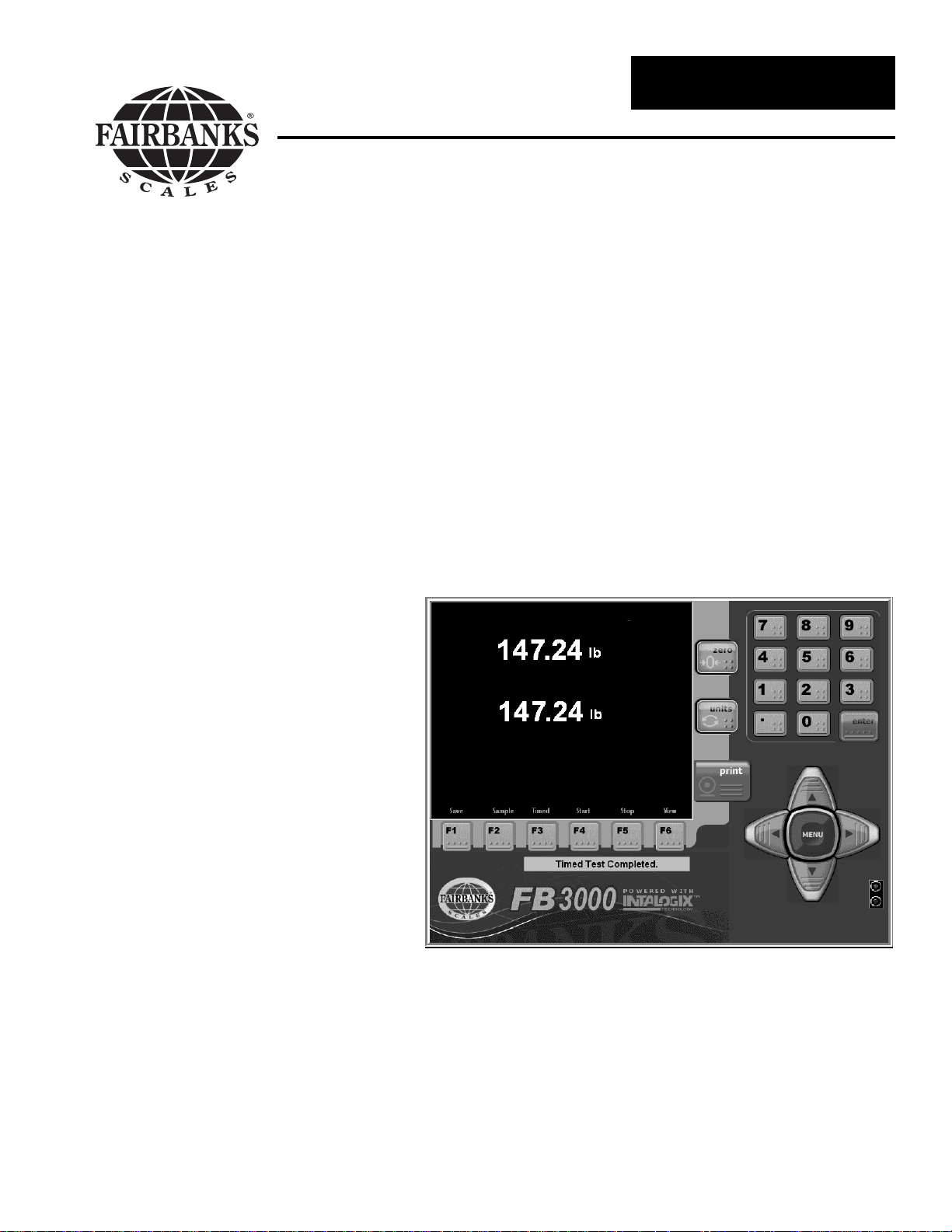
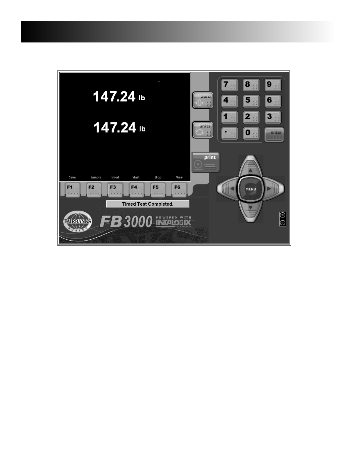
f1 Save As - Saves data file to your designated file name and location.
f2 Sample or Trace - Samples weight on the platform or traces box from on to off scanners.
f3 Timed Dependancy Test - Performs a one (1) hour test of weights captured.
f4 Start - Time Dependancy Test Start which can vary by entering duration time.
f5 Stop - Time Dependancy Test End which will manually stop any test.
f6 View - Allows viewing of records of a test which was performed. Pressing the F6 a sec-
ond time allows viewing of A/D counts from the PC104 card.
B. General Programming Instructions
The programming menus that contain all of the parameters for the system are listed below.
1. Options Menu - Accessible without a password by pressing the MENU key. This menu is
used for general weighing operations and accessing further programming menus.
2. Configuration Menu - This menu is used to enter the parameters for the Keyboard Tare,
AutoTare, Select Scale, Format Ticket, and view the Load Cell Diagnostics. These adjustments aremade by authorized personnel only and is password protected.
3. Service Menu - This menu is used to program the technical parameters of the system,
such as scale capacity, span, and load cell data. These adjustments are made byautho-
rized personnel onlyand is password protected.
4. The following instructions apply to all of the menus.
a. In all menus, the UP or DOWN arrows move the cursor in the indicated direction.
b. To make an entry, place the cursor beside the item to be selected and press the ENTER
key. The operator will be prompted for the data to be entered.
c. AEnter Password prompt means the menu item is locked and can only be accessed
with a password.
d. Data may be entered through the keypad.
e. When the appropriate data has been entered, press the ENTER key to record the data into
memory.
f, Data may also be selected by pressing the right arrow key to toggle to the appropriate
value.
Page 10

50792 10 05/05 Issue #1
C. Options Menu Programming
Weigh Mode Returns the display to the normal weight processing display.
Time & Date Highlight the desired date item, month, day or year, scroll or enter the desired
value. The date may also be selected by scrolling to the desired month and year
and select the day upon the calendar.
Select the desired date format from the drop down box list. Highlight the
desired format and enter.
Select the desired date seperator.
Highlight the desired time item, hour, minutes, or seconds, scroll or enter the
desired value.
Select the desired date format from the drop down box list. Highlight the desired
format and enter.
The revision number at the top right of the screen is the program version num-
ber
Page 11

50792 11 05/05 Issue #1
Ticket Number Enter the ticket number required via the indicator’s numeric keypad or through a
external keyboard accessory.
IN-Motion These values adjust the performance of the systems operation. Once these are
Options configured at installation, the values should not require any further changes.
These adjustments should bemade byauthorized factory trained personnel only.
Enable Weight This value is the weight threshhold which begins the weighing process. This set-
ting will enhance stability if the Gross weight is less than Enable Weight, the dis
play will indicate 0.00 weight . Also if the Gross weight is less than the Enable
Weight for a count equal to the Idle Counter setting, an Auto Zero is performed.
Idle Counter This value is dependant on the speed of the A/D and is used for Auto Zeroing.
Spacing This value is used to shift the start and stop points for weights to be included in
Adjustment box weight calculations. A buffer of box weights (most recent at the top of the
list) is kept for each box from the time it triggers the On Scanner to the time it
triggers the Off Scanner. If there are two boxes on the scale at the same time
a two box error is transmitted. The weights in the final calculation are offset to
exclude two box weighments. The offset value cannot be greater than the spacing adjustment setting.
Page 12

50792 12 05/05 Issue #1
Range The number of weights to include in the calculation before trimming.
Performance Default = 1.0000. If this value is not 1.0000, the final box weight calculation =
Factor box weight + (box weight * Performance Factor). If the Performance Factor
is greater than 1.0000, the final box weights are increased, if less than 1.0000,
the final box weights are decreased.
Box Tolerance If this value is other than the default value of 0.00, any weights read for the box
on the scale that are outside the initial average box weight calculation for this
box are discarded when the final box weight is derived.
Use Peak After Trim Min/Peak trimming has occurred, the Peak Weight of the remaining
Weight Only box weights are used as the final box weight calculation.
Trim Peak The greatest box weight(s) gathered from On to Off Scanner is discarded.
Trim Min The lightest box weight(s) gathered from On to Off Scanner is discarded.
On Scanner 1 Port setting on the Digital I/O card for the on sensor. Default setting: A0
On Scanner 2 Not Used. Port setting for a second on sensor. Default setting: [BLANK].
Off Scanner Port setting on the Digital I/O card for the off sensor. Default setting: A2
Invert Sensors This setting is for the various types of photoelectric sensors. Some sensors are
NPN and others are PNP. NPN sensors = unchecked box. PNP = checked
box.
AutoTare This feature will store the tare of the item on the scale when selected. this fea-
ture is disabled for use with the in motion process. This setting will effect scale
perfomance. For authorized personnel only.
Configuration This menu accesses general configuration functions of the indicator.
Menu This setting will effect scale perfomance. For authorized personnel only.
Ser vice Menu This menu accesses calibration and other metrological functions of the indicator.
This setting will effect scale perfomance. For authorized personnel only.
Page 13

50792 13 05/05 Issue #1
D. Configuration Menu Programming
IN-Motion See Options Menu for parameter descriptions and programming.
Options
AutoTare This feature will store the tare of the item on the scale when selected.This set
ting will effect scale perfomance. For authorized personnel only.
Select Scale This feature will list the number of the scale the indicator is controlling.
Title Not Available with the In Motion System configuration
Field Names Not Available with the In Motion System configuration
Product ID Not Available with the In Motion System configuration
Mail ID Not Available with the In Motion System configuration
Prompts Not Available with the In Motion System configuration
Reports Not Available with the In Motion System configuration
Load Cell This is a diagnostic status display as to the functionality and programming of the
Diagnostics load cell.
Page 14

50792 14 05/05 Issue #1
Communications Ports
The settings for the ports are fixed settings and are not accessible. The data output string for
RS232 / RS422 is shown below:
Baud: 19200 Data Bits: 8 Parity: None Stop Bits: 1
<STX>[Sequence Number]<D>[Track Number][Error][Box Weight][CRC]<CR><LF*>
STX = 0x02
Sequence Number = one (1) character; 1-9 auto incrementing
D = 0x44
Track Number = six (6) characters (6); 1- 999999 auto incrementing
Error = one (1) character. See Error Codes.
Box Weight = four (4) characters. 4 digit box weight. No decimal point.
CRC = four (4) characters. CRC check digit.
CR = 0x0D
LF* = 0x0A; Only added to data string if the file “Include.LF” exists in the c:\NewScale directory.
Error Codes
Bit 0 = 1 = too few box weighments.
Bit 1 = 1 = more than two (2) boxes on the scale.
Bit 2 = 1 = two (2) boxes on the scale.
Bit 3 = 1 = error calculating box weight.
Bit 4 = 0 = always zero (spare bit)
Bit 5 = 0 = always zero (spare bit)
Bit 6 = 0 = always zero (spare bit)
Bit 7 = 1 = always one.
Page 15

50792 15 05/05 Issue #1
E. Service Menu Programming
Update Rate This setting will effect scale perfomance. For authorized personnel only.
Zero Mode This setting will effect scale perfomance. For authorized personnel only.
Tare Mode This setting will effect scale perfomance. For authorized personnel only.
Number of This setting will effect scale perfomance. For authorized personnel only.
Scales
Cell Output When this item is selected, the display
(Counts) will show “Calibration” zero counts and
“Current” zero counts. This display is for
diagnostic information only. Values cannot be changed from this display. The
chart will list all of the cells by number.
Cells which the internal diagnostics
deem suspect or defective will be
highlighted.
Calibration This setting will effect scale perfomance. For authorized personnel only.
Page 16

50792 16 05/05 Issue #1
Write Password This selection allows entry of a password
which can be up to twelve (12) characters
in length. The Write Password function
secures the Configuration, Calibration
and Special Functions programming
areas. Upon entry of the correct value
access is allowed to all of the secured
menu areas. The security is reset upon
exiting to the weight processing screen
This setting will allow changes to the
password. For authorized personnel only.
Print
Calibration
Report This selection will allow viewing or
printing of the calibration and configura
tion parameters of the indicator. It is
recommended a printed copy of this
report be kept by the customer and a
second copy retained by the Service
Center.
Special This selections allows for special
Functions features and functions to be enabled or
performed. See the Special Functions
Menu Programming section for more
details. This setting will effect scale per-
fomance. For authorized personnel only.
Page 17

50792 17 05/05 Issue #1
F. Special Functions Menu Programming
Span (Corners) This setting will effect calibration. For authorized personnel only
System Options This selection allows the keyboard dis-
play to be viewed or hidden. The
selection for Touch Panel (screen)
enable or disable is made in this screen
A check box for the enabling of float
switch detection is also available for
heavy capacity scales.
The Backup and Restore utilities are
located in this menu also. This utility
will perform back ups and will also
restore transactions and the configuration of the system.
Page 18

50792 18 05/05 Issue #1
1. System Backup Proceedure
1. Press MENU key and select the Service Menu choice.
2. Select the Special Functions Menu item.
3. Choose System Options.
4. Press the Backup System Settings button. The system will automatically name the backup file by
date and time performed (yyyymmdd_hhmm.bak).
example: 20041129_1730.bak (November 29, 2004@5:30pm)
The screen will display the backup status.
5. Upon a successful backup, press the MENU key repeatedly until the display is in the weighment
processing screen.
6. The scale is ready to process weights.
Page 19

2. System Restore Proceedure
1. Press MENU key and select the Service Menu choice.
2. Select the Special Functions Menu item.
3. Choose System Options.
4. Press the down arrow in the data box beside the Restore System Settings button. Select the back
up file required. The box will list the backups by date and time performed (yyyymmdd_hhmm.bak).
example: 20041129_1730.bak (November 29, 2004@5:30pm)
5. Upon selection of the backup file, press the Restore System Settings button to restore the settings.
50792 19 05/05 Issue #1
Page 20

50792 20 05/05 Issue #1
6. Press the Yes button to confirm the restore process. Warning ! This will change the system
settings to the values in the backup file selected.
7. The Backup files will be restored in to the scale system. The instrument will re-intialize and return
to the weigh processing screen.
8. The restore process is now complete.
9. The scale calibration should be verified before processing weights. Upon verification, the system
will be ready to process weights
Page 21

50792 21 05/05 Issue #1
A. Basic Operations Summary
There are two options available, In-Motion Gross Weighing and Static Gross-Tare-Net
Weighing.
1. In-Motion Gross Weighing
a. Press the ZERO key to zero the scale.
b. Place the object to be weighed on the approach conveyor. The object will
be moved by the conveyor onto the scale and where it will pass the On
Scanner. The In-Motion system will begin the weighing process and
derive a weight based upon the In-Motion configuration parameter settings. The final processed weight will be displayed upon the object pass
ing the Off Scanner. The final weight will be stored in the transaction
record file and a record will be sent to a monitoring computer.
2. Static Gross Weighing
a. Press the ZERO key to zero the scale.
b. Place the container on the platform.
c. Manually record the weight.
d. Remove the container from the platform.
Section 4: Operation
Page 22

50792 22 05/05 Issue #1
A. Errors
Symptom Solution
Load Cell Failure(s) Weight is behind zero by a large
amount. Check for binds in the
platform.
Load cell has failed. Replace
cell.
No indication from Check for +12vdc.
Green or Red Lamps
for Scanners Check sensor wiring connections
or check for damage.
No Scale Port Found... Check output from High Speed
A/D.
Check interface cable for broken
wires.
Check COM 2 for proper opera-
tion.
Check for loose interface con-
nections
More than two boxes on the scale Check sensor wiring connections
or check for damage.
Two boxes on the scale Check physical box spacing and
spacing programming.
Error calculating box weight Check scale calibration.
Section 5: Service and Maintenance
Page 23

50792 23 05/05 Issue #1
A. Replacement Parts
Item Part Number Description
1 24713 Cover assembly
2 24712 Enclosure
3 24836 Instrument bracket
4 25765 Connector plate
5 25428 Power terminal block plate
6 25362 Terminal block; 6 terminals
7 25363 Terminal block plug; 6 terminals
8 10919 Lock washer int. tooth No. 4
9 10890 Machine screw 4-40 x.25
10 25482 Connector; 3 pos.
11 25483 Contact, female
12 25369 Rocker switch
13 11212 Fully insulated quick disconnect
14 11164 Lug
15 25617 Hard Disk Drive
16 25498 Mini keyboard
17 25499 Mouse
18 25212 Disk drive plate
19 25645 Power cord assembly
20 24117 RJ45 - RJ45 cable assembly
25548 Cable Kit Assembly includes:
22 24890 Keyboard extension cable
24 24892 LVDS Data cable assembly
26 24894 LPT cable assembly
27 24895 LCD Backlight cable assembly
30 25404 PS2 Keyboard- Mouse cable assembly
31 25470 USB cable assembly
32 25388 IDE cable assembly
33 12342 O-ring
34 17534 Liquid tight connector
35 25504 Fully insulated quick disconnect
39 26152 Embedded SBC pcb 1GHz
101 24888 Touchscreen controller pcb
123 24891 Touchscreen cable assembly
130 25109Q USB Digital I/O Interface pcb
131 25389Q USB A-B cable assembly
132 25754 Power supply pcb
133 25769Q Sensor power and signal cable assembly
134 25768Q Power and signal cable assembly
135 25387 COM 2 cable assembly
136 25285 Weight controller pcb
137 25213Q Digital I/O mounting plate
138 15745 Knob
139 12621 Retainer washer
140 25793 Weight controller mounting plate
141 15169 3/4” hole plug
142 25347 1/2” hole plug
N/S 25876Q Load cell damped 50 kg capacity 2 mv/v
N/S 94384 Load cell Junction board
N/S 25674Q Source Sensor
N/S 25675Q Detector Sensor
Section 6: Par ts List
Page 24

50792 24 05/05 Issue #1
1
18
CABLE
INCOMING
20
1
INTERFACE
TO 25284TB1
31
134
CN18
CN22
CN21
40
32
CN15
39
PCB ASSY
COMMUNICATION
27
CN16
26
CN11
DIGITOL I/O
29
23
BK
OR
135
CN9
CN8
130
PMD 1024LS
21
22
21
R
BR
133
JP1
AC/N CN1
3
13
W 11.5"
GRN 9"
CN6
CN5
CN3
24
131
137
J6
132
PCB ASSY
POWER SUPPLY
AC/L
1
10
BLK 11.5"
131
123
2022
CN2
FS1
11
134
133
134
J4
J3
9
8
J1
DISK DRIVE
CA06297B304
32
5
1
TB1
BLK 5"
136
PCB ASSY
WEIGHT CONTROLLER
TB2
4
R
FROM
TB1
W
TB1
15
6
213
G
ON
FRAME
CONVEYOR
C75
BK
20
ETHERNET
22
KEYBD
MOUSE
4
133
135
31
G/Y
GND
WHT
ACC
31
26
BLK
76
AC
DB9F
3
DB9
2
USB
USB
1
DB25
CORD
POWER
B
A
E1
14
140
SW1
101
30
BOTTOM CONNECTOR PLATE
4
19
35
12
17
16
GAP 453124
FOR IN MOTION
3000 SERIES EMBEDDED PC
24
123
27
COVER ASSY
Page 25

50792 25 05/05 Issue #1
COM 2 Mode Select RI / Voltage Select COM 2
JP2 Settings
Definition JP5 Settings Definition
1-2 RS-232 1-2 RI (Default for RS232 and RS422)
3-4 RS-422 3-4 + 5V
5-6 RS-485 5-6 + 12V
COM 2 (A) or COM 2 (B)
Definition
RS232 DB9 RS422/485 DB9
DCD 1
DSR 6
RX 2
RTS 7
TX 3
CTS 8
DTR 4
RI 5V 12V 9
Ground 5
NC 5
485 TX + 2
485 TX - 1
485 RX + 3
485 RX - 4
Appendix I: Communications
COMMUNICATION
PCB ASSY
CN11
CN9
COM 2 JUMPER SETTINGS
CN15
CN11
2
6
2
5
1
JP2
1
{
{
JP5
CN9
 Loading...