

Page 1
Operators Manual
FB6000 SERIES INSTRUMENTATION
FB6001 IN/OUT/ GTN ANALOG DESKTOP INSTRUMENT
FB6002 IN/OUT/ GTN ANALOG NEMA 4X WALL MOUNT INSTRUMENT
© 2012-2013 by Fairbanks Scales, Inc.
All rights reserved
.
Revision 2 01/13
51293
Page 2

Disclaimer
Every effort has been made to provide complete and accurate information in this manual. However,
although this manual may include a specifically identified warranty notice for the product, Fairbanks
Scale makes no representations or warranties with respect to the contents of this manual, and
reserves the right to make changes to this manual without notice when and as improvements are
made.
Fairbanks Scale shall not be liable for any loss, damage, cost of repairs, incidental or consequential
damages of any kind, whether or not based on express or implied warranty, contract, negligence, or
strict liability arising in connection with the design, development, installation, or use of the scale.
© Copyright 2012-2013
This document contains proprietary information protected by copyright. All rights are reserved; no part
of this manual may be reproduced, copied, translated or transmitted in any form or by any means
without prior written permission of the manufacturer
Page 3

Public License Statement
Copyright © 2012-2013, Fairbanks Scales, Inc.
All Rights Reserved
THE FAIRBANKS SCALES COMPANY DEVELOPED SOFTWARE IS PROVIDED BY THE COPYRIGHT HOLDERS AND
CONTRIBUTORS "AS IS" AND ANY EXPRESS OR IMPLIED WARRANTIES, INCLUDING, BUT NOT LIMITED TO, THE
IMPLIED WARRANTIES OF MERCHANTABILITY, FITNESS FOR A PARTICULAR PURPOSE AND NON-INFRINGEMENT
ARE DISCLAIMED. IN NO EVENT SHALL THE COPYRIGHT HOLDER OR CONTRIBUTORS BE LIABLE FOR ANY DIRECT,
INDIRECT, INCIDENTAL, SPECIAL, EXEMPLARY, OR CONSEQUENTIAL DAMAGES (INCLUDING, BUT NOT LIMITED TO,
PROCUREMENT OF SUBSTITUTE GOODS OR SERVICES; LOSS OF USE, DATA, OR PROFITS; OR BUSINESS
INTERRUPTION) HOWEVER CAUSED AND ON ANY THEORY OF LIABILITY, WHETHER IN CONTRACT, STRICT
LIABILITY, OR TORT (INCLUDING NEGLIGENCE OR OTHERWISE) ARISING IN ANY WAY OUT OF THE USE OF THIS
SOFTWARE, EVEN IF ADVISED OF THE POSSIBILITY OF SUCH DAMAGE.
The software included in this Fairbanks Scales, Inc. product includes one or more open source software components. This
product includes software developed by the OpenSSL Project for use in the OpenSSL Toolkit (http://www.openssl.org). This
product also includes software licensed under the Apache License and you may not use any of these files except in compliance
with the Apache License. A copy of the Apache License may be obtained at http://www.apache.org/licenses. This product may
also include the applications governed by the Zlib license, LibPNG license, and the MIT license. For a listing of the open
source software applications included in the product that are governed by any one of the above identified licenses, please
contact Fairbanks Scales, Inc. at the address provided below.
To the extent applicable, Fairbanks Scales, Inc. will comply with the required disclosure conditions set forth in each of the open
source software licenses identified below.
GNU PUBLIC LICENSE:
This Fairbanks Scales, Inc. product includes open source software components governed by the GNU Public License. To the
extent applicable, the person in possession of this product may request a copy of the source code of the software included in
the product that is covered by the GNU Public License. The possessor of this product may request such a copy by contacting
Fairbanks Scales, Inc. at the address set forth below. A copy of the GNU Public License may be found at
http://www.gnu.org/licenses/gpl.html.
GNU LESSER GENERAL PUBLIC LICENSE (LGPL):
This Fairbanks Scales, Inc. product includes open source software libraries governed by the LGPL. The use of the open
source libraries is governed by the LGPL and copies of the source code of these libraries may be obtained by contacting
Fairbanks Scales, Inc. at the address set forth below. A copy of the LGPL license may be found at
http://www.gnu.org/copyleft/lesser.html and a copy of the GNU Public License incorporated into the LGPL is found at the link
provided above.
BSD LICENSE:
This Fairbanks Scales, Inc. product includes open source software governed by the BSD open source license. Your own
redistribution and use in source and binary forms of these Applications, with or without modification, are permitted provided that
the following conditions set forth in the BSD license are met, including:
–
Redistributions of source code must retain the above copyright notice, this list of conditions and the following
disclaimer.
–
Redistributions in binary form must reproduce the above copyright notice, this list of conditions and the following
disclaimer in the documentation and/or other materials provided with the distribution.
A copy of the BSD license may be found at http://opensource.org/licenses/BSD-2-Clause or
http://opensource.org/licenses/BSD-3-Clause.
ARTISTIC LICENSE:
This Fairbanks Scales, Inc. product includes open source software governed by the Artistic License. To the extent applicable,
the person in possession of this product may request a copy of the source code of the portions of the product software that are
covered by the Artistic License or you may find copies of these open source code applications at [www.cpan.org][Fairbanks to
verify location at which user can download source code]. To request a list of the applications and copy of the source code by
contacting Fairbanks Scales, Inc. at the address set forth below. A copy of the Artistic License can be found at
http://opensource.org/licenses/artistic-license-2.0.
Any Open Source Software inquiries to Fairbanks Scales, Inc. shall be sent to: [Fairbanks to provide contact (either person or
the title) and the mailing address.] Any request for copies of the source code will only be provided as required by the license
under which the open source component was used. For any copies of source code provided, a small processing fee of $15.00
may apply to cover the cost of the storage medium and the time required for reproduction.
01/13 3 51293 Rev. 2
Page 4

Amendment Record
FB6000 Series Instrumentation
FB6001 In/Out/ GTN Analog Desktop Instrument
FB6002 In/Out/ GTN Analog NEMA 4X Wall Mount Instrument
Operators Manual
Document 51293
Manufactured by
Fairbanks Scales
821 Locust
Kansas City, MO 64106
Created 12/12 Created
Revision 1 12/12 New Product Documentation Release
Revision 2 01/13 Corrected specification typographical error.
01/13 4 51293 Rev. 2
Page 5

Table of Contents
SECTION 1: GENERAL INFORMATION ................................................................... 8
1.1. Instrument description .......................................................................................... 8
1.1.1. Standard Features........................................................................................................... 8
1.1.2. Accessories ..................................................................................................................... 8
1.2. FB6001/2 Instrument Components ......................................................................... 9
1.3. Technical Specifications ..................................................................................... 10
1.4. General Service Policy ........................................................................................ 12
SECTION 2: SECURITY ........................................................................................... 13
2.1. Levels of Security ................................................................................................ 13
2.2. Supervisor Password .......................................................................................... 14
SECTION 3: USER OPERATIONS .......................................................................... 15
3.1. Front Panel Key Functions ................................................................................. 15
3.2. Operational Procedures ...................................................................................... 16
3.2.1. Gross Weighing ............................................................................................................. 16
3.2.2. Basic Weighing ............................................................................................................. 16
3.2.3. Keypad Stickers for BASIC Operating Mode .................................................................. 17
3.2.4. Gross-Tare-Net Weighing .............................................................................................. 18
3.2.5. Inbound/Outbound Weighing ......................................................................................... 19
3.3. Programming the Operator Menu ....................................................................... 19
3.3.1. Format Time & Date ...................................................................................................... 20
3.3.2. Set Time & Date ............................................................................................................ 20
3.3.3. Ticket Number ............................................................................................................... 21
3.3.4. Load Cell Diagnostics .................................................................................................... 21
3.3.5. New Tare ...................................................................................................................... 22
3.3.6. New Keyboard Tare ...................................................................................................... 22
3.3.7. Utility – Set Display Intensity ......................................................................................... 23
3.3.8. Utility – Key Pad Beep ................................................................................................... 23
SECTION 4: PROGRAMMING ................................................................................. 24
4.1. Programming the Instrument .............................................................................. 24
4.1.1. Login ............................................................................................................................. 25
4.1.2. Short-cut Method for Menu Navigations ........................................................................ 26
4.1.3. Defining the Three Programming Menus........................................................................ 26
4.2. Spreadsheet Menu Overview .............................................................................. 27
4.2.1. Login and Audit Trail Menus Flow Chart ........................................................................ 27
4.2.2. Operator Menu Flow Chart ............................................................................................ 28
4.2.3. Configuration Menu Flow Chart ..................................................................................... 29
4.3. Audit Trail ............................................................................................................ 32
4.3.1. Display .......................................................................................................................... 32
4.3.2. Print .............................................................................................................................. 32
4.3.3. NJ Jumper State ........................................................................................................... 33
4.3.4. SW Revision ................................................................................................................. 33
4.4. Operator Menu ..................................................................................................... 34
01/13 5 51293 Rev. 2
Page 6

Table of Contents
SECTION 5: CONFIGURATION MENU ................................................................... 35
5.1. Change Customer PW ......................................................................................... 37
5.2. Prompts - Programmable .................................................................................... 37
5.3. Legends - Programmable .................................................................................... 38
5.4. Format Tickets ..................................................................................................... 39
5.4.1. Configuring the Printer................................................................................................... 39
5.4.2. Programming the Format Option ................................................................................... 40
5.4.3. Programming the G/T/N Ticket Format .......................................................................... 42
5.4.4. Programming the Inbound Ticket Format ....................................................................... 43
5.4.5. Programming the Outbound Ticket Format .................................................................... 44
5.4.6. Inbound / Outbound Ticket Format ................................................................................ 45
5.4.7. BasicIN and BasicOUT Tickets ...................................................................................... 46
5.4.8. Deleting a Ticket Format ............................................................................................... 47
5.5. Remote Display .................................................................................................... 48
5.6. Programming the COM Ports .............................................................................. 48
5.7. Threshold Weights .............................................................................................. 49
5.8. Traffic Light Control ............................................................................................ 49
5.9. Reports ................................................................................................................. 50
SECTION 6: SERIAL INPUT / OUTPUT .................................................................. 51
6.1. Introduction ......................................................................................................... 51
6.2. Programming the COM Ports .............................................................................. 52
6.3. Configuring the Printer ....................................................................................... 54
6.3.1. Programming the Instrument for a Printer ...................................................................... 54
6.3.2. Select Format ................................................................................................................ 54
6.3.3. Delete ........................................................................................................................... 55
6.4. Printer Switch Settings ....................................................................................... 56
6.4.1. DemandPC ................................................................................................................... 56
6.5. Printer Setup and Programming ......................................................................... 57
6.5.1. OKI ML420 Printer Settings (Serial) ............................................................................... 57
6.5.2. iDP3550 Tape Printer Settings ...................................................................................... 61
6.5.3. TM-U590 Ticket Printer Settings .................................................................................... 62
6.5.4. TM-U295 Ticket Printer Settings .................................................................................... 63
6.5.5. SP298 Printer Settings .................................................................................................. 64
6.5.6. SP700 Printer Settings .................................................................................................. 66
6.5.7. SP2000 Printer Settings ................................................................................................ 68
6.5.8. SP2200 Printer Settings ................................................................................................ 68
6.5.9. TM-U230 Printer Settings .............................................................................................. 69
6.6. 4-20MA Analog Card (30919) ............................................................................... 70
SECTION 7: ACCESSORIES ................................................................................... 71
7.1. Programming the Traffic Light Control .............................................................. 71
7.1.1. Traffic Light Control ....................................................................................................... 71
7.1.2. Event to Signal .............................................................................................................. 72
7.2. Programming the Remote Display ..................................................................... 72
7.2.1. Display Mode ................................................................................................................ 72
7.2.2. Type (Output) ................................................................................................................ 73
7.2.3. Enable 1605T ................................................................................................................ 73
01/13 6 51293 Rev. 2
Page 7

Table of Contents
APPENDIX I: DATA OUTPUT .................................................................................. 74
A. Remote Display Output ....................................................................................... 74
B. Configure Output ................................................................................................. 74
APPENDIX II: REMOTE SWITCH WIRING .............................................................. 80
APPENDIX III: 20MA CODES .................................................................................. 81
APPENDIX IV: REMOTE SERIAL COMMUNICATION COMMANDS ..................... 82
01/13 7 51293 Rev. 2
Page 8

SECTION 1: GENERAL INFORMATION
1.1. INSTRUMENT DESCRIPTION
The FB6001/2 Instrument is a Basic, Inbound, Outbound, and GTN instrument. The
instrument may be enhanced by adding either a 4-20mA or Relay module to the unit.
– Only one (1) module may be added to provide either a 4-20mA output or a
Relay module interface to control traffic lights.
The FB6001/2 Instrument is designed for a wide variety of truck, floor, hopper, and
tank scale applications.
• The load cells interface with the Instrument through the Analog Interface Card.
•
An RS-232 interface allows for the transfer of data from the Instrument to a
computer and vice versa.
•
The two FB6000 Series instrument models are the
Desktop (FB6001)
and the
NEMA 4X Wall Mount (FB6002).
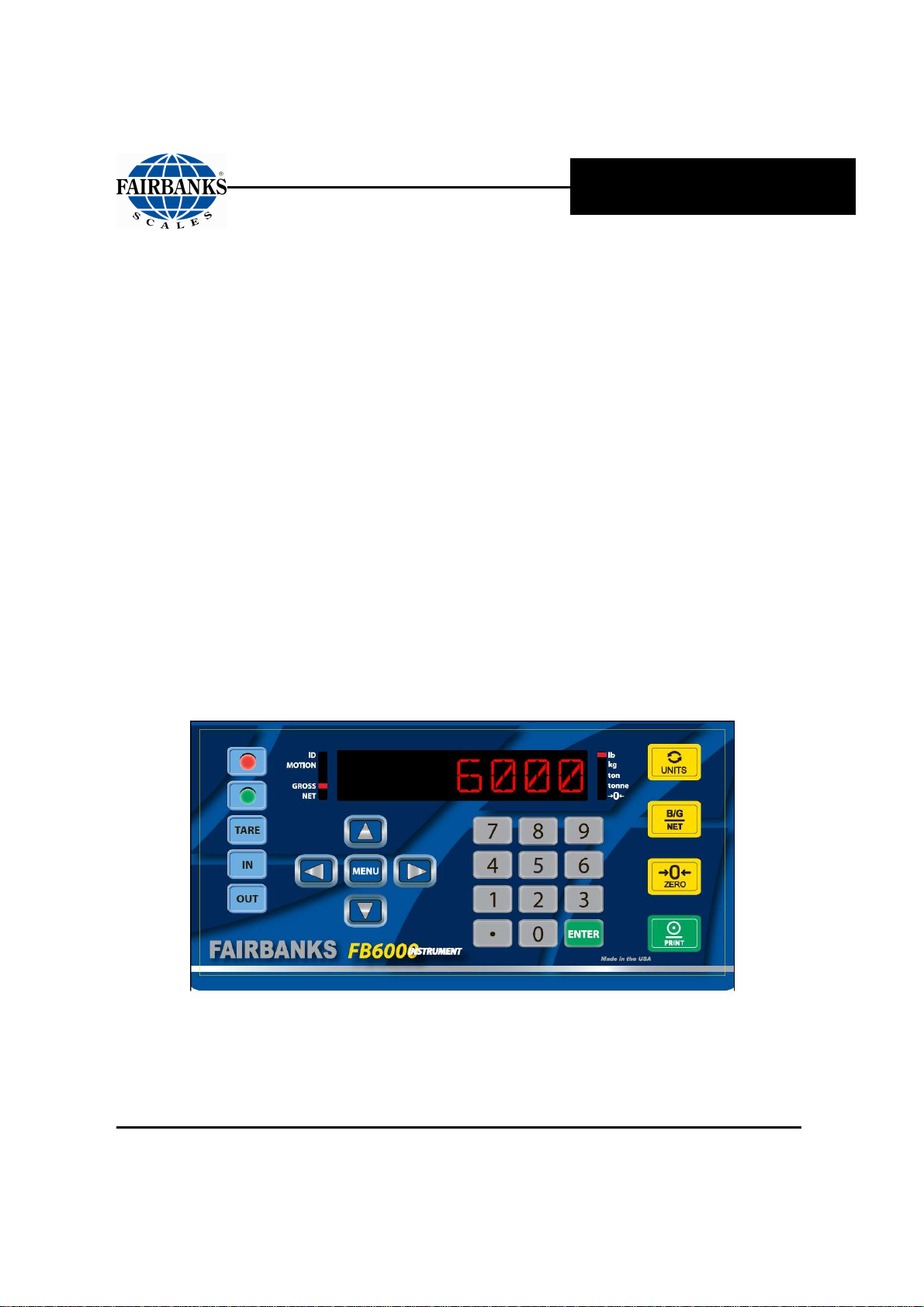
1.1.1. Standard Features
• 1.8” LED alphanumeric display • Three (3) RS232 serial ports
• One (1) Ethernet Port • Capable of formatting tickets
• Three (3) USB Ports • Keypad Buttons, including the following:
• Choice of either One (1) 20mA port or
one (1) Analog Relay Board.
• 0-9 keys, Enter, Red (stop), Green (go), Tare, In,
Out, Units, B/G/Net, Zero and Print.
1.1.2. Accessories
PART NO. DESCRIPTION
30919
30920
25498
31036
15892
4-20mA Analog Kit *
Relay PCB Assy Kit *
Mini USB Keyboard (87 key)
Standard USB Keyboard (104 key)
SVP/ Uninterruptable Power Supply (USB)
* Only one or the other of these accessories may be used in the FB6001/2 series instrument.
01/13 8 51293 Rev. 2
Page 9
Section 1: General Information
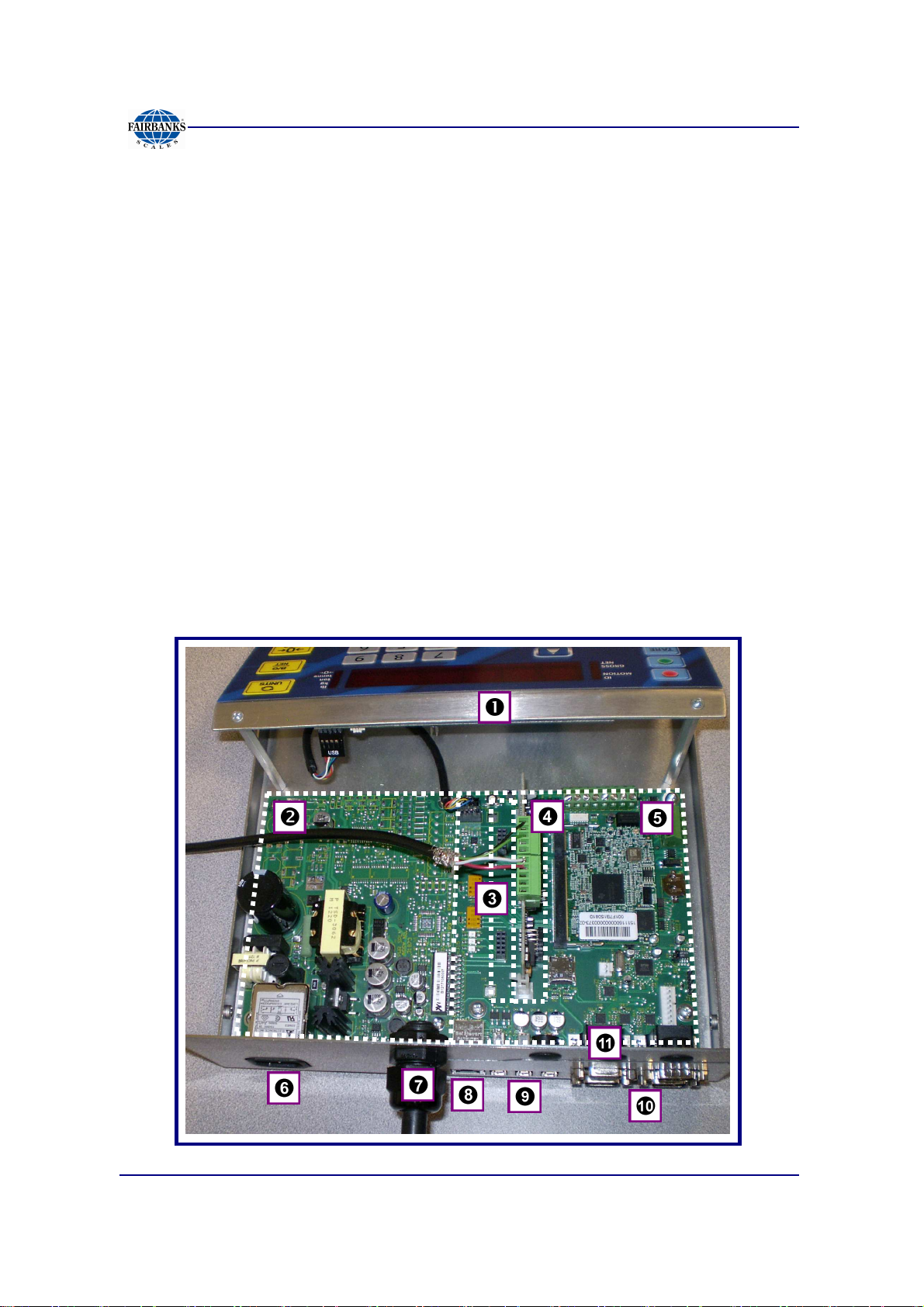
1.2. FB6001/2 INSTRUMENT COMPONENTS
Each FB6001/2 instrument consists of four (4) primary hardware components, as
listed below.
1. Front Panel Assembly
2. Power Supply PCB Assembly
3. One of Two Expansion Modules
─
Analog Relay Card
─
4 to 20mA Card
4. Analog PCB Assembly
5. Base Board (SBC) Assembly
Other elements include the following.
6. Power Cable Outlet 9. Three (3) USB Jacks
7. Load Cell Cable Gland
8. RJ45 Network Cable Port
10. Three (3) RS232 9-pin Serial I/O COM (Ports 1, 2, 3)
11. RS232 Port (Console) for remote programming and
configuration utilities
01/13 9 51293 Rev. 2
Page 10
1.3. TECHNICAL SPECIFICATIONS
PARAMETER SPECIFICATION
Model
Load Cell Interface
Cell Capacity
Cell Units
No. of Scales
Resolution
Scale Capacity
Division Size
Units
Serial Input/ Output
Storage
Auto Zero Tracking
Motion Band
Zero Range
ENVIRONMENTAL SPECIFICATION
Enclosure
Operating Temperature 14°F to 104°F, (–10°C to 40°C).
Operating Humidity NEMA 12 non-condensing, not suitable for wash-down conditions.
POWER REQUIREMENTS SPECIFICATION
Incoming Voltage
Requirement
Ground Requirements For proper performance, the ground should have no more than
Power Consumption Less than (<) 40 watts
ETL Listed
Approvals
Desktop FB6001/2 and NEMA 4X Wall Mount FB6002
Analog Up to 16 ~ 1000Ω load cells max; Excitation = 5vdc,
Or up to 8 ~ 350Ω load cells max
1 thru 999,999
lbs, kgs, tons, tonne
One (1) only
10000d commercial
20000d non-commercial
100-300,000
0.0001 thru 50
lbs, kgs, tons, tonne
Three (3) RS232 COM Ports, one (1) Console Port, three (3) USB
Ports
Up to 100,000 transactions
Selectable – Off, 0.5d, 1.0d, 3.0d
Selectable – Off, 0.5d, 1.0d, 3.0d
Selectable – 2%, 100%
NEMA 12 desk mount; NEMA 4X wall mount
• Instrument has an Auto-switching power supply.
• 100 VAC to 130 VAC, 50Hz\ 60Hz
• 200 VAC to 260 VAC, 50Hz\ 60Hz
• It is recommended to install a separate circuit from the circuit
panel to the outlet used.
• There must not be more than 0.2VAC between AC neutral and
ground
3.0 Ω resistance to true earth ground.
Conforms to UL STD 60950-1.
CAN/CSA C 22.2 NO.60950-1-03.
CC#
12-099
MC#
AM-5878
Section 1: General Information
01/13 10 51293 Rev. 2
Page 11

Section 1: General Information
IMPORTANT INSTALLATION NOTICE
• All load cells, load cell cables and interconnecting cables used to connect all
scale components shall be located
distance away
electric current carrying conductors.
– This includes digital weight Instruments, junction boxes, sectional controllers,
and power supplies.
– This includes any peripheral devices, such as printers, remote displays, relay
boxes, remote terminals, card readers, and auxiliary data entry devices.
– Also included is the scale components themselves, such as 120 volt AC, 240
volt AC, 480 volt AC and electric supply of higher voltage wiring runs and
stations, AC power transformers, overhead or buried cables, electric
distribution panels, electric motors, florescent and high intensity lighting which
utilize ballast assemblies, electric heating equipment, traffic light wiring and
power, and relay boxes.
from all single and multiple phase high energy circuits and
a minimum of thirty-six (36”) inches
• All scale components, including digital weight Instruments and peripheral devices
are not designed to operate on internal combustion engine driven electric
generators and other similar equipment.
• Electric arc welding can severely damage scale components such as digital
weight Instruments, junction boxes, sectional controllers, power supplies, and
load cells.
NOTE:
For additional information, please contact a
Fairbanks Scales Service
Representative.
01/13 11 51293 Rev. 2
Page 12

Section 1: General Information
1.4. GENERAL SERVICE POLICY
It is the customer/operator's responsibility to ensure the equipment
provided by Fairbanks is operated within the parameters of the
equipment's specifications and protected from accidental or
malicious damage.
All electronic and mechanical calibrations and/or adjustments required for
making this equipment perform to accuracy and operational specifications
should be performed by trained service personnel.
Absolutely no physical, electrical or program modifications other than selection
of standard options and accessories are to be made to this equipment.
─
Electrical connections other than those specified may not be
performed, and physical alterations (holes, etc.) are not allowed.
The equipment consists of printed circuit assemblies which must be handled
using ESD handling procedures, and must be replaced as units.
Replacement of individual components is not allowed.
01/13 12 51293 Rev. 2
Page 13
Section 2: Security
2.1. LEVELS OF SECURITY
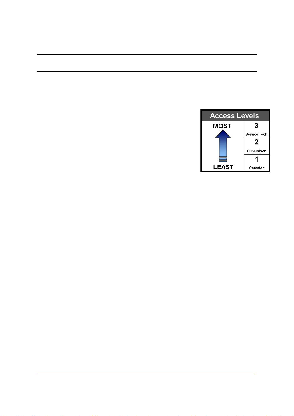
There are three security levels for accessing the FB6001/2 programs.
•
Security Levels One thru Three (1 – 3)
the hierarchy of the management functions, and limits
privilege accesses from unauthorized employees.
• When making the employee hierarchy, employee duties
should determine their security level.
• Each access level includes all of the rights of any access
level(s) below it.
configures
FIRST LEVEL
– Accesses the Operator Menu and the Audit Trail Menu.
– No Password is necessary for this level of instrument access.
: OPERATOR ACCESS
SECOND LEVEL:
– All of the Operator Access privileges.
– Supervisor Password is required.
– The default first time use password for the Supervisor Access is
▪
It is strongly recommended to change this password.
– Second Level Users can also access the
THIRD LEVEL:
– All of the previous level privileges.
– With the Service Password, the technician can also access all menus
options.
SUPERVISOR ACCESS
Configuration Menu
SERVICE TECHNICIAN ACCESS
“1”.
.
01/13 13 51293 Rev. 2
Page 14

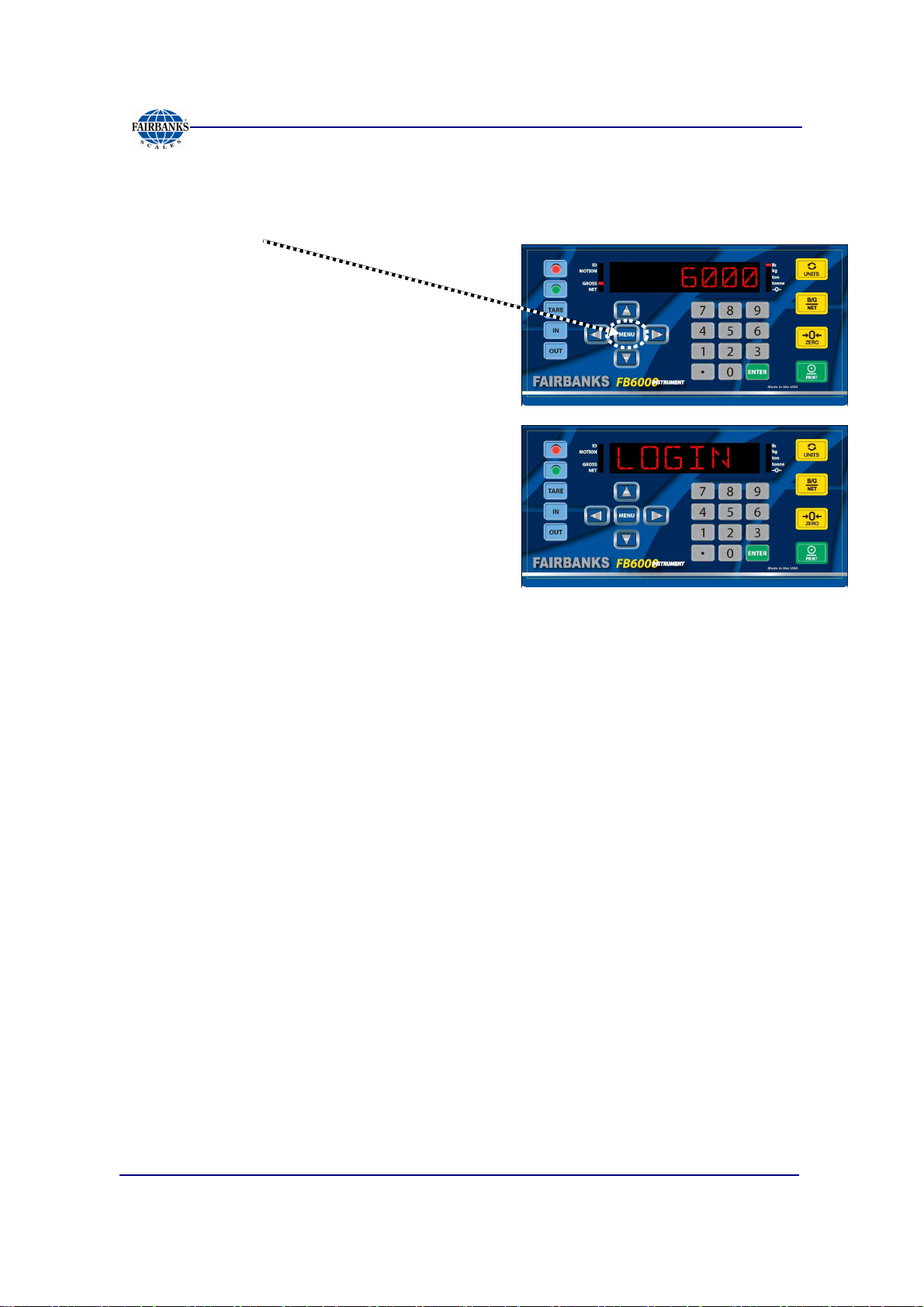
2.2. SUPERVISOR PASSWORD
Section 2: Security
Follow these steps to input the
1. Press
2. When
3. Input the
4. Press
MENU
LOGIN
LOGIN
LOGINLOGIN
.
displays, press
Supervisor Password
ENTER
.
Service Password
ENTER
.
.
and access the Service Menu.
01/13 14 51293 Rev. 2
Page 15
Section 3: User Operations
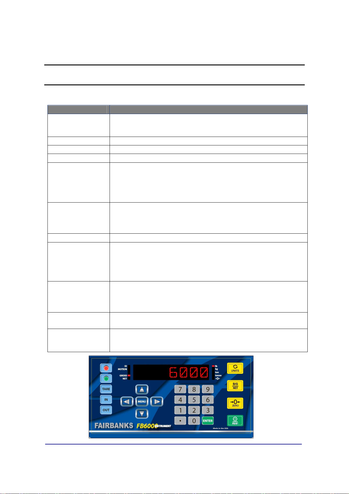
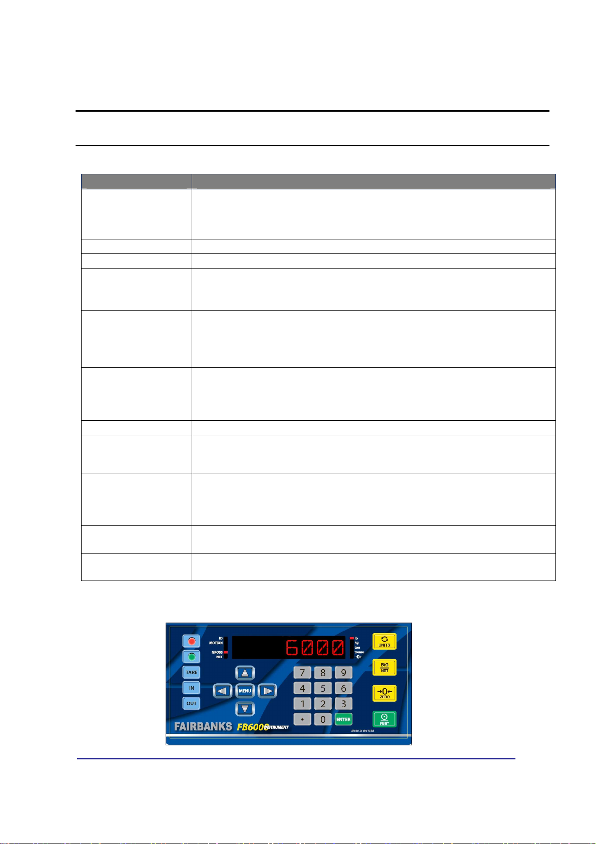
3.1. FRONT PANEL KEY FUNCTIONS
KEYS FUNCTION
RED & GREEN
LIGHT
INSTRUMENTS
TARE
IN & OUT BUTTONS
Arrows
MENU
Numeric Keys
ENTER
UNITS
B/G/NET
ZERO
PRINT
• Activates the Traffic Light function, if one is installed.
• When in the Programming Mode, press the
return to the Weight Display, except when modifying an entry.
Pressing the
Manually selects whether the weighment is IN- or
The
UP
• The
menus, and is the basic Home button.
• It backs up one level on the Menu Tree .
• If the
pressing the
• The
and configuration inputs.
• These keys (Alpha with a keyboard) can shortcut to desired entries in a
selection item (see 5.1.2.Short-cut Method for Menu Navigations).
Press
• The
displayed.
• When programming, it inserts data if additional items are needed.
• Data-insert function happens after the item that is currently being
viewed.
• The
•
BG/NET
Format Menu.
•
B/G/NET
• This button
• When editing numbers or text,
• The
•
PRINT
menu choice
TARE
button performs an AutoTare.
and
DOWN ARROWS
MENU
NUMERIC KEYS
ENTER
UNITS
B/G/NET
PRINT
button initiates the programming process into the different
ENTER
button is not pressed to save the selected option,
MENU
to activate and save any data input.
button toggles and sets the unit types for the weight
key prints the ticket printing configuration while in the
deletes one character in text/number.
ZERO
key initiates a print cycle.
toggles between editing and showing the name of the current
button voids this input..
enter values for passwords, weight amounts,
key initiates the Gross/Tare/Net function.
s the scale.
RED
button to immediately
OUT
- bound.
navigate through the menu selections.
ZERO
will clear the data.
01/13 15 51293 Rev. 2
Page 16

3.2. OPERATIONAL PROCEDURES
3.2.1. Gross Weighing
Section 3: User Operations
1. Press the
2. Drive the vehicle to be weighed on the platform.
3. Once the display stabilizes, press the
– A Gross Weight ticket prints.
ZERO
key.
PRINT
key.
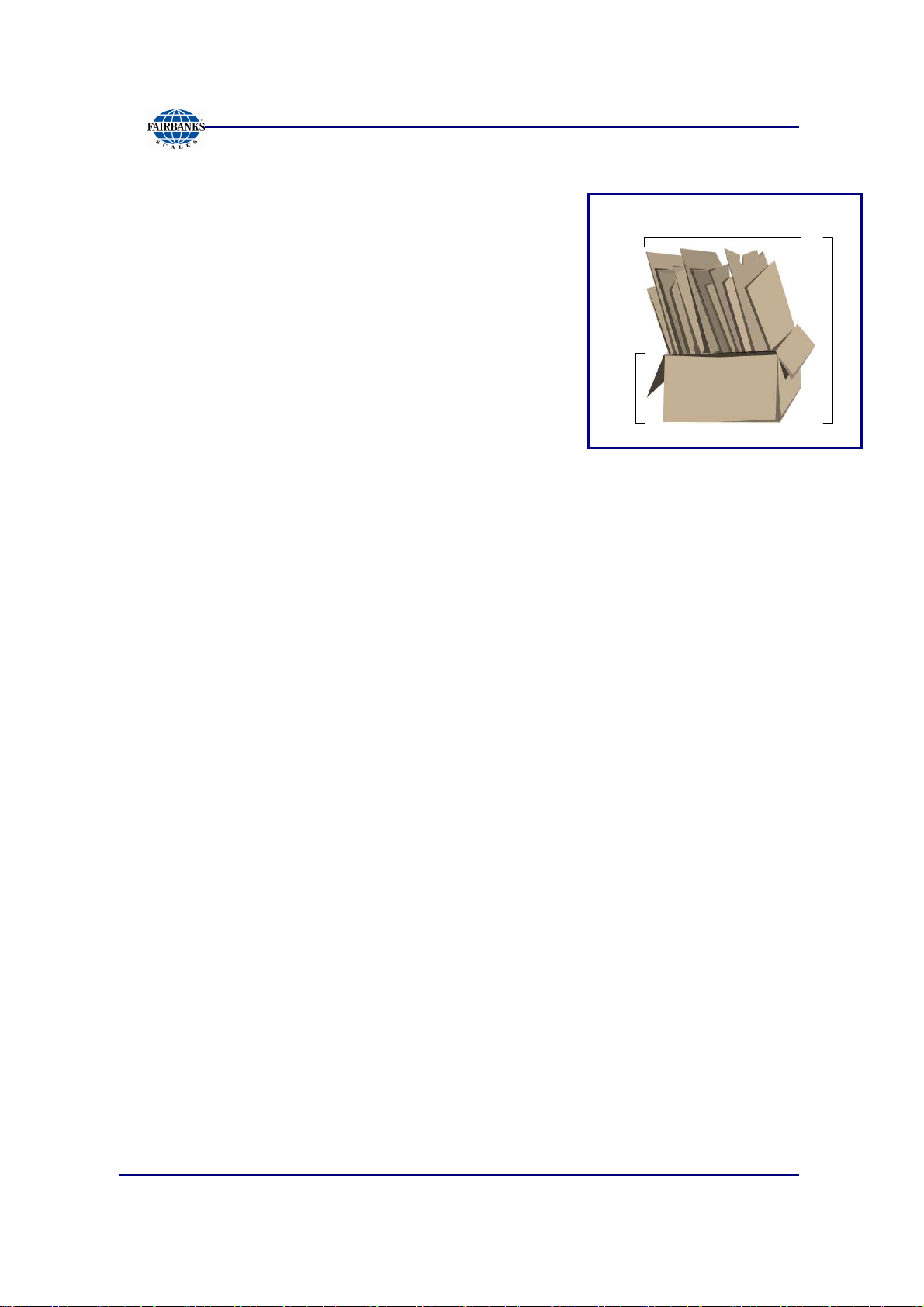
3.2.2. Basic Weighing
BASIC MODE
and Weight Amount (either Tare or Gross) all on one line. This is its only function.
– This mode does not have In/Out or Tare functions, (including storing Tares).
– This mode requires specialized keypad overlay stickers.
1. With a loaded vehicle on the scale, press the
– This is the
2. With an empty vehicle on the scale, press the
– This is the
weighs the vehicle, then prints a ticket displaying the Time, Date
IN KEY
, before the template sticker was added.
OUT KEY
GROSS / PRINT
TARE / PRINT
, before the template sticker was added.
key
key.
NOTE:
See the following page for applying the Keypad Stickers when using the
BASIC Operating Mode.
01/13 16 51293 Rev. 2
Page 17
Section 3: User Operations
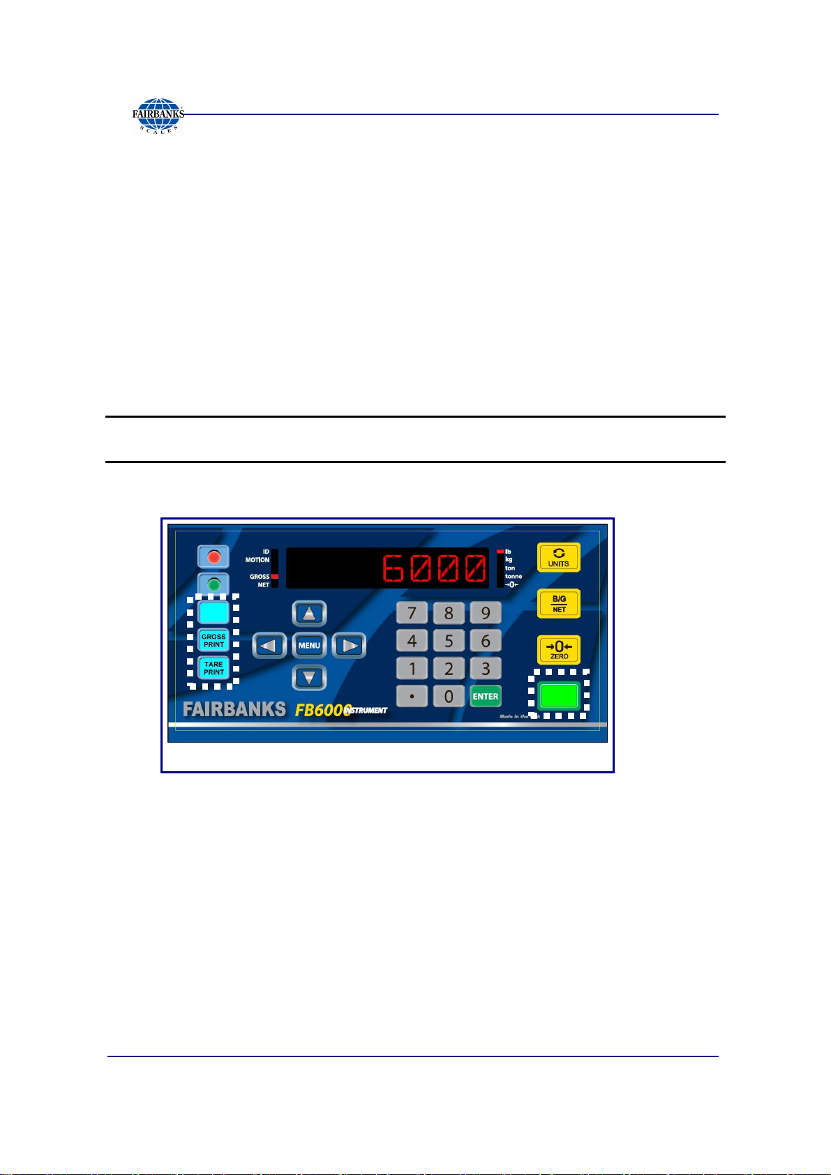
3.2.3. Keypad Stickers for BASIC Operating Mode
Adhere the four (4) REPLACEMENT BUTTON stickers onto the standard keypad
overlay in the following locations.
1. Cover the blue
2. Cover the blue
3. Cover the blue
4. Cover the green
NOTE:
Replace the buttons with these stickers only when using the
Operating Mode (exclusively).
IN button
OUT button
TARE button
PRINT button
with the
with the
with the
with the
GROSS / PRINT sticker.
TARE / PRINT sticker
BLANK sticker
BLANK sticker
.
.
.
Basic
This FB6000 Front Panel image has the BASIC Mode stickers applied.
01/13 17 51293 Rev. 2
Page 18
T
G
Section 3: User Operations
3.2.4. Gross-Tare-Net Weighing
1. Press the
ZERO
key.
NET
2. Drive the vehicle to be weighed on the platform.
1. Press the
TARE
button, and this weight is the
captured Tare Weight.
2. Go off the scale and load the vehicle with product.
3. Drive back onto the scale.
4. Press the
PRINT
key and a Gross-Tare-Net Ticket
A
R
E
will be printed.
– Mode Change – When a
KEY TARE
or
TARE
button is pressed, the scale
automatically switches from the Gross Weighing Mode to the Gross-Tare-
Net Mode.
5. To change the scale from the Gross-Tare-Net Mode back to the Gross
Weighing Mode, press
TARE
and enter a
zero (0)
from the keypad.
R
O
S
S
01/13 18 51293 Rev. 2
Page 19
3.2.5. Inbound/Outbound Weighing
Section 3: User Operations
NOTE: Loop ID
Follow these steps for an INBOUND/OUTBOUND weighment.
1. With the Instrument powered up, press the
2. Drive the vehicle onto the platform, whether it is either full or empty.
3. Press the
4a. Enter the
IN
LOOP ID Number
is NUMERIC only.
(Inbound) key.
ZERO
key.
OR…
4b. Press
5. Drive off the scale and process the trailer, by either filling up or emptying it.
6. The same vehicle returns to the scale, either full or empty.
7. Press the appropriate IN or
8. Enter the
ENTER
to have the FB6001 auto-assign a transaction number.
LOOP ID Number
OUT
button, opposite from the previous weighment.
with the keypad, then press
ENTER
.
The transaction is processed and a ticket prints.
01/13 19 51293 Rev. 2
Page 20
3.3. PROGRAMMING THE OPERATOR MENU
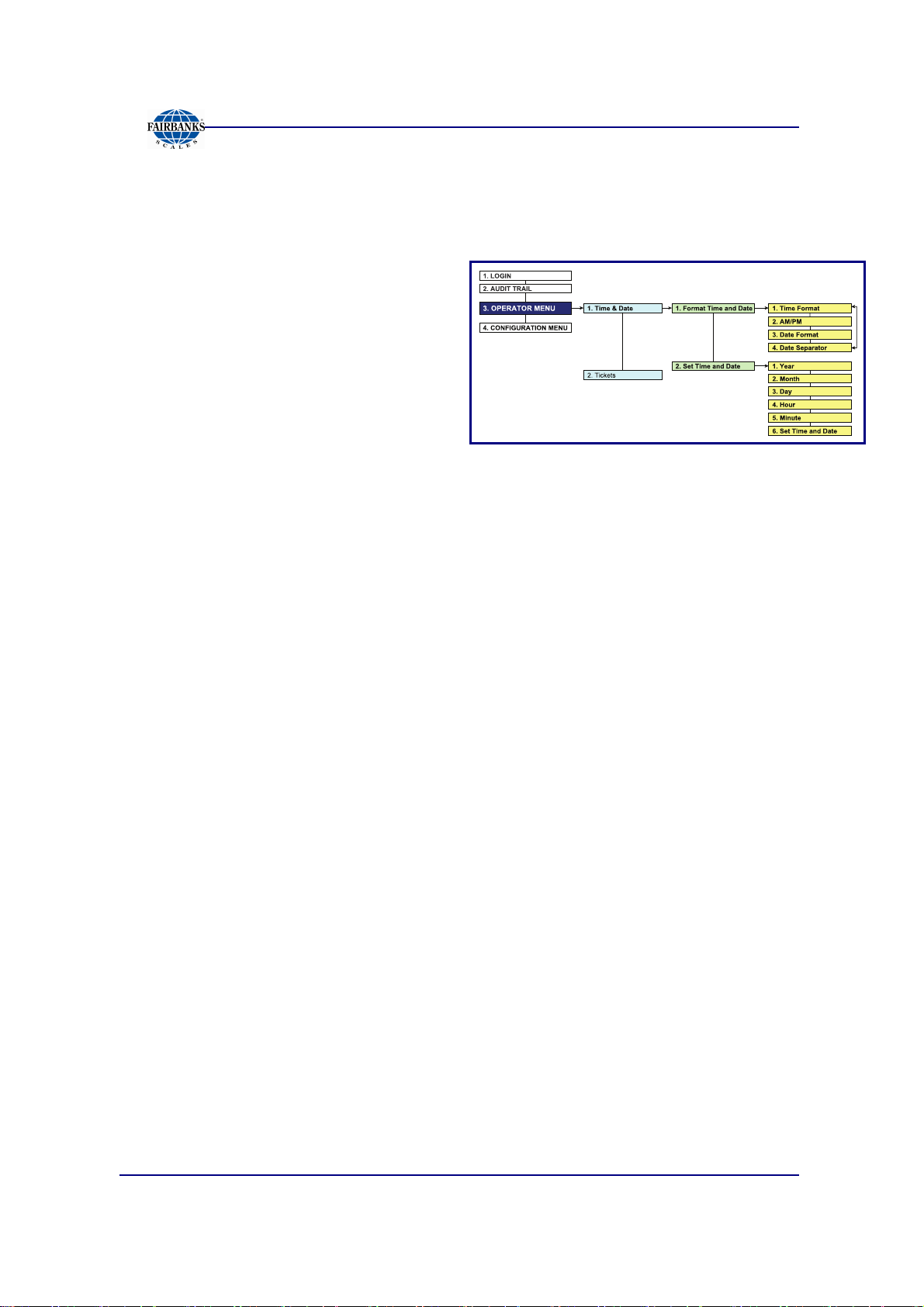
3.3.1. Format Time & Date
Use the Arrow, Numeric MENU and
ENTER Keys to format the time and
date.
1. While in the Operator Menu, select
the
FORMAT TIME AND
FORMAT TIME AND
FORMAT TIME AND FORMAT TIME AND
DATE
DATE
DATEDATE
option, then press
ENTER
.
Section 3: User Operations
2. When
select one of the following options.
3. Open the
4. Touch the
needs.
5. Select one available
and
TIME FORMAT
TIME FORMAT
TIME FORMATTIME FORMAT
• H:M • H:M:S
• HH:MM • HH:MM:SS
AM/PM
AM/PM
AM/PMAM/PM
DATE FORMAT
DATE FORMAT
DATE FORMATDATE FORMAT
----
.
option, which permits 12 hour or 24 hour format.
DATE SEPERATOR
DATE SEPERATOR
DATE SEPERATORDATE SEPERATOR
displays,
, and then select best one for the company’s
formats include(
SPACE
SPACE
SPACESPACE
3.3.2. Set Time & Date
Use the Arrow, Numeric MENU and ENTER Keys to set the time and date.
1. While in the Operator Menu, select the
option, then press
2. Input the
YEAR
YEAR
YEARYEAR
ENTER
, then press
.
ENTER
FORMAT TIME AND DATE
FORMAT TIME AND DATE
FORMAT TIME AND DATEFORMAT TIME AND DATE
.
),
////
,
3. Input the
4. Input the
5. Input the
6. Input the
– The fully programmed time and date will display.
01/13 20 51293 Rev. 2
MONTH
MONTH
MONTHMONTH
DAY
DAY
DAYDAY
HOUR
HOUR
HOURHOUR
MINUTE
MINUTE
MINUTEMINUTE
, then press
, then press
, then press
ENTER
ENTER
ENTER
, then press
.
.
.
ENTER
.
Page 21
Section 3: User Operations
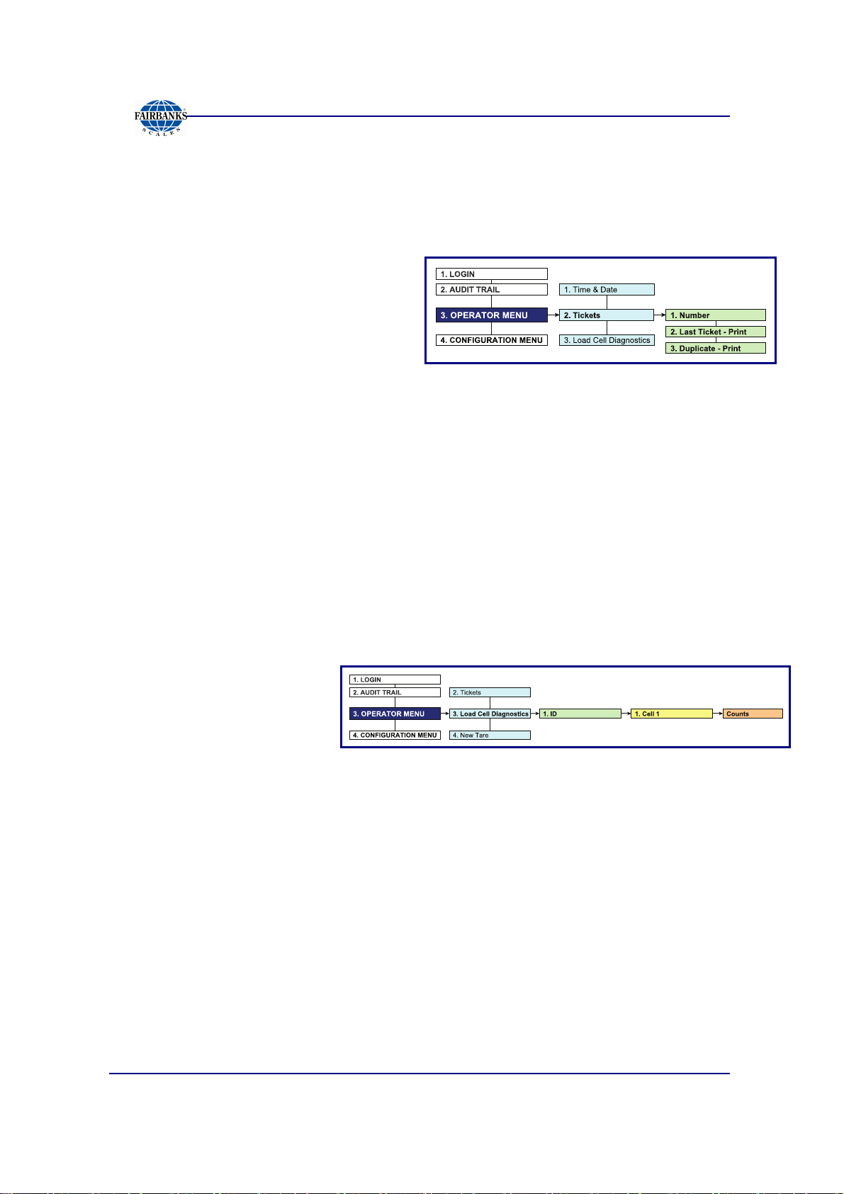
3.3.3. Ticket Number
Follow these steps to access a specific ticket by entering the Ticket Number.
1. While in the Operator Menu, select the
press
2. Type in the
ENTER
– Allows a maximum entry of six (6)
– All the ticket data will display.
3. Press
ENTER
.
digits.
PRINT
.
NUMBER
NUMBER
NUMBERNUMBER
.
, then press
TICKET NUMBER
TICKET NUMBER
TICKET NUMBERTICKET NUMBER
option, then
3.3.4. Load Cell Diagnostics
Load Cell Diagnostics gives a quick snapshot of how each load cell is performing,
used for easier troubleshooting capabilities.
Follow these steps to access the Load Cell Diagnostics option.
1. While in the Operator Menu, select the
option, then press
ENTER
.
LOAD CELL DIAGNOSTIC
LOAD CELL DIAGNOSTICSSSS
LOAD CELL DIAGNOSTICLOAD CELL DIAGNOSTIC
2. When
ENTER
3. When
displays, press
4. When
5. For the complete report, press
The following categories are noted on the print-out.
–
–
–
–
ID
ID
displays, press
IDID
.
CELL 1
CELL 1
CELL 1CELL 1
COUNTS
COUNTS
COUNTSCOUNTS
CELL –
STATUS –
posts a GOOD or BAD condition.
COUNTS –
FLAG –
until flag is manually cleared. This improves the ability to identify intermittent
issues.
ENTER
displays, press
Identifies the load cell in the scale platform.
Compares the load cell output to stored calibration values and
Displays the load cell’s current counts.
Visual flags (
.
ENTER
PRINT
“*”
) identify problem load cell(s) on diagnostic screen
.
.
01/13 21 51293 Rev. 2
Page 22
•
•
•
•
T
G
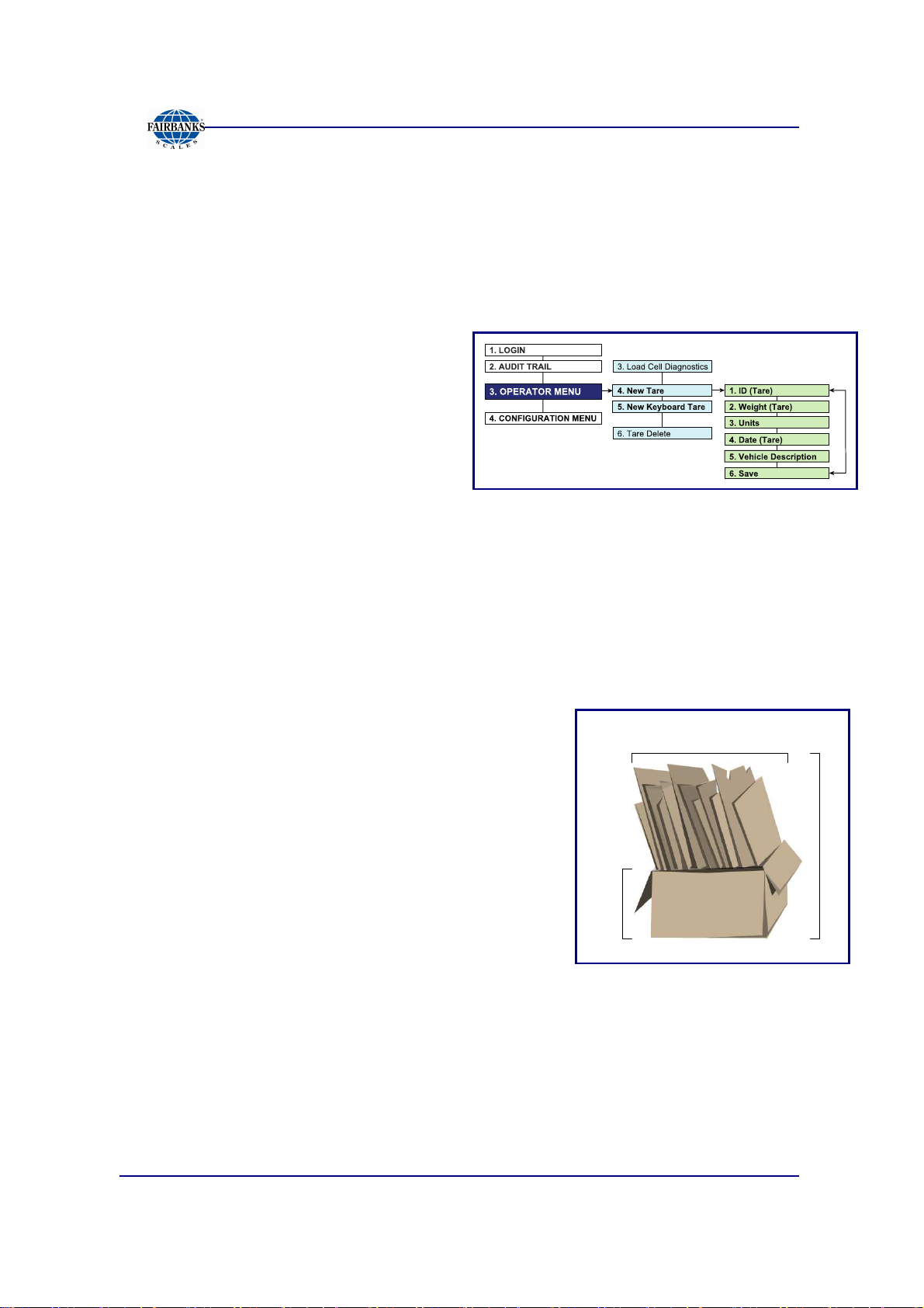
3.3.5. New Tare
Follow these steps to manually enter a New Tare.
Section 3: User Operations
1. While in the Operator Menu, select the
ENTER
2. Press
tare number.
– The program stores a numeric
3. When
displays, enter the amount, then press
ENTER
4. Enter the correct
lb
lb
lblb
5. When
6. Input the
7. This can be the truck drivers’ plate number, the vendor ID, or another designated
identifying number.
.
ENTER
value, recalled later as a saved
tare weight.
WEIGHT <TARE>
WEIGHT <TARE>
WEIGHT <TARE>WEIGHT <TARE>
.
WEIGHT <TARE>
WEIGHT <TARE>
WEIGHT <TARE>WEIGHT <TARE>
when
UNITS
ID <TARE>
ID <TARE>
ID <TARE>ID <TARE>
variable.
kg
kg
kgkg
displays, enter the correct amount.
VEHICLE DESCRIPTION
NEW TARE
NEW TARE
NEW TARE NEW TARE
displays, then input the correct identifying
ton
ton
tonton
, then press
option, then press
ENTER
.
tonne
tonne
tonnetonne
3.3.6. New Keyboard Tare
1. Press the
2. Enter the tare amount.
3. Press
4. Place the object onto the scale.
5. Press the
The
Net Weight
WEIGHT
GROSS WEIGHT –
TARE
ENTER
PRINT
(container only).
button.
.
button.
(product only) is the
TARE WEIGHT
Gross Weight
= NET WEIGHT
(all) minus the
NET
R
O
S
S
A
R
E
TARE
01/13 22 51293 Rev. 2
Page 23
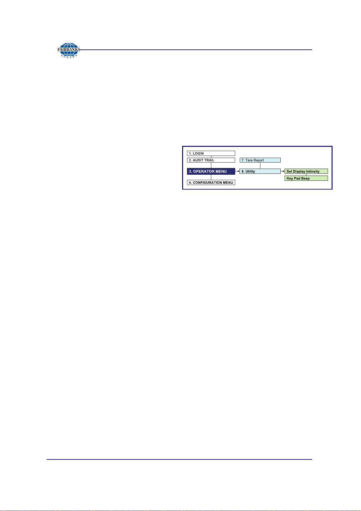
3.3.7. Utility – Set Display Intensity
Follow these steps to set the Display Intensity.
Section 3: User Operations
1. While in the Operator Menu, press the down arrow and select the
option, then press
2. Press
3. Select
ENTER
LOW
LOW, MEDIUM
LOWLOW
ENTER
when
MEDIUM
MEDIUMMEDIUM
SET DISPLAY INTENSIT
SET DISPLAY INTENSITY
SET DISPLAY INTENSITSET DISPLAY INTENSIT
.
or
HIGH
HIGH
HIGHHIGH
, then press
ENTER
Y
appears.
Y Y
.
3.3.8. Utility – Key Pad Beep
1. While in the Utility Menu, press the down arrow and select the
BEEP
BEEP
BEEP BEEP
2. Select
option, then press
ON
ON
or
OFF
ONON
OFF
OFFOFF
, then press
ENTER
ENTER
.
.
KEY PAD
KEY PAD
KEY PAD KEY PAD
UTILITY
UTILITY
UTILITY UTILITY
01/13 23 51293 Rev. 2
Page 24
Section 4: Programming
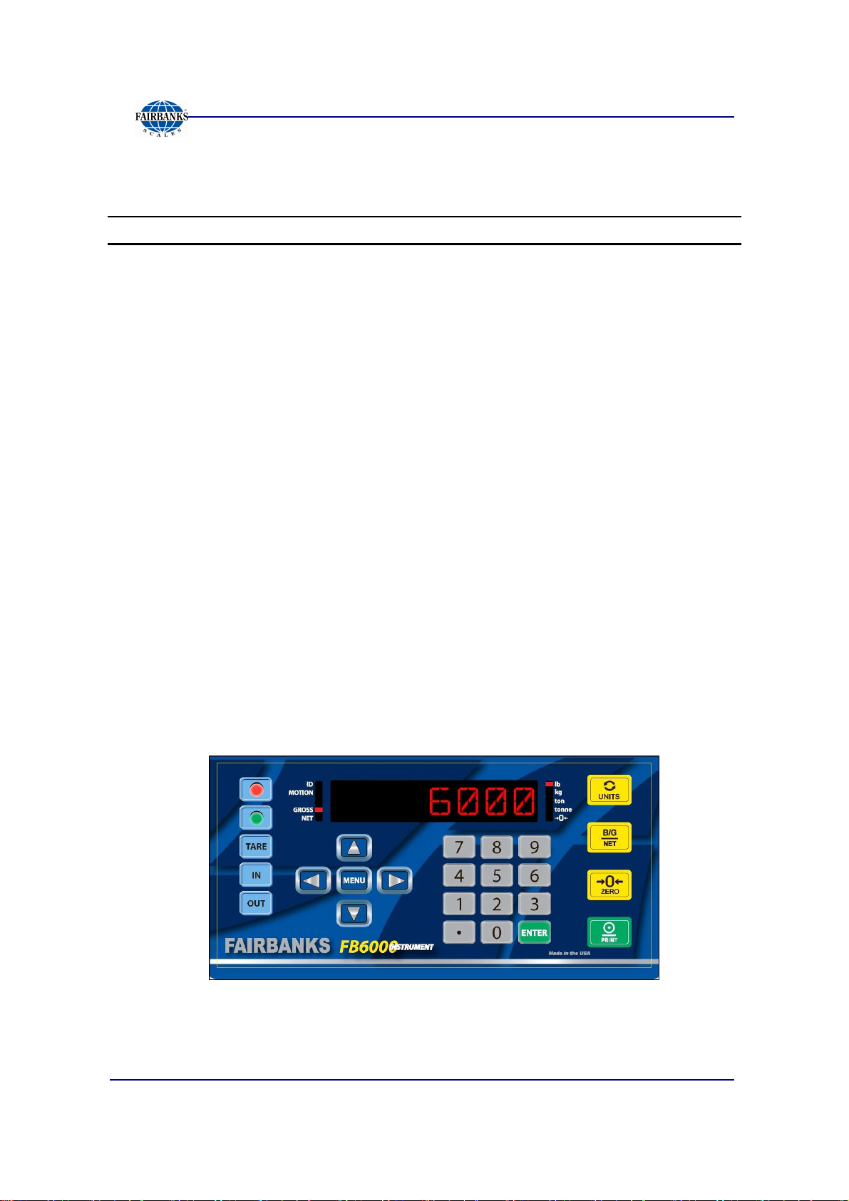
4.1. PROGRAMMING THE INSTRUMENT
KEYS FUNCTION
RED & GREEN LIGHT
INSTRUMENTS
TARE
IN & OUT BUTTONS*
Arrows
MENU
Numeric Keys
ENTER
UNITS
B/G/NET
ZERO
PRINT*
• Activates the Traffic Light function, if one is installed.
• When in the Programming Mode, press the
return to the Weight Display, except when modifying an entry. Exit the
Entry Mode or Audit Mode, then retry.
Pressing the
Manually selects whether the weighment is IN- or
• The UP and
• These keys also modify numbers by increasing or decreasing the value
accordingly.
• The
• It backs up one level on the Menu Tree .
• If the
MENU
• The
configuration inputs.
• These keys (alphanumeric with a keyboard) can shortcut to desired entries in
a selection item (see 5.1.2.Short-cut Method for Menu Navigations).
Press
The
UNITS
Inserts data if additional items are needed. Data-insert function happens after the
item that is currently being viewed.
• The
• This key prints the ticket printing configuration while in the Format
Menu.
• B/G/NET deletes one character in text/number.
• This button
• When editing numbers or text,
• The PRINT key initiates a print cycle.
• PRINT toggles between editing and showing the name of the current menu.
TARE
button manually establishes a Tare Weight.
DOWN ARROWS
MENU
NUMERIC KEYS
ENTER
B/G/NET
button initiates the programming process into the different menus.
ENTER
button is not pressed to save the selected option, pressing the
button voids this input..
enter values for passwords, weight amounts, and
to activate and save any data input.
button toggles and sets the unit types for the weight displayed.
key initiates the Gross/Tare/Net function.
ZERO
s the scale.
RED
button to immediately
OUT
- bound.
navigate through the menu selections.
ZERO
will clear the data.
*
When configured with the BASIC Format, the
OUT key
becomes the
TARE / PRINT button.
IN key
The
becomes the
TARE
and
GROSS / PRINT button
PRINT
keys become non-functional.
, and the
01/13 24 51293 Rev. 2
Page 25
4.1.1. Login
Section 4: Programming
1. Press the
2. To enter the Menu System, press the
ENTER
– The display will be blank.
3. Input the
then press
–
OK
OK
OKOK
MENU
button when
button to toggle between Weight Display and Menu System.
LOGIN
LOGIN
LOGINLOGIN
displays.
SUPERVISOR PASSWORD
ENTER.
displays first, then
AUDIT
AUDIT TRAIL
AUDITAUDIT
,
TRAIL
TRAILTRAIL
follows.
4. Press the
• Audit Trail • Operator Menu • Configuration Menu
5. Press
DOWN ARROW
ENTER
to accept the option.
to navigate through the following main menus.
01/13 25 51293 Rev. 2
Page 26

3 - 2 - 3
4.1.2. Short-cut Method for Menu Navigations
Section 4: Programming
Navigate through the different menu levels by entering a
Hot-key Number
immediately access functions of the next higher level.
– The
Hot-key Number
displays in the flow charts to the left of the function.
Follow these steps to navigate using the Hot-key Numbers.
1. Press a
2. Continue pressing the next
HOT-KEY NUMBER
HOT-KEY NUMBER,
to advance to the functions of the next menu level.
moving forward in the menu tree,
until the needed function is accessed.
3a. Press
ENTER
to access the function,
OR…
Press the Hot-key Numbers
• Press
• Press
ENTER
backward in the menu.
ENTER
to access the function, or
if no number is assigned.
and
to print a duplicate ticket.
MENU
to move
3b. Press
MENU
to move backward to the previous level.
4.1.3. Defining the Three Programming Menus
The three (3) programming menus are briefly defined below.
AUDIT TRAIL
OPERATOR
MENU
CONFIGURATION
MENU
01/13 26 51293 Rev. 2
Identifies how many times and when changes have been made to the
scale’s Calibration or Configuration settings.
Programs the Time/Date, Ticket Number, Load Cell Diagnostics, Tare
Entries, and Display Intensity.
Programs Customer Passwords, Communications Programming and
Functions, Ticket Formats, Programmable Prompts, Device Input/Outputs,
and Weight Threshold.
NO Password required
NO Password required
Default Password = 1
Page 27

4.2. SPREADSHEET MENU OVERVIEW
4.2.1. Login and Audit Trail Menus Flow Chart
Section 4: Programming
01/13 27 51293 Rev. 2
Page 28

4.2.2. Operator Menu Flow Chart
Section 4: Programming
01/13 28 51293 Rev. 2
Page 29

4.2.3. Configuration Menu Flow Chart
Section 4: Programming
This flow chart outlines the
UPPER FUNCTIONS
of the
Configuration Menu.
This includes configuring a Customer Password, Prompts,
Legends, the Printer(s) and the Format Selection.
01/13 29 51293 Rev. 2
Page 30

Section 4: Programming
4.2.3. Configuration Menu Flow Chart, Continued
This section of the flow chart outlines the
FUNCTIONS
See
complete procedures.
01/13 30 51293 Rev. 2
of the
Configuration Menu.
5.4. FORMAT TICKETS
TICKET FORMATTING
and the reading afterward for
Page 31

Section 4: Programming
4.2.3. Configuration Menu Flow Chart, Continued
This flow chart outlines the
This includes Component and Accessory Setups, and Reports configurations.
01/13 31 51293 Rev. 2
LOWER FUNCTIONS
of the
Configuration Menu.
Page 32

4.3. AUDIT TRAIL
The
Audit Trail
were changed within the Instrument.
– It is provided for Weights and Measures Officials.
4.3.1. Display
Defines whether the report
prints data from the
Instrument
platform, or all activities made
from the
Complete
– This option is limited to
view only access.
report displays all the configuration and calibration activities that
, the
Scale
system.
Section 4: Programming
4.3.2. Print
Sets up the print output for the Audit Report, then prints all Configuration and
Calibration activities that were changed within the Instrument.
– Offers a choice of the available printers.
– Prints some or all of the records.
– The PRINT OUT function activates the printer according to the settings.
Follow these steps to print an AUDIT TRAIL report.
1. Prepare the printer.
2. In the Audit Trail Menu, select the correct printer.
•••• TM-U295 •••• TM-U230 •••• SP-700 •••• SP-2000
•••• IDP-2550 •••• TM-U590 •••• SP-298 •••• SP-2200
•••• DemandPC
NOTE:
The printer must be correctly configured before completing this option.
3. Select the Number or Records to include on the report.
• Last (record) • 10 • 50 • All (records)
4. Select
01/13 32 51293 Rev. 2
PRINT OUT
, then press
ENTER
.
Page 33

4.3.3. NJ Jumper State
Follow these steps to set the Audit Trail option.
Section 4: Programming
1. In the Audit Trail Menu, open the
2a. To ENABLE this feature, press the down arrow and select
NJ JUMPER STATE
option.
YES
.
OR…
2b. To DISABLE this feature, select
NO.
4.3.4. SW Revision
This option displays all the current revision information, viewed by the service
technician for references in troubleshooting.
01/13 33 51293 Rev. 2
Page 34

4.4. OPERATOR MENU
The
OPERATOR MENU
– Allows access to change the time, date, ticket number, and the formatting of
the time and date.
– Allows basic diagnostics of the load cells in the scale(s), with beneficial
information for scale operations.
allows basic operations of the instrument.
Section 4: Programming
01/13 34 51293 Rev. 2
Page 35

Section 5: Configuration Menu
Section 5: Configuration Menu
• The image above is a complete overview of the Configuration Menu Flow Chart.
• Each subtopic is expanded and fully defined in the following sections.
• Hold down the CTRL button, then scroll up with the center mouse button to magnify the computer view of this manual
01/13 35 512932 Rev. 2
Page 36

This page is left intentionally blank to allow for double-sided or specialized
printing.
Page 37

•
•
•
•
•
5.1. CHANGE CUSTOMER PW
Section 5: Configuration Menu
1. Press the
2. When
displays, press the
3. Input the new Customer Password.
4. Press
5. When
MENU
ENTER
ENTER PASSWORD
ENTERENTER
ENTER
CONFIRM
CONFIRM PW
CONFIRMCONFIRM
key.
PASSWORD
PASSWORDPASSWORD
ENTER
.
PW
displays, press
PWPW
key.
5.2. PROMPTS - PROGRAMMABLE
1. In the Configuration Menu, press the
PROGRAMMABLE
PROGRAMMABLE
PROGRAMMABLEPROGRAMMABLE
2. Press
3. Press
4. When
5. Press
ENTER
ENTER
NAME
NAME
NAMENAME
ENTER
displays, enter the
when
when
to add the Programmable Prompt to the system.
displays.
PROMPT
PROMPT 1111
PROMPTPROMPT
NAME
NAME
NAMENAME
displays.
displays.
NUMERICAL VALUE
ENTER
again.
DOWN ARROW
until
PROMPTS
PROMPTS
PROMPTSPROMPTS
.
–
6. When
either
GTN
GTN
GTNGTN
Ba
Basic In
BaBa
7. Press
GTN
GTN
GTNGTN
displays, either select
DISABLED
sic In
sic Insic In
ENTER
to confirm this selection.
or
ENABLED
ENTER
for one of the following options.
Inbound
Inbound
InboundInbound
Basic Out
Basic Out
Basic OutBasic Out
or press the down arrow. Choose
Outbound
Outbound
OutboundOutbound
01/13 37 51293 Rev. 2
Page 38

5.3. LEGENDS - PROGRAMMABLE
Section 5: Configuration Menu
1. In the Configuration Menu, press the down arrow until
PROGRAMMABLE
PROGRAMMABLE
PROGRAMMABLEPROGRAMMABLE
2. When
3. Press
LOOP
LOOP ID
LOOPLOOP
ID
IDID
ENTER
to confirm this selection.
displays.
displays, enter the
NUMERICAL VALUE
LEGENDS
LEGENDS
LEGENDSLEGENDS
.
–
01/13 38 51293 Rev. 2
Page 39

5.4. FORMAT TICKETS
Section 5: Configuration Menu
NOTE:
Always configure the
Also see
6.3.1. Programming the Instrument for a Printer
COM Ports
before formatting tickets.
5.4.1. Configuring the Printer
1. In the Configuration Menu, press the down arrow until
TICKETS
TICKETS
TICKETSTICKETS
Press the down arrow to select the correct printer, then press
2. When the
3. Press the down arrow to choose
BASICIN
BASICIN
BASICINBASICIN
4. Press the down arrow to enter either
press
ENTER
BASICIN / BASICOUT MODE
the Time, Date and weight amount all on one line. This is the basic weighing
process only.
displays, then press
SELECT
SELECT FORMAT
SELECTSELECT
, or
.
FORMAT
FORMATFORMAT
BASICOUT
BASICOUT
BASICOUTBASICOUT
weighs the vehicle, then prints a ticket displaying
ENTER
displays automatically, press
GTN
GTN
GTNGTN
, then press
.
,
INBOUND
INBOUND
INBOUNDINBOUND
ENTER
DISABLED
DISABLED
DISABLEDDISABLED
FORMAT
FORMAT
FORMAT FORMAT
ENTER
,
OUTBOUND
OUTBOUND
OUTBOUNDOUTBOUND
.
or
ENABLED
ENABLED
ENABLEDENABLED
.
ENTER
,
, then
.
.
– It weighs either the Gross or the Tare amount.
– This mode does not utilize stored Tares.
01/13 39 51293 Rev. 2
Page 40

5.4.2. Programming the Format Option
Section 5: Configuration Menu
1. In the Configuration Menu, press the down arrow until
TICKETS
TICKETS
TICKETSTICKETS
2. When
PRINTER
PRINTER
PRINTERPRINTER
ENTER.
3. Press the down arrow to access each of the ticket formatting options.
– The default settings for each of the three Operating Modes will display,
allowing each to be altered to fit the customers ticket appearance.
4. After altering any of the formatting parameters, press
move to the next one.
displays, then press
displays, press the down arrow to
ENTER
.
FORMAT
FORMAT
FORMAT FORMAT
FORMAT
FORMAT
FORMATFORMAT
ENTER
, then press
to save it, and
01/13 40 51293 Rev. 2
Page 41

Section 5: Configuration Menu
5.4.2. Programming the Format Option, Continued
Follow these standards when programming with the FB6001/2 Ticket Format.
• All commands are written in the specific order to the ticket. They flow downward,
starting from the top-left of the printer-assigned margin.
• Each command first describes what to do, then in brackets, it defines how many,
the type of action, or exactly what words to display.
• The term
• The term
• Commands with
“Space”
“Feed”
means downward movement (vertical).
<Write Text>
means movement across (horizontal).
are programmable text fields, allowing legends/
prompts to be altered to suit the application needs.
–
Quotation marks
▪
Text can be any character(s) required.
▪
All data items are left justified, and a maximum of fifteen (15) characters long.
• Commands with
<Write>
display the exact word(s) to be printed.
offer a common list of fields which can be printed.
• Certain commands offer two choices, followed by a printed response for one.
“HideWriteOnZero <Tare/Tare>”
.
This means… Hide Tare if Tare = 0. Write (print) the Tare amount if it is > 0.
Defined below are the system generated
Gross
Tare
Net
Date In
Date Out
Time In
Time Out
Units
Ticket Number
Loop ID Text Prints the legend in the Loop ID field, determined by the technician
Loop ID
Prompt 1 Text
Prompt 1 Prints the data from the Prompt 1 Text field.
Inbound
Manual Tare
Duplicate
Prints the Gross Weight.
Prints the Tare Weight.
Prints the Net Weight.
Prints the date of the first weighment.
Prints the date of the final weighment.
Prints the time of the first weighment.
Prints the time of the final weighment.
Prints the Unit choices.
Prints the current ticket number.
(i.e. Truck No., Rail Car No., etc.)
Prints the Loop ID.
Prints the legend to prompt the user to enter an answer or add data
(i.e. BOL No. License, etc.)
Prints the Inbound weight.
Prints any Manual Tare that was input.
Prints that the ticket is a Duplicate.
<Write>
field choices.
NOTE:
An external keyboard accessory is needed for using alphanumeric
characters.
01/13 41 51293 Rev. 2
Page 42

Enhance <”on”>
5.4.3. Programming the G/T/N Ticket Format
Section 5: Configuration Menu
Defined below is the structure and appearance of a
X / Y axis
starting point.
command for
and
bolded print.
Enhance <”off”>
command for restoring
print style to standard.
Gross/Tare/Net
is the
enlarged
is the
ticket.
This image shows the printed areas and other defined
elements of a G/T/N Ticket.
– All grey markings are for illustration purposes only.
Example of an actual G/T/N Ticket.
The flow chart above outlines the
coordinates for each element of
the G/T/N Ticket.
01/13 42 51293 Rev. 2
Page 43

5.4.4.Programming the Inbound Ticket Format
Section 5: Configuration Menu
Defined below is the structure and appearance of an
X / Y axis
starting point.
The image above shows the printed areas and other
defined elements of the ticket.
– All grey markings are for illustration purposes
only, and not printed.
Inbound
ticket example.
The flow chart above outlines
the coordinates for each
element of the Inbound Ticket.
Example of an Inbound Ticket.
01/13 43 51293 Rev. 2
Page 44

Section 5: Configuration Menu
5.4.5. Programming the Outbound Ticket Format
Defined below is the structure and appearance of an
X / Y axis
starting point.
This image shows the printed areas and other
defined elements of the Outbound Ticket.
– All grey markings are for illustration purposes only.
Outbound
ticket example.
This flow chart outlines
coordinates for each element
Actual image of an Outbound Ticket
(without any Inbound Ticket information).
of the Outbound Ticket.
01/13 44 51293 Rev. 2
Page 45

INBOUND TICKET
OUTBOUND TICKET
Section 5: Configuration Menu
5.4.6. Inbound / Outbound Ticket Format
Shown below is a ticket example of a completed Inbound / Outbound transaction.
includes the
DATE, TIME
Weight.
LOOP ID,
, and Initial
includes
the
DATE, TIME, GROSS,
TARE and NET Weights
includes the
and LOOP ID NUMBER.
TICKET NUMBER
. Also
01/13 45 51293 Rev. 2
Page 46

BasicIN
Ticket
Weight
.
BasicOUT
Ticket
Weight
.
BasicIN
Ticket
5.4.7. BasicIN and BasicOUT Tickets
Section 5: Configuration Menu
This image shows the printed areas
and other defined elements of the
BasicIN and BasicOUT Tickets.
X / Y axis
starting point.
includes the DATE,
TIME and
includes the DATE,
TIME and
GROSS
GROSS
BasicOUT Ticket
Actual image of a ticket, processed with
both BasicIN and BasicOUT printing.
01/13 46 51293 Rev. 2
Page 47

5.4.8. Deleting a Ticket Format
Follow these steps to Delete a ticket format.
Section 5: Configuration Menu
1. In the Configuration Menu, press the down arrow until
TICKETS
TICKETS
TICKETSTICKETS
2. Press
3. Press the down arrow until
4. Select
NOTE:
one in the format.
Turn the option off as the last command before the ticket release, or the reports
will invert when they print.
ENTER.
NO
When inverting tickets, the
displays.
or
YES
DELETE
DELETE
DELETEDELETE
to delete the current ticket format.
displays, then press
Invert “On” command
FORMAT
FORMAT
FORMATFORMAT
ENTER
should be the first
.
01/13 47 51293 Rev. 2
Page 48

5.5. REMOTE DISPLAY
Section 5: Configuration Menu
NOTE:
See
Section 7.2. Programming the Remote Display
instructions on this topic.
5.6. PROGRAMMING THE COM PORTS
for complete
NOTE:
01/13 48 51293 Rev. 2
See
Section 6.2. Programming the COM Ports
instructions on this topic.
for complete
Page 49

5.7. THRESHOLD WEIGHTS
Section 5: Configuration Menu
INITIAL WEIGHT
weighment.
– Not used in the Manual Mode of Operation.
Follow these steps to set the Minimum Threshold Weight.
1. In the Configuration Menu, press the down arrow until
WEIGHTS
WEIGHTS
WEIGHTSWEIGHTS
2. Press
3. When
4. Enter the correct amount, then press
ENTER.
INITIAL WEIGHT
INITIAL WEIGHT
INITIAL WEIGHTINITIAL WEIGHT
sets the minimum amount the truck must weigh to initiate a
displays.
displays, press
ENTER.
ENTER
THRESHHOLD
THRESHHOLD
THRESHHOLDTHRESHHOLD
.
5.8. TRAFFIC LIGHT CONTROL
NOTE:
See
Section 7.1. Programming the Traffic Light Control
complete instructions on this topic.
for
01/13 49 51293 Rev. 2
Page 50

5.9. REPORTS
Follow these steps to set the Transaction Reports.
Section 5: Configuration Menu
1. In the Configuration Menu, press the down arrow until
2. Press
3. When
4. Select either
TRANSACTIONS
TRANSACTIONS
TRANSACTIONSTRANSACTIONS
5. When
– A Jump Drive must be inserted into a USB port in order for a report to be
– The Jump Drive must then be inserted into a printer or PC to print the
6. When
Pick either
7. When
–
–
ENTER.
TYPE
TYPE
TYPETYPE
MEDIA TYPE
MEDIA TYPE
MEDIA TYPEMEDIA TYPE
generated.
document or process it further.
SORTED BY
SORTED BY
SORTED BYSORTED BY
DELIMTER
DELIMTER
DELIMTERDELIMTER
CSV (C
Transaction Report.
TAB
– Tabs are used to separate data items in the Transaction Report.
displays, press
COMPLETED TRANSACTIO
COMPLETED TRANSACTIONS
COMPLETED TRANSACTIOCOMPLETED TRANSACTIO
, then press
displays, choose the method of sorting the printed data.
LOOP ID, DATE/TIME
displays, choose one of the two options.
omma Separated Value) – Commas separate data items in the
ENTER
ENTER.
displays, press
or
.
ENTER
TICKET#
NS
NS NS
.
.
REPOR
REPORTS
REPORREPOR
or
INCOMPLETE
INCOMPLETE
INCOMPLETE INCOMPLETE
TS
TSTS
displays.
8. Press
Drive.
–
9. Press
01/13 50 51293 Rev. 2
ENTER
SUCCESS COMPLETE
SUCCESS COMPLETE
SUCCESS COMPLETESUCCESS COMPLETE
MENU
when
to exit.
GENERATE
GENERATE
GENERATE GENERATE
displays to store the Report to the Jump
with the file date and time will display.
Page 51

Section 6: Serial Input / Output
6.1. Introduction
The FB6001/2 Instrument has numerous ports and outlets allowing different Input/
Output devices to be utilized.
• The back of the Instrument has a 120V outlet, but the unit also supports 220V
Scale Input.
• The FB6001/2 instrument has three (3) standard Serial Output COM Ports.
– These are configured for RS-232 communications.
– Serial Outputs can also be customized to provide specific configured data
string protocols, configuration parameters, using output modes such as PC
Polled, PC Continuous, Demand, Off, Remote Display, and then all
printers.
• The Console Port is a RS232 Connection.
– It is designated for remote configuration and diagnostics capability.
• There are three (3) USB Ports used for different external components, such as a
keyboard, USB Flash Drive, etc.
• The three (3) ACC holes are used when wiring external component accessories,
such as a remote display, traffic lights, etc.
01/13 51 51293 Rev. 2
Page 52

6.2. PROGRAMMING THE COM PORTS
Section 6: Serial Input / Output
NOTE:
Follow these steps to program the four (4) COM Ports.
1. In the Configuration Menu, press the down arrow until
2. Press
3. Using the down arrows, select the correct
Always configure the Printer before formatting the tickets.
COM PORTS
COM PORTS
COM PORTSCOM PORTS
displays.
ENTER
press
– COM Ports one thru three (1-3) are standard analog ports.
– COM Port four (4) is dedicated to 20 mA Output, currently used for the
ENTER
Remote Display.
▪
The wires for is device feed through the Gland Nut located on the Instrument’s
back wall, then attach to
.
COM PORT
COM PORT
COM PORTCOM PORT
.
TERMINAL J4
(see image below).
to configure, then
01/13 52 51293 Rev. 2
Page 53

6.2. PROGRAMMING THE COM PORTS, CONTINUED
Section 6: Serial Input / Output
4. When
5. Using the down arrows, select the correct device (noted below), then press
ENTER
• PC Continuous – Displays weight
• PC Polled – Displays weight when
• Off – Does not display weight. • TM-U230 • SP-2000
• Remote Display • TM-U590 • SP-22000
• DemandPC – The external device sends out a polling request (i.e. CR,
6. When
7. Enter the appropriate Port Parameter Settings of the
STOP BITS, DATA BITS, FORMAT
specifications in Section 9.4. Printer Switch Settings.
DEVICE ATTACHED
DEVICE ATTACHED
DEVICE ATTACHED DEVICE ATTACHED
.
continuously.
button is pressed.
“W”, etc.), and the instrument responds with return data. GTN format.
SETTINGS
SETTINGS
SETTINGS SETTINGS
displays, press
displays, press
• TM-U295 • SP-700
• IDP-3550 • SP-298
ENTER
ENTER
.
BAUD RATE, PARITY,
and
CHECKSUM
.
, according to the
01/13 53 51293 Rev. 2
Page 54

6.3. CONFIGURING THE PRINTER
Section 6: Serial Input / Output
Setting up the printer formats is programmed in the
Format Tickets
menus.
Configuration Menu/
6.3.1. Programming the Instrument for a Printer
Follow these steps to setup the Instrument’s Printer.
1. In the Configuration Menu, press the down arrow until
TICKET
TICKETSSSS
TICKETTICKET
2. Press
3. Select one of the eight (8) currently used printers or DemandPC.
• 1. TM-U295 • 4. TM-U590 • 7. SP-2000
• 2. IDP-3550 • 5. SP-700 • 8. SP-2200
• 3. TM-U230 • 6. SP-298 • 9. DemandPC
4. Press
5. When
to enter
ENTER
ENTER
GTN
GTN
GTNGTN
displays.
when
PRINTER
PRINTER
PRINTERPRINTER
when
SELECT
SELECT FORMAT
SELECTSELECT
displays, either press
INBOUND
INBOUND
INBOUNDINBOUND
,
OUTBOUND
OUTBOUND, BASICIN
OUTBOUNDOUTBOUND
displays.
FORMAT
FORMATFORMAT
ENTER
to select it, or press the down arrow
BASICIN
BASICINBASICIN
displays.
FORMAT
FORMAT
FORMATFORMAT
, or
BASICOUT
BASICOUT....
BASICOUTBASICOUT
6. When choosing the mode, press the down arrow to enter either
ENABLED
7. Press
ENTER
.
to confirm this selection.
DISABLED
or
01/13 54 51293 Rev. 2
Page 55

•
•
•
•
•
6.3.2.Select Format
Section 6: Serial Input / Output
1. In the Configuration Menu, press the down arrow until
displays.
2. Press either the
(5) Format Options.
GTN
GTN
GTNGTN
BasicIN
BasicIN
BasicINBasicIN
3. When selecting the mode, press the down arrow to enter either
ENABLED
4. Press
ENTER
ENTER
.
to confirm this selection.
button, or use the down arrow to select one of the five
Inbound
Inbound
InboundInbound
BasicOut
BasicOut
BasicOutBasicOut
SELECT
SELECT FORMAT
SELECTSELECT
outbound
outbound
outboundoutbound
FORMAT
FORMATFORMAT
DISABLED
or
6.3.3. Delete
Follow these steps to Delete a printer format.
1. In the Configuration Menu, press the down arrow until
TICKETS
TICKETS
TICKETSTICKETS
2. Press
3. Press the down arrow until
4. Select
ENTER.
NO
displays.
or
YES
DELETE
DELETE
DELETEDELETE
to delete the current ticket format.
displays, then press
FORMAT
FORMAT
FORMATFORMAT
ENTER
.
01/13 55 51293 Rev. 2
Page 56

6.4. PRINTER SWITCH SETTINGS
Section 6: Serial Input / Output
ROLL TAPE
PRINTER
iDP3550 (SER) 2, 3, 4, 8 1, 2, 3,
TICKET
PRINTER
TM-U590 (SER) 1, 3, 7 All OFF —
TM-U295 (SER) 1, 3 All OFF —
SP298 (SER) All OFF 3 1, 5
SP700 (SER) 1 thru 7 1 thru 6 1, 5
SP2000 (SER) All OFF 3 1, 5
SP2200 (SER) 2, 3, 8 All OFF All OFF
TM-U230 (SER) All OFF 2, 5, 8 —
ML420 (SER) — — —
— No switch bank present inside the printer.
SW 1
ON
SW 1
ON
SW 2
ON
5, 6
SW 2
ON
SW 3
ON
—
SW 3
ON
SWITCH SETTINGS
9600 Baud, No Parity, 8 Data and 1 Stop Bit.
SWITCH SETTINGS
9600 Baud, No Parity, 8 Data and 1 Stop Bit.
9600 Baud, No Parity, 8 Data and 1 Stop Bit.
9600 Baud, No Parity, 8 Data and 1 Stop Bit.
9600 Baud, No Parity, 8 Data and 1 Stop Bit.
2400 Baud, Even Parity, 7 Data and 2 Stop Bit.
2400 Baud, No Parity, 7 Data and 2 Stop Bit.
9600 Baud, No Parity, 8 Data and 1 Stop Bit.
9600 Baud, No Parity, 8 Data and 1 Stop Bit.
• FB6001/2 Desktop use Serial Cable (
25932
) for the printer cable.
NOTE: The Fairbanks Scales standard default switch settings for all
the printers is 9600 Baud, No Parity, 8 Bits, and 1 Stop Bit.
6.4.1. DemandPC
The DemandPC option is used when an external device, such as a light signal or
remote display, sends out a polling request. The FB6000 Instrument responds with
return data to invoke an acknowledgment or action.
– This action is designed for the GTN Format in the Continuous Output Mode.
01/13 56 51293 Rev. 2
Page 57

DB-9
DESCRIPTION
WIRE
DB-25 PRINTER
DESCRIPTION
RS232
RS232
RS232
DB-25
SEL
EXIT
POWER
SHIFT
ALARM
LF
GROUP
Micro Feed
Down
FF/LOAD
Micro Feed
Up
ITEM
MENU
TEAR
SET
PARK
PRINT
QUIET
TOF
SEL
MENU
Section 6: Serial Input / Output
6.5. PRINTER SETUP AND PROGRAMMING
NOTE: The standard default configuration on the COM Ports to all
printers is set at 9600 Baud, 8 data bits, No Parity, and 1 stop bit.
6.5.1. OKI ML420 Printer Settings (Serial)
BAUD
PARITY
DATA BITS
STOP BIT
9600
No
8
1
• For FB6001/2 Instrument Desktop and NEMA 4X SERIAL communications, use
cable
25932
or
14807
• Serial printer only.
Cable
25932
Wiring for COM 1-3
INSTRUMENT
2 RxD BR 2 TxD
3 TxD R 3 RxD
4 DRT O 6 DSR
5 SG Y 7 SG
6 DSR G 20 DTR
7 RTS BL 5 CTS
8 CTS BK 4 RTS
COLOR
Cable
01/13 57 51293 Rev. 2
14807
COM 1
3 3 3 Transmit (Tx) 3
2 2 2 Receive (Rx) 2
5 5 5 Ground (GND) 7
Wiring for COM 1-3
COM 2
COM 3 DESCRIPTION
PRINTER
Page 58

Section 6: Serial Input / Output
6.5.1. OKI ML420 Printer Settings, Continued
Follow these steps to change
1. To enter Menu Mode, press and hold the
SELECT
– The “MENU” legend will be illuminated while in the menu mode.
2. With the printer in the Menu Mode, press
The current default settings print out. It is recommended to use tractor fed paper.
NOTE:
3. Press the
(the group is the left-hand column on the Menu printout).
4. Press the
Item is the center column on the Menu printout).
5. Press the
change (the settings are the right-hand column on the Menu printout).
6. To exit the Menu Mode, press and hold the
SELECT
key.
The printed menu selections are different for each emulation mode.
GROUP
ITEM
SET
key
key to select the relevant group that needs to be changed
key to select the relevant item within the selected group (the
key to cycle through the settings available for the item you want to
MENU SETTINGS
SHIFT
PRINT
SHIFT
.
key while pressing the
key to print the complete menu.
key while pressing the
C A U T I O N !
Turning off the printer before exiting the
will lose any changes made.
MENU mode
01/13 58 51293 Rev. 2
Page 59

Section 6: Serial Input / Output
6.5.1. OKI ML420 Printer Settings, Continued
GROUP ITEMSET
(press LINE FEED(press FORM FEED(press TOF SET
to change)to change) to change)
Printer ControlEmulation ModeIBM PPR
Font Print Mode Utility
Font DRAFT Mode HSD
Font Pitch 10 CPI
Font Proportional Spacing No
Font Style Normal
Font Size Single
Symbol Sets Character Set Set 1
Symbol Sets Language Set American
Symbol Sets Zero Character Slashed
Symbol Sets Code Page USA
Rear Feed Line Spacing 6 LPI
Rear Feed Form Tear-off Off
Rear Feed Skip Over Perforation No
Rear Feed Page Length 11”
Bottom Feed Line Spacing 6 LPI
Bottom Feed Form Tear-off Off
Bottom Feed Skip Over Perforation No
Bottom Feed Page Length 11”
Top Feed Line Spacing 6 LPI
Top Feed Form Tear-off Off
Top Feed Skip Over Perforation No
Top Feed Page Length 11”
Set-Up Graphics Bi-directional
Set-Up Receive Buffer Size 64K
Set-Up Paper Out Override No
Set-Up Print Registration 0
Set-Up Operator Panel Function Full Operation
Set-Up Reset Inhibit No
Set-Up Print Suppress Effective Yes
Set-Up Auto LF No
Set-Up Auto Select No
Set-Up SI Select Pitch (10CP) 17.1 CPI
Set-Up SI Select Pitch (12CPI) 12 CPI
01/13 59 51293 Rev. 2
Page 60

Section 6: Serial Input / Output
6.5.1. OKI ML420 Printer Settings, Continued
GROUP ITEM SETUP
(press LINE FEED(press FORM FEED(press TOF SET
to change)to change) to change)
Printer ControlEmulation ModeIBM PPR
Set-Up Time Out Print Valid
Set-Up Auto Select No
Set-Up Centering Position DEFAULT
Set-Up ESC SI Pitch 17.1 CPI
Set-Up Power Saving Disable
Set-Up Power Save Time 5 Min
Parallel I/F I-Prime Buffer Print
Parallel I/F Pin 18 +5v
Parallel I/F Bi-Direction Enable
Serial I/F Parity None
Serial I/F Serial Data 7/8 Bits 8 Bits
Serial I/F Protocol X-On/X-Off
Serial I/F Diagnostic Test No
Serial I/F Busy Line SSDSerial I/F Baud Rate 9600 BPS
Serial I/F DSR Signal Invalid
Serial I/F DTR Signal Ready on Pwr up
Serial I/F Busy Time 200 ms
01/13 60 51293 Rev. 2
Page 61

DB-9
DESCRIPTION
WIRE
DB-25
DESCRIPTION
1
2
3
4
5
6
7
8
X
X
X
X
X
X
X
X
DS2 ON
OFF
1
2
3
4
5
6
7
8
9
10
X
X
X
X
X
X
X
X
X
X
DS1 ON
OFF
6.5.2. iDP3550 Tape Printer Settings
Section 6: Serial Input / Output
Cable
25932
INSTRUMENT
2 RxD BR 2 TxD
3 TxD R 3 RxD
4 DRT O 6 DSR
5 SG Y 7 SG
6 DSR G 20 DTR
7 RTS BL 5 CTS
8 CTS BK 4 RTS
Wiring for COM 1-3
COLOR
PRINTER
BAUD
PARITY
DATA BITS
STOP BIT
9600
No
8
1
01/13 61 51293 Rev. 2
Page 62

DB-9
DESCRIPTION
WIRE
DB-25
DESCRIPTION
6.5.3. TM-U590 Ticket Printer Settings
Section 6: Serial Input / Output
• For FB6001/2 Instrument Desktop and NEMA 4X
SERIAL communications, use cable
25932.
Set the printer dip switches as listed below.
DSW 1:1, 3, and 7 =
DSW 2:All Switches =
ON
OFF
only.
Cable
25932
INSTRUMENT
2 RxD BR 2 TxD
3 TxD R 3 RxD
4 DRT O 6 DSR
5 SG Y 7 SG
6 DSR G 20 DTR
7 RTS BL 5 CTS
8 CTS BK 4 RTS
Wiring for COM 1-3
COLOR
PRINTER
BAUD
PARITY
DATA BITS
STOP BIT
9600
No
8
1
01/13 62 51293 Rev. 2
Page 63

DB-9
DESCRIPTION
WIRE
DB-25
DESCRIPTION
6.5.4. TM-U295 Ticket Printer Settings
Section 6: Serial Input / Output
• For FB6001/2 Instrument Desktop and NEMA 4X
SERIAL communications, use cable
25932.
.
Set the printer dip switches as listed below.
SW1: 1 and 3 =
Remainder =
ON
OFF
Cable
25932
INSTRUMENT
2 RxD BR 2 TxD
3 TxD R 3 RxD
4 DRT O 6 DSR
5 SG Y 7 SG
6 DSR G 20 DTR
7 RTS BL 5 CTS
8 CTS BK 4 RTS
Wiring for COM 1-3
COLOR
PRINTER
BAUD
PARITY
DATA BITS
STOP BIT
9600
No
8
1
01/13 63 51293 Rev. 2
Page 64

6.5.5. SP298 Printer Settings
Section 6: Serial Input / Output
• For FB6001/2 Instrument Desktop and NEMA 4X
SERIAL communications, use cable
25932.
ACCESSING THE DIP SWITCHES
1. REMOVE ALL POWER FROM THE PRINTER, AS WELL AS ALL NETWORK
CABLES FROM BETWEEN THE PRINTER AND THE INSTRUMENT.
2. Remove the
3. Press down with a screwdriver at
below, and carefully slide the Document Table in the direction indicated by the
arrow until it is out of the way.
– It is not necessary to remove the document table completely. Just move it
enough to access the DIP Switches inside.
4. Set the
5. Slide the Document Table back into place while pressing down at
“A”
.
6. Replace the
Printer Cover
DIP Switches
Print Cover
.
Location “A”
into their correct positions.
.
marked in the illustration
BAUD
PARITY
DATA BITS
STOP BIT
Location
9600
No
8
1
01/13 64 51293 Rev. 2
Page 65

6.5.5. SP298 Printer Settings, Continued
DIP Switch Settings (SERIAL INTERFACE)
Section 6: Serial Input / Output
SWITCH
1
2
3 Data Length
4 Parity Check
5 Parity
6 Handshake DTR/DSR
7
8
9 Pin #6 (DSR) reset signal Enabled
10 Pin #25 (INIT) reset signal Enabled
FUNCTION ON OFF
Baud Rate See table below.
8 bits
Disabled
Odd
Command Emulation See table below
Baud Rate Settings Table
BAUD RATE SWITCH 1 SWITCH 2-2
4800 bps OFF ON
9600 bps
1920 bps ON OFF
3840 bps OFF OFF
ON ON
7 bits
Enabled
Even
XON/XOFF
Disabled
Disabled
Command Emulation Table
COMMAND
EMULATION
Star Mode
ESC/POS (TM-295) ON OFF
ESC/POS (TM-290) OFF OFF
Not used (*) OFF ON
* Never set Switch 7 to
OFF
at the same time that Switch 8 is set to ON.
SWITCH 7 SWITCH 8
ON ON
01/13 65 51293 Rev. 2
Page 66

6.5.6. SP700 Printer Settings
Section 6: Serial Input / Output
• For FB6001/2 Instrument Desktop and NEMA 4X
SERIAL communications, use cable
25932.
BAUD
PARITY
DATA BITS
STOP BIT 1
There are two (2) dip switch locations on the Star SP700 Printer.
– Underneath the printer, behind a protective cover is
–
DIP Switch 2
is on the Serial Interface Board.
DIP Switch 1
DIP
9600
No
8
.
Switch 1
SWITCH
1-1 Always ON
1-2 Auto Cutter *
1-3 Always ON
1-4 Command Emulation
1-5 USB mode **
1-6 2 Colors Printing
1-7 Reserved
1-8 Print head model *** 18-pin wire
*
The factory settings for enabling/disabling the Auto Cutter are as listed below.
– Models without Auto Cutter: Invalid (Switch 1-2 = ON).
– Models with Auto Cutter: Valid (Switch 1-2 =
NOTE: Do not enable the Auto Cutter for models without the Auto Cutter feature
(i.e. models with a tear bar). A mechanical error will occur.
**
USB Interface model only.
***
Do not change the default setting (Switch 1-8 =
FUNCTION ON OFF
Should be set ON
Invalid
Should be set ON
Star
Printer Class
Valid
OFF
OFF
).
Valid
ESC/POS
Vendor Class
Invalid
9-pin wire
).
01/13 66 51293 Rev. 2
Page 67

6.5.6. SP700 Printer Settings, Continued
DIP Switch 2
Section 6: Serial Input / Output
SWITCH
2-1
2-2
2-3 Data Length
2-4 Parity Check
2-5 Parity
2-6 Handshake DTR/DSR
2-7 Pin #6 (DSR) reset signal Valid
2-8 Pin #25 (INIT) reset signal Valid
FUNCTION ON OFF
Baud Rate See table below.
8 bits
Disabled
Odd
XON/XOFF
Baud Rate Settings Table
BAUD RATE SWITCH 2-1 SWITCH 2-2
4800 bps OFF ON
9600 bps
1920 bps ON OFF
3840 bps OFF OFF
ON ON
7 bits
Enabled
Even
Invalid
Invalid
01/13 67 51293 Rev. 2
Page 68

Section 6: Serial Input / Output
6.5.7. SP2000 Printer Settings
The SP2000 is a Dot Matrix ticket printer. The following switch settings and cable
requirements will work with the default format.
• For FB6001/2 Instrument Desktop and NEMA 4X
SERIAL communications, use cable
25932.
Set the printer’s dip switches according to the following:
BAUD
PARITY
DATA BITS
STOP BIT
2400
EVEN
7
1
• DSW 1
• DSW 2:
• DSW 3:
6.5.8. SP2200 Printer Settings
:
All
OFF.
Three (3) ON
One (1)
and
five (5) ON
only.
only.
The SP2200 is a Dot Matrix ticket printer. The following switch settings and cable
requirements will work with the default format.
• FB6001/2 Desktop and NEMA 4X use cable
25932.
BAUD
PARITY
DATA BITS
STOP BIT
2400
NO
7
2
Set the printer’s dip switches according to the following:
•
DSW 1:
•
DSW 2
Two (2), three (3), and eight (8)
and
3:
All
OFF.
ON
only.
01/13 68 51293 Rev. 2
Page 69

6.5.9. TM-U230 Printer Settings
• For FB6001/2 Instrument Desktop and NEMA 4X
SERIAL communications, use cable
BAUD
9600
PARITY
DATA BITS
STOP BIT
No
8
1
DIP Switch 1 Settings (SERIAL INTERFACE)
25932.
Section 6: Serial Input / Output
SWITCH
1 Data receive error Ignored
2 Receive buffer capacity 1KB
3 Handshaking XON/XOFF
4 Work length 7 bits
5 Parity check Yes
6 Parity selection Even
7 Transmission speed 4800 bps
8 BUSY condition Receive
FUNCTION ON OFF
Prints “?”
DTR/DSR
buffer full
buffer full or
DIP Switch 2 Settings (SERIAL INTERFACE)
SWITCH
1 Sections number of characters per
line (cpl) 7 x 9 font/ 9 x 9 font
2 For internal use only (Auto-cutter)
(do not change)
3 Pin 6 reset signal Used Not used
4 Pin 25 reset signal Used Not used
5 PAPER OUT LED flashing pattern
6 For internal use only (flash memory
rewriting) (Do not change)
7 For internal use only (Internal
synchronization) (Do not change)
8 Internal buzzer
FUNCTION ON OFF
42/35
Enabled
Flashes
Enabled
Asynchronous
Disabled
Synchronous
with clock
16KB
8 bits
No
Odd
9600 bps
Receive
Offline
40/33
Disabled
Lights on
Disabled
Enabled
01/13 69 51293 Rev. 2
Page 70

C A U T I O N
ISOLATED POWER SUPPL
Y
CATASTROPHIC DAMAGE!
6.6. 4-20MA ANALOG CARD (30919)
The
4-20 mA ANALOG CARD
High Resolution Output.
4-20mA
Specifications
• A
Current Loop
Voltage
Compliance
Full Scale Setting
Time
• Customer’s external source must furnish 7 to 40 VDC power (typical
• The negative (-) power of the supply MUST be isolated from chassis
• See important
• A separate power supply must be furnished for each output.
– 16 bit resolution +/- .01 integral linearity
PASSIVE DEVICE
current loop voltage.
voltage 24 VDC).
ground
– 8 msecs.
is a Passive Current Loop Device with 16 Bit
CAUTION
Section 6: Serial Input / Output
, as the 4-20 Analog Card is, does not supply any
box below.
Output Impedance
Alarm Current
Total Output Error
Total Output Drift
– 25 Meg Ohms.
– 3.5 to 24mA (underload/overload conditions), Offset at
25°C; +/- .1% of full scale. Offset drift; +/- 25 ppm of full
scale per degree Celsius.
– (20mA) at 25°C: +/- .2% of full scale max.
– +/- 50 ppm of full scale per degree Celsius max.
Above is an example of wiring two (2) passive
nodes with an external power supply.
Failure to have an
WILL CAUSE
01/13 70 51293 Rev. 2
Page 71

Section 7: Accessories
7.1. PROGRAMMING THE TRAFFIC LIGHT CONTROL
The Traffic Light Control shows the status of the scale’s traffic light. It is typically
controlled automatically by the instrument weighment cycle.
• Each
I/O RELAY CARD
supports two (2) sets of lights.
7.1.1. Traffic Light Control
Follow these steps to setup the Traffic Light Control.
1. In the Configuration Menu, press the down arrow until
CONTROL
CONTROL
CONTROLCONTROL
2. Press
3. When
4. When
5. When
down arrow to enter the
6. Press
ENTER.
SCALE
SCALE ID
SCALESCALE
CONTROL
CONTROL TRAFFIC
CONTROLCONTROL
AUTOMATIC
AUTOMATIC
AUTOMATICAUTOMATIC
ENTER.
displays.
ID 1111
IDID
TRAFFIC LIGHT
TRAFFICTRAFFIC
displays, either press
LIGHT
LIGHTLIGHT
displays, either press
MANUAL
MANUAL
MANUALMANUAL
option.
ENTER.
displays, press
ENTER
TRAFFIC
TRAFFIC LIGHT
TRAFFICTRAFFIC
ENTER.
to select it, or press the
LIGHT
LIGHTLIGHT
01/13 71 51293 Rev. 2
Page 72

7.1.2. Event to Signal
Follow these steps to setup the Event to Signal option.
Section 7: Accessories
1. In the Configuration Menu, press the down arrow until
CONTROL
CONTROL
CONTROLCONTROL
2. Press
3. When
4. When
once.
5. When
6. Input a Second Time Delay value from 2 to
7. Press
ENTER.
SCALE
SCALE ID
SCALESCALE
CONTROL
CONTROL TRAFFIC
CONTROLCONTROL
EVENT
EVENT TO
EVENTEVENT
Default = 6 Seconds
ENTER
displays.
ID 1111
IDID
TO SIGNAL
TOTO
.
displays, press
TRAFFIC LIGHT
TRAFFICTRAFFIC
SIGNAL
SIGNALSIGNAL
ENTER.
LIGHT
LIGHTLIGHT
displays, press
displays, press the down arrow
10.
ENTER.
TRAFFIC
TRAFFIC LIGHT
TRAFFICTRAFFIC
LIGHT
LIGHTLIGHT
7.2. PROGRAMMING THE REMOTE DISPLAY
7.2.1. Display Mode
Follow these steps to setup the Display Mode.
1. In the Configuration Menu, press the down arrow until
DISPLAY
DISPLAY
DISPLAYDISPLAY
2. Press
3. When
down arrow to enter
4. Press
ENTER
CONTINUOUS
CONTINUOUS
CONTINUOUSCONTINUOUS
ENTER.
shows.
when
DISPLAY
DISPLAY MODE
DISPLAYDISPLAY
displays, either press
ON
ON PRINT
PRINT
ONON
PRINTPRINT
MODE
MODEMODE
.
shows.
ENTER
REMOTE
REMOTE
REMOTEREMOTE
to select it, or press the
01/13 72 51293 Rev. 2
Page 73

7.2.2. Type (Output)
This option formats what will appear on the Remote Display.
Section 7: Accessories
1. When
OUTPUT
OUTPUT
OUTPUTOUTPUT
2. Select from one of these options.
• Gross Wt • Net Wt • Ticket Number • Active Gross or Net Wt
3. Press
DISPLAY MODE
DISPLAY MODE
DISPLAY MODEDISPLAY MODE
displays, press
ENTER.
ENTER
shows, press the down arrow to
TYPE
TYPE
TYPETYPE
7.2.3. Enable 1605T
1. In the Configuration Menu, press the down arrow until
displays, then press
ENTER
.
ENABLE 160
ENABLE 1605555TTTT
ENABLE 160ENABLE 160
2. Select
YES
YES
YESYES
or
NO
NO
, then press
NONO
ENTER
.
01/13 73 51293 Rev. 2
Page 74

Appendix I: Data Output
A. REMOTE DISPLAY OUTPUT
Data Format
<STX><4><0><SP/-><XXXXXX><ETX>
NOTES:
1. Characters denoted by X are characters 0-9.
2. Leading zeroes are suppressed.
3. Polarity indication for a positive value is a space (SP).
− Negative values are not transmitted.
4. Identifier code <4><0> = Gross weight.
− Transmission is Gross Only.
5. Transmission for the DEMAND Mode occurs when a carriage return
(CR) Hex 0D is received.
B. CONFIGURE OUTPUT
FAIRBANKS DATA FORMAT
<STX><A><B><C><GGGGGG><TTTTTT><CR>
NOTES:
1. Characters denoted by G and T are characters 0-9.
2. Leading zeroes are suppressed.
3. Gross Weight Data = G
Tare Weight Data = T
Status Code (Word) A
Bit # X00 X0 X X.X X.XX X.XXX X.XXXX X.XXXXX
0
1
2
0 1 0 1 0 1 0 1
0 0 1 1 0 0 1 1
0 0 0 0 1 1 1 1
01/13 74 51293 Rev. 2
Page 75

B. CONFIGURE OUTPUT, CONTINUED
FAIRBANKS DATA FORMAT
Increment Size
Bit # Count By 1 Count by 2 Count by 5
3
4
5
1 0 1
0 1 1
Always Logic 1
Appendix I: Data Output
6
7
Always Logic 0
Parity Bit
Status Code (Word) B
Bit # Description
0
1
2
3
4
5
6
7
Gross = 0 Net = 1
Positive = 0 Negative = 1
In Range = 0 Overcapacity = 1
No Motion = 0 Motion = 1
Lb = 0 Kg = 1
Always Logic 1
Normal = 0 Power Up = 1
Parity Bit
Status Code (Word) C
Bit # Description
0
Always Logic = 0
1
Always Logic = 0
2
Always Logic = 0
3
Normal = 0 Print Switch Pushed = 1
4
Always Logic = 0
5
Always Logic = 0
6
Normal = 0 Keyboard Tare = 1
7
Parity Bit
01/13 75 51293 Rev. 2
Page 76

B. CONFIGURE OUTPUT, CONTINUED
Appendix I: Data Output
TOLEDO DATA FORMAT
<STX><A><B><C><GGGGGG><TTTTTT><CR>
NOTES:
1. Characters denoted by G and T are Characters 0-9.
2. Leading zeroes are not suppressed.
3. Gross Weight data = G
Tare Weight data = T
Status Code (Word) A
Bit # X00 X0 X X.X X.XX X.XXX X.XXXX X.XXXXX
0
1
2
0 1 0 1 0 1 0 1
0 0 1 1 0 0 1 1
0 0 0 0 1 1 1 1
Increment Size
Bit # Count By 1 Count by 2 Count by 5
3
4
5
6
7
1 0 1
0 1 1
Always Logic 1
Always Logic 0
Parity Bit
01/13 76 51293 Rev. 2
Page 77

B. CONFIGURE OUTPUT, CONTINUED
Appendix I: Data Output
TOLEDO DATA FORMAT
Status Code (Word) B
Bit # Description
0
Gross = 0 Net = 1
1
Positive = 0 Negative = 1
2
In Range = 0 Overcapacity = 1
3
No Motion = 0 Motion = 1
4
Lb = 0 Kg = 1
5
Always Logic = 0
6
Normal = 0 Power Up = 1
7
Parity Bit
Status Code (Word) C
Bit # Description
0
Always Logic = 0
1
Always Logic = 0
2
Always Logic = 0
3
Normal = 0 Print Switched Pushed = 1
4
Always Logic = 0
5
Always Logic = 1
6
Normal = 0 Keyboard Tare = 1
7
Parity Bit
01/13 77 51293 Rev. 2
Page 78

B. CONFIGURE OUTPUT, CONTINUED
Appendix I: Data Output
CARDINAL 738 CONTINUOUS SCOREBOARD DATA FORMAT
<CR><P><WWWWWW.><M><SP><U><SP><G><SP><SP><ETX>
NOTES:
1. W = Displayed weight
P = Polarity
+ = Positive weight
- = Negative weight
U = Units
lb = pounds
kg = kilograms
M = Motion or O = Overload
G = Gross; N = Net
SP = Space
2. Leading zeros are not suppressed.
WEIGHTRONIX DATA FORMAT
< ><M><WWWWWW>< ><U><CR><LF>
NOTES:
1. < > = Space
M = Mode
G =Gross
T=Tare
N=Net
W = Displayed weight
U = Units
m = Motion
o = Overload
2. Leading zeros are suppressed.
01/13 78 51293 Rev. 2
Page 79

B. CONFIGURE OUTPUT, CONTINUED
CONDEC CONTINUOUS DATA FORMAT
<STX><P><WWWWWW><U><G><M><CR>
NOTES:
1. P = Polarity
space = positive weight
- = negative weight
W = Displayed weight
U = Units
L = pounds
K = kilograms
Appendix I: Data Output
G = Gross; N = Net
M = Motion
2. Leading zeros are suppressed.
01/13 79 51293 Rev. 2
Page 80

Attach
Remote
Switch
wires to
Terminal
J17
Base Board
Appendix II: Remote Switch Wiring
J 17 CONNECTION FUNCTION
1 and 2 Zero
3 and 4 Print
5 and 6 Tare
7 and 8 Gross/Net
of the
.
NOTE:
The Remote Switches and the 20mA share a ground wire.
– This means that remote switches, if used simultaneously with a remote display,
must NOT be grounded. Otherwise they risk creating a ground loop thorough
the instrument’s main circuit board.
– Connect Switch Legs to non-grounded-bonded dry contact only. If the display is
fully isolated (non-bonded), this is not an issue
01/13 80 51293 Rev. 2
Page 81

Appendix III: 20mA Codes
CODE
00
00 –––– Display
Displayssss all data
00 00
DisplayDisplay
CODE UNITS
CODECODE
all data
all dataall data
40
40 Lbs Gross 1
4040
41
41 Lbs Net 1
4141
42
42 Lbs Tare 1
4242
43
43 Kg Gross 1
4343
44
44 Kg Net 1
4444
45
45 Kg Tare 1
4545
UNITS WEIGHT
UNITSUNITS
WEIGHT SCALE #
WEIGHTWEIGHT
SCALE #
SCALE #SCALE #
01/13 81 51293 Rev. 2
Page 82

Appendix IV: Remote Serial
Communication Commands
COMMAND
A
G
LA
LM
R
Txxxxx
U
Z
P
W
DESCRIPTION
Auto Tare weight on scale
Turn Traffic Light Green (Manual Mode only)
Change Traffic Light to Automatic mode
Change Traffic Light to Manual mode
Turn Traffic Light Red (Manual Mode only)
Set Tare on scale (where
Toggle Units on scale
Zero the scale
Print Active scale
Demand request for a Weight output
xxxxx
= tare weight value required)
01/13 82 51293 Rev. 2
Page 83

FB6000 Series Instrumentation
Fairbanks Scales, Inc.
821 Locust
Kansas City, MO 64106
www.fairbanks.com
FB6001 DESKTOP INSTRUMENT
FB6002 NEMA 4X WALL MOUNT INSTRUMENT
OPERATORS MANUAL
DOCUMENT 51293
 Loading...