

Page 1

7
4
PRINT
2
3
1
0
ENTER
8
9
5
6
NET
B/G
MENU
Operator Manual
FB2255 Series Instrument
PC2255
PC Software Utility Program
9
8
7
PRINT
6
4
5
2
1
3
ENTER
0
MENU
B/G
NET
2012-2013 by Fairbanks Scales, Inc.
All rights reserved
51297
Rev. 1 01/2013
Page 2

Page 3

Amendment Record
FB2255
Document 51297
Manufactured by Fairbanks Scales Inc.
821 Locust
Kansas City, Missouri 64106
Created 07/2012
Revision 1 01/2013
Disclaimer
Every effort has been made to provide complete and accurate information in this manual. However,
although this manual may include a specifically identified warranty notice for the product, Fairbanks
Scales makes no representations or warranties with respect to the contents of this manual, and
reserves the right to make changes to this manual without notice when and as improvements are
made.
It is the responsibility of the requesting party to develop, maintain, install, and connect networking
devices and general network connectivity as it applies to the originating party’s network. No warranty
or guarantee, expressed or implied, concerning the network, its design, its installation, or operational
characteristics has been offered by Fairbanks Scales. Fairbanks Scales shall not be liable for any
loss, damage, cost of repairs, incidental or consequential damages of any kind, whether or not based
on express or implied warranty, contract, negligence, or strict liability arising in connection with the
design, development, installation, or use of an intended network.
The Bluetooth® word mark and logos are owned by the Bluetooth SIG, Inc. and any use of such marks
by Fairbanks Scales is under license. Other trademarks and trade names are those of their respective
owners.
© Copyright 2012-2013
This document contains proprietary information protected by copyright. All rights are reserved; no part
of this manual may be reproduced, copied, translated or transmitted in any form or by any means
without prior written permission of the manufacturer.
01/13
3 51297 Rev. 1
Page 4

Table of Contents
SECTION 1: GENERAL INFORMATION ................................................................... 7
1.1.Model Descriptions ................................................................................................... 7
1.2.Main Product Features ............................................................................................. 7
1.3.Specifications ........................................................................................................... 8
1.3.1.Instrument Approvals ................................................................................................... 8
1.3.2.Basic Specifications ..................................................................................................... 8
1.3.3.Standard Settings......................................................................................................... 9
1.3.4.Weight Accumulator ..................................................................................................... 9
1.3.5.Outputs ........................................................................................................................ 9
1.3.6.PC2255 ........................................................................................................................ 9
1.3.7.Power Requirements .................................................................................................... 9
1.3.8.DC Models ................................................................................................................. 10
1.3.9.Out of Range Warnings .............................................................................................. 10
1.3.10.External Printers ........................................................................................................ 10
1.3.11.Environment ............................................................................................................... 10
1.4.Accessories ............................................................................................................ 11
1.5.AC Operation .......................................................................................................... 12
1.6.Powering up the FB2255 ........................................................................................ 12
SECTION 2: USER OPERATIONS ......................................................................... 13
2.1.Front Panel Key Functions ...................................................................................... 13
2.2.Front Panel Programming Parameters .................................................................... 14
2.2.1.Setting the Time ......................................................................................................... 14
2.2.2.Setting the Date ......................................................................................................... 14
2.2.3.Checking Power Supply / Battery Voltage ................................................................... 15
2.2.4.Programming the Sleep Function ............................................................................... 15
2.3.Operating Procedures ............................................................................................ 15
2.4.Gross, Tare and Net Weight ................................................................................... 16
2.5.Basic Weighing ....................................................................................................... 16
2.6.Gross Weighing ...................................................................................................... 17
2.7.Net Weighing .......................................................................................................... 17
2.8.Gross/Tare/Net Weighing ....................................................................................... 17
2.9.Weight Accumulation .............................................................................................. 18
2.10.Number of Accumulations ...................................................................................... 18
2.11.Clearing the Accumulators ...................................................................................... 18
2.12.Piece Counting ....................................................................................................... 19
2.13.Piece Count and Total ............................................................................................ 20
2.14.Peak Weight ........................................................................................................... 21
SECTION 3: SERIAL COMMUNICATION WIRING ................................................. 22
3.1.JP3 Jumper Configuration) ..................................................................................... 22
3.2.TB4 Wiring connections, COM1 (A), COM2 (B), and COM2 (C) ............................. 23
3.3.TB5 Remote Switch Inputs ..................................................................................... 23
3.4. Remote Display Active Keys .................................................................................. 24
01/13
4 51297 Rev. 1
Page 5

Table of Contents
SECTION 4: INPUT / OUTPUT ................................................................................ 25
4.1.3550 Tape Printer ................................................................................................... 25
4.2.Okidata 186 T Form Printer .................................................................................... 25
4.3.Okidata 420 Form Printer........................................................................................ 30
4.4.TM-U295 Ticket Printer ........................................................................................... 33
4.5.TM-U590 Ticket Printer ........................................................................................... 33
4.6.Remote Display ...................................................................................................... 34
4.6.1.Programming the 4-20mA Analog Output mode .......................................................... 35
4.6.2.Programming the 4mA Weight Value .......................................................................... 35
4.6.3.Programming the 20mA Weight Value ........................................................................ 35
SECTION 5: FIELDBUS/BLUETOOTH ................................................................... 36
5.1.Fieldbus Installation ................................................................................................ 36
5.2.Fieldbus Connections ............................................................................................. 37
5.2.1.Overview of Terms ..................................................................................................... 37
5.2.2.DeviceNet (29578) ..................................................................................................... 39
5.2.3.ControlNet (31979) ..................................................................................................... 41
5.2.4.Profibus (29576) ........................................................................................................ 43
5.2.5.Ethernet / IP Diagnostic LEDs .................................................................................... 45
5.3.Bluetooth® Technology Device ................................................................................ 46
SECTION 6: PC2255 UTILITY SOFTWARE ........................................................... 49
6.1.Introduction ............................................................................................................. 49
6.2.Communication Settings ......................................................................................... 49
6.3.Communication Files .............................................................................................. 51
6.4.Menu Bar ................................................................................................................ 51
6.5.Configuration .......................................................................................................... 53
6.6.Calibration .............................................................................................................. 54
6.7.Fieldbus / 4-20 mA .................................................................................................. 54
6.8.Custom Output – Settings ....................................................................................... 58
6.9. Custom Output – Load ............................................................................................. 58
6.10.Custom Output – Build ............................................................................................ 59
6.11.Custom Output – Tokens ........................................................................................ 60
6.12. Custom Output – Weights ...................................................................................... 61
6.13.Formatting Tickets .................................................................................................. 62
6.14.Printed Examples.................................................................................................... 63
SECTION 7: SERVICE AND MAINTENANCE ........................................................ 64
7.1. Troubleshooting the Instrument ................................................................................ 64
7.2.Battery Installation .................................................................................................. 64
01/13
5 51297 Rev. 1
Page 6

Table of Contents
APPENDIX I: DATA OUTPUT FORMATS ............................................................... 65
A.General Notes ........................................................................................................ 65
B.Fairbanks/ Toledo Continuous Output ..................................................................... 65
C.Cardinal 738 Continuous Scoreboard Output .......................................................... 68
D.Weightronics WI-120 Continuous Output ................................................................ 68
E.Condec Continuous Output ..................................................................................... 69
F.Demand Output ...................................................................................................... 69
G.Continuous Output .................................................................................................. 70
H.PLC ........................................................................................................................ 71
I.
UPS ........................................................................................................................ 72
J.P Ship ..................................................................................................................... 73
APPENDIX II: REMOTE PC COMMANDS ............................................................... 75
APPENDIX III: FB2255 REMOTE DISPLAY WIRING .............................................. 77
APPENDIX VI: FB2255 REMOTE DISPLAY ACTIVE KEYS ................................... 78
01/13
6 51297 Rev. 1
Page 7

Section 1: General Information
1.1. Model Descriptions
The FB2255 is a general purpose weighing instrument that can be used with a wide
variety of platforms and load receivers, and is available in eight (8) different
configurations.
MODEL PART NO.
• FB2255-1 Series ABS, AC Power
• FB2255 Series ABS, AC/Battery Power with Bracket
• FB2255-2 Series SS, AC Power
• FB2255 Series SS, AC/Battery Power with Bracket
• FB2255 Series SS, AC Power, No Bracket
• FB2255 Series SS, AC/Battery Power, No Bracket
• FB2255 Series SS, AC Power, No Bracket, IP69K
• FB2255-K Series SS, AC Power, IP69K
32351
32449
32352
32450
32451
32452
32453
32352
1.2. Main Product Features
Major features of the Instrument include the following.
• Push-button programming and calibration.
• Program data is stored in battery supported ram and backed up in flash memory.
– The battery should be replaced every twelve (12) months.
• The FB2255 series instrument features a large one inch (1”) green backlit LCD
weight display, which can be tilted up or down to accommodate different lighting
conditions.
– Microprocessor controlled design allows the instrument to be rapidly
programmed at installation to meet the specific requirements of the
application.
• The obtainable accuracy meets Handbook 44 requirements, and the instrument is
approved for commercial application up to 10,000 divisions.
– A maximum of 100,000 displayed divisions can be programmed for non-
commercial applications.
• A computer utility software program PC2255 is available, downloaded from
Fairbanks Intranet for programming using the computer, and is required for
certain features such as custom ticket formatting.
01/13
7 51297 Rev. 1
Page 8

Section 1: General Information
1.2. Main Product Features, Continued
• The PC2255 software utility program can also upload and modify the instruments
set-up, configuration, and calibration.
– Saved information can be downloaded from a computer to the FB2255 Series
in the event of a catastrophic failure.
• The instrument provides two (2) serial communication ports to provide
communication to various types of peripheral devices for RS232, RS422, RS485,
and 20mA data outputs.
• Optional accessories include a 4-20 mA Analog Output, a Bluetooth® serial
adapter, and three different fieldbus devices; Profibus®, DeviceNet™, and
Ethernet/IP.
1.3. Specifications
1.3.1. INSTRUMENT APPROVALS
• CC
• MC
• ETL
• Conforms to ANSI/UL STD 60950-1
• Certified to CAN/CSA C22.2 STD NO. 60950-1-03
09-023
AM-5720
ETL Listed
1.3.2. BASIC SPECIFICATIONS
• ENCLOSURE
• DISPLAY
• FRONT PANEL KEYS
• UNITS
• GRADUATION SIZE
• AD CONVERSION
• LOAD CELL EXCITATION
• SENSITIVITY
• LOAD CELLS
• DISPLAYED DIVISIONS
• CAPACITIES
ABS, Black NEMA 1, Stainless Steel NEMA 4X Desk and Wall
Mount
6-digits, One inch (1”) LCD, Green Backlight
On/Off, Units, Zero, B/G, Net, Tare and Print
lbs., oz, kg, g and lbs/oz, or custom
0.0001 to 50
66 per second
5 Volts DC
1µv/d (microvolt/division)
Eight (8) 350 ohm or Sixteen (16) 1000 ohm
10,000d Commercial and 100,000d Non-Commercial
Programmable to 999999
01/13
8 51297 Rev. 1
Page 9

Section 1: General Information
1.3. Specifications, Continued
1.3.3. STANDARD SETTINGS
• Zero Range
• Auto Zero Tracking
• Balance
• Filter
• Display Update Rate
Off, 2 % or 100%
OFF, 0.5, 1 or 3 divisions
OFF, 0.5, 1 or 3 divisions
Slow, Animal, Standard, and Fast
0.2, 0.4, and 0.8 seconds
1.3.4. WEIGHT ACCUMULATOR
• Capacity
999,999 Weight Units
– Printed or viewed.
1.3.5. OUTPUTS
• PORT 1
• PORT 2
Bidirectional Serial Port. Settings include OFF, RS232, RS422,
and RS485. RS232 has 30+ updates a second
Port 2 is used to interface to the PC2255 program,
OR,
Provide 20 mA passive, RS232, RS422,or RS485.
1.3.6. PC2255
• Computer software utility program is available for your local Fairbanks Representative.
• PC2255 is required for setting certain aspects of programming, such as custom Units and custom
ticket formatting.
1.3.7. POWER REQUIREMENTS
• 117 volts AC +/- 10 %
• 220 volts AC +/- 10 %
• < 0/2 volts AC between Neutral and Ground
• 1.5 watts maximum
• The FB2255 is designed to operate from 80 to 260 volts AC, 50 to 60 Hertz
01/13
9 51297 Rev. 1
Page 10
Section 1: General Information
1.3. Specifications, Continued
1.3.8. DC MODELS
• Batteries
• Battery Life
• Internal Battery
Five (5) Size “D” Alkaline batteries @ 1.5 Volts DC each.
• Up to forty (40) Hours or greater with a maximum load of 4, 350 load
cells and backlighting enabled.
• Battery usage time can be adversely affected by battery storage,
battery capacity and battery brand.
• To maximize battery life, Serial Ports 1 and 2 should be switched
OFF, if not used.
• Should be replaced every 12 months using Panasonic CR 1220 3V or
equivalent.
1.3.9. OUT OF RANGE WARNINGS
• HiCAP
• - - - - - - -
• Sleep Mode
• Time and Date
Scale input is over capacity
Displayed weight exceeds 6 digits
Settings include OFF, 1, 2, 5, 10, 20, and 30 minutes
Battery Maintained
1.3.10. EXTERNAL PRINTERS
• Citizens IDP 3550 Tape Printer
• Okidata 184 & 186 Serial Form Printer
• Okidata 420 Serial Form Printer
• Epson Models TM-U295 and TM-U590 Ticket Printers
1.3.11. ENVIRONMENT
• Temperature
• Storage Temp.
01/13
-10ºC to + 40ºC (+14ºF to + 104ºF)
-40ºC to + 60ºC (-40ºF to + 140ºF)
10 51297 Rev. 1
Page 11

Section 1: General Information
1.4. Accessories
Optional accessories include the following.
FIELDBUS DEVICES
• DeviceNet™ • ControlNet™ • Profibus® • Ethernet/IP
4-20 MA ANALOG CURRENT LOOP OUTPUT
• 16 bit Resolution and Monotonicity • 0.01% Non-Linearity
• Isolated 4mA to 20mA
BLUETOOTH® TECHNOLOGY INTERFACE
• Utilizes either Port 1 or Port 2 Serial Output. RS232 serial Interface to Bluetooth Interface. Range
100 meters (328 feet).
• The Bluetooth option will operate either as a Client or Server depending on which device the
FB2255 is connected.
– If connected to a printer, the FB2255 will be a Server.
– If connected to a PC, the Instrument will be a Client.
• Front Panel Programmable or via PC2255 utility
software program
01/13
11 51297 Rev. 1
Page 12
Section 1: General Information
1.5. AC Operation
The FB2255 is designed to operate from 80 to 260 volts AC, 50 to 60 Hertz.
• 117 Volt AC Operation
• FB2255 is factory wired for 117 VAC and requires a three prong grounded outlet.
FB2255 ABS Power Cord Connection
• 220 Volt AC Operation
The FB2255 has Auto Switching capability.
• Rewire the power cord according to the following diagram.
•
Brown/Black AC (Hot) 117 VAC
Blue/White ACC (Neutral) 0 VAC
Green/Green-Yellow Ground
1.6. Powering up the FB2255
1. Press and hold the ON / OFF Key for one to two (1 – 2) seconds.
– The Instrument will display “888888”, then a “1234567890” character display
moving from right to left, followed by the revision of software.
– Upon completing the warm-up, the FB2255 will display the actual weight on
the scale.
2. Press and hold the ON / OFF Key for one to two (1 – 2) seconds to turn off the
FB2255.
01/13
12 51297 Rev. 1
Page 13
Section 2: User Operations
2.1. Front Panel Key Functions
ON/OFF
UNITS
ZERO
B/G – NET
TARE
PRINT
0-9
MENU Gains access to the sub-menus in the Configuration Mode.
ARROW
KEYS
Turns the Instrument on or off.
Switches between pre-programmed selectable weight units.
Sets the display to zero, programmable: 2% or 100% of capacity.
Toggles between Gross and Net weights
• This apples only if a Tare Value has been entered greater than ZERO.
Automatically tares off displayed weight when key is pressed.
Simple RS232 output when key is pressed.
Used for Programming and inputting manual tares.
Used for scrolling through the menu selections.
Depending on programmed selection, Tare Weight amount will do one of the
following.
• Be retained for reuse until changed, or if power is removed.
OR…
• Automatically clear when
Gross Weight returns to
ZERO
.
01/13
13 51297 Rev. 1
Page 14

Section 3: Serial Communication Wiring
3 seconds
AM, PM,
ARROW Keys
ENTER
RIGHT
Time
0-9 Keys
ENTER
Date
2.2. Front Panel Programming Parameters
Follow these steps to program the Instrument.
2.2.1. SETTING THE TIME
Press, hold
PRINT for
1. Press and hold the
– The display momentarily displays
time in
2. Press the
dA”,
and then back to Weigh Menu.
HHMMSS
RIGHT ARROW
PRINT
.
key for three (3) seconds.
Set-ti
key will scroll to
, then shows the current
“12hr A”, “Set-
3. When the current time setting is displayed, press the
– The most significant digit will erase.
4. Key the new time setting with the
5. Press
ENTER
.
6. At the “12hr A” prompt, press the
7. Use the
•
12hr A
•
12hr P
•
24 hour
ARROW KEYS
to toggle through the option noted below.
– 12 hour clock, currently AM.
– 12 hour clock, currently PM.
– Military time (1:00 PM = 1300 hours).
0-9
keys.
MENU
key.
MENU
key.
Press
ARROW
Press MENU
Enter
Press ENTER
Press MENU
Enter
Mil. Time with
with
8. Press
ENTER
to save the setting.
2.2.2. SETTING THE DATE
•
Set-dA displays
• Date is entered in the MM-DD-YY format.
1. Press
2. Key the new time setting with the
3. Press
01/13
Menu
– The first two digits will blink.
– The most significant digit will erase.
ENTER
, followed by the current date setting.
.
0-9
keys.
.
14 51297 Rev. 1
Press
Press MENU
Enter
0-9 Keys
Press
with
Page 15

Section 3: Serial Communication Wiring
2.2.3. CHECKING POWER SUPPLY / BATTERY VOLTAGE
1. Press the
– The battery current or power supply voltage displays
– 8.3 VDC nominal.
TARE
key for three (3) seconds.
2.2.4. PROGRAMMING THE SLEEP FUNCTION
1. Press and hold the
– The display will indicate
– This function serves to prolong battery life by turning off the Instrument.
– When there is no activity, the Sleep Mode activates according to the
programmed time frame.
– Activity is when weight is applied to the scale exceeding the balance setting,
pressing a key, and receiving a polling request on a communication port.
2. Press
3. Use the
MENU
Arrow Keys
– Selections in minutes include
.
BG/Net
key for three (3) seconds.
SLEEP
to toggle between the available options.
, and then display the current setting.
OFF, 1, 2, 5, 10, 20, 30.
4. Press
ENTER
to save the setting.
2.3. Operating Procedures
1. Press and hold the
– The Instrument will display “888888”, followed by “1234567890” character
display moving from right-to-left, then the revision of software.
– Once the warm-up is complete, the FB2255 displays the actual weight on the
scale.
2. To turn the FB2255 off, press the
• The Zero. Tare and the AZT functions require the displayed weight to be stable
before these functions will operate.
• The weight reading is stable if the variation in weight is less than the programmed
BAL RANGE
ON / OFF
.
Key for two (2) seconds.
ON / OFF
key for two (2) seconds.
01/13
15 51297 Rev. 1
Page 16

Section 3: Serial Communication Wiring
T
G
2.4. Gross, Tare and Net Weight
There are three terms used when weighing an object’s or
load’s amount.
The
NET WEIGHT
WEIGHT
(container only).
(total amount) minus the
NET WEIGHT
(product only) is the
GROSS
TARE WEIGHT
= Gross Weight – Tare Weight
WORKING EXAMPLE
A
R
E
NET
R
O
S
S
A full can of house paint is an object to be weighed. The empty can is the
weight. The paint is the
NET
2.5. Basic Weighing
Follow these steps for Basic Weighing.
1. Empty the platform.
2. Turn the scale
3. Press
– When the display indicates “0”, it is ready for use.
ZERO
.
ON
.
weight. Together they equal the
GROSS
TARE
weight.
01/13
16 51297 Rev. 1
Page 17

Section 3: Serial Communication Wiring
2.6. Gross Weighing
Follow these steps for Gross Weighing.
1. Press the
2. Press the
3. Place container/object on scale (Tare weight).
4. Read the Gross Weight on the display.
GROSS/NET
ZERO
key, if required, to set scale to “0”.
key, if required, to set display to GR (gross).
2.7. Net Weighing
Follow these steps for Net Weighing.
1. Press the
2. Press the
3. Place container/object on scale (Tare weight).
4. Press the
5. Place material in container or add objects (Net weight).
6. Read the Net Weight on the display.
GROSS/NET
ZERO
TARE
key, if required, to set scale to “0”.
key.
key, if required, to set display to GR (gross).
2.8. Gross/Tare/Net Weighing
1. Press the
2. Press the
3. Place container/object on scale, noting the weight.
4. Press
5. Place material in container or add objects.
6. Note the Net Weight on the display.
7. Press the
8. Read the Gross Weight on the display.
01/13
GROSS/NET
ZERO
TARE
.
GROSS/NET
key to display GR (Gross).
key, if required, to set scale to “0”.
key to switch to Gross.
17 51297 Rev. 1
Page 18

Section 3: Serial Communication Wiring
2.9. Weight Accumulation
1. Place a weight on the Scale Platform.
2. After the weight is stable, press the
between the number of Accumulations "n" and the Accumulated weight.
3. Press the
“ACCEPt”, or press the
4. The scale must return to “0” Gross Mode before another accumulation can
occur.
5. Repeat steps 1 through 4 for additional accumulations.
UNITS
key to accept the weight, (display will momentarily indicate
B/G NET
B/G NET
key to skip and return to the weigh screen.
key until the display alternates
2.10. Number of Accumulations
1. Press and hold
– The display will alternate between the Accumulated Piece Count and the
Accumulated Weight for thirty (30) seconds, then return to the Weigh
Mode.
2. Press
UNITS
– Pressing the
ZERO
and exit immediately to the Weigh Mode.
for three (3) seconds.
UNITS
key will not clear the accumulator.
2.11. Clearing the Accumulators
1. Press and hold the
– The display will indicate “Sleep” and then display the current setting.
2. Press
3. Press the
settings.
Available selections include the following settings.
Clr.YES
4. Press
01/13
Right Arrow
– “CLr.ACC” will display.
MENU
(Clear the Accumulator)
ENTER
BG/Net
key.
key, then the
to enter the selection.
key for three (3) seconds.
Right Arrow
key to toggle the available
CLr. NO
18 51297 Rev. 1
(Do not Clear the Accumulator)
Page 19

Section 3: Serial Communication Wiring
on Scale
TARE
Tare stored.
NET
UNITS
to Exit
2.12. Piece Counting
5. Place the empty weighing container on the Scale Platform.
6. Press
7. Press
8. Pressing the
"Add 1", "Add 5", "Add 10", "Add 25", Add 50", or "Add 100"
parts.
9. Add the required sample to the container, then press
10. Add the remaining parts to the container.
TARE.
– This stores the container weight the only, placing the scale
in the Net Mode.
– “0 Net Weight” should display on the indicator.
B/G NET
.
– The Display prompts to "Add" a number of sample parts to
the container.
B/G NET
key repeatedly prompt the user to;
– The Display alternates between indicating the weight and
the number of pieces.
UNITS
Place
Container
Press
. Scale in
MODE
Press B/G
Select sample
size
.
Add sample.
Press
– The display will update and continue to alternate between
the Weight and Number of Pieces, including the original
sample.
11. Press
– Pressing the
B/G NET
.
B/G NET
key will skip adding the Current
Piece to the Total Register and return to the Weigh Mode.
See the Print Example below.
NOTES:
The operating mode must be set to
If the prompts do not occur, clear the
PIECE COUNT & TOTAL
Accumulator
Add remaining
parts
Press
B/G NET
and start over.
to function.
01/13
19 51297 Rev. 1
Page 20

Section 3: Serial Communication Wiring
2.13. Piece Count and Total
This feature enables the FB2255 to count and display the Net Weight of the counted
items, and to display the total amount of those items.
1. Place the container on the scale platform.
2. Press
3. The Display should indicate
4. Press the
5. When the display prompts to "Add", add a number of sample parts to the
Container.
6. Press
10", "Add 25", Add 50", or "Add 100" parts.
7. Add the required sample to the container.
8. Add the remaining parts to the container.
9. Press
TARE
B/G NET
– The Display will alternate between the Weight and Number of Pieces,
including the original sample.
– The Display will update and continue to alternate between the Weight and
Number of Pieces, including the original sample.
B/G NET
– The Display will alternate between the "Total" legend and the Total Number
of Pieces Accumulated.
to calculate the container weight.
0 NET WEIGHT
B/G NET
key.
repeatedly until the display reads to; "Add 1", "Add 5", "Add
.
.
10. Press
NOTE:
The Operating Mode must be set to
To reset Piece Count – see “CLEARING THE ACCUMULATOR”.
01/13
UNITS
If the prompts do not occur, clear the
to return to the Weigh Mode.
ACCUMULATOR
Piece Count & Total
20 51297 Rev. 1
and start over.
to function.
Page 21

Section 3: Serial Communication Wiring
2.14. Peak Weight
The Peak Weight feature records the heaviest stable or unstable load t placed on the
scale, and its time and date.
1. Press and hold
– The display will alternate between the Peak Weight Value, the time and date
for thirty (30) seconds, then return to the Weigh Mode.
2. Press
• Conditional upon programming the Operating Mode to
UNITS
– Pressing the
PIECE COUNT, OR PIECE COUNT
• The FB2255 will display total number of Pieces, Weight, and Time-out [thirty
(30) seconds].
• Conditional upon programming the Operating Mode to
STABLE
• The FB2255 will display Time, Date, Peak Weight, and Time Out [thirty (30)
seconds].
ZERO
to end the process. and exit to the Weigh Mode.
for three (3) seconds.
UNITS
key will not clear the accumulator.
ACCUMULATION,
and
TOTAL.
PEAK HOLD
or
PEAK HOLD UNSTABLE
.
01/13
21 51297 Rev. 1
Page 22
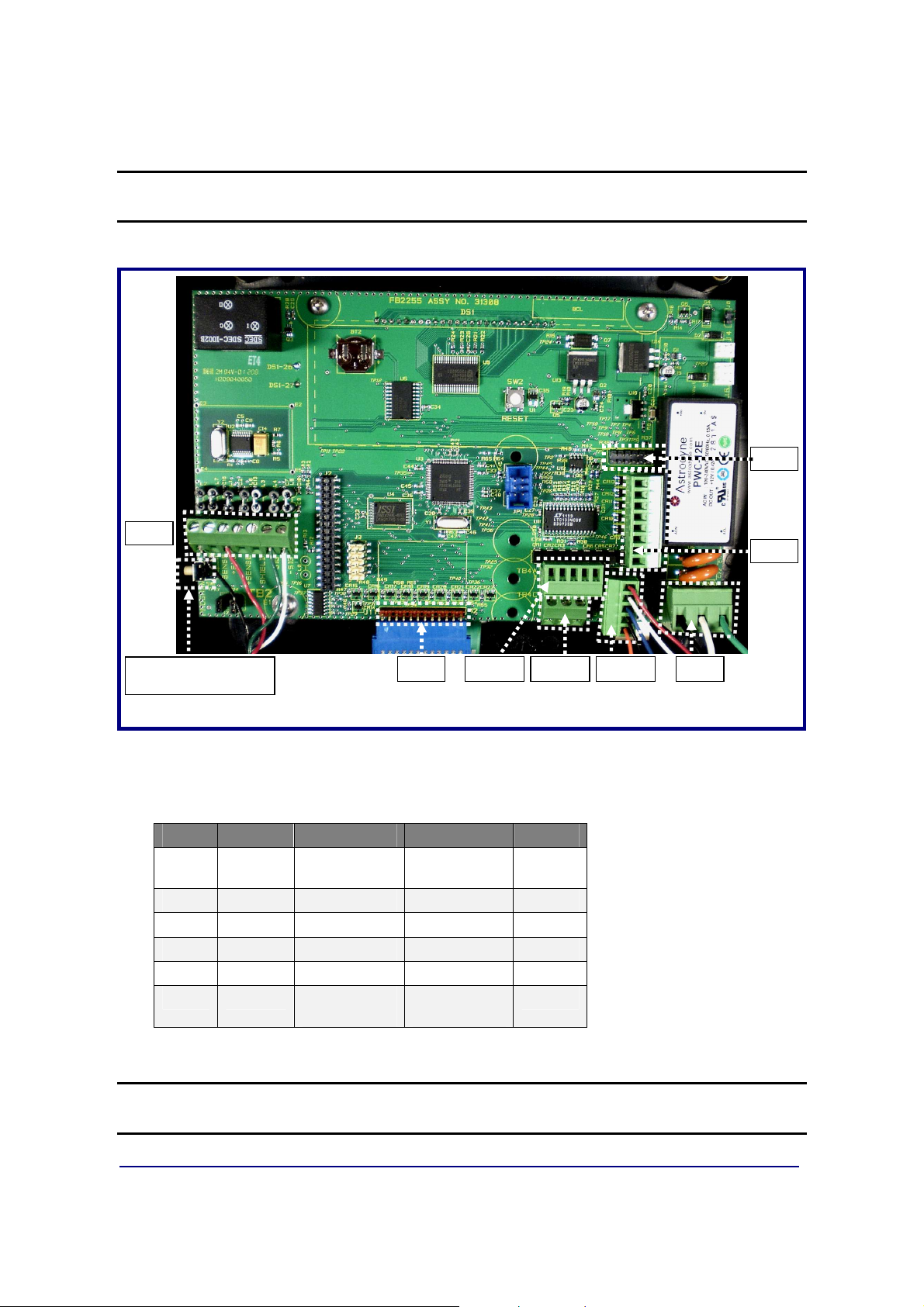
TB2
J11 TB4-A TB4-C TB4-B TB3
SWITCH
TB5
JP3
Section 3: Serial Communication Wiring
INTERNAL PROGRAM
Printed Circuit Board (31308)
3.1. JP3 Jumper Configuration)
JP3 RS232 RS485 RS422* PORT
1-2
3-4
5-6
7-8
9-10
11-12
*Port should be set to RS485.
Out 120 Ohm
Out In Out COM1
Out In Out COM1
Out In Out COM2
Out In Out COM2
Out 120 Ohm
Resistor
Resistor
120 Ohm
Resistor
120 Ohm
Resistor
COM1
COM2
NOTE: 120 ohm Termination Resistors
last node on the network.
01/13
22 51297 Rev. 1
are required if the receiver is the
Page 23
Section 3: Serial Communication Wiring
3.2. TB4 Wiring connections, COM1 (A), COM2 (B), and COM2 (C)
TB4 (A) RS232 RS485 RS422* PORT
1 Rx – Receive Data (–) RS485 RS422 (–) Rx COM1
2 Tx – Transmit Data (–) RS485 RS422 (–) Tx COM1
3 CTS – Clear-to-Send (+) RS485 RS422 (+) RX COM1
4 GND -- Ground GND GND COM1
5 RTS – Ready-to-Send (+) RS485 RS422 (+) Tx COM1
TB4 (B) RS232 RS485 RS422* PORT
1 Rx – Receive Data (–) RS485 RS422 (–) Rx COM2
2 TX – Transmit Data (–) RS485 RS422 (–) Tx COM2
3 CTS – Clear-to-Send (+) RS485 RS422 (+) Rx COM2
4 GND – Ground GND GND COM2
5 RTS – Ready-to-Send RS485 RS422 (+) Tx COM2
TB4 (C) 20 MA RS485 RS422 PORT
1 (+) TX – Remote Display
Passive, 20 mA Output
2 (–) TX – Remote Display
Passive, 20 mA Output
3
*Port should be set to RS485.
(+) 7.5V Bluetooth® Technology Supply
COM2
COM2
3.3. TB5 Remote Switch Inputs
1 Ground
2 Ground
3 Ground
4 Print Connect to ground to perform programmed Print function
5 Tare Connect to ground to Tare off Gross weight
6 B/G Net Connect to ground to Select Gross/Tare displays
7 Zero Connect to ground to Zero Platform Weight
8 Units Connect to ground to change to alternate weight units
01/13
23 51297 Rev. 1
Page 24

Section 3: Serial Communication Wiring
3.4. Remote Display Active Keys
INSTRUMENT FB2255 ACTIVE FRONT PANEL KEYS
FB2200
FB2255
FB2255
2300
2500
2800
5200A
01/13
24 51297 Rev. 1
Page 25

1
2
3
4
5
6
7
8
X
X
X
X
X
X
X
X
DS2 ON
OFF
1
2
3
4
5
6
7
8
9
10
X
X
X
X
X
X
X
X
X
X
DS1 ON
OFF
Section 4: Input / Output
4.1. 3550 Tape Printer
Transmission
Baud Rate
Data Bits
Stop Bit
OUTPUT
RS232
9600
8
1
“BUTTON” for Print Key
4.2. Okidata 186 T Form Printer
FB
Printer Cable (
15599
) is used for both printers.
Transmission
Baud Rate
Data Bits
Stop Bit
OUTPUT
RS232
9600
8
1
“BUTTON” for Print Key
Switch 7 (SW2)
** Space after power on ON
Space when printer is selected
Switch 8 (SW2)
01/13
DTR Signal
OFF
Not Used
25 51297 Rev. 1
Page 26

Section 4: Input / Output
4.2. Okidata 186 T Form Printer, Continued
Follow these steps to change Menu Settings.
1. To enter MENU MODE, press and hold
– The “12” and “UTILITY” LEDs will blink.
2. With the printer in the Menu Mode, press
– The current default settings print out.
– It is recommended to use tractor fed paper.
NOTE:
3. Press
4. Press
5. Press
6. To continue making changes: press
The Printed Menu selections are different for each
LINE FEED
– The group is the left-hand column on the Menu Printout.
FORM FEED
– The Item is the center column on the Menu Printout.
TOF SET
– The settings are the right-hand column on the Menu Printout.
FORM FEED
to select the relevant group to be changed.
to select the relevant item within the selected group.
to cycle through the settings available for the item to change.
for the next item.
SELECT
SELECT
LINE FEED
while turning on the printer.
to print the complete menu.
Emulation Mode.
for the next group or press
– Repeat as needed until finished changing settings.
7. Press
Mode.
NOTES:
changed settings.
01/13
PITCH
Exiting the
and
MODE
together to save the changes and exit the Menu
Menu Mode
by turning off the printer will cancel any
26 51297 Rev. 1
Page 27

Section 4: Input / Output
4.2. Okidata 186 T Form Printer, Continued
• Printed menu’s changes according to the Printer Emulation Mode.
• If printer emulation mode is not set to ML, set this first, then reprint the menu.
GROUP ITEM SET
(Press
to change) to change) to change)
Printer Control Emulation Mode ML
Font Print Mode Utility
Font DRAFT Mode SSD
Font Pitch 10 CPI
Font Proportional Spacing No
Font Style Normal
Font Size Single
Symbol Sets Character Set Standard
Symbol Sets Language Set American
Symbol Sets Zero Character Slashed
Symbol Sets Code Page USA
Vertical Control Line Spacing 6 LPI
Vertical Control Skip Over Perforation No
Vertical Control Page Length 11”
Set-Up Graphics Bi-directional
Set-Up 7 or 8 Bits Graphics 7
Set-Up Receive Buffer Size 128K
Set-Up Paper Out Override No
Set-Up Paper Registration 0
Set-Up 7 or 8 Bits Data Word 8
Set-Up Operator Panel Function Full Operation
Set-Up Reset Inhibit No
Set-Up Print Suppress Effective Yes
Set-Up Auto LF No
Set-Up Print DEL Code Yes
Set-Up Time Out Print Invalid
Set-Up Auto Select No
Set-Up Impact Mode Normal
LINE FEED
(Press
FORM FEED
(Press
TOF SET
01/13
27 51297 Rev. 1
Page 28

Section 4: Input / Output
4.2. Okidata 186 T Form Printer, Continued
GROUP ITEM SET
Parallel I/F I-Prime Buffer Print
Parallel I/F Pin 18 +5v
Parallel I/F Bi-Direction Enable
Serial PCB Assy Switch Settings: (SW1) (** indicates typical Fairbanks setting)
Parity Type Switch 1 (SW1)
** Odd parity ON
Even parity OFF
Parity Switch 2 (SW1)
** No parity ON
With parity OFF
Data Bits Switch 3 (SW1)
** 8 Bits ON
7 Bits OFF
Protocol Switch 4 (SW1)
Ready/Busy ON
** X-ON, X-OFF OFF
Test Select Switch 5 (SW1)
** Circuit ON
Monitor OFF
Mode Select Switch 6 (SW1)
** Print mode ON
Test mode OFF
Busy Line Selection Switch 7, 8 (SW1)
SSD- Pin 11 OFF, ON
SSD+ Pin 11 OFF, OFF
** DTR- Pin 20 ON, ON
RTS- Pin 4 ON, OFF
(SW2) (** indicates typical Fairbanks setting)
01/13
28 51297 Rev. 1
Page 29

Section 4: Input / Output
4.2. Okidata 186 T Form Printer, Continued
Transmission Speed Switches 1, 2, 3 (SW2)
19,200 bps ON, ON, ON
** 9,600 bps OFF, ON, ON
4,800 bps ON, OFF, ON
2,400 bps OFF, OFF, ON
1,200 bps ON, ON, OFF
600 bps OFF, ON, OFF
300 bps ON, OFF, OFF
110 bps OFF, OFF, OFF
DSR Input Signal Switch 4 (SW2)
Active ON
** Inactive OFF
Buffer Threshold Switch 5 (SW2)
32 bytes ON
** 256 bytes OFF
Busy Signal Timing Switch 6 (SW2)
** 200 ms minimum ON
1 second minimum OFF
01/13
29 51297 Rev. 1
Page 30

Section 4: Input / Output
4.3. Okidata 420 Form Printer
Program the FB2255 the following settings.
Transmission
Baud Rate
Data Bits
Stop Bit
OUTPUT
NOTE:
Always restart the printer after making any switch changes.
SEL
SEL
MENU
EXIT
POWER
1. To enter MENU MODE, press and hold the
SELECT
RS232
9600
8
1
“BUTTON” for Print Key
SHIFT
ALARM
LF
Micro Feed
Down
GROUP
FF/LOAD
Micro Feed
ITEM
key.
Up
MENU
TEAR
SET
FB
Printer Cable (
PARK
PRINT
SHIFT
key while pressing the
QUIET
TOF
15599
) is used for this printer.
– The MENU legend will be illuminated while in the Menu Mode.
2. With the printer in the Menu Mode, press
PRINT
to print the complete menu.
– The current default settings print out.
– It is recommended to use tractor fed paper.
NOTE:
3. Press
The Printed Menu selections are different for each Emulation Mode.
GROUP
to select the relevant group that needs to be changed.
– Found on the left-hand column on the Menu Printout.
4. Press
ITEM
to select the relevant item within the selected group.
– Found on the Item is the center column on the Menu Printout.
5. Press
SET
to cycle through the settings available for the item to change.
– The settings are the right-hand column on the Menu Printout.
6. Press and hold the
SHIFT
key while pressing the
SELECT
Menu Mode.
key to exit the
01/13
30 51297 Rev. 1
Page 31

Section 4: Input / Output
4.3. Okidata 420 Form Printer, Continued
NOTE:
be lost.
If the printer is turned off before exiting the
MENU MODE
, all changes will
GROUP ITEM SET
(Press
to change) to change) to change)
Printer Control Emulation Mode IBM PPR
Font Print Mode Utility
Font DRAFT Mode HSD
Font Pitch 10 CPI
Font Proportional Spacing No
Font Style Normal
Font Size Single
Symbol Sets Character Set Set 1
Symbol Sets Language Set American
Symbol Sets Zero Character Slashed
Symbol Sets Code Page USA
Rear Feed Line Spacing 6 LPI
Rear Feed Form Tear-off Off
Rear Feed Skip Over Perforation No
Rear Feed Page Length 11”
Bottom Feed Line Spacing 6 LPI
Bottom Feed Form Tear-off Off
Bottom Feed Skip Over Perforation No
Bottom Feed Page Length 11”
Top Feed Line Spacing 6 LPI
Top Feed Form Tear-off Off
Top Feed Skip Over Perforation No
Top Feed Page Length 11”
LINE FEED
(Press
FORM FEED
(Press
TOF SET
01/13
31 51297 Rev. 1
Page 32

Section 4: Input / Output
4.3. Okidata 420 Form Printer, Continued
GROUP ITEM SET
Set-Up Graphics Uni-directional
Set-Up Receive Buffer Size 64K
Set-Up Paper Out Override No
Set-Up Print Registration 0
Set-Up Operator Panel Function Full Operation
Set-Up Reset Inhibit No
Set-Up Print Suppress Effective Yes
Set-Up Auto LF No
Set-Up Auto Select No
Set-Up SI Select Pitch (10CP) 17.1 CPI
Set-Up SI Select Pitch (12CPI) 12 CPI
Set-Up Time Out Print valid
Set-Up Auto Select No
Set-Up Centering Position DEFAULT
Set-Up ESC SI Pitch 17.1 CPI
Set-Up Power Saving Enable
Set-Up Power Save Time 5 Min
Parallel I/F I-Prime Buffer Print
Parallel I/F Pin 18 +5v
Parallel I/F Bi-Direction Enable
Serial I/F Parity None
Serial I/F Serial Data 7/8 Bits 8 Bits
Serial I/F Protocol X-On/X-Off
Serial I/F Diagnostic Test No
Serial I/F Busy Line SSDSerial I/F Baud Rate 9600 BPS
Serial I/F DSR Signal Invalid
Serial I/F DTR Signal Ready on Pwr up
Serial I/F Busy Time 200 ms
01/13
32 51297 Rev. 1
Page 33

Section 4: Input / Output
4.4. TM-U295 Ticket Printer
Transmission
Baud Rate
Data Bits
Stop Bit
OUTPUT
RS232
9600
8
1
“BUTTON” for Print Key
Set the dip switches to the following.
• 1 and 3 are ON.
• The rest are
OFF
.
NOTE:
Always restart the printer after making any switch changes.
FB
Printer Cable (
15599
) is used for both printers.
4.5. TM-U590 Ticket Printer
Transmission
Baud Rate
Data Bits
Stop Bit
OUTPUT
Set the dip switches to the following.
• DSW 1
• DSW 2
RS232
9600
8
1
“BUTTON” for Print Key
• 1, 3 and 7 are
• All are
OFF
.
ON
only.
01/13
33 51297 Rev. 1
Page 34

Section 4: Input / Output
4.6. Remote Display
=CENTER OF ZERO
Part #
20903
Using the
20 mA Serial Current Loop Output
distances up to 1000 cable feet.
– Interface Cable (
20903
) is recommended.
Port
Baud Rate
Parity
Stop Bit
Current
2
C-Loop
2400
Odd
1
Passive
will allow transmission
The remote display must be wired for
20 mA Active
, and programmed to match
the FB2255.
– Wiring to the FB2255:
1 Tx + Passive 20 mA Output
2 Tx – Passive 20 mA Output
TB4 (C)
to the Remote Display.
Wire the Remote Display to the FB2255 as shown in this diagram.
(C)
(C)
01/13
34 51297 Rev. 1
Page 35

Section 4: Input / Output
4.6.1. PROGRAMMING THE 4-20MA ANALOG OUTPUT MODE
Access to this features is conditional, and depends upon whether it is enabled in the
FB2255 Internal Programming.
1. Press and hold the
NOTE
to
analog output continues to operate.
2. Select
3. Press
4. Press the
5. Press
Available selections include the following.
• Gross • Net
: If 4-20mA Analog Output has been installed and programmed, setting 4-20
NO
in the APPS Menu will prevent access to it from the front panel while the
GROSS
– The 4-20 mA Analog Output will continue to track the selection regardless of
the currently selected Weigh Mode.
MENU
right arrow
ENTER
UNITS
or
NET
.
to select an option.
key for three (3) seconds
.
key to toggle the available settings.
4.6.2. PROGRAMMING THE 4mA WEIGHT VALUE
4.20 Lo displays, followed by the current setting.
1. Key in the correct Weight Value with the
2. Press
This weight entry results in a
ENTER.
4mA Output
0-9
.
keys.
4.6.3. PROGRAMMING THE 20mA WEIGHT VALUE
4.20 Hi displays, followed by the current setting.
3. Key in the correct Weight Value with the
4. Press
This weight entry results in a
01/13
ENTER.
20mA Output
0-9
keys.
.
35 51297 Rev. 1
Page 36

Section 5: Fieldbus/Bluetooth
5.1. Fieldbus Installation
Fieldbus
system that interconnects measurement and control equipment such as sensors,
actuators and controllers.
– Fieldbus traces its beginnings in the automotive industry, where efforts to
For example, many cars have multiple controls on the door, such as power-window,
power-mirror, power-lock and power-seat controls.
– To eliminate the thick bundle of wires of the older method, a driver's-door
– If the driver presses the window switch, the door module closes a relay that
– If the driver presses the switch to adjust the passenger-side mirror, the
– This packet tells a different module to energize one of the power-mirror
As time has progressed, many different Fieldbus types have been developed, each
with different characteristics and specifications.
is a general term that describes an all-digital two-way communications
simplify and reduce wiring resulted in a multiplexed Controller Area Network
(CAN) system of modules installed at various points of a car
module monitors all of the switches.
provides power to the window motor.
driver's door module sends a packet of data onto the communication bus of
the car.
motors. In this way, most of the signals that leave the driver's door are
consolidated onto the two wires that form the communication bus.
– Very simply, they serve as a Local Area Network (LAN) for instrumentation
used in automatic process control and manufacturing applications.
– The LAN is a digital, bi-directional, multi-drop, serial-bus communications
network used to link field devices (often referred to as “Nodes”), such as
controllers, transducers, actuators and sensors.
There are a number of different manufacturers that produce Fieldbus devices.
– Each produces different hardware interfaces, wiring and connector types,
speed, and the amount of bytes of data that can be exchanged on the
network, among other things.
01/13
36 51297 Rev. 1
Page 37
Section 6: Fieldbus/Bluetooth
Additionally, the current Fieldbus communications network is replacing the older 420mA Analog Signal.
– The older 4-20 mA analog signal requires each device to have its own set of
wires and its own connection points.
– A Fieldbus eliminates this need as, generally, twisted pair wiring is used.
– All devices on the network are now connected together.
Fairbanks Scales currently offers three different Fieldbus Devices: DeviceNet™,
ControlNet™, Profibus®, and Ethernet/IP.
For more information and EDS files, see http://www.hms.se/default.shtml.
5.2. Fieldbus Connections
The term
system that interconnects measurement and control equipment such as sensors,
actuators and controllers.
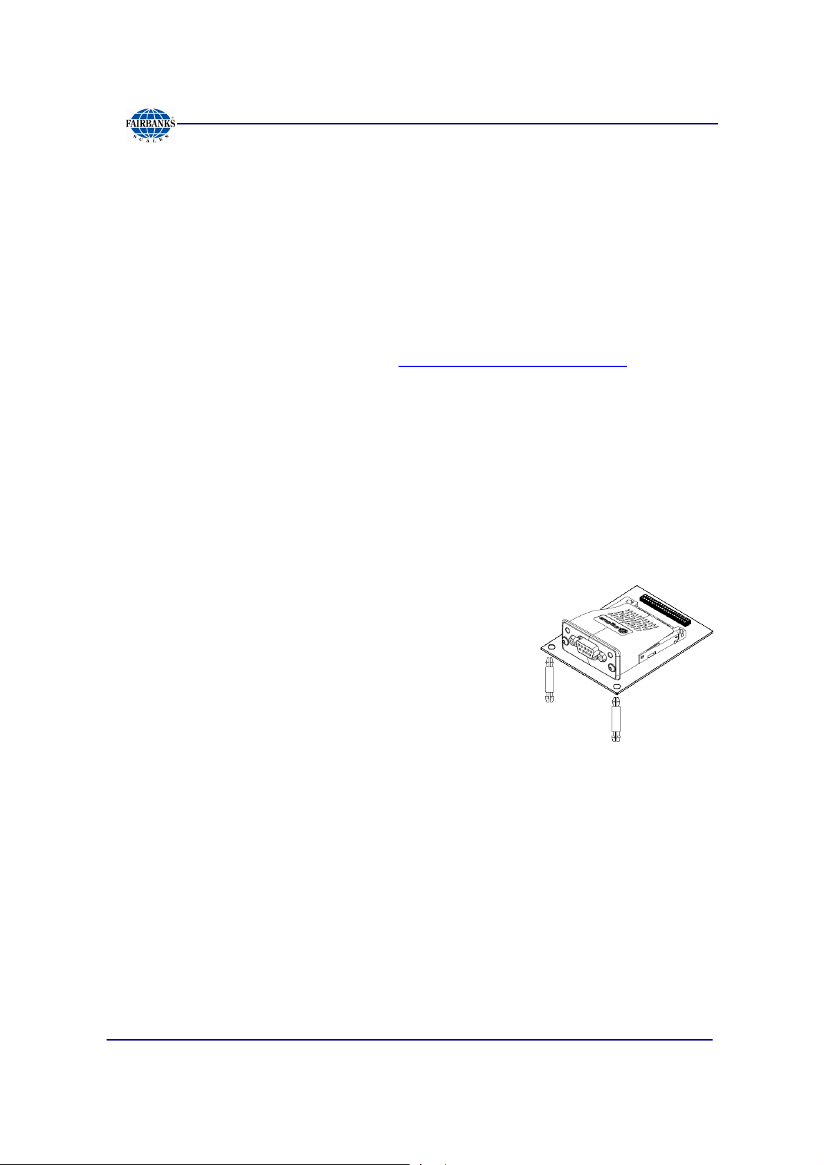
The Fieldbus assembly connects to the 32-pin header on the FB2255 main PCB
Assembly.
It is provided with two (2) standoffs which support the
right side of the card.
FIELDBUS
usually describes an all-digital two-way communications
5.2.1. OVERVIEW OF TERMS
There are currently four (4) different of Fieldbus Interfaces listed as standard
accessories for the FB2550 Instrument.
• DEVICE NET™ (29578)
– A network system to interconnect control devices for data exchange.
– It uses a differential serial bus, called Controller Area Network (CAN), as
the backbone technology and defines an application layer to cover a range of
device profiles.
• CONTROL NET® (31979)
– An open control network in real-time, for high-throughput applications.
01/13
37 51297 Rev. 1
Page 38

Section 6: Fieldbus/Bluetooth
5.2.1. OVERVIEW OF TERMS, CONTINUED
• PROFIBUS® (29576)
– Non-powered two-wire (RS485) network, with up to 126 nodes, transferring a
maximum of 244 data bytes per node per cycle.
• ETHERNET/IP (29873)
– Dynamic Host Configuration Protocol (DHCP) is used for address requests.
– The data is transmitted continuously from this module.
– The IP address may be made static by downloading the IP Configuration
Tool Software.
ETHERNET/IP
the Internet Protocol. Instead, it is an Industrial Application Layer Protocol used
for communication between industrial control systems and their components.
– Such components include Programmable Automation Controller, Logic
Controller, or an I/O System.
The “IP” in EtherNet/IP is not an abbreviation for “Internet Protocol”, but instead, it
stands for “Industrial Protocol”.
can be easily confused as a simple combination of EtherNet and
01/13
38 51297 Rev. 1
Page 39

Section 6: Fieldbus/Bluetooth
5.2.2. DEVICENET (29578)
DEVICENET
is a low-cost communications link that connects industrial devices to
a network, eliminating expensive hardwiring.
– It is based on a broadcast-oriented, communications protocol the CAN.
– The CAN Protocol was originally developed by BOSCH for the European
automotive market for replacing expensive wire harnesses with low-cost
network cable.
– The CAN Protocol has fast response and high reliability for applications like
anti-lock brakes and air bags.
DEVICENET
also provides power to the network. This allows devices with limited
power requirements to be powered directly from the network.
– This reduces connection points and physical size.
– The maximum network size is up to 64 Nodes, with message data packets up
to 8 bytes.
Wire
1
2
3
4
5
SIGNAL DESCRIPTION
V
CAN_L
SHIELD
CAN_H
V+
Negative bus supply voltage
CAN low bus line
Cable shield
CAN high bus line
Positive bus supply voltage
NOTE:
Additional information and
EDS files
are available at the following website.
http://www.hms.se/products/devicenet.shtml.
01/13
39 51297 Rev. 1
Page 40

Section 6: Fieldbus/Bluetooth
5.2.2. DEVICENET (29578), CONTINUED
NETWORK STATUS LED
STATE INDICATION
OFF
GREEN
FLASHING GREEN (1 Hz)
Red
Flashing Red (1 Hz)
Alternating Red/Green
Not online/ No power
Online, one or more connection established
Online, no corrections established
Critical link failure
One or more connections timed out
Self-test
1 NS = Operation Mode LED
2 MS = Mode Status LED
3 Connection = DeviceNet Connector
MODULE STATUS LED
STATE INDICATION
OFF
GREEN
FLASHING GREEN (1 Hz)
Red
Flashing Red (1 Hz)
Alternating Red/Green
No power
Operating in normal condition
Missing/Incomplete configuration/ Device needs commissioning
Unrecovrerable fault(s)
Recoverale fault(s)
Self-test
01/13
40 51297 Rev. 1
Page 41

Section 6: Fieldbus/Bluetooth
5.2.3. CONTROLNET (31979)
CONTROLNET
running in “real-time”, for high-throughput
applications.
– It uses a Control and Information Protocol
(CIP), combining the functionality of an I/O
Network and a Peer-to-Peer Network.
–
CONTROLNET
Producer/Consumer Model, permitting all
nodes on the network to simultaneously
access the same data from a single source.
– Maximum of 99 nodes, with no minimum
distance between nodes
– The Control net card uses BNC connectors.
is an open control network
is based on the
SPECIAL NOTES
For signal redundancy, both connectors should be used.
– If not, use either Connector A or B.
Network Status LED A and Module Status LED correspond to LED 1 and LED 2 in
the instance attributes of the Anybus Object.
– They are available in the application interface, but the LED placement on the
front does not conform to the standard Anybus CompactCom placement of
LED 1 and LED 2.
01/13
41 51297 Rev. 1
Page 42

Section 6: Fieldbus/Bluetooth
5.2.3. CONTROLNET (31979), CONTINUED
NETWORK STATUS
LED STATE INDICATION
A and B
A or B
OFF
Flashing Red (1 Hz)
Alternating Red/Green
Red
OFF
Alternating Red/Green
Flashing Green (1 Hz)
Green
Flashing Red (1 Hz)
Not online / No power
Incorrect node configuration, duplicate MAC ID etc.
Self test of bus controller
Fatal event or faulty unit
Channel is disabled
Invalid link configuration
Temporary errors (node self-corrects) or node is not
configured to go online.
Normal operation
Media fault or no other nodes on the Network
MODULE STATUS
STATE INDICATION
OFF
GREEN Operating in normal condition, controlled by a Scanner in RUN state.
FLASHING GREEN
(1 Hz)
Red
Flashing Red (1
Hz)
No power
The module has not been configured or the Scanner is in the Idle state.
Unrecovrerable fault(s), EXCEPTION,
Media fault or no other nodes on the Network
No.
1
2 Module Status LED
3
4
5
DESCRIPTION
Network Status LED A
Network Status LED B
ControlNet Connector A
ControlNet Connector B
01/13
42 51297 Rev. 1
Page 43

Section 6: Fieldbus/Bluetooth
5.2.4. PROFIBUS (29576)
PROFIBUS
is one of the best-known industrial
fieldBus protocols from Europe.
– It is an established standard, used in a wide
range of applications as a multi-application
communications link for industrial devices.
– The ProfiBus protocol was originally
developed by a committee founded by the
German government.
PROFIBUS
utilizes a non-powered two-wire (RS-485) Network.
– A ProfiBus Network may have up to 126 nodes, transferring a maximum of
244 bytes data per node/ per cycle.
– Baud (Communication) Rates are selectable, and overall end-to-end network
distance varies with speed.
– The maximum standard Baud Rate is 12Mbps, with a maximum distance of
100M (328ft), and 1200M (3936 ft.) at 93.75Kbps without repeaters.
–
PROFIBUS
connects to a wide variety of field devices including the
following:
▪ Discrete and analog I/O Drives.
▪ Robots.
▪ HMI/MMI products.
▪ Pneumatic valves.
▪ Barcode readers.
▪ Weigh scales.
▪ Transducers.
▪ Flow measuring equipment.
PIN SIGNAL DESCRIPTION
3
4
5
6
8
B-Line
RTS
GND
+5 Bus
Output
A-Line
Positive RxxD/TxD, Rs485 level
Request to Send
Ground (Isolated)
+5V termination power (Isolated,
short circuit protected)
Negative RXD/TxD, RS485 level
01/13
43 51297 Rev. 1
Page 44

Section 6: Fieldbus/Bluetooth
5.2.4. PROFIBUS (29576), CONTINUED
OPERATION MODE LED
LED STATE DESCRIPTION
OFF
Green
Flashing Green
Flashing Red (1 flash)
Flashing Red (2 flashes)
Not online or No power
Online/ Data Exchange
Online, clear
Parameterization error
Profibus configuration error
MODULAR STATUS LED
LED STATE DESCRIPTION COMMENTS
OFF
Green
Flashing Green
Red
No power - OR – not initialized
Initialized
Initialized, diagnostic events(s) present Extended diagnostic bit is set
Exception error
Module state = “SETUP” OR NW-INIT”
Module has left the NW_INIT state
Module state = EXCEPTION
NO. DESCRIPTION
1 Communication
LED
2 Device Status LED
3 Profibus Interface
NOTE:
Additional information and
EDS files
http://www.hms.se/default.shtm.
01/13
are available at the following website.
44 51297 Rev. 1
Page 45

Section 6: Fieldbus/Bluetooth
5.2.5. ETHERNET / IP DIAGNOSTIC LEDS
The Ethernet/IP module uses Dynamic Addressing.
– Dynamic Host Configuration Protocol
(DHCP) is used for address requests.
– The data is transmitted continuously from this
module.
– The IP address may be made static by
downloading the IP Configuration Tool
Software from the following site:
http://www.hms.se/support/support.asp?PID=368&Product
Type=Anybus-CompactCom.
• Using this download, it is possible to change the IP, Sub Net and Gateway
addresses of an Ethernet/IP Module.
• To change an address, double click on the IP address field and enter the
changes.
Shown below is the Network Status LED Chart
1. Network Status LED
2. Module Status LED
3. Link/Activity
4. Ethernet Interface (RJ-45)
(Standard Cat 5 Cable)
STATE DESCRIPTION
Off Not online / No power
Green Online, one or more connections established.
Flashing Online, no connections established
Red Duplicate IP address, FATAL error
Flashing Red One or more connections timed out
Shown below is the Module Status LED Chart
STATE DESCRIPTION
Off No power
Green Controlled by a scanner in Run state
Flashing Green Not configures, or Scanner in idle state
Red Major fault (EXCEPTION-state, FATAL error, etc.)
Flashing Red Recoverable fault(s)
Shown below is the Link / Activity LED Chart
STATE DESCRIPTION
Off No link, no activity
Green Link established
Flickering Green Activity
For more information and EDS files, see http://www.hms.se/default.shtml.
01/13
45 51297 Rev. 1
Page 46

Section 6: Fieldbus/Bluetooth
5.3. Bluetooth® Technology Device
The Bluetooth® Option replaces direct wiring
between two devices.
– The Bluetooth® Interface uses either
Port 1
– RS232 Serial Interface to Bluetooth®
Interface with a range of 100 meters
(328 feet).
The Bluetooth® Option operates either as a
Client or Server, depending on its
connecting device.
If its connected to a printer, the FB2255 will
be a Server. If connected to a PC, it is a
Client.
or
Port 2 Serial Output
.
Shown below are some Bluetooth® products with their features.
MODEL NO. MODEL NAME DESCRIPTION
29515 Bluetooth® Accessory, Class I, for
non-FB2255 device
29639
29516 Bluetooth® Accessory, Class I,
AC Power adapter for Bluetooth
Accessory 29215
FB2255
• Power source required for non-FB2255
side of the connection.
• 5 - 12 VDC, USB power cable provided.
• PC interfacing software provided.
®
• For use if USB power cable not
applicable.
• FB2255 provides power
• RoHS compliant
• Includes cable
29402
The Bluetooth® device is supplied with a DB-9 female connector.
Shown below is the wiring code / color code to connect the FB2255 and the
Bluetooth® Device.
FB2255 TB 4
Pin 1 Pin 2 Red
Pin 2 Pin 3 White
Pin 4 Pin 5 Black
Pin 13 Pin 9 Green
BLUETOOTH®
DEVICE
FB SUPPLIED
CABLE
01/13
46 51297 Rev. 1
Page 47

Section 6: Fieldbus/Bluetooth
5.3. Bluetooth® Technology Device, Continued
Set the 4-position Dip Switch on each device as shown below.
1,2,3
4
ON
OFF
Follow these steps to installing the Bluetooth® Devices.
5. Turn on both Bluetooth® Devices with the
SLIDE SWITCH
6. Press the
7. Press the
RESET BUTTON
PAIRING BUTTON
on their sides.
on each one.
of Device #1
for two (2) seconds
– The Standby LED turns
OFF
.
– The Connect LED blinks three (3) times
every two (2) seconds.
– Keep the power
8. Press the
PAIRING BUTTON
ON
.
of Device #2
for two (2) seconds.
Baud Rate
Data Bits
Parity
Stop Bit
9600
8
None
1
– The Standby LED turns
OFF.
– The Connect LED blinks three (3) times every two (2) seconds.
9. Press the Pairing Button again for two (2) seconds until the Connect LED blinks
every half (½) second.
• Wait for Devices #1 and #2 to connect to
each other.
– The Connect LEDs of both will be
solid green.
– This connection process takes about
ten (10) seconds.
– If any other Bluetooth® devices are
nearby, it may take longer.
01/13
47 51297 Rev. 1
Page 48

Section 6: Fieldbus/Bluetooth
5.3. Bluetooth® Technology Device, Continued
10. Turn Device #1
– The Connect LED light blinks green twice every three (3) seconds.
11. Turn Device #2
12. The Connect LED light blinks green once every second.
Configuration is now complete. Both devices are configured to make automatic
connection to each other whenever they are powered on.
OFF,
OFF,
and then back
and then back
ON
ON
.
.
01/13
48 51297 Rev. 1
Page 49
Section 6: PC2255 Utility Software
C A U T I O N
USING THIS PC2255 UTILITY PROGRAM CAN ALTER
PROPER CALIBRATION AND USER FUNCTIONS.
OWNER ASSUMES ALL RISKS WHILE USING THIS PROGRAM!
THE CUSTOMER WILL BE RESPONSIBLE FOR ALL
SERVICE DEPARTMENT COSTS TO RESTORE THE
INSTRUMENT TO ITS PROPER OPERATIONS.
6.1. Introduction
• The PC2255 utility software program can be used to set up and configure the
FB2255.
• It is required in order to program certain features, such as custom units and
custom ticket vector programming.
• The FB2255 uses
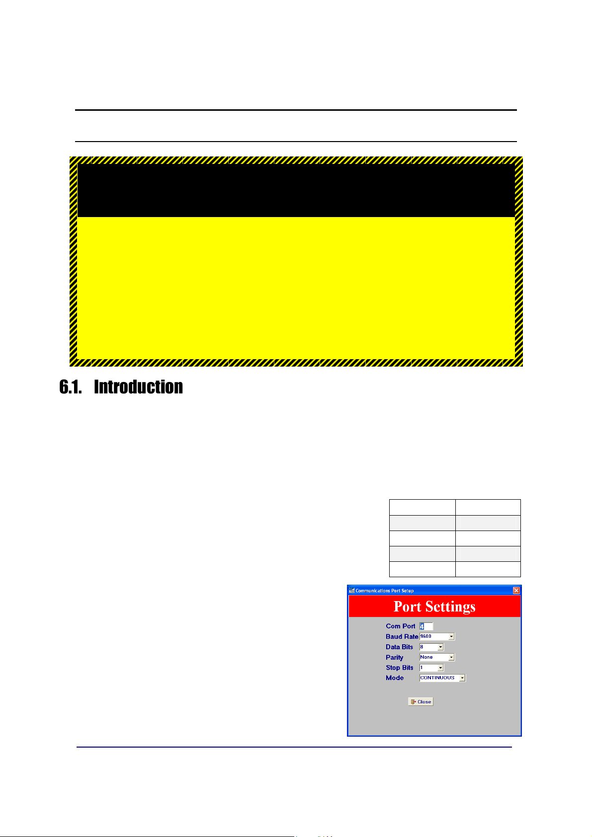
6.2. Communication Settings
1. Access the COM Port Settings of the computer by
pressing F2.
The Standard Defaults are noted in the chart to
the right.
Port 2
to communicate to the computer.
Baud Rate
Data Bits
Parity
Stop Bit
Mode
9600
8
None
1
Continuous
2. Set
3. Set the FB2255 Port 2 to the same settings,
01/13
VERSION
– It displays at the warm-up screen of the
Instrument.
and then exit from program mode.
setting to match the FB2255.
49 51297 Rev. 1
Page 50

Section 6: PC2255 Utility Software
6.2. Communication Settings, Continued
1. Launch the
– An image of the FB2255 will display on the computer monitor.
– The legend “CONNECTED” with a rotating baton will displayed.
– The weight display will duplicate what is shown on the FB2255.
2. Left-clicking the mouse on any key to transmit that command to the FB2255.
– This excludes the
– The legend “COMMAND SENT!” will display at the right.
– Mouse-clicking the
program.
PC2255.exe
PRINT key.
ON/OFF
file.
key will terminate the PC2255 software
01/13
50 51297 Rev. 1
Page 51
Section 6: PC2255 Utility Software
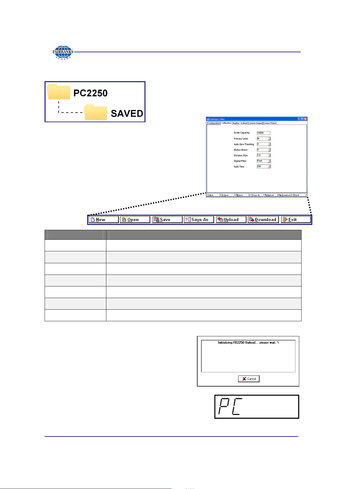
6.3. Communication Files
The default folder for all saved/uploaded
parameter files is
6.4. Menu Bar
The PC2255 menu bar is located at the bottom of
the display.
BUTTON FUNCTION
NEW
OPEN
SAVE
Loads the Parameters Menu with FB2255 default settings.
Opens the SAVED folder to select a file.
Saves the currently named file.
PC2255\SAVED.
SAVE AS
UPLOAD
DOWNLOAD
EXIT
1. Press the
current FB2255settings to the PC2255.
– The FB2255 displays “PC”.
2. Press the
SWITCH
01/13
UPLOAD
INTERNAL PROGRAMMING
.
Saves the current file and prompts for a file name.
Uploads the current FB2255 settings to the PC2255.
Downloads the current PC2255 settings to the FB2255.
Exits the program.
button to retrieve the
51 51297 Rev. 1
Page 52

Section 6: PC2255 Utility Software
6.4. Menu Bar, Continued
3. When the process is complete, click
4. Click the
the current PC2255 settings to the FB2255.
The FB2255 displays “PC”.
5. Press the
PROGRAMMING SWITCH.
DOWNLOAD
INTERNAL
button to retrieve
OK
.
6. When complete, click
7. Press
EXIT
to close the Parameter Editor.
OK
.
01/13
52 51297 Rev. 1
Page 53

Section 6: PC2255 Utility Software
6.5. Configuration
1. Press
Use one of the following methods that apply to programming the features.
• Click on the data item to highlight it, then type in the replacement data.
• Click the drop down arrow and selecting an available item.
F4
to enter the Parameters Editor.
• Click on the checkmark to select the option(s).
• Input the custom unit factor to set the conversion factor of the current primary
weight data.
CUSTOM UNIT PROGRAMMING EXAMPLE
To convert pounds to dry barrel units, enter the conversion factor, resolution and
custom legend. The current primary weight will be multiplied by the conversion
factor, rounded off to the custom resolution and printed with a custom legend.
01/13
53 51297 Rev. 1
Page 54
Section 6: PC2255 Utility Software
6.6. Calibration
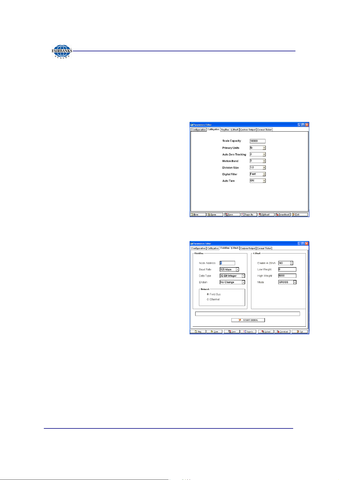
Settings from this window include the following options.
• Scale capacity • Primary Units • Auto Zero Tracking (AZT) • Motion Band (BAL)
• Division Size • Digital Filter • Auto Tare settings
Actual test weight calibration is performed with
the FB2255 front panel keys.
6.7. Fieldbus / 4-20 mA
The Anybus or DeviceNet Module is set up
using the
supported by the following parameters.
NODE ADDRESS
• Enter the Node Address of the Module.
• This is typically furnished by the customer.
BAUD RATE
• Most Anybus Modules can automatically detect the network speed by using the
Auto Baud feature.
• Device Net uses 125K bps, 250K bps or 500K bps.
PC2255 Program
and is
01/13
54 51297 Rev. 1
Page 55

Section 6: PC2255 Utility Software
6.7. Fieldbus / 4-20 mA, Continued
DATA TYPE
Data can be setup to output a 32 bit Integer
word or a 32 bit floating point value.
ENDIAN
The Endianess of a module is determined by
the network type, but can be changed from
Little Endian to Big Endian, or vice versa by
using the
LITTLE ENDIAN FORMAT OR INTEL ORDER
In Little Endian Format, the least significant byte is stored first, followed by the
next three more significant bytes.
"CHANGE ORDER"
setting.
For example, a 32bit value of
0x12345678
would be stored in memory in
LITTLE ENDIAN as shown below.
• Address + 0 0x78
• Address + 1 0x56
• Address + 2 0x34
• Address + 3 0x12
BIG ENDIAN FORMAT OR MOTOROLA ORDER
In Big Endian Format, the most significant byte is stored first, followed by the next
three least significant bytes.
For example, a 32bit value of
BIG ENDIAN as shown below.
• Address + 0 0x12
• Address + 1 0x34
0x12345678
would be stored in memory in
• Address + 2 0x56
• Address + 3 0x78
01/13
55 51297 Rev. 1
Page 56

Section 6: PC2255 Utility Software
6.7. Fieldbus / 4-20 mA, Continued
OUTPUT
Data from the FB2255 comprises of three (3) 32-bit words.
• Gross Weight
• Tare Weight
• A 32bit Status Word
• Gross and Tare weights can be selected as either a 32-bit Integer or a 32-bit
Floating Point Word.
• The Most significant Byte indicates the Weigh Mode
for Net.
• The Next Order Byte indicates
command received. (See INPUT Commands)
The next order byte indicates the weight units.
•
"l"
•
"k"
pounds
kilograms
"O"
Overcapacity,
"G"
for Gross, and
"M"
Motion of the last
"N"
•
"o"
ounces
•
"g"
grams.
The Least Significant Byte indicates the number of decimal places, if the weight
output is selected to be a 32-bit Integer word.
– If a Floating point word is selected, this byte will be
“0”.
INPUT
Single Byte Commands can be sent from the network.
– Although the input is read as a 32-bit word, only the Least Significant Byte is
used in this process.
– When the command is sent and recognized, it is entered into the 32 -bit status
byte in the Least Significant Command Byte location.
– New commands can be transmitted after transmitting a
NULL
command.
01/13
56 51297 Rev. 1
Page 57

Section 6: PC2255 Utility Software
6.7. Fieldbus / 4-20 mA, Continued
RECOGNIZED COMMANDS
COMMAND DESCRIPTION
Print Steam
Print Format Stream CR, SPACE, STX, ENQ or Defined Poll
Tare “A”
Print Ticket “p” or “P”
Zero “Z”
Change Gross Net
Weight Mode
Change Units “U”
See Custom Format PC2255.
Character
“G”
DEBUG
• Data in the Anybus Module can be examined by clicking the
button.
• It is stopped by clicking the
STOP DEBUG
button.
START DEBUG
• The
WRITE BUFFER
contains three 32-bit words.
– Gross Weight, Tare Weight and the Status Word is the data sent to the
Network.
• The Contents of the
READ BUFFER,
which is the data received from the
network, is displayed as a 32-bit word.
01/13
57 51297 Rev. 1
Page 58

Section 6: PC2255 Utility Software
6.8. Custom Output – Settings
CHECKSUM
• This setting determines whether a
Checksum Character is enabled or not.
• Checksum is an error detection method
that checks the integrity of the entire string
of data that is transmitted.
DELIMITED
This setting determines if a comma is added
to the output string to separate data fields
contained within the output string.
HARDWARE HAND SHAKING
No current function. Set up for future use.
6.9. Custom Output – Load
A variety of pre-packaged Output Strings is
available.
1. Click the radio button that applies.
Default = Fairbanks
2. Click
OK
Cancel
– See
Formats
to download the settings, or
.
Appendix 1: Data Output
.
IMPORTANT NOTE:
Customized Outputs use
The power must be cycled to the FB2255 Instrument whenever custom outputs are
programmed in order for them to take effect.
Port 1
only.
01/13
58 51297 Rev. 1
Page 59

Section 6: PC2255 Utility Software
6.10. Custom Output – Build
1. Customize the Data Output String to suit
the application requirements.
– The current structure of the output
string is displayed at the bottom of the
Custom Output page, in order of
transmission from left-to-right.
2. Right-click in the selected
field
– This opens a selection window
to change data items.
containing many different data items.
DATA TYPE
01/13
59 51297 Rev. 1
Page 60

Section 6: PC2255 Utility Software
6.11. Custom Output – Tokens
1. Select from a wide variety of different
characters for the polling character.
• Start • Stop
• Block • Primary Units
• Secondary Units • Weighing Mode
• Motion
2. When entering a character that is not listed,
select
• Capacity
Characters
USER DEFINED
.
This will produce an additional data entry box as shown.
3. Right-click in the selected
DATA ENTRY
BOX to change data items.
01/13
60 51297 Rev. 1
Page 61

Section 6: PC2255 Utility Software
6.11. Custom Output – Tokens, Continued
4. Make a selection, such as
<SOH>
, for
example.
– This inserts a Start of Header
character… otherwise known as a
CTRL/A, or 0x01 HEX.
5. When entering a character not listed, select
ENTRY
.
6. Select
ENTRY
to insert a character using
the keyboard, such as an A or a 1.
6.12. Custom Output – Weights
A variety of settings are available for the
Weight Digits window. These choices include
the following.
• Weight Digits • Leading Zeros
• Justification • Decimal Point
• Fixes Decimal
Places
• Include Polarity (checkbox)
• Positive Token • Negative Token
01/13
61 51297 Rev. 1
Page 62

Section 6: PC2255 Utility Software
6.13. Formatting Tickets
• Formatting tickets is easily performed with
this drag and drop interface.
• The blue-dashes indicate the printable area
of the ticket based on the ticket size and
margins entered (by the user or by default).
1. Click-and-hold on a data item to move it to a
different location.
2. Change the numeric values for
LEFT
– Legends such as GROSS cannot be disabled, and are always included.
3. Select
To S
– An example of this is Paper out.
4. Complete all the items can be disabled from view and
printing by right clicking the
selecting
5. Additional selections are available for both
and
.
INHIBIT
end) hardware handshake (
NO
COUNT 2
to set the status of the
or
YES
.
.
TOP
BUSY
VISIBLE
and
CTS (C
) lines.
box, and then
lear To Send) and
COUNT 1
RTS (R
eady
01/13
62 51297 Rev. 1
Page 63

Section 6: PC2255 Utility Software
6.14. Printed Examples
ACCUMULATION.
PIECE COUNT & TOTAL
Printing Time, Date, Gross, Tare, Net, Count 1, and Count 2.
PEAK WEIGHT
PIECE COUNT & TOTAL.
01/13
63 51297 Rev. 1
Page 64

Section 7: Service and Maintenance
7.1. Troubleshooting the Instrument
DISPLAY SYMPTOM RESOLUTION
ERROR
No Display No Power
Drifting/Unstable
• Possible bad battery or power loss
• Program error
• Display changes at a rapid pace.
• Loss of Excitation voltage.
• Replace the PCB.
• Replace Battery
• Check AC Input
• Check battery voltage
• Check for damaged load cell, load
cell cables, or bad main PC.
• Measure the Excitation Voltage
(5VDC)
• Use a Simulator to troubleshoot.
7.2. Battery Installation
STAINLESS STEEL ENCLOSURE
STAINLESS STEEL INSTRUMENT
6. Unscrew the black plastic end caps.
7. Insert five (5) alkaline “D” cell batteries.
ABS INSTRUMENT
8. Unscrew the two large knurled screws on the back of the Instrument
9. Remove the battery cover.
10. Insert five (5) alkaline “D” cell batteries.
• Industrial ‘D’ size Energizer EN95 battery or equivalent is recommended for
maximum operating time.
• Stainless Steel models should have special formed key washers installed for
grounding.
– Four (4) screws fasten the back cover plate at the corners.
ABS ENCLOSURE
01/13
64 51297 Rev. 1
Page 65

Appendix I: Data Output Formats
A. General Notes
<CR>
<LF>
<SP>
<EOT>
<…>
= means carriage return character
= line feed character
= space character
= end of transmission character
= used to indicate individual characters for clarity only (not present in
data stream)
B. Fairbanks/ Toledo Continuous Output
<STX><A><B><C><WWWWWW><TTTTTT><CR>
A
= Status Word A
B
= Status Word B
C
= Status Word C
W
= Displayed Weight
T
= Tare Weight
• Leading zeros are not suppressed.
• The Continuous Computer Output is an uninitiated, unrequested output that is
transmitted at a fixed time interval.
01/13
65 51297 Rev. 1
Page 66

Appendix 1: Data Output Formats
B. Fairbanks/ Toledo Continuous Output, Continued
Character String Description
STX Start of Text character : (02 Hex)
A Status Word A
B Status Word B
C Status Word C
xxxxxx Displayed Weight : x = Weight
(6 characters if grad size does not have a decimal point.)
(5 characters if the grad size does have a decimal point.
The decimal point is not sent as part of the character string.
xxxxxx Tare Value : x = Tare
(6 characters if the grad size does not have a decimal point.)
(5 characters if the grad size does have a decimal point.
The decimal point is not sent as part of the character string
CR Carriage Return Character : (0D hex)
CS CheckSum Character : If enabled, this character consists of the last
eight bits of the binary
sum of all characters transmitted up to this checksum character.
Status Word A
Bit # Decimal Point or Zero Location
x00 x0 x x.x x.xx x.xxx x.xxxx x.xxxxx
0 0 1 0 1 0 1 0 1
1 0 0 1 1 0 0 1 1
2 0 0 0 0 1 1 1 1
Increment Size
Count by 1 Count by 2 Count by 5
3 1 0 1
4 0 1 1
5 Always Logic 1
6 Always Logic 0
7 Parity Bit
01/13
66 51297 Rev. 1
Page 67

Appendix 1: Data Output Formats
B. Fairbanks/ Toledo Continuous Output, Continued
Status Word B
Bit # Description
0 Gross = 0 Net = 1
1 Positive = 0 Negative = 1
2 In Range = 0 Overcapacity = 1
3 No Motion = 0 Motion = 1
4 lb = 0 kg = 1
5 Always Logic 1
6 Normal = 0 Power Up = 1
7 Parity Bit
Status Word C
Bit # Description
0 Always Logic 0
1 Always Logic 0
2 Always Logic 0
3 Normal = 0 Print Switch Pushed = 1
4 Always Logic 0
5 Always Logic 1
6 Normal = 0 Keyboard Tare = 1
7 Parity Bit
01/13
67 51297 Rev. 1
Page 68

Appendix 1: Data Output Formats
C. Cardinal 738 Continuous Scoreboard Output
<CR><P><WWWWWW><m><SP><U><SP><g><SPSP><ETX>
W = Displayed weight
P = Polarity + = Positive weight
- = Negative weight
U = Units
lb = pounds
kg = kilograms
m = Motion or o = Overload
g = Gross; n = Net
SP = Space
Leading zeros are not suppressed
D. Weightronics WI-120 Continuous Output
<G><P><WWWWWW><SP><U><CR><LF>
G = Gross; N = Net
P = Polarity + = positive weight
- = negative weight
U = Units
lb = pounds
kg = kilograms
SP = Space
Leading zeros are not suppressed
01/13
68 51297 Rev. 1
Page 69

Appendix 1: Data Output Formats
E. Condec Continuous Output
<STX><P><WWWWWWW><U><G><M><CR>
P = Polarity space = positive weight
- = negative weight
W = Displayed weight
U = Units
L = pounds
K = kilograms
G = Gross; N = Net
M = Motion
Leading zeros are suppressed
F. Demand Output
Activated by the receipt of a <CR>.
Gross Weight – No Motion – decimal points included
<SP> <W> <W> <W> <W> <W> <W> <SP> <l> <b> <SP> <SP> <G>
<R> <SP> <SP> <CR> <LF> <EOT>
Gross Weight – Motion – decimal points included
<SP> <W> <W> <W> <W> <W> <W> <SP> <l> <b> <SP> <SP> <g>
<r> <SP> <SP> <CR> <LF> <EOT>
Net Weight – No Motion – decimal points included
<SP> <W> <W> <W> <W> <W> <W> <SP> <l> <b> <SP> <SP> <N>
<T> <SP> <SP> <CR> <LF> <EOT>
01/13
69 51297 Rev. 1
Page 70

Appendix 1: Data Output Formats
G. Continuous Output
• Outputs once every display update rate cycle.
• Continuous Output formatted output. Same for Poll and Auto
• Gross Weight – No Motion – decimal points included.
<SP> <W> <W> <W> <W> <W> <W> <SP> <l> <b> <SP> <SP> <G>
<R> <SP> <SP> <CR> <LF> <EOT>
Gross Weight – Motion – decimal points included
<SP> <W> <W> <W> <W> <W> <W> <SP> <l> <b> <SP> <SP> <g>
<r> <SP> <SP> <CR> <LF> <EOT>
Net Weight – No Motion – decimal points included
<SP> <W> <W> <W> <W> <W> <W> <SP> <l> <b> <SP> <SP> <N>
<T> <SP> <SP> <CR> <LF> <EOT>
Net Weight – Motion – decimal points included
<SP> <W> <W> <W> <W> <W> <W> <SP> <l> <b> <SP> <SP> <n>
<t> <SP> <SP> <CR> <LF> <EOT>
01/13
70 51297 Rev. 1
Page 71

Appendix 1: Data Output Formats
H. PLC
Baud Rate
• Continuous Output, transmitting data on every other
A/D update.
– Approximately 32 transmissions per second.
The output string is 12 characters, seen as “
Negative sign precedes most significant digit and may be preceded by space
characters.
Example 1: Gross – lbs. – Weight Stable
<wwwwwww>
<uu>
<mm>
<eot>
= units “lb”, “kg”, “oz”, or “g “. “oz” may indicate ounces, or lb/ounces.
= mode “GR” or “NT” for stable weight, or “gr” or “nt” for motion.
= end of text.
= Weight including decimal point and negative sign.
wwwwwwwuumm<eot>
Data Bits
Parity
Stop Bit
Mode
19,200
8
None
1
Continuous
” where,
<WWWWWWW> <l><b> <G> <R> <EOT>
Example 2: Gross – lbs. – Weight in Motion
<WWWWWWW> <l> <b> <g> <r><EOT>
Example 3: Net – kgs. – Weight Stable
<WWWWWWW> <k> <g> <N> <T> <EOT>
Example 4: Net – kgs. – Weight in Motion
<WWWWWWW> <k> <g> <n> <t> <EOT>
NOTE:
installing technician’s setup is complete.
Specialized tools available from www.anybus.com.
Once
PLC option
is selected and protocol has been programmed, the
Interface of the
device, and programming of the PLC is strictly the responsibility of the customer.
HMS COMMUNICATIONS
device, power supply to same
01/13
71 51297 Rev. 1
Page 72

Appendix 1: Data Output Formats
I. UPS
•
Serial Data Output Format
The instrument will transmit the following string of data.
Character Number 1 2 3 4 5 6 7 8 9 10 11 12 13 14 15 16 17 18
String 1
Gross Weight: X X X X . X X SP l/k b/g SP G/g R/r SP SP CR LF EOT
NOTES:
for UPS Worldship Software.
• Characters denoted by
– Leading zeroes are replaced with spaces (SP).
– Character 5 is a decimal point (HEX 2E).
• Lower case
Units.
• The first weight character will be a
• Characters separated with a
transmitted.
– Lower case gr in characters 12 and13 indicates scale motion.
– Upper case indicates stable weight.
•
EOT
, HEX 04 is transmitted in “HiCAP” condition.
• Transmission will occur when a
“I”
and
“X”
are characters 0-9.
“b”
for Avoirdupois Units, or
minus (–
“/”
denoted one of the characters will be
CR
(Hex 0D) carriage return is received.
“k”
and
), HEX 2D, If weight is negative.
“g”
for Metrics
01/13
72 51297 Rev. 1
Page 73

Appendix 1: Data Output Formats
J. P Ship
• Serial Data Output Format for P Ship, used to interface to FedEx Shipping
Programs.
• All computer commands and scale responses are ASCII Character Strings,
where:
<CR>
<LF>
<ETX>
(STATUS)
is an ASCII carriage return (hexadecimal 0D)
is an ASCII line feed (hexadecimal 0A)
is an ASCII End-Of-Text (hexadecimal 03)
is a two ASCII number representation of the scale status (in the form of
hexadecimal 3x3x, where the bit pattern of the low nibbles, indicated by an "x",
determine the actual status conditions)
COMPUTER
RESPONSE
W<CR>
S<CR>
Z<CR>
All Else
SCALE RESPONSE
<LF><SP>XXX.XXUU<CR>(STATUS)<ETX>
<LF>S(STATUS)<CR><ETX>
No response
<LF>?<CR>
COMMAND
RESULT
Returns the weight
and scale status in two
ASCII digits.
Returns the scale
Status in two ASCII
digits (defined in the
following section)
Zeros the scale
Unrecognizable
command
Notes: In the scale response to "W<CR>":
1
. XXX.XX
= A five digit number with two digits to the right of the decimal point
which is the displayed scale weight.
2
. SP
= An ASCII space (hexadecimal 20). In the event of a negative
weight, an ASCII, "-" (hexadecimal 2D) is returned in this
location.
01/13
73 51297 Rev. 1
Page 74

Appendix 1: Data Output Formats
J. P Ship, Continued
3. UU = A two character weight identifier. If the scale is configured to
weigh kilograms, a "KG" (uppercase letters) will be returned, if
configured for pounds, "LB" (uppercase letters) will be returned.
4. The decimal point is returned by the scale as part of the ASCII string.
5. Interpretation of scale status digits
The high order nibble of each status byte has a value of 3 (0011 B). The low order
nibble of the first and second bytes are defined as follows:
1st Byte: Bit 0 - High = scale is in motion
Low = scale is stable
Bit 1 - High = scale at zero
Low = scale not at zero
Bit 2 - Low = not used
Bit 3 - Low = not used
2nd Byte: Bit 0 - High = scale is below zero
Low = scale is not below zero
Bit 1 - High = scale is over capacity
Low = scale is not over capacity
Bit 2 - High = scale ROM program failure
Low = scale ROM okay
Bit 3 - High = faulty calibration data*
Low = scale calibration okay
*This is the result of an incorrect checksum
An example of the scale response to an "S" command would be:
<LF>S20<CR><ETX>
The following status conditions are in effect for this response:
•scale at zero
•scale is not below zero
•scale is not over capacity
•scale ROM okay
•scale calibration okay
01/13
74 51297 Rev. 1
Page 75

Appendix II: Remote PC Commands
Transmitting certain ASCII characters to the FB2255 will duplicate a key-press from a
remote location via the RS 232 serial connection to Port 1. The baud rate, parity, and
stop bits must match. The data bit length is 8 bits.
ASCII CHARACTER FUNCTION PERFORMED / COMMENTS
Z (upper case) Zero. Active in the Polled or Button Modes
A (upper case) Tare (Auto Tare). Active in the Polled or Button Modes
U (upper case) Change Units. Active in the Polled or Button Modes
g (lower case) Toggle Gross / Net. Active in the Polled or Button Modes
P or p (either case) 'P' or 'p". Active in the Polled or Button Modes The output
will be the same as if the instrument front panel switch is
operated. This output is formatted via the PC2255
program, using the 'Format Ticket' tab and can include
any of the field items and in the order prescribed.
CR (upper case) Carriage Return. Active in the Polled Mode Output will be
the displayed weight, either Net or Gross. If Motion then
"GR" and "NT" are transmitted as "gr" and "nt". Both
strings are terminated with; Carriage Return, Line Feed,
End Of Transmission, <CR><LF><EOT>
01/13
75 51297 Rev. 1
Page 76

Appendix II: Remote PC Commands
EXAMPLE
"12345 lb GR<CR><LF><EOT>" or "12345 lb nt<CR><LF><EOT>".
c (lower case) Active in the Polled or Continuous Modes If the instrument
is in the Polled Mode the output will be the same as if a
Carriage Return was received. The output will be
transmitted when the display is refreshed. If the
instrument is in the Continuous Mode the output will be
transmitted immediately regardless of display update
timing.
NOTE:
press and a remote PC command.
For example, in order to change the
be Enabled.
The programmed parameters in the FB2255 apply equally to both a key
Units option
for more than one unit, it must
01/13
76 51297 Rev. 1
Page 77

Appendix III: FB2255 Remote Display Wiring
RS232 INTERFACE
WIRING
MODEL COM CONNECT COM CONNECT COM CONNECT COM CONNECT
FB2200
(ABS)
FB2200
(SS)
FB2255
(ABS) or
FB2250
(ABS)
FB2255
(SS) or
FB2250
(SS)
2300
2500
2500
(SS)
2800
5200A
1 3 TX 1 TB4(A)-1 RX 2 2 RX 1 or 2 TB4(A or B)-1 RX
1 5 GND 1 TB4(A)-4 GND 2 5 GND 1 or 2 TB4(A or B)-4 GND
1 3 TX 1 TB4(A)-1 RX 2 2 RX 1 or 2 TB4(A or B)-1 RX
1 5 GND 1 TB4(A)-4 GND 2 5 GND 1 or 2 TB4(A or B)-4 GND
1 TB4(A)-2 TX 1 TB4(A)-1 RX 2 2 RX 1 or 2 TB4(A or B)-1 RX
1 TB4(A)-1 RX 1 TB4(A)-2 TX 2 3 TX 1 or 2 TB4(A or B)-2 TX
1 TB4(A)-4 GND 1 TB4(A)-4 GND 2 5 GND 1 or 2 TB4(A or B)-4 GND
2 3 TX 1 TB4(A)-1 RX 2 2 RX 1 or 2 TB4(A or B)-1 RX
2 2 RX 1 TB4(A)-2 TX 2 3 TX 1 or 2 TB4(A or B)-2 TX
2 5 GND 1 TB4(A)-4 GND 2 5 GND 1 or 2 TB4(A or B)-4 GND
1 or 2 TB4(A or B)-2 TX 1 TB4(A)-1 RX 2 2 RX 1 or 2 TB4(A or B)-1 RX
1 or 2 TB4(A or B)-1 RX 1 TB4(A)-2 TX 2 3 TX 1 or 2 TB4(A or B)-2 TX
1 or 2 TB4(A or B)-4 GND 1 TB4(A)-4 GND 2 5 GND 1 or 2 TB4(A or B)-4 GND
1 TB4-1 TX 1 TB4(A)-1 RX 2 2 RX 1 or 2 TB4(B)-1 RX
1 TB4-2 GND 1 TB4(A)-4 GND 2 5 GND 1 or 2 TB4(B)-4 GND
2, 3, 4
or 5
2, 3, 4
or 5
A TB3-2 TX 1 TB4(A)-1 RX 2 2 RX 1 or 2 TB4(A or B)-1 RX
B TB2-2 TX 1 TB4(A)-1 RX 2 2 RX 1 or 2 TB4(A or B)-1 RX
1 or 2 4 TX 1 TB4(A)-1 RX 2 2 RX 1 or 2 TB4(A or B)-1 RX
FB2255 (ABS)
REMOTE DISPLAY
3 TX 1 TB4(A)-1 RX 2 2 RX 1 or 2 TB4(A or B)-1 RX
5 GND 1 TB4(A)-4 GND 2 5 GND 1 or 2 TB4(A or B)-4 GND
4 TX 1 TB4(A)-1 RX 2 2 RX 1 or 2 TB4(A or B)-1 RX
8 GND 1 TB4(A)-4 GND 2 5 GND 1 or 2 TB4(A or B)-4 GND
TB3-4 GND 1 TB4(A)-4 GND 2 5 GND 1 or 2 TB4(A or B)-4 GND
TB2-4 GND 1 TB4(A)-4 GND 2 5 GND 1 or 2 TB4(A or B)-4 GND
5 RX 1 TB4(A)-2 TX 2 3 TX 1 or 2 TB4(A or B)-2 TX
8 GND 1 TB4(A)-4 GND 2 5 GND 1 or 2 TB4(A or B)-4 GND
FB2255 (ABS)
REMOTE DISPLAY
FB2255 (SS)
REMOTE DISPLAY
Page 78

Appendix VI: FB2255 Remote Display Active
Keys
MODEL ZERO UNIT GROSS/NET AUTO TARE PRINT
FB2200 *** *** *** *** ***
FB2250 Y Y Y Y Y
FB2255 Y Y Y Y Y
2300 *** *** *** *** ***
2500 *** *** *** *** ***
2800 *** *** *** *** ***
5200A *** Y Y *** ***
01/13
78 51297 Rev. 1
Page 79

Fairbanks Scale, Inc.
Manufactured by
821 Locust Street
Kansas City, MO 64106
www.fairbanks.com
FB2255 Series Instrument
FB2255/ PC2255
Document 51297
 Loading...