


Instructi
on
Ma
nual
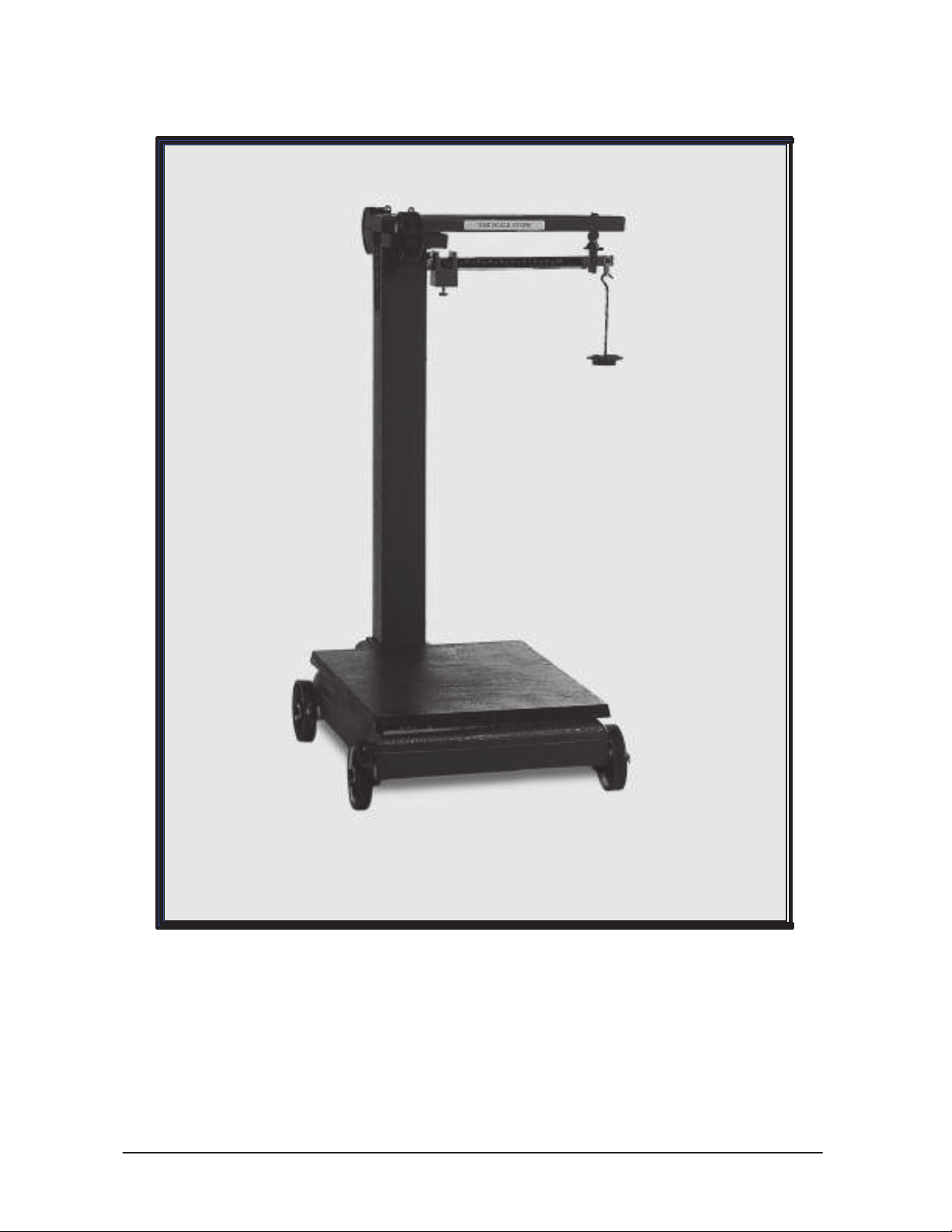
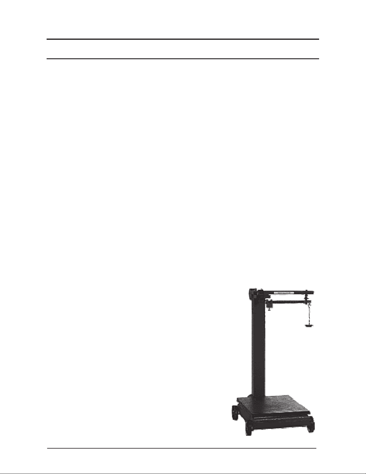
Portable Platform
Models BPP1000 & BPP2000
©
Copyright 1990-2013 Fancor Inc.
Scale
50699 Revision 4 ‒ 03-13

Portable Platform
Models BPP1000 &
03/13 50699 Rev 4
Scale
BPP2000

©
Copyright 1990-2013
This document contains proprietary information protected by copyright. All rights are reserved; no part
of this manual may be reproduced, copied, translated or transmitted in any form or by any means
without prior written permission of the manufacturer.
Disclaimer
Every effort has been made to provide complete and accurate information in this manual.
However, although this manual may include a specifically identified warranty notice for the product,
Fancor Inc. makes no representations or warranties with respect to the contents of this manual,
and reserves the right to make changes to this manual without notice when and as improvements
are made.
Fancor Inc. shall not be liable for any loss, damage, cost of repairs, incidental or consequential
damages of any kind, whether or not based on express or implied warranty, contract, negligence,
or strict liability arising in connection with the design, development, installation, or use of a scale.

Amendment Record
Portable Platform Scale
Models BPP1000 & BPP2000
Document 50699
Manufactured by Fancor Inc.
821 Locust St.
Kansas City, MO 64106
Created 08/1990
Rev. 1 8/1990 Released Manual
Rev. 2 11/2006
Rev. 3 04/2012 Corrected parts list description
Rev 4 03/2013 Misc. revisions
Updates made to include BPP2000;
Revisions in text formatting, illustration updates,
Descriptions, and processes
03/13 5 50699 Rev. 4

T
able of Contents
SECTION 1: INTRODUCTION ........................................ 9
Scope of This Manual ................................................ 9
Modifications ....................................................... 9
Customer/Operator Responsibilities .................................... 9
Repair Restrictions .................................................. 9
Service Responsibility ................................................ 9
Operating Requirements .............................................. 9
Description ........................................................ 10
Specifications ...................................................... 10
SECTION 2: INSTALLATION ......................................... 11
Unpacking ......................................................... 11
Tools Required for Assembly ......................................... 11
Base Assembly .................................................... 12
Pillar and Beam Assembly ........................................... 14
Zeroing the Beam .................................................. 16
Troubleshooting .................................................... 17
SECTION 3: PARTS ................................................ 18
Parts List .......................................................... 18
Parts Diagram ..................................................... 20
03/13 7 50699 Rev. 4

03/13 8 50699 Rev. 4

Section 1: Introduction
Scope of This Manual
This manual provides instructions for the Portable P
BPP1000
•
Please read this manual carefully before assembling.
•
Untrained personnel should not attempt to make any adjustments not specified in
and
B
PP2000
latfor
.
m
Scale Models
these instructions.
Modifications
Absolutely NO PHYSICAL ALTERATIONS (mounting holes, etc.) are to be made to
this equipment.
Customer/Operator Responsibilities
It is the customer/operator’s responsibility to maintain and protect the scale from
accidental or malicious damage.
Repair Restrictions
The Portable Platform Scale must be repaired following specific current
warranty policies for this product.
Service Responsibility
The Portable Platform Scale is factory calibrated, and supplied to the
customer ready to be unpacked, assembled and placed into operation.
Operating Requirements
•
The scale must be operated on a firm, level surface.
•
A bubble level is provided for checking the level condition of the scale.
03/13 9 50699 Rev. 4

y
(
g)
g)
Section 1:
Description
The Portable Platform Scale is a compact portable unit designed for light to
medium operation. It requires no external power connections and will operate in a
wide variety of environmental conditions.
Specifications
Introduction
Specificati
Capacit
Division Size
on
s
1000 lbs.
BPP 1000
1/2lb
454.5 k
BP 2000
2000 lbs. (909 k
.
1 lb
.
Platform Cast iron base Cast iron base
Platform Size 21" x 23½" 24" x 31"
Overall Height 42¾" 42¾"
Platform Height About 7" About 7"
Cast Iron Lever
Cast Iron
Weighing System
t
em
Sys
03/13 10 50699 Rev. 4
Lever Sys
t
em

Section 2: Installation
Unpacking
•
Check the packing materials for loose parts or hardware before disposal.
•
Check that all parts are included using the packing list.
•
Check for component damage that may have occurred during shipping
•
The scale platform under-structure arrives fully assembled, with the levers in their
proper positions.
Tools Required for Assembly
•
Needle nose pliers
•
Flat head and Phillips head screwdrivers
•
An adjustable wrench
03/13 11 50699 Rev. 4

Section 2:
Installation
Base Assembly
NOTE: The following descriptions refer to “Key#” (#4, etc.) to describe parts. Use the
parts list and Key# in the list to identify all such parts.
1. Place the Platform Sub
blocks to raise it up off the floor, if possible.
Assembly
on the floor
upside-down,
preferably on 2x4
2. Remove the cotter pins and washers from one side of the Axle Rod (#19).
•
Axle assembly includes an affixed cotter pin (#17), a 5”
3. Insert the Axle Rod
a flat washer (#18).
Assembly
through the two axle rod holes, side-to-side.
4. Place one flat washer (#18), then a wheel (#16) over the other end.
03/13 12 50699 Rev. 4
wheel (#16), and then

Section 2:
Installation
Base Assembly, Continued
5. Insert a cotter pin (#17) through the
Axle Rod.
•
Using needle nose pliers, bend
back both haves of the cotter pin
to secure the wheel assembly.
6. Repeat steps two through four (2-4)
for the second axle.
7. Center the axles in the base, and then
insert the four
locking
screws (#15)
into each of the tapped holes in the
bottom of the base.
•
Located directly under the axle
holes
8. Tighten the locking screws, and then
secure the Lock Nuts (#14).
9. Turn the platform over so it sets on
the wheels.
After inserting the four Cotter Pins, center
axles, tighten the Locking Screws, and
secure the Lock
Nuts.
the
then
03/13 13 50699 Rev. 4

Section 2:
Installation
Pillar and Beam
Assembly
1. Thread the two (2) Pillar Support Rods (#1) into the tapped holes provided in the base.
•
The end with the longer thread should fit into the platform (about 1⁄2 inch).
2. Place the Pillar (#2) down over the support
rods with the pillar cut-outs facing the right and
left of the platform.
3. Insert the Steelyard Rod (#35) down through
the pillar.
•
The bent hook on top; the loose Swivel
4. Hook the Steelyard Rod (#35) to the
03/13 14 50699 Rev. 4
Hook on the bottom.
•
The hook opening should be toward the
platform when properly placed.
•
DO NOT remove the washers from the
Steelyard Rod.
Long
Lever Tip Pivot (
•
Temporarily, hook the upper end of
#34).
Steelyard Rod on the pillar
cut-out.
the
Hook the Steelyard Rod to
Long Lever Tip
Pivot.
the

y
Section 2:
Installation
Pillar and Beam Assembly, Continued
5. Place the cast iron Beam Support (#39) over the Steelyard Rod with the hook
facing to the right (when facing the scale platform).
6. Insert the Beam Cap (#45) onto the pillar rods.
•
The long side will be to the right.
7. Place Washers over the pillar rods, and then screw on the
two (2) Acorn Nuts (#44).
•
Hand-tighten only, at this time.
8. On the butt end on Beam
Load Loop to the Steelyard
•
See image to the right.
Assembly,
Rod.
hook the bottom
9. Pulling the Beam up, hook the top Fulcrum Loop (of the
Beam
•
10.
Insert the Beam Lock (#43) onto the front end of the
Beam Assembly.
•
11.
Slide t he Beam Lock (#43) over the
Beam and align it with the two (2) holes
in the Beam Cap (#45).
12.
Fasten the Beam Lock to the Beam Cap
with the two (2) Hex Bolts (#46).
•
13.
Hang the
(
14.
Set the Sliding Poise (#52) to zero and
hand tighten the screw on its under-side.
•
•
Assembly)
to the hook on the Beam Support
(#39).
The beam should hang loosely from the two hooks.
See image to the right.
The handle faces the scale platform.
Counterpoise Assembly
#54) from the Beam Tip
Check that the beam is straight and does
not touch the sides of the Beam Lock.
Shift the Cap if necessary to straighten,
and then tighten the acorn nuts securely
Loop.
Insert the Beam Lock onto the end of the
Assembly, then align the Beam Lock under the
with an adjustable wrench.
Hook the bottom Load
to the Steelyard Rod.
the Beam up, hook the
Fulcrum
two
holes in the Beam Cap. Fasten this
assembl
with
the two Hex
Loop.
Bolts.
Loop
Pulling
top
Beam
03/13 15 50699 Rev. 4

Section 2:
Installation
Zeroing the Beam
Note:
1. Unlock the Beam Lock Loop to allow the beam to balance.
2. Balance the beam by adjusting the balance ball at the butt end of the beam, using a
The scale is now assembled.
03/13 16 50699 Rev. 4
Check that the weighing platform "floats" on the levers' pivots and bearings and
does not bind or set to one side. The platform should return to a centered position if
moved to any position then released.
•
The beam should move up and down freely coming to rest in the center of the trig
lock opening.
screwdriver.
•
Turning the screw CW (Clock-Wise) raises the beam
•
Turning the screw CCW (Counter Clock-Wise) lowers the beam.

Section 2:
Installation
Troubleshooting
If the beam will not balance using the balance ball, check the
•
Is the poise is at 0 (zero), and is the poise screw is snug?
•
Is the platform free and “floating”?
•
Is the beam load rod connected properly on both ends?
•
Is something under the platform inhibiting the levers (floor debris)?
•
Are there any weights on the counterpoise hanger, and is it on the Tip
•
Is the beam hanging from the middle loop?
•
Is the Beam Lock Loop (#43) open?
following:
Loop?
Apply a slight pressure to the scale platform and see if the beam tip rises.
•
If it does, continue onto balancing step.
•
If it does not, recheck mechanical assembly.
If the scale beam
still does not balance (beam rises with slight pressure),
perform the following:
1. Use a screwdriver to 'center' the balance ball at the butt end of the beam.
2. If the beam is up, apply small amounts of weight (BBs) to the top of the
C
ounterpoise.
3. If the beam is low, remove the
Counterpoise
hanger (#54), loosen the hanger rod
by turning and holding the bottom nut, and remove a small amount of lead shot.
4. Add or remove small amounts of weight until beam balances.
5. Secure the counterpoise hanger with added or removed weight.
03/13 17 50699 Rev. 4

Section 3: Parts
Parts List
Key #
Part #
B
PP1000
55017
B
PP2000
Part
#
Description
BPP1000
Series, 24" x 21",
1K x .5, NTEP,
Portable Beam
55789*
1 71622 78796* Set of Pillar
2 58933 77228*
3 95847 Cover Assembly,
4 95848
5 95855 Cotter
6 58937 Bearing,
7 95856 Screw, Phillips
8 95857 Screw,
9 95858 Level,
10 95859 Pin, Corner
11 71623 Loop,
12 71624 Bearing, Corner
13 71625 Cotter
11, 12, 13 58938 Corner Loop
14 95867 Nut,
15 95868 Bolt, Hex
16 95869 Wheel, 5"
17 71628 Cotter
18 71629 Washer,
19 71630
24 95861
25 72948 Lever Assembly,
26 58939 Center Connection Assembly (26, 27, 28, 29,
27 Clip, Center
28 Link, Center
29 Cotter
30 95862
31 95863
32 75712* Upper Bearing, Center
33 72947 75713* Long Lever
34 95864 Long Lever Tip
35 58934 Steelyard Rod
BPP2000
Pillar
Frame
Axle
Pivot
Pivot
Pivot
Series, 24" x 31",
Rods
Pin
Platform
Head
Allen
Bubble
Loop
Corner
Pin
Assembly
Hex
Head
Diameter
Pin
Flat
Connection
Connection
Pin
Assembly
Pivot
Assembly
Platform
Loop
Short
2K x 1, NTEP,
Connection
Portable Beam
32)
xxxxx* Indicates a part number for the BPP2000.
03/13 18 50699 Rev. 4

p
A
y
A
t
Section 3:
Parts
Parts List, Continued
B
Key #
36, 37, 38 71594 Loo
37
38
39
95839 77229* Support Beam
40
71591
40, 41, 42 71595
41
42
43
95840
44
71592
45
95841 77227* Cap, Beam
46
71593
47
48
47, 48, 49 95843
PP1000
Part #
55017
50
71632
51
51, 52, 53 95842
53
54, 58,
60
55, 56, 57
55, 56, 57
55
56
57
58
59
60
61
62
N/S
N/S
59,
58935
58936
95853
95854
95865
95866
71586
71587
B
PP2000
Part #
71633* BPP2000 2000 lb. Portable Beam
75711* BPP2000 BPP2000 Beam Inser
Description
ssembl
Cotter Pin
Bearing
Loop
LoopAssembly
Cotter Pin
Bearing
LockAssembly, Beam
corn Nut (2)
Hex Bolt (2)
Screw, Balance WeightAdjustment
Weight, Balance
BeamAssembly (100 x 0.5 lb)
BPP1000 1K x 0.5 NON-NTEP Beam
Pivot
Pivot
PoiseAssembly
Loop
Counterpoise Stem Assembly
71598* Set of SE Weights
74392* Set of Metric Weights
1 lb. Counterpoise Weights
2 lb. Counterpoise Weights
4 lb. Counterpoise Weights
Top, Counterpoise
Cup, Counterpoise
Nut, Hex
Pin
Cotter Pin
Set of Corner Loops
Set of Bearing Corner Loops
xxxxx*
03/13 19 50699 Rev. 4
Indicates a part number for the BPP2000.

Section 3:
Parts
Parts Diagram
45
44
39
40
49
1
35
8
7
9
34
2
46
43
52
55
56
25
14
54
31
26
15
24
57
3
61
62
33
6
5
10
12
13
11
17
18
16
19
03/13 20 50699 Rev. 4
4


Portable Platform Scale
Models BPP1000 & BPP2000
Document 50699
 Loading...