

Operator Manual
Fairbanks Access Solutions
Model: AN Series
powered by Titan Technology
2012-2013 by Fairbanks Scales, Inc.
All rights reserved
Rev. 1
51299
01/13


Amendment Record
Fairbanks Access Solutions
Model: AN-Series
Document 51299
Manufactured by Fairbanks Scales Inc.
821 Locust
Kansas City, Missouri 64106
Created 10/2012
Revision 1 01/2013
powered by Titan Technology
01/13 3 51299 Rev. 1

Disclaimer
Every effort has been made to provide complete and accurate information in this manual. However, although this
manual may include a specifically identified warranty notice for the product, Fairbanks Scales makes no
representations or warranties with respect to the contents of this manual, and reserves the right to make changes
to this manual without notice when and as improvements are made.
It is the responsibility of the requesting party to develop, maintain, install, and connect networking devices and
general network connectivity as it applies to the originating party’s network. No warranty or guarantee, expressed
or implied, concerning the network, its design, its installation, or operational characteristics has been offered by
Fairbanks Scales. Fairbanks Scales shall not be liable for any loss, damage, cost of repairs, incidental or
consequential damages of any kind, whether or not based on express or implied warranty, contract, negligence,
or strict liability arising in connection with the design, development, installation, or use of an intended network
.
Trademarks
All other product names mentioned herein are used for identification purpose only and may be
trademarks and/or registered trademarks of their respective companies.
© Copyright 2012-2013
This document contains proprietary information protected by copyright. All rights are reserved; no part of this
manual may be reproduced, copied, translated, or transmitted in any form or by any means without prior written
permission of the manufacturer.
01/13 4 51299 Rev. 1

Table of Contents
Section 1: General Information ................................................................................................................... 7
1.1. Brief Overview ................................................................................................................................ 7
1.2. System Configurations .................................................................................................................... 8
1.3. Features ......................................................................................................................................... 9
1.4. Safety Guidelines .......................................................................................................................... 10
1.5. Recommendations ........................................................................................................................ 11
Section 2: Maintenance ............................................................................................................................ 12
2.1 Securing the Terminal cabinet ........................................................................................................ 12
2.2. Opening Secure Access Entry Unit .................................................................................................. 13
2.3. Loading the Printer Paper .............................................................................................................. 14
2.4. Create Backup From USB Memory Stick ......................................................................................... 17
2.5. Restore From Backup Using USB Memory Stick .............................................................................. 19
2.6. Power Down Terminal ................................................................................................................... 20
2.7. Parts Orientation .......................................................................................................................... 22
2.8. Contact Support ............................................................................................................................ 23
Section 3: Access Terminal Screens Defined .............................................................................................. 25
3.1 Home ............................................................................................................................................ 25
3.1.1. System Status Page ........................................................................................................................... 25
3.1.2. Reports Page ..................................................................................................................................... 27
3.1.3. System Setup Menu ........................................................................................................................... 28
3.1.4. Device Setup ...................................................................................................................................... 29
3.1.5. Diagnostics ........................................................................................................................................ 29
3.1.6. About ................................................................................................................................................. 30
3.2 System Setup ................................................................................................................................. 31
3.2.1. Access Unit Setup .............................................................................................................................. 31
3.2.2. Credit Card Processor Settings ........................................................................................................... 33
3.2.3. Date And Time Setup ......................................................................................................................... 34
3.2.4. Email Setup ........................................................................................................................................ 35
3.2.5. Email Subscriptions ............................................................................................................................ 36
3.2.6. Hours Of Operation Setup ................................................................................................................. 37
3.2.7. Matrex Setup ..................................................................................................................................... 38
3.2.8. Payment Setup .................................................................................................................................. 41
3.2.9. Scale Ticket Setup .............................................................................................................................. 42
3.2.10. Timeout And Delay Setup ................................................................................................................ 45
3.2.11. Traffic Control Setup ........................................................................................................................ 49
3.2.12. Transaction Flow Setup ................................................................................................................... 58
3.2.13. Units Of Measure ............................................................................................................................. 60
3.2.14 User Setup ........................................................................................................................................ 61
3.2.15. Weightment Setup ........................................................................................................................... 64
3.2.16. Welcome Screen .............................................................................................................................. 69
3.3. Device Setup Menu ....................................................................................................................... 73
3.3.1. Internal Devices ................................................................................................................................. 74
3.3.2. Input/Output Setup ........................................................................................................................... 76
3.3.2 Configurations for PDQ IO node ......................................................................................................... 84
3.3.3. Network Setup ................................................................................................................................... 88
3.3.4. Remote Display Setup ........................................................................................................................ 90
3.3.5. Rfid Reader Setup .............................................................................................................................. 92
3.3.6. Scale Indicator Setup ......................................................................................................................... 98
01/13 5 51299 Rev. 1

Table of Contents
3.3.7. Sign Setup ........................................................................................................................................ 102
3.4. Diagnostics Menu ....................................................................................................................... 104
3.4.1. Audio Diagnostics ............................................................................................................................ 105
3.4.2. Credit Card Logs............................................................................................................................... 106
3.4.3. I/O Diagnostics ................................................................................................................................ 107
3.4.4. Keypad Control ................................................................................................................................ 109
3.4.5. Network Diagnostics........................................................................................................................ 110
3.4.6. Diagnostics Options ......................................................................................................................... 111
3.4.7. Restart Page .................................................................................................................................... 112
3.4.8. Screen File Viewer ............................................................................................................................ 113
3.4.9. System Logs ..................................................................................................................................... 114
3.4.10. System Management .................................................................................................................... 115
3.4.11. Transaction Cache ......................................................................................................................... 115
3.4.12. About Page .................................................................................................................................... 116
01/13 6 51299 Rev. 1

Section 1: General Information
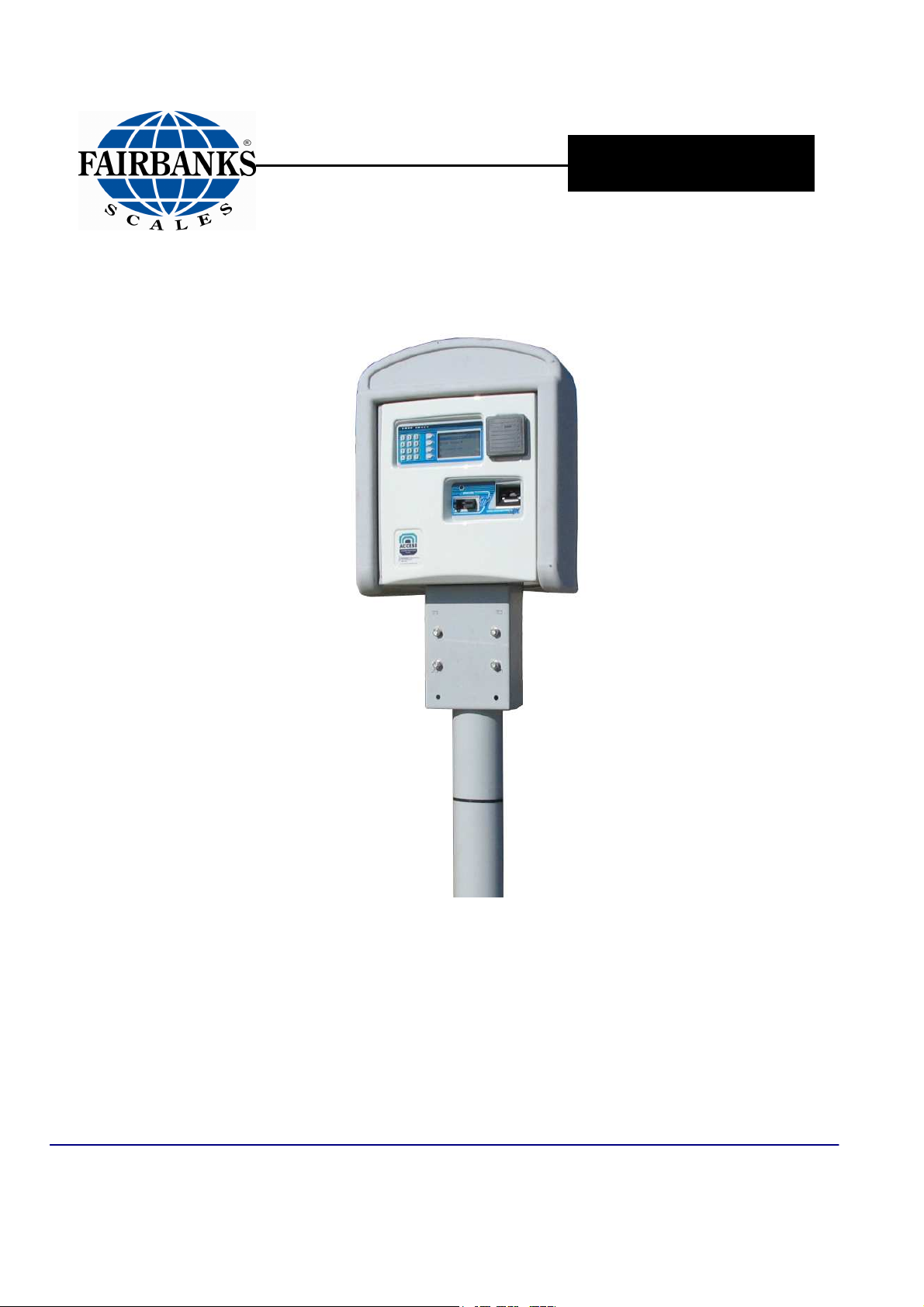
1.1. Brief Overview
Fairbanks Access Solutions system controls entrance/exit of vehicles hauling
materials in/out of a facility. The Access Solutions system contains 1 or more Access
Terminals and a data processing system (i.e. MatreX).
VEHICLE WEIGHING PROCESS ORDER
1. Vehicle drives onto a scale (provided by customer).
2. Vehicle is identified through 1 of 3 options: short/long range RFID reader,
card, or a manual process where the customer enters a code on Access
Terminal.
3. MatreX looks up vehicle information and sends it to the Access Terminal.
4. Vehicle is processed based on specific vehicle weighing process information.
5. Terminal receives vehicle weight from scale indicator (provided by customer).
6. Weight data and customer responses are sent to MatreX.
7. If transaction is complete, customer receives a detailed scale ticket receipt.
SAMPLE TRANSACTION PROCESS SCENARIOS
Fairbanks Access Solutions processes vehicles in multiple ways through weight:
Processing by Weight
• Weigh In and Weigh Out: Truck weighs entering the facility and weighs exiting
the facility, 2 weighments
• Weigh In w/ Stored Tare Weight: Truck weighs entering the facility then exits
facility, 1 weighment
• Weight Out w/ Stored Tare Weight: Truck enters facility then weighs exiting
facility, 1 weighment
• Multiple Weighs: Mixed load vehicles are weighed multiple times while at the
facility
GROSS WEIGHT (full weight) = VEHICLE WEIGHT + MATERIAL
TARE WEIGHT (empty weight) = VEHICLE WEIGHT
NET WEIGHT (material weight) = GROSS WEIGHT (vehicle + material) - TARE
Gross, Tare, & Net Weight Relationships
01/13 7 51299 Rev. 1
Section 1: General Information
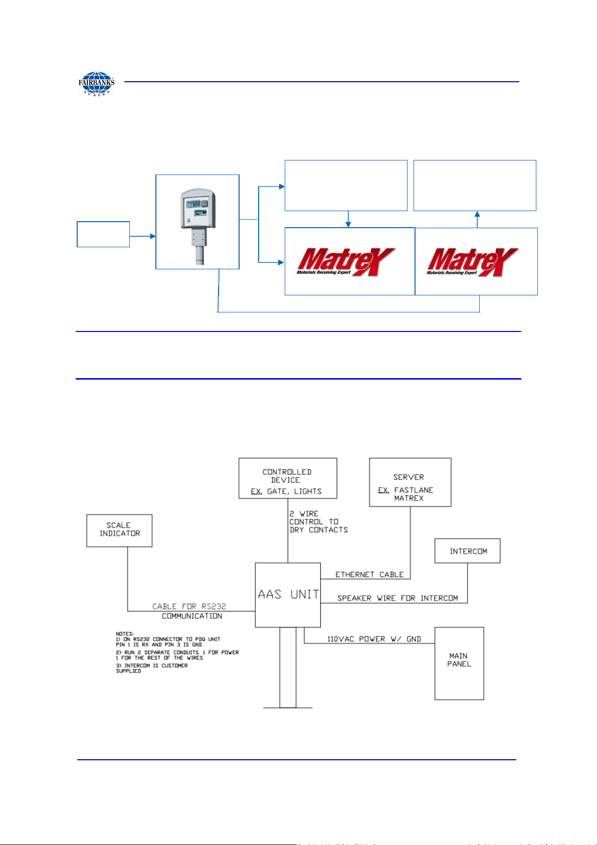
1.2. System Configurations
Fairbanks Access Solutions is configurable in multiple ways:
Data Processing System
3rd Party
Data Processing System
3rd Party
Scale
Note:
If using a 3rd party data processing system custom software integration, additional software
installation will be required.
01/13 8 51299 Rev. 1

Section 1: General Information
1.3. Features
• Various Mounting Options and Contemporary Design
• Easy Maintenance
• Replaceable Keypad
• Short-Range/Long Range RFID Reader
• Custom Inputs (start transaction, detect vehicle)/Outputs (lights, gates)
• Magnetic Card Reader
- Provides users with card success or failure status through audio sounds and
assistance
- Jam proof operation, provides clear and safe path for entering debris and/or
water
• Electrical System
- Modular design allows for multiple component replacements.
- Protects against damage and operational problems during low power
and/or lightning storms.
- Battery Backup System providing 12VDC battery power during power loss.
(2 weeks if fully charged)
- Climate Control System
- Provides continuous air and heat circulation to internal Access Terminal
devices
01/13 9 51299 Rev. 1

Section 1: General Information
1.4. Safety Guidelines
• Any personnel operating or performing maintenance on the equipment must read
and adhere to all safety and machine operating instructions
• When installing or operating a piece of Fairbanks Access Solutions equipment,
adhere to all fire and safety rules/regulations, per local, state, and national
authorities; consult local code authorities for additional information
• The equipment must be maintained and operated only by competent personnel.
The user must operate appropriate tools and understand electrical wiring and
potential hazards. If there is any doubt, contact the Fairbanks Access Solutions
service representative to arrange professional maintenance of the equipment.
• Do not climb or stand on equipment for any reason
• Use appropriate protective gear and tools during installation
• Personnel are to perform lockout/ tag safety requirements, per OSHA regulations
• All personnel should read, be familiar with, and observe all CAUTION, DANGER,
AND WARNING decals/labels placed on equipment
• Follow all maintenance schedules and procedures; it is critical to maintain trouble
free performance of FBAS equipment
• There may be residual voltage in the unit-proceed with caution
• The battery is a high output style that stores a great amount of energy; enlist care
when servicing the battery, power board, or controller
The unit contains a Rechargeable Sealed Lead-Acid Battery. The battery should
NOT be disposed of in normal trash containers, but recycled. In the USA call 1800-SAV-LEAD. The battery is functionally similar to a car battery supplier.
• Read battery markings for additional safety and disposal information
• Ensure all shields, guards, nuts, bolts, and screws are in place and secure.
01/13 10 51299 Rev. 1

Section 1: General Information
DO
Follow all maintenance schedules for trouble
-
free performance of
Fairbanks
Access S
olutions
DO NOT
1.5. Recommendations
Read all manuals completely.
Follow all instructions completely.
equipment.
Ensure backup battery remains connected during controller unit service to prevent incorrect date, time,
or possible data loss when power is restored.
Verify high voltage is disconnected by checking the voltage with a volt meter on each circuit.
Ensure the following devices are fully operational: card reader, receipt printer, Ethernet gateway, and
internet account with email.
Monitor emails and transactions, possible errors will be indicated in Email error message; frequently
check.
Properly recycle batteries.
Change codes regularly and remove past users from list to maintain security.
Use care when setting operational procedures and user security levels.
Turn off main circuit breaker and wait 60 seconds prior to disconnecting battery or main power
controller box.
Enlist care when handling battery; it stores abundant energy and remains active after main power is
turned off.
Test all common transactions prior to processing customer transactions AND opening business.
Save the initial setup account configuration for future reference.
For transactions, completely insert card into reader and quickly withdraw.
DO NOT operate the system until all safety features are tested.
DO NOT attempt to add or retrofit components to equipment without first contacting FBAS.
01/13 11 51299 Rev. 1

Section 2: Maintenance
2.1. Securing the Terminal cabinet
The Access terminal comes with a padlock when inserted, locks and prevents
opening the housing. For record keeping have the key tag # written down and stored.
If one or both keys are
lost the key tag# can be
used to reorder keys for the exact lock. Contact a local Fairbanks distributor or tech
services at toll free 800-451-4581, press 2, press 1.
01/13 12 51299 Rev. 1
Section 2: Maintenance
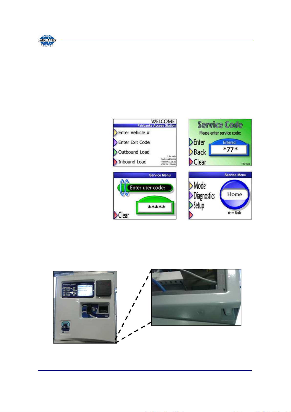
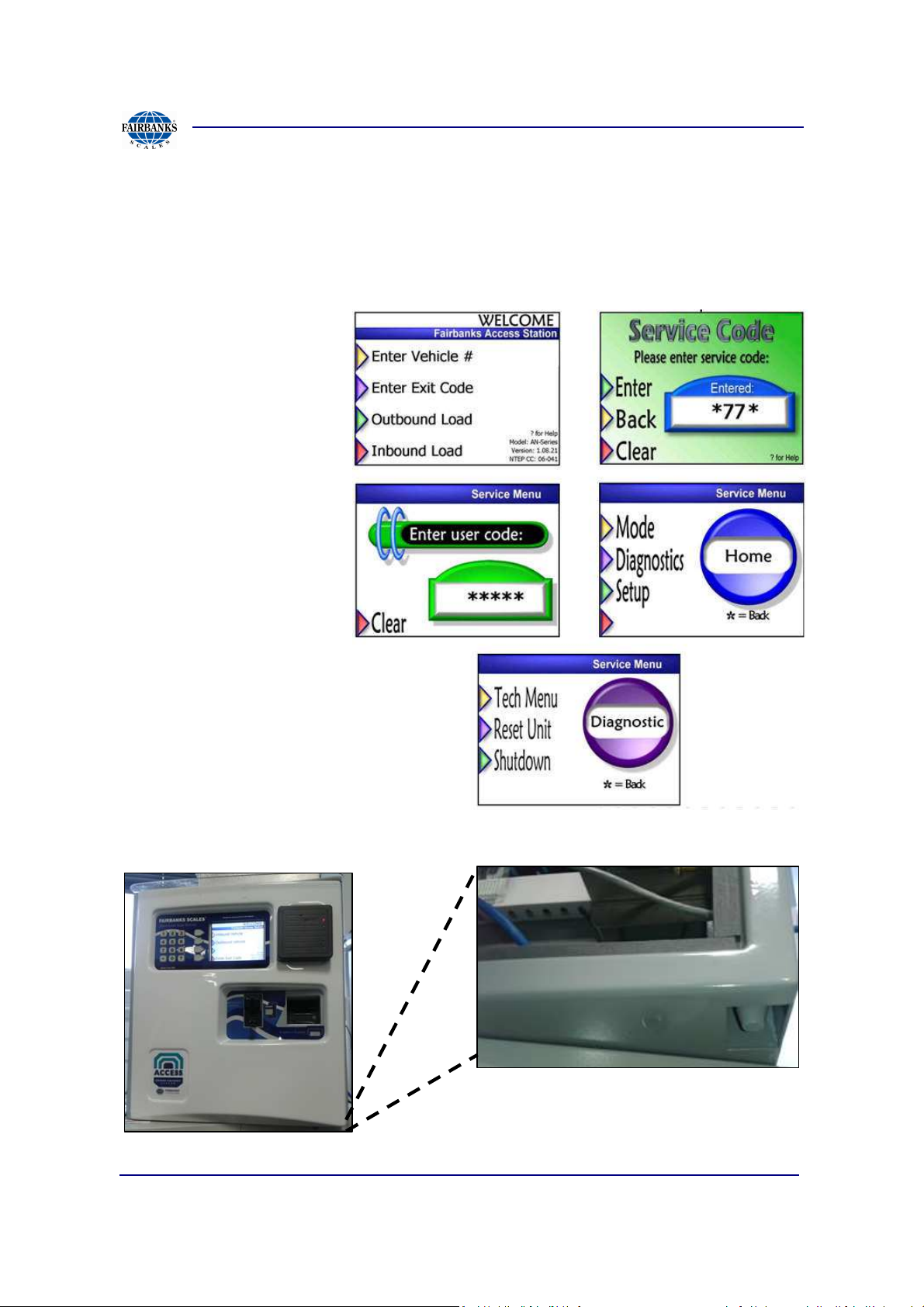
2.2. Opening Secure Access Entry Unit
By default the Access Terminal is configured to sound an alarm from
unauthorized users when a service and user code is not entered. To change
paper or further maintenance enter the below steps.
STEPS IN DISABLING ALARM
From keypad, type:
*77*
12345
From the Service Menu
Home screen the door
alarm will be disabled.
Open cabinet door by pressing up on release lever, located in bottom right of unit.
.
01/13 13 51299 Rev. 1

Section 2: Maintenance
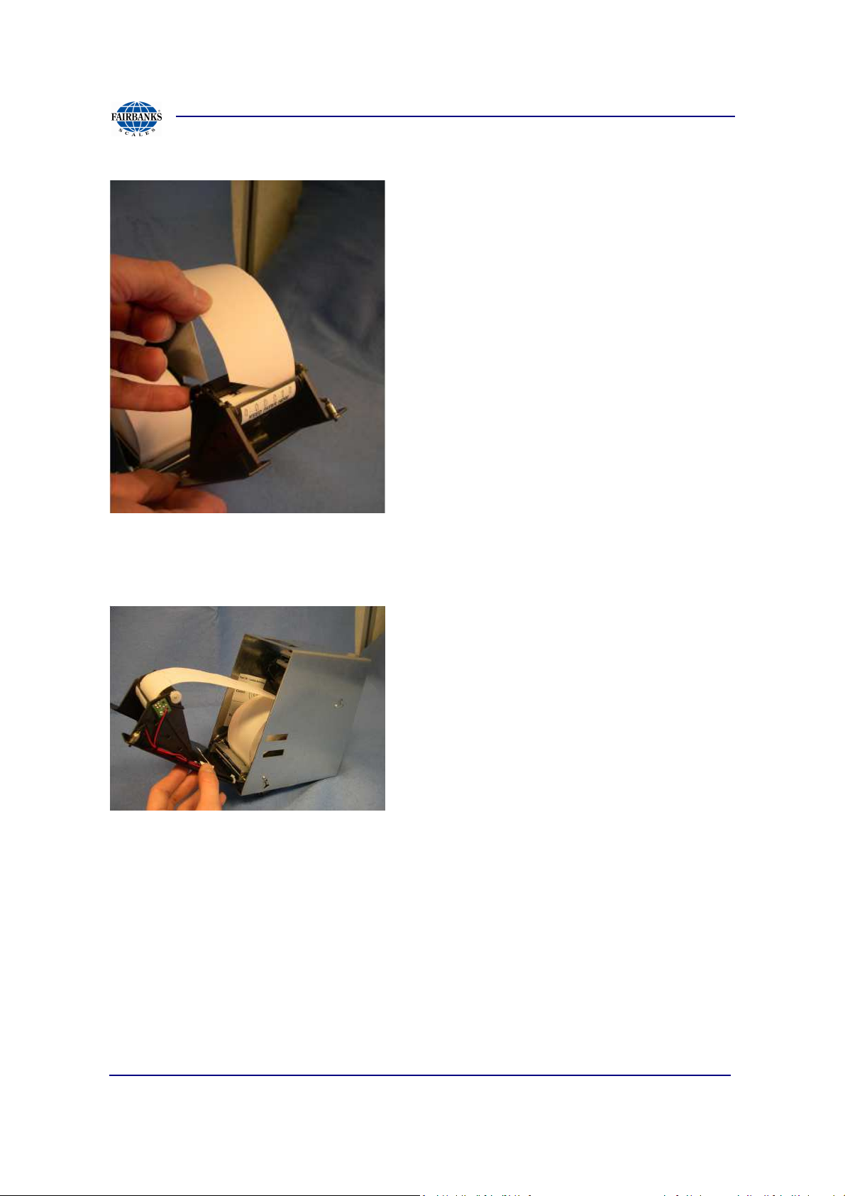
2.3. Loading the Printer Paper
1. Open the front door assembly, picture shown without printer paper loaded.
2. Place paper roll inside of printer assembly, picture shown with metal core
inside of roll.
3. Verify receipt paper is pulling from top down, note position is pulled close to
feed roller.
01/13 14 51299 Rev. 1
Section 2: Maintenance
2.3. Loading the Printer Paper, Continued
4. Feed paper through slot in front of white plastic hinge, note ,” white feed here”
sticker position.
5. Side view of printer assembly loaded without front door hinge open, note
paper is in the feed area.
01/13 15 51299 Rev. 1

Section 2: Maintenance
2.3. Loading the Printer Paper, Continued
6. After successfully loading paper and closing the printer door, a configuration
page will print.
If paper fails to print, press the button on the top right quadrant of the printer
door, this should manually feed paper through.
If no paper is printing or feeding through the printer, verify the previous 5 steps
again; possible causes could be pinched paper in printer assembly door or the
paper has been fed improperly.
01/13 16 51299 Rev. 1
Section 2: Maintenance
2.4. Create Backup From USB Memory Stick
After successful installation and configuration of the site it is good practice to back up
the Access Terminal to lessen future down time.
Note(s):
Using the navigation prompts will create a directory with the units’ serial number then
the data is stored inside it. This procedure allows multiple units to be backed up to a
single USB jump drive. Restoration of files reflects on the serial number assigned to
the unit.
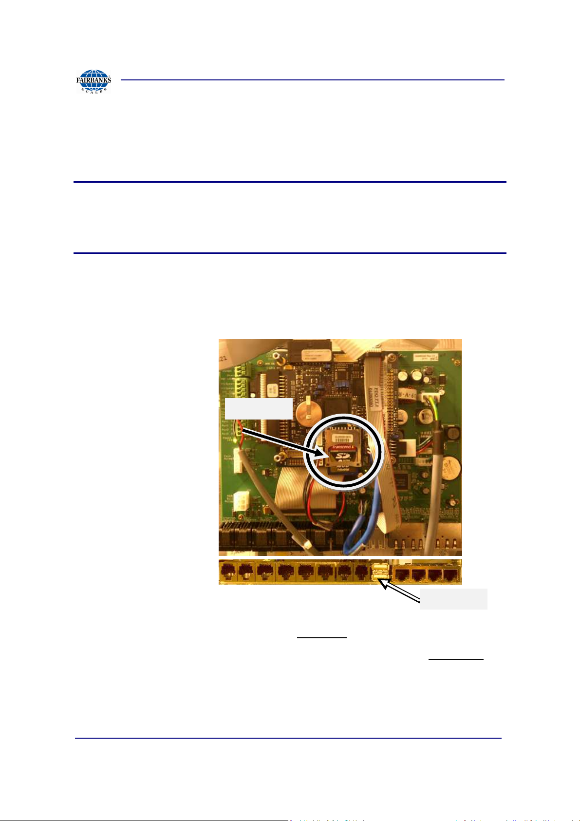
To backup, place a USB drive in the USB connector on the communication board,
located in region (a) then follow the screen prompts to backup files.
If the Titan board requires replacement, remove the existing SD card (region b) and
insert into the replaced
board. If the SD card is
undamaged the version
and configuration
information will transfer
over to the new board. If
the SD card is damaged a
preloaded Titan card can
be installed and updated
using the USB drive.
region (b)
.
Follow the navigation steps below from the “Welcome”, location.
From a successful power up the first screen or state is the main state, “Welcome”.
Welcome >> Press *77* >> Press 12345 >> Press 2nd Key down >> Press 1st Key
>> Press 7 >> Press 1 for backup all data
01/13 17 51299 Rev. 1
region (a)
Section 2: Maintenance
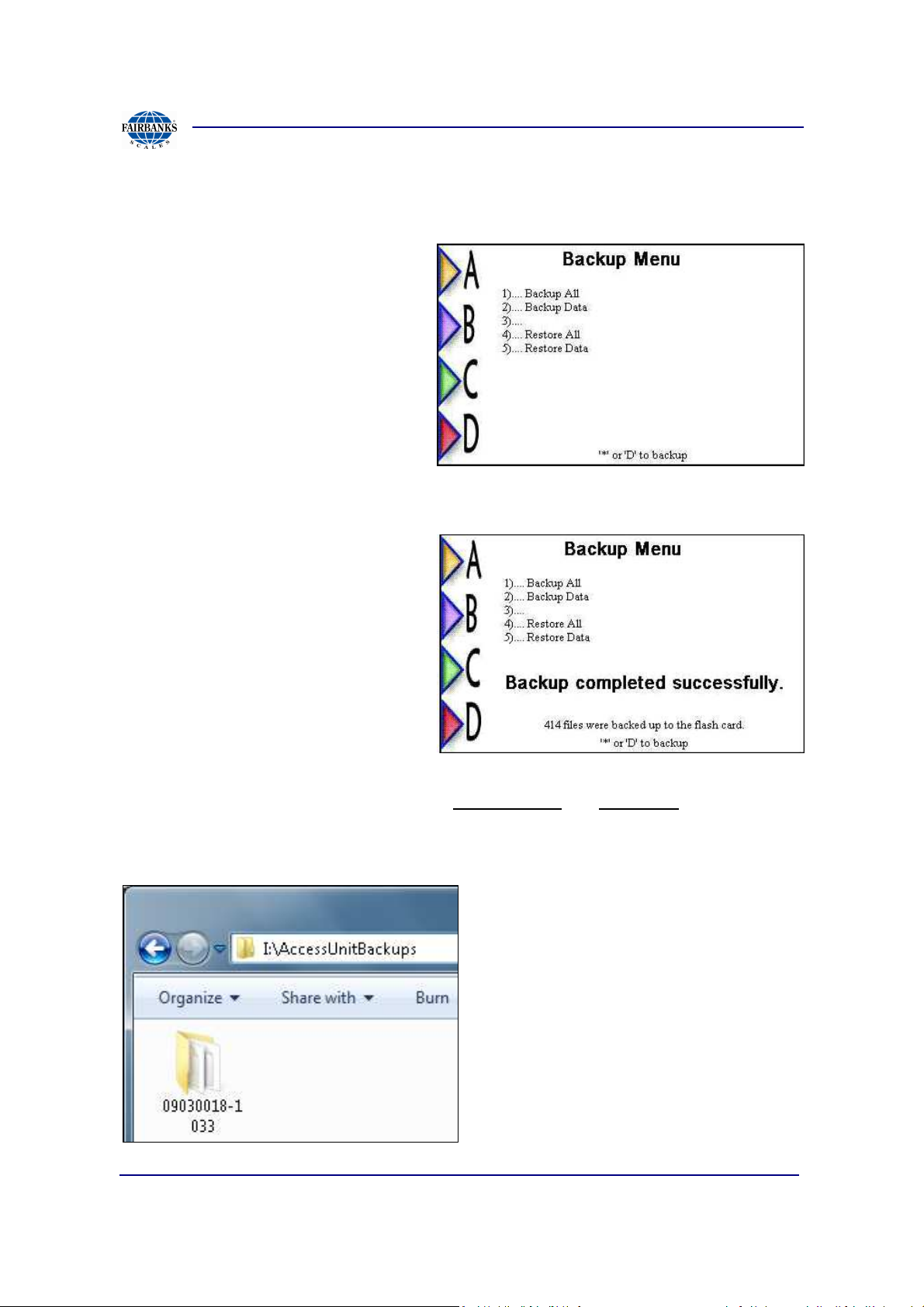
2.4. Create Backup From USB Memory Stick, Continued
To create a full backup chose option
1.
Screen update after backup
completed successfully.
When viewing the USB thumb drive on a Windows operating system, the drive should
mount as an additional drive letter under, My Computer OR Computer location.
Each Access Terminal backup creates a folder with the terminals serial number. This
allows storing multiple units due to the unique folder naming/serial number reference.
01/13 18 51299 Rev. 1

Section 2: Maintenance
2.5. Restore From Backup Using USB Memory Stick
Note(s):
The USB memory sticks restore is only necessary if the SD card or software has
been damaged. Otherwise all files pertaining to Access Terminal operations are
contained on the SD card.
If the SD card and software is intact but a hardware replacement of the Titan board is
necessary then only move the existing SD card to the new board.
With the USB memory stick inserted on the communications board, go to below
navigation points.
From a successful power up the first screen or state is the main state, “Welcome”.
Follow the navigation steps below from the “Welcome”, location.
First verify the serial number on the unit is correct, if not the restore will not have
correct reference to locate the previous backup.
1.) Login to the service home screen: Press *77* >> Press 12345 >>
2.) Select Setup: Press 3dnd arrow button
3.) Set Serial Number: Press 2nd arrow button
4.) View Serial Number, if correct press ‘*’ otherwise modify and save.
5.) Back out to the main Welcome Screen by continually pressing * till the
Welcome Screen is seen.
Restore after serial number confirmed.
1.) Login to the service home screen: Press *77* >> Press 12345 >>
2.) Select Diagnostics: Press 2nd arrow button
3.) Tech Menu: Press 1st arrow button
4.) Backup Menu: Press key 7
5.) Restore All: Press key 4
01/13 19 51299 Rev. 1
Section 2: Maintenance
2.6. Power Down Terminal
To properly power down the unit, follow the below instructions.
Steps In Complete Power
Down
From keypad, type:
*77*
12345
Choose option shutdown
unit from the Diagnostics
Service Menu.
Open cabinet door by pressing up on release lever, located in bottom right of unit.
.
01/13 20 51299 Rev. 1
Section 2: Maintenance
B
C
A
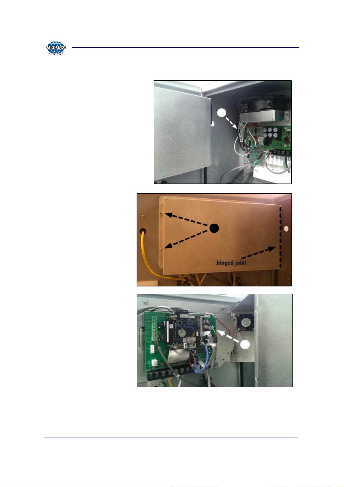
2.6. Power Down Terminal, continued
Locate breaker labeled A, and
power down by pressing the
switch downward.
Next locate and remove
standoffs labeled B from left
edge of door and open.
Locate and press in tab
connector labeled (C) to
remove power controller
cable. Gently pull away from
soldered connector.
*TIP
Powering off the unit in the
above manner then
reconnecting first C, waiting
15 seconds and turning
power back on to A;
produces a cold boot in which the unit fully reboots with all power discharged prior to
booting. A stuck screen with no feedback from the keypad indicates the same
symptom of a frozen mouse cursor on a typical pc system. With the system
responding from a reboot, further trouble shooting can take place.
01/13 21 51299 Rev. 1
Section 2: Maintenance
B
B
C
B
D
G
F
E
A
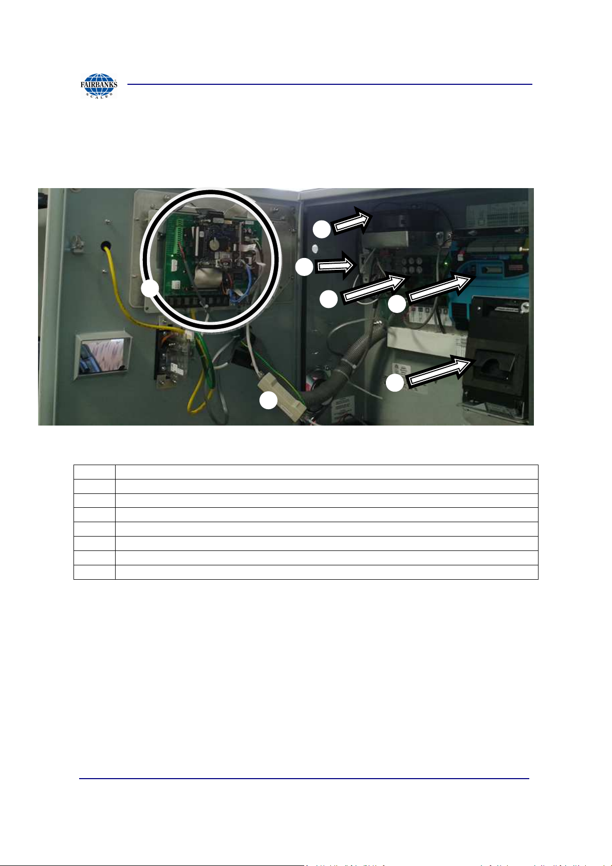
2.7. Parts Orientation
To help assist a Fairbanks technician in description the below items are listed in
order of possible connection.
Label Description
A Communication Board and Titan Board
B Heater and Blower Assembly
C Power Breaker
D AC Board
E IO Node
F Receipt Printer
G Network Filter
01/13 22 51299 Rev. 1
Section 2: Maintenance
B
B
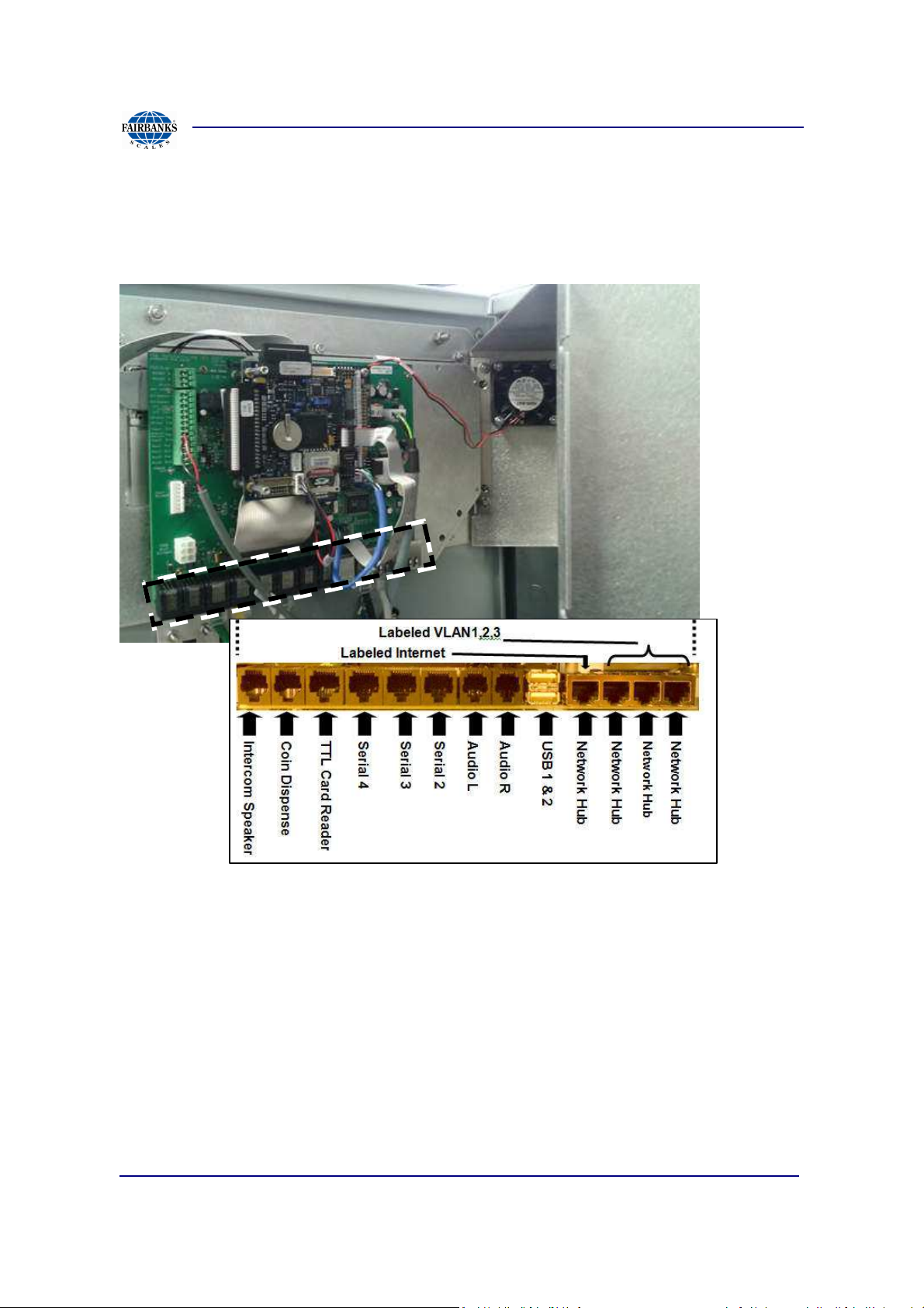
2.7. Parts Orientation, Continued
The below image shows the communications and Titan board along with the possible
connection ports from the bottom of the board.
01/13 23 51299 Rev. 1

Section 2: Maintenance
2.8. Contact Support
If service is needed beyond the scope of initial install or for questions
contact a service technician. The toll free line is (800) 451-4581, at the
prompt press 2 for the Automated Access Solutions then 1 for a
technician.
01/13 24 51299 Rev. 1
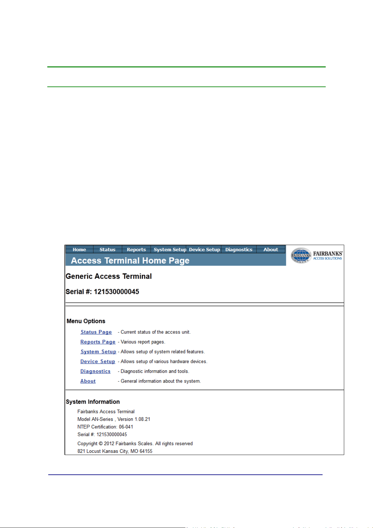
Section 3: Access Terminal Screens Defined
This section shows captures of the navigation screens contained in the Access
Terminal web configuration area, grouped by navigation top menu, containing submenu items. The home page screen shown here also contains the units name, and
serial number.
It is recommended to only view items in the Home and Status location unless a
Fairbanks authorized technician advises otherwise. Changing these setting
may report false data or shutdown automated scale usage.
3.1. Home
Containing submenu items: Status Page, Reports Page, System Setup,
Device Setup, NTEP Setup, Diagnostics
01/13 25 51299 Rev. 1
Section 3: Access Terminal Screens Defined
A
B
C
D
B
C
D
A
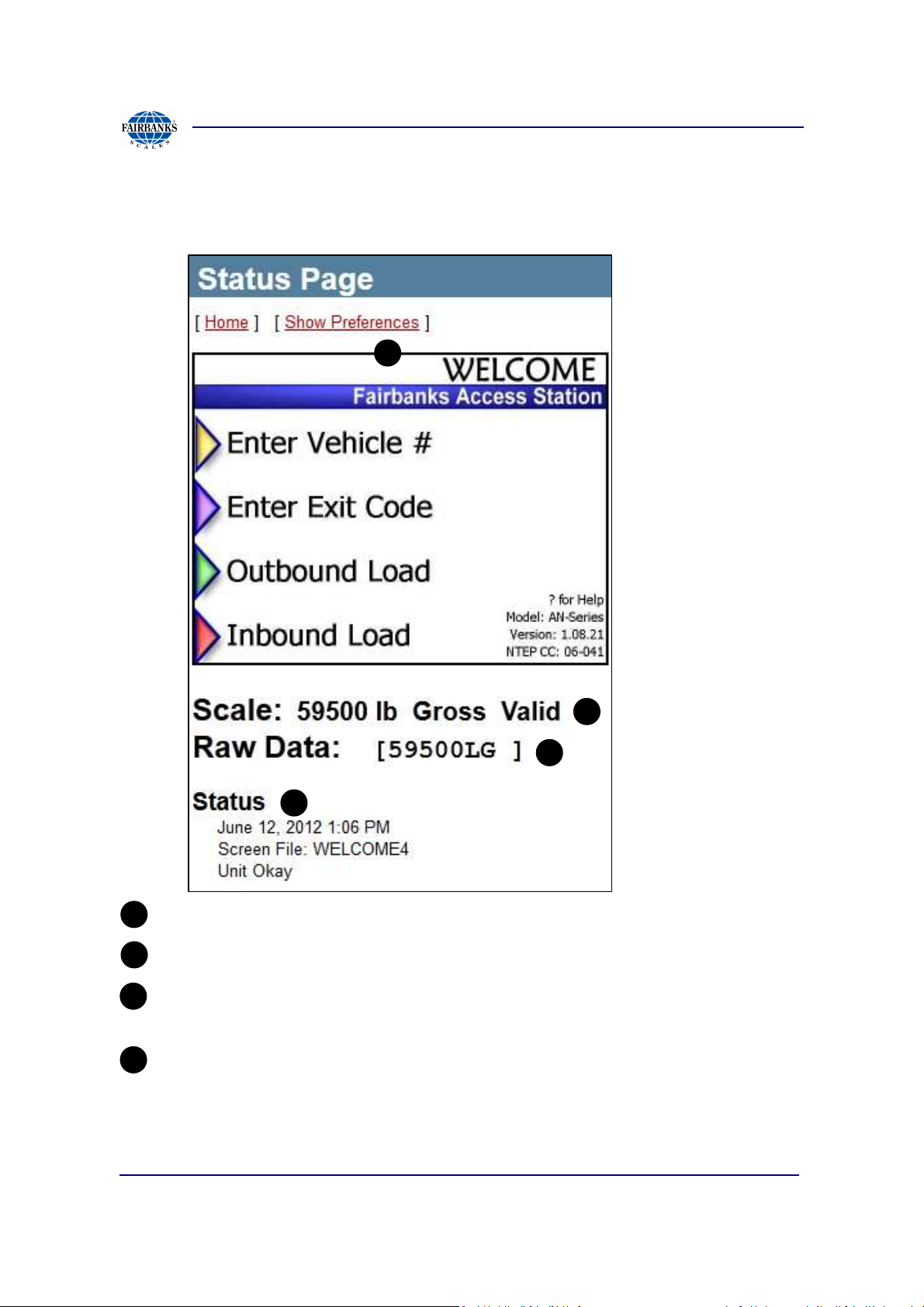
3.1.1. System Status Page
System Status Page displays Access Terminal information
Driver Screen “Welcome Screen”, shown
Scale status shown when Scale Indicator is configured.
Raw Data, shown if tracing enabled is checked under Scale Indicator
Setup (see section 3.3.6).
Status of Terminal: Unit Ok shown but can also be a starting place for
troubleshooting errors.
01/13 26 51299 Rev. 1
Section 3: Access Terminal Screens Defined
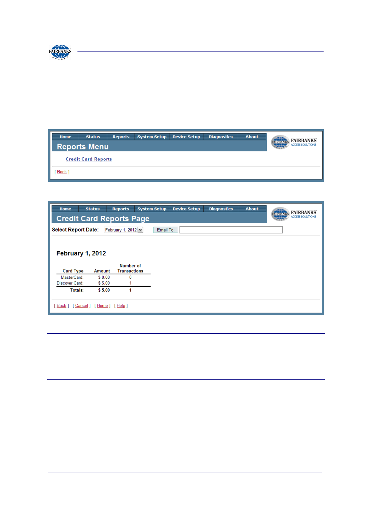
3.1.2. Reports Page
The credit card report is a daily report that includes the number and type of credit
card transactions that have occurred on individual terminals.
Note(s):
Credit Card Reports page only reflects each individual Access terminals transactions.
If there are multiple Access terminals then a better practice is using the credit card
reports from the credit card processing agent Authorize Net or running custom
reports from MatreX.
01/13 27 51299 Rev. 1
Section 3: Access Terminal Screens Defined
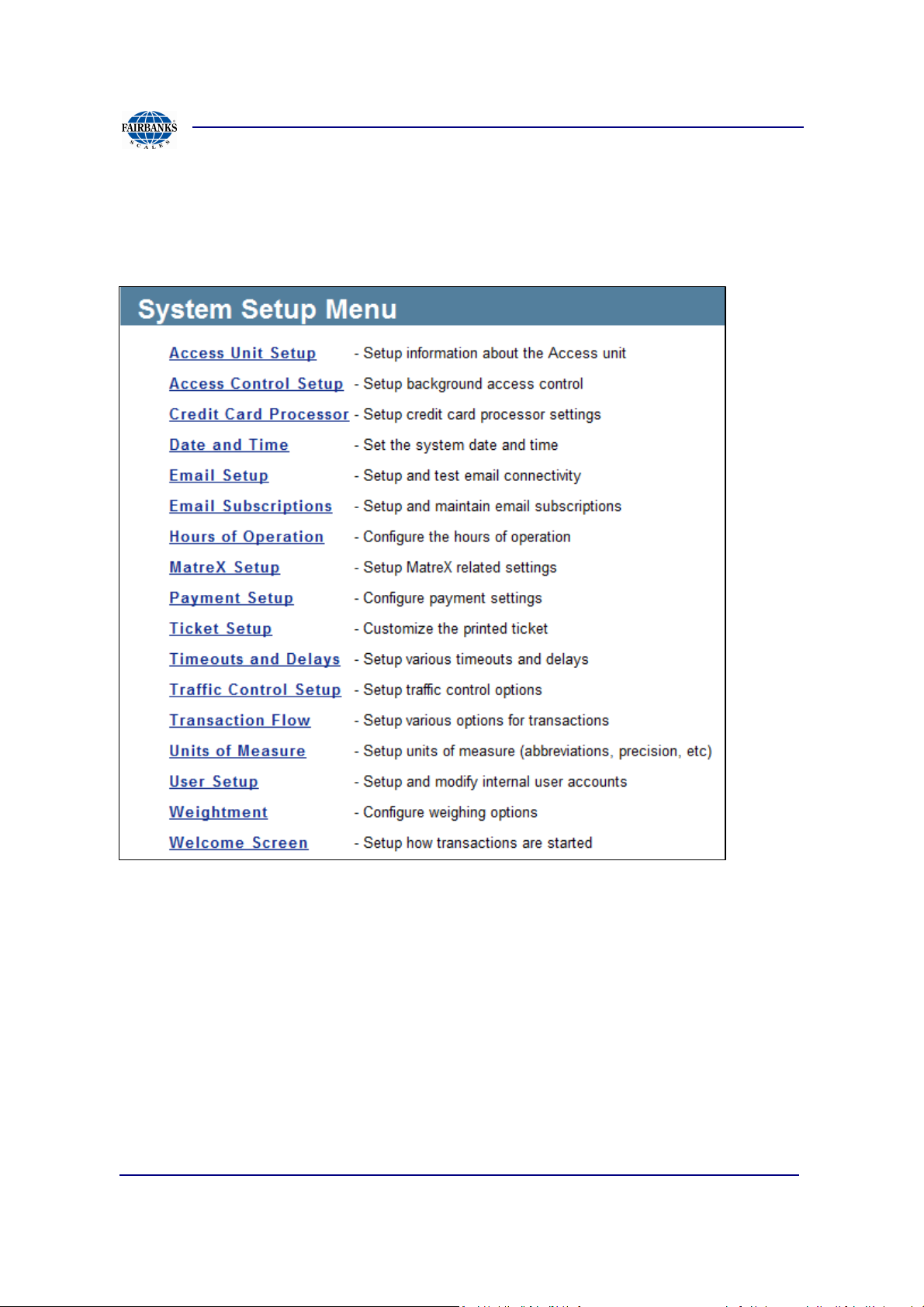
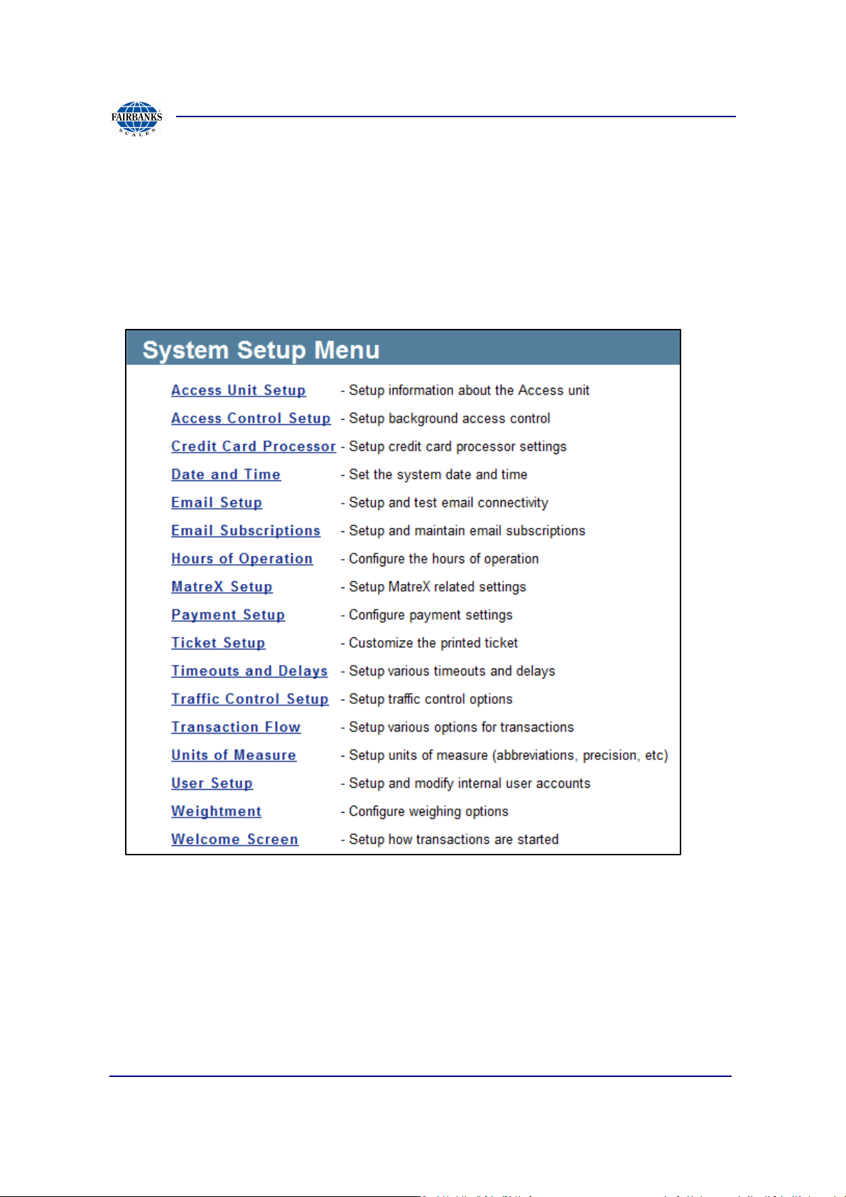
3.1.3. System Setup Menu
The below page contains the System Setup menu of the FBAS unit. The subsection
describes all of the contents currently on the Access Terminal software.
01/13 28 51299 Rev. 1
Section 3: Access Terminal Screens Defined
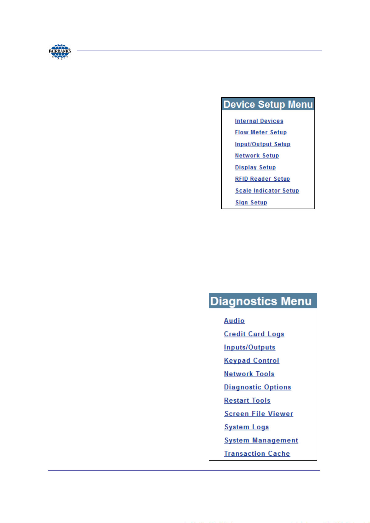
3.1.4. Device Setup
The Device Setup Menu contains multiple
information setup links. This menu’s main focus is
configuring installed devices, if any.
3.1.5. Diagnostics
The Diagnostics Menu contains viewing, event
controlling, and certain command tools to the
Access Terminal.
01/13 29 51299 Rev. 1
Section 3: Access Terminal Screens Defined
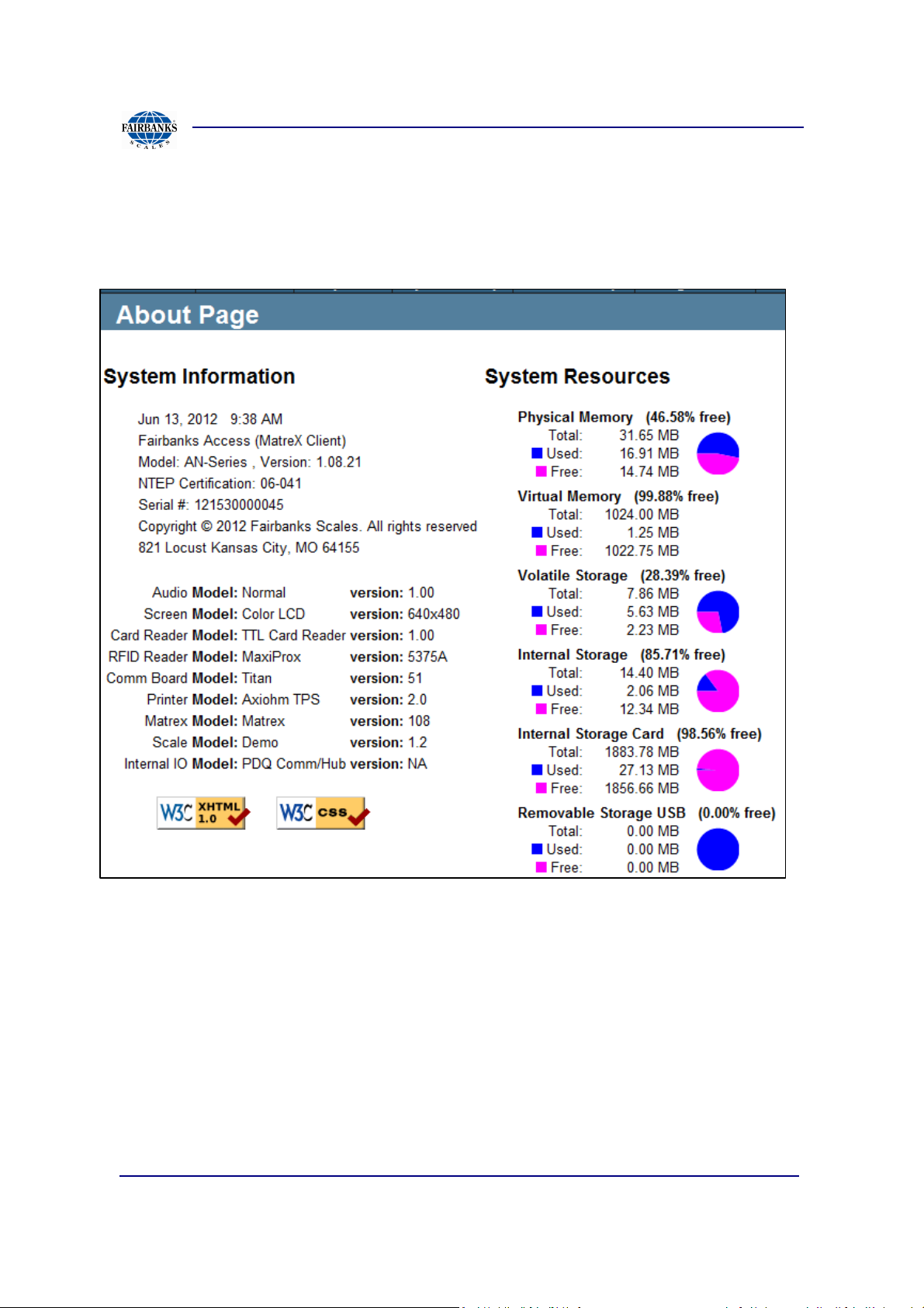
3.1.6. About
About contains system information including: installed version, enabled features, and
model/ software versions for various devices
01/13 30 51299 Rev. 1
Section 3: Access Terminal Screens Defined
3.2. System Setup
System Setup menu of the FBAS terminal controls the software specific settings.
The subsection contains usage and definitions for site specific use.
01/13 31 51299 Rev. 1
Section 3: Access Terminal Screens Defined
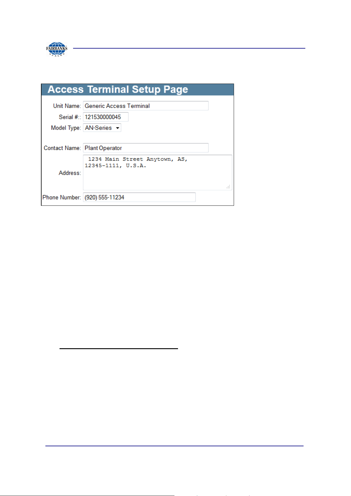
3.2.1. Access Unit Setup
The Access Terminal Setup display contains important information regarding the
access terminal. The terminal name, serial number, and model are programmed
here. The contact information for the site can also be entered to help provide a point
of contact if service is needed.
• Site Name: Labels each Access Terminal, to help identify location or purpose.
Serial #: Identifies each Access Terminal uniquely to MatreX server
• Model Type: Verify as AN Series
• Contact Name: Optional contact information for site
• Address: Address Optional contact information for site
• Phone Number: Optional contact information for site
Required entry for proper operation.
01/13 32 51299 Rev. 1

Section 3: Access Terminal Screens Defined
1
2
3
d
a
b
c
3.2.2. Credit Card Processor Settings
To allow charges for transactions at an individual terminal an account with Authroize
Net is required along with known sections 2,3 and a.
The below items are required to be set if using Authorize Net, otherwise set to none
and transactions will not be charged.
1. Select Authorize Net for processor
2. Check the accepted cards from Merchant supported range
3. Merchant Info:
a. Login will be setup from the Authorize Net account web page.
b. Transaction key will be setup from the Authorize Net account web page.
c. MD5 Value will be setup if used on the Authorize Net account web page.
d. Device type is set to Unattended Terminal
e. Market Type is set to Retail.
e
01/13 33 51299 Rev. 1

Section 3: Access Terminal Screens Defined
A B
C
A
B
C
3.2.3. Date And Time Setup
Date and Time Setup Page allow for selecting the server name and IP address
specific to the time zone.
The terminal uses the SNTP protocol to get time from the time servers.
The system will always try to use the first server in the list. If that one fails it will try
the next in the list until one works or the list runs out.
If the terminal is not keeping time correctly, an internal time server may need to be
added to the list. Contact the sites IT dept. to get the name or IP address of the time
server and replace the first entry in the list.
Date and Time
• Set manually by drop down: Current time, Set Date, Set Time, Set Time Zone
Time Servers
• Server Name- required host name of NTP time server
• IP Address- if DNS isn’t used then it is required, otherwise use for robustness
• Port- default NTP service is on 123
• Location- optional, describes location
• Status- after clicking Test it will show the state of the server test
• Show More- shows more time servers to choose from
• Set Default- sets the current time servers as the new default list
• Test- runs test against all time servers in list
Update Time
• Update time will correct any current time drift that may be in the status
01/13 34 51299 Rev. 1

Section 3: Access Terminal Screens Defined
A
B
A
B
3.2.4. Email Setup
Email Configuration
• Enable Email: If checked unit sends status of unit dependent on subscription
Test Email
Screen Capture of a failed email transmission:
Possible causes to this specific error:
• Incorrect entry in SMTP server
• If SMTP server is by name, verify DNS is working under Network Setup Page
type.
• Unit Name: Unique name to identify the specific unit in email.
• Reply To: Recipients will send to this email if replying back to email.
• SMTP Server: Email server address used for the unit to pass thru.
• SMTP Port: The default port is 25 but can be altered if necessary.
• Subject Prefix: Title of the email going to the sender
• Test Address: After successful configuration, test by sending to a test email
address
01/13 35 51299 Rev. 1

Section 3: Access Terminal Screens Defined
3.2.5. Email Subscriptions
Email Subscriptions provides a way for users to setup email notifications for various
types of events that can occur at the terminal.
To add a new email subscription, first enter the email address to include, then click
subscribe. Otherwise select an existing email address from the list.
Below shows the multiple options the subscribed user has.
After completion click on submit. To select from different subscribers click on the
drop down next to “Subscriptions for:”
01/13 36 51299 Rev. 1

Section 3: Access Terminal Screens Defined
3.2.6. Hours Of Operation Setup
Hours of operation controls when the Access Terminal is available for transactions.
Below are four options that can be toggled.
Open: The terminal is always open and allows transactions. This is the default state.
Closed: The terminal is always closed and does not allow transaction.
Maintenance: The terminal is closed and any traffic gates (configured on Traffic
Control page) are opened. No transactions are allowed.
Auto Open-Close: When in this mode the terminal can automatically close down
each night and open up each morning. When turned on, user may setup system to
automatically close (not allow transactions) and open (always allow transactions).
01/13 37 51299 Rev. 1

Section 3: Access Terminal Screens Defined
3.2.7. Matrex Setup
The terminal supports multiple server configurations which can be toggled from the
home page, and new server configurations can be created by clicking on the link Add
Another Server. Normally only one server is needed so this is a more advanced
feature.
This page only allows configuration of the servers. The actual toggling of the active
server is done from the home page of the terminal’s web interface.
01/13 38 51299 Rev. 1

Section 3: Access Terminal Screens Defined
3.2.7. Matrex Setup,Continued
SERVER CONNECTION
• Server Label: Distinguish between server connections.
• Description: Additional information about server connection.
• Server Name: Name or IP address of the MatreX server; once functioning, DO
NOT change setting. It is always recommended to use the name of the server
instead of the IP address.
• HTTP Address: Allows user to install MatreX in a different location of
processing server (non default website). Once functioning, DO NOT change
setting.
• Server URL: Shows full web address the unit connects to.
• Use Type: (previously located on Access Terminal Setup)
see Section. 3.1.3.1. ACCESS UNIT SETUP
• Company Number: The serial number of the Access Terminal. This should be
set to match the serial number on the label located inside the Access unit. This
number can affect communications with MatreX and the ability to back up and
restore.
ADVANCED SETTINGS
• HTTP Verb: DEFAULT IS POST Allows for different types of HTTP request,
do not change unless also changed in the MatreX server settings.
• HTTP Port: DEFAULT PORT IS 80
• Read Buffer Size: DEFAULT 1024
• Network Timeout: Value used to communicate with MatreX processing
server. Calls typically fail prior to value.
• Network Attempts: Attempts to connect to the MatreX server before failing.
• Retry Interval: Delay between each retry attempt.
01/13 39 51299 Rev. 1

Section 3: Access Terminal Screens Defined
3.2.7. Matrex Setup,Continued
• TRANSACTION CACHE: Cache Size: Number of transactions stored locally
on Terminal; includes completed and off-line transactions.
• Flush to Disk: How often the transaction cache is flushed to file.
• Offline Retry: Number of times the Terminal attempts connecting to the
MatreX server before failing and continuing with an off-line transaction.
• Allow Offline Trx: Select the check box for a yes response. This permits
transactions to be performed when the server is off line. The transactions are
stored in the terminal memory until the server is back online.
MESSAGES:
• Send Camera Requests: When enabled, the terminal will send additional
messages to MatreX at various stages during the transaction. These
messages allow MatreX to capture an image from any cameras
associated with this terminal for the particular stage of the transaction. If not
enabled, MatreX will only capture camera images during the Authorizing and
Processing states.
• Tracing Verbosity: Default 0; allows for additional diagnostic data. When
greater than zero, it can significantly slow down the system.
• Enable Profiling: Enables performance profiling on the messages sent to
the server.
MISCELLANEOUS:
• Maximum Item Count: This is the maximum number of items for a single
prompt that the terminal will accept. For example, if a customer has more than
1024 materials, then this count must be increased.
• Account Code Length: Maximum number of digits in an account number.
The Keypad Number (previously labeled as “cardless” number) for a vehicle
account can be less than this maximum, but the user will need to push the
enter button. Otherwise when the last digit (based on this setting) is entered,
that number is automatically looked up.
01/13 40 51299 Rev. 1
Section 3: Access Terminal Screens Defined
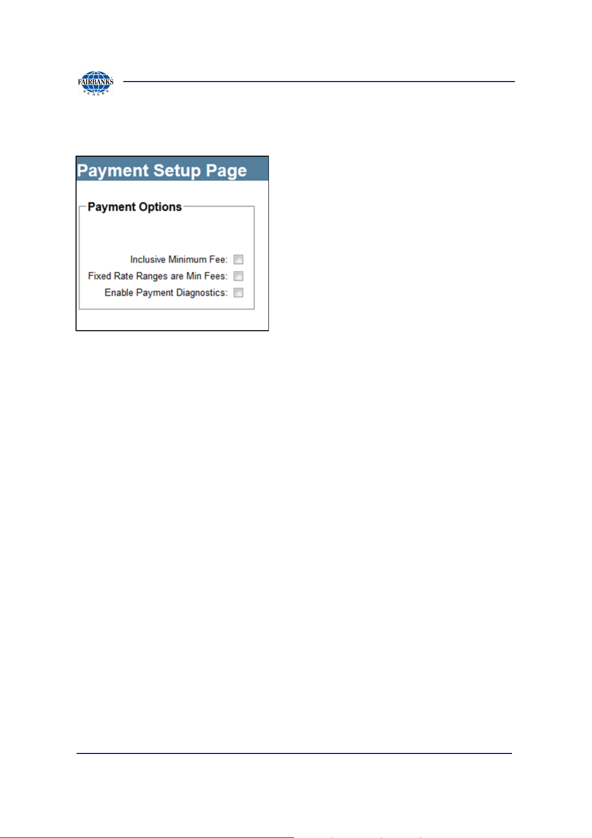
3.2.8. Payment Setup
Inclusive Minimum Fee: Normally, any additional surcharges are added onto a
minimum fee. If this option is enabled, the minimum fee is reduced to so that the
additional surcharges and the reduced minimum fee will equal the desired minimum
fee.
Fixed Rate Ranges are Minimum Fees: When this option is enabled, rate ranges
that are have on a fixed rate, the fixed rate will be treated as a minimum fee.
Enable Payment Diagnostics: This option should only be on when troubleshooting
payment calculations.
01/13 41 51299 Rev. 1

Section 3: Access Terminal Screens Defined
3.2.9. Scale Ticket Setup
Scale Ticket Setup determines when a scale ticket prints and what information to
contain.
Print Account Ticket: Controls when a scale ticket will be printed for vehicles that
have an account in MatreX. Options are Never, Always, and On Completion (default).
On Completion means that for a vehicle that weighs in and out, a scale ticket is only
printed on the weigh out stage (when the transaction is completed).
Print Off-line Ticket: Controls when a scale ticket will be printed for transactions that
are off-line. Options are Never, Always (default), and On Completion. On Completion
means that for a vehicle that weighs in and out, a scale ticket is only printed on the
weigh out stage (when the transaction is completed).
Print Cash Ticket: Controls when a scale ticket will be printed for transactions that
were paid for in cash. Options are Never, Always (default), and On Completion. On
Completion means that for a vehicle that weighs in and out, a scale ticket is only
printed on the weigh out stage (when the transaction is completed).
01/13 42 51299 Rev. 1

Section 3: Access Terminal Screens Defined
3.2.9. Scale Ticket Setup, Continued
Print Credit Card Ticket: Controls when a scale ticket will be printed for transactions
that are paid for with a credit card. Options are Never , Always (default), and On
Completion. On Completion means that for a vehicle that weighs in and out, a scale
ticket is only printed on the weigh out stage (when the transaction is completed).
Transaction / Ticket Number Label: The user can customize the label used for the
transaction or ticket number printed on the ticket. The default value is Ticket#.
Print Hauler: If checked, the name of the hauler name (owner of the vehicle) will be
printed on the scale ticket
Print Vehicle: If checked, the vehicle ID will be printed on the scale ticket. This is the
Vehicle ID in MatreX, not the ID that the driver used to start the transaction.
Print Selected Items: If checked, the names of all of the selected items from the
prompts will be printed on the scale ticket.
Print Transfer ID: The transfer ID is a number generated by the terminal based on
the serial number and the current date/time.
Print CC Pre Auth Data: When enabled, any pre-authentication data ( amount,
authorization code, transaction id) will be printed for credit card transactions. This
only applies to the pre-authentication phase of the transactions (weigh in stage).
Print Signature Line: When enabled, a line on the ticket will be printed to allow the
driver to sign the ticket.
Print Rate Details: When rate information is printed it is normally just the finally
charges, taxes and total charges. With this option enabled, additional rate information
for any selected item will be printed as well.
Print Net Weight in Both: If enabled, the net weight will be printed in both units
(pounds and tons or kilograms and metric tons).
01/13 43 51299 Rev. 1

Section 3: Access Terminal Screens Defined
3.2.9. Scale Ticket Setup, Continued
Print MatreX Units: Requires additional setup on Units of Measure Setup, see
section (3.2.13), and additional MatreX manual
#51227.
• Allows printing up to 4 custom units specific to
a material type.
These units are user defined units of measure from
MatreX. Be sure to setup the precision to use when
printing values in these units.
The ID’s for the units from MatreX will be needed.
Ticket Header: There is approximately 22 characters per line limit and allows for 4
lines. Each printed at the top of the scale ticket.
Ticket Footer: There is approximately 22 characters per line limit and allows for 4
lines. Each printed at the bottom of the scale ticket.
Off-line Note: Printed at the bottom (before the footer) of the scale ticket when the
transaction was offline.
Refund Note: Printed at the bottom (before the footer) of the scale ticket when a
cash refund could not be given.
01/13 44 51299 Rev. 1

Section 3: Access Terminal Screens Defined
3.2.10. Timeout And Delay Setup
Input Screen Timeouts:
• Enter Number: Timeout value for states that enter numbers
• Item Selection: Timeout value for states that allow selection of information
• Payment Selection: Timeout value for the select payment screen (Not Used)
• Insert Card: Timeout value for states with account or (credit cards-Not Used)
• Insert Money: Timeout value for states that accept cash (Not Used)
• Read Message: Timeout value for messages displayed to customer
• Empty Load: Timeout value for empty load (tare weight) prompt
• Empty Mixed Load: Timeout value for empty mixed prompt
• Confirm Weight: Timeout value for confirm weight screen, 0 sets an indefinite
amount of time up to 5min.
• Prompt for Start of Transaction: Timeout value for the screen that prompts the
driver if he wants to start another transaction. This screen is associated with
detecting the last long range RFID tag after a transaction was completed with
that tag. See the Long Range RFID Tag Detection section for more details.
01/13 45 51299 Rev. 1

Section 3: Access Terminal Screens Defined
3.2.10. Timeout And Delay Setup, Continued
Non-Input Screen Delays
• Get Weight: Timeout for the get weight screen. Normally as soon as the
weight is read from the scale data, the system will advance to the next screen.
This timeout will only be used if there is an issue with the scale data. The most
often cause of delay is motion on the scale. There will be a message on the
screen when motion is detected. To speed this process up you can reduce the
required readings setting in the Scale Setup page on the Device Setup menu.
Confirm there is a motion status if the require readings is set to 1 (the default
is 3).
• Display Weight: Timeout for the display weight screen. This timeout is only
used when displaying the weight not confirming the weight.
• Print Ticket: Timeout for the printing scale ticket screen. This screen will
advance to the next state once printed is completed. A longer timeout is only a
safety net or for displaying an error.
• Take Ticket: Timeout for the take scale ticket screen. This screen can be
skipped by setting the timeout to Off.
• Pull Forward: This timeout only applies if the Traffic Control feature is not
enabled. If Traffic Control is enabled, this screen is displayed for as long as a
vehicle is detected on the scale (detected by weight and possibly sensors if
configured). View Pull Forward settings under Input/Output section (3.1.4.3)
for more information.
• Cancel: Timeout value for ‘cancel’ screen
• Take Refund: Timeout value for ‘take refund’ screen
• Take Change: Timeout value for ‘take change’ screen
01/13 46 51299 Rev. 1

Section 3: Access Terminal Screens Defined
3.2.10. Timeout And Delay Setup, Continued
Long Range RFID Tag Detection-These settings control how the system handles
detecting the same long range RFID tag just after a transaction was completed
successfully with that tag.
Ignore Last Long Range RFID Tag: Duration for which the system will ignore a long
range RFID tag that matches the long range RFID tag that was used on the last
transaction. This duration starts just after the transaction ends. See the timeline
below. For example, when a vehicle with an RFID tag completes a transaction, the
vehicle will start to drive off the scale. But while driving off, the RFID tag might still be
read by the reader. In this case, the ID should be ignored, because the vehicle just
completed its transaction. But if the vehicle remains on the scale for some time, that
may indicate that the driver wishes to start the transaction again. This setting will
determine the amount of time the system will ignore the same long range RFID tag
after the end of the transaction.
Prompt for Transaction Start: Duration for which the system will prompt the driver if
another transaction should be started. So if the last long range RFID tag is detected
again during this duration, the driver will have the option of starting a transaction.
This duration starts after the duration of ignoring the tag ends
01/13 47 51299 Rev. 1

Section 3: Access Terminal Screens Defined
3.2.10. Timeout And Delay Setup, Continued
Flow Meter Timeouts
Cancel Timeout: When the volume screen is displayed an no volume was recored by
the flow meter, the transaction will be canceled after this timeout expires. Default is
off. Be sure to allow enough time for the driver to possible move the truck and
connect hoses if this timeout is enabled.
Done Pumping Timeout: Once flow is detected by the meter, the system will not
allow the driver to complete the transaction as long as there is flow. Often at the end
of pumping the flow will go to zero and then start up again. This timeout will keep the
system in this state for the configured number of seconds. Default is 15 seconds.
Auto Complete Timeout: After the flow as stopped and the Done Pumping Timeout
has expired, the driver can then complete the transaction. If the transaction is not
completed, it will be automatically completed when this timeout expires. Default is
None.
01/13 48 51299 Rev. 1

Section 3: Access Terminal Screens Defined
2
5
3 4
6
7
1
3.2.11. Traffic Control Setup
Traffic Control has two main purposes:
a) Ensure the vehicle is on the scale and that any optional conditions (i.e.
radiation detection) are met before a transaction is allowed to be started at the
terminal.
b) Control varioius traffic devices (e.g. signs, gates, lights) to properly control the
flow of traffic across the scale.
Sections of entire screen traffic control setup are displayed below. The next set of
pages describes the purpose behind each option.
01/13 49 51299 Rev. 1
Section 3: Access Terminal Screens Defined
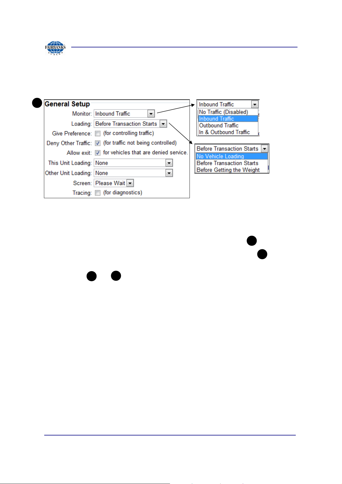
3.2.11. Traffic Control Setup, Continued
SCREEN PORTION 1 General Setup –
1
Monitor:
• No Traffic – simple in and out weighing without need to stage scale devices.
• Inbound Traffic – Enables inbound Traffic Devices, or section only.
• Outbound Traffic – Enables outbound Traffic Devices, or section only.
3
4
• In & Outbound Traffic – Enables Outbound and Inbound Traffic
or both and
3
4
Loading: Determines when the system will guide and check for vehicle on the scale.
• No Vehicle Loading
• Before Transaction Starts- Always use when Access Unit is located on Scale
• Before Getting the Weight- When Access Unit is positioned before scale
Give Preference: Used when two terminals are controlling traffic across the scale.
Each terminal is controlling traffic from one direction (inbound / outbound). Checking
one of the two will give one of the terminals a preference.
Deny Other Traffic: Generally both inbound and outbound transactions can be done
at the same Access Unit, when enabled this is not allowed. The inbound unit can
only start a transaction and the outbound can only complete it, otherwise a service
denied error will appear.
01/13 50 51299 Rev. 1

Section 3: Access Terminal Screens Defined
3.2.11. Traffic Control Setup, Continued
Allow Exit: Associated with Deny Other Traffic, allows a service denied error to be
followed with this option and will turn on any traffic devices (lights, gates). This is
recommended for unattended sites to allow the rest of the vehicles to be processed.
This Unit Loading: Used when two terminals are controlling traffic across the scale.
When the unit is in the process of loading a vehicle on the scale it will turn this output
on. This allows the other unit to know that it cannot be process a transaction.
Other Unit Loading: Used when two terminals are controlling traffic across the
scale. This unit will only read this output. The other terminal will turn this output on
when it is loading a vehicle. That tells this unit that it cannot process a transaction.
Screen: Determines what screen is displayed on the screen when the vehicle is
being loaded. In most cases Instructional should be used, and if the Access Unit is
not on the scale then None or Please Wait should be used.
Tracing: Turns on additional diagnostic data when terminal is ready or loading a
vehicle on the scale. This should not be left on unless troubleshooting an issue.
2
SCREEN PORTION 2 Detect Weight on Scale - These settings determines how a
vehicle is detected to be fully on the scale.
By weight with ##### lb/kg threshold
- If weight does not equal or exceed
set ####, then vehicle not present.
Stable after ###### readings
(change)
- Number of consecutive and
identical reads to determine if
weight is stable.
By sensors (such as photo eyes)
- Inbound and Outbound both have a
input selection and latch time in “s”.
01/13 51 51299 Rev. 1

Section 3: Access Terminal Screens Defined
3.2.11. Traffic Control Setup, Continued
Screen Capture shows Input selections
and latch times. Not shown but latch
goes from 0-30 seconds.
Timeouts –
- Timeout with no weight
If a vehicle is detected but then there is no
weight on the scale this timeout will
determine how long the system will wait
before going back to waiting for a vehicle
to arrive.
3
SCREEN PORTION 3 Inbound Traffic Devices
- Timeout with weight
If there is weight on the scale this timeout
will apply. Generally this should be set to
“None” to allow the driver all the time he
needs to start the transaction.
01/13 52 51299 Rev. 1

Section 3: Access Terminal Screens Defined
3.2.11. Traffic Control Setup, Continued
Gate: Select an output that will
be connected to a gate. Also
specify how long to keep the
output on.
Close gate: When enabled, the Access terminal will close the gate when the
selected input is detected. The input should be a sensor near the gate that will detect
the vehicle. The duration time is then used to make sure the gate is open for at least
the specified number of seconds. It also keeps the gate open until the vehicle is
detected by the sensors near the gate.
Sign: This is a sign (configured
on the Device Setup menu),
that will direct the vehicle onto
and off of the scale.
Display: This is a remote
display (configured on the
Device Setup menu), that will
direct the vehicle onto and off
of the scale.
Exit only: When enabled, the
exit only option on the sign or
display will change the device
to only direct a vehicle off of the
scale.
Staging Sign: This is a sign
(configured on the Device
Setup menu) located in the
staging area that will indicator
to any waiting drivers that the
scale is available to be used.
Staging Input: Associated with a sensor (usually a ground loop) that will detect a
vehicle in the stage area. A latching time can also be applied to the input. This is
often necessary and should be set based on the distance from the sensor to the
scale. The longer the distance the longer the latch time should be.
01/13 53 51299 Rev. 1

Section 3: Access Terminal Screens Defined
3.2.11. Traffic Control Setup, Continued
On Exit: When a vehicle is
directed to exit the scale an
additional output can be
activated. This output can be
turned on for a set duration or
until the vehicle is gone (based
on the settings in the Detect
Vehicle on Scale).
4
SCREEN PORTION 4 Outbound Traffic Devices
Options are identical to the Inbound Traffic Devices on Region but controlling
3
the opposite flow of traffic.
01/13 54 51299 Rev. 1

Section 3: Access Terminal Screens Defined
6
3.2.11. Traffic Control Setup, Continued
5
SCREEN PORTION 5 Drive By and Drive Off Alerts
These alerts occur when a transaction is not
started (Drive By) or started and not
completed (Drive Off). Each alert has the
same configuration options.
Output: When the alert occurs an output can
be turned on for the specified number of
seconds.
Alarm: The system alarm can be sounded
for a few seconds.
Attendant: If an intercom is connected with
a call option, the attendant can be alerted
through the intercom.
Email: An email will be sent to anyone
subscribed for this email.
SCREEN PORTION 6 Traffic Control Alerts
Traffic control alerts are general inputs to the terminal that will prevent a transaction
from starting and optionally from completing once started. They should be used when
the Loading setting is set to Before Transaction Starts. Up to 4 alerts can be
configured.
01/13 55 51299 Rev. 1

Section 3: Access Terminal Screens Defined
3.2.11. Traffic Control Setup, Continued
Each one will have the following options:
Input & Latch Time: This is the input that will trigger
the alert. An optional latching time can be configured
on the input as well. A latching input will remain on
for the set duration after the actual input turns off.
Error/Warning Message: This message will be displayed to the driver on the screen.
The screen option in the general settings must be set to Instructional for these
messages to be displayed to the driver. This message will also be included in the
notification if email subscription is set to monitor Traffic Control Alerts.
Output & Duration: An output can be
turned on when an alert occurs. It can be
turned on for a set duration or for the entire
duration of the input including the latch
time.
Cancel transaction on traffic alert:
This option allows correction to bad staging of equipment and positioning of input
devices such as down range or sensitive long range reader equipment.
Example Site:
• Radiation positioning was directly on the approach of the scale.
• Long Range reader was positioned down range of scale to start transaction
• Truck crept onto the scale slowly to verify tag reads.
• Threshold weight was reached so Welcome Screen, appeared to allow start of
transaction.
• Radiation detector completed scanning and found radiation but only after
transaction started. Checking this option will check after transaction starts as
well.
01/13 56 51299 Rev. 1

Section 3: Access Terminal Screens Defined
3.2.11. Traffic Control Setup, Continued
7
SCREEN PORTION 7 Loading Instructions, only applies if selection for Instructional
was selected from screen portion
1
No Vehicle on Scale: This instruction will be displayed when there is no vehicle on
the scale and no vehicle detected near the scale.
Entering, Drive On: This instruction will be displayed when a vehicle is detected
entering the scale but it is not fully on the scale yet. This can only be detected if there
are sensors to detect the vehicle, not just a weight on the scale.
Over Scale, Backup: This instruction will be displayed when a vehicle has driven
onto the scale too far. This can only be detected if there are sensors to detect the
vehicle, not just a weight on the scale.
Stop, Fully On Scale: This instruction will be displayed when the vehicle is fully on
the scale and not been by the sensors at either end of the scale.
Exiting, Drive Off: This instruction will be displayed when the transaction is complete
and the vehicle should pull forward off of the scale. This will remain until the vehicle is
gone.
Drive Off Detected: This warning will be displayed when a Drive Off/By is detected.
01/13 57 51299 Rev. 1
Section 3: Access Terminal Screens Defined
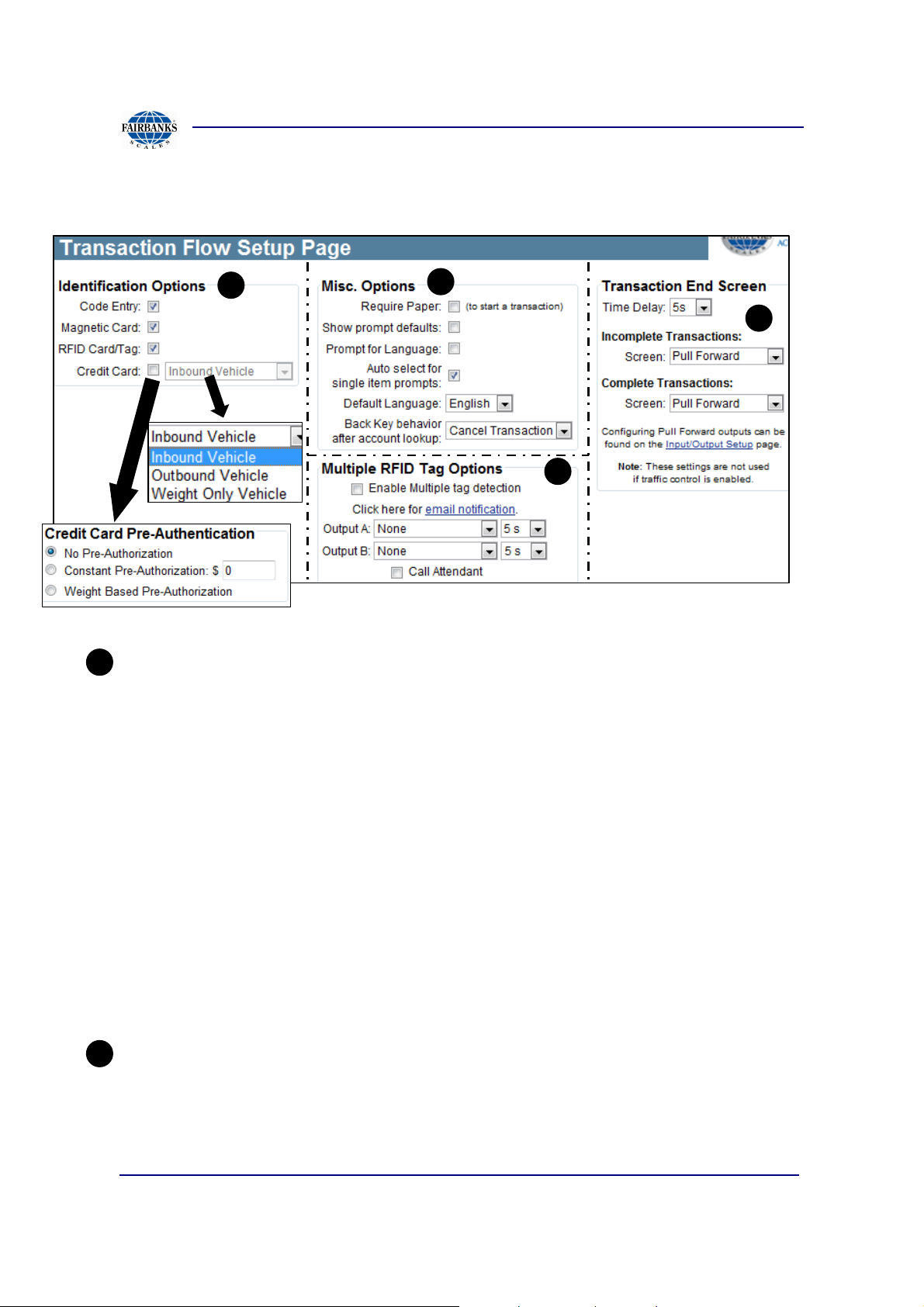
3.2.12. Transaction Flow Setup
A
B
C
A
Identification Options: Enable or disable how the driver can start transactions on an
Access Terminal.
• Code Entry: Use a specific account code to start the transaction.
D
• Magnetic Card: Allow a configured magnetic key card to start transactions.
• RFID Card/Tag: Allow short and long range RFID to start transactions.
• Credit Card:If selected a credit card will start a transaction with below options:
• Credit Card Pre-Authorization: Transactions started with a credit card must be
associated with one of the Unknown Vehicles in MatreX.
No Pre-Authorization- starts transaction, without charging preauthorization
Constant Pre-Authorization- starts with set preauthorization amount
Weight Based Pre-Authorization- starts with amount based on weight
B
Misc. Options:
• Require Paper: Transaction will not occur without printer loaded and working.
Show prompt defaults: Shows stage of transactions that are assumed
otherwise.
01/13 58 51299 Rev. 1

Section 3: Access Terminal Screens Defined
C
3.2.12. Transaction Flow Setup, Continued
• Prompt for language: Forces manual entry customers to select a language.
• Auto select for single item defaults: Less button presses when only one item to
choose.
• Default language: Forces one of three programmed languages (English,
Spanish, and French).
• Back key behavior after account lookup: sets functionality of back key on
Access Unit.
Multiple RFID tag options:
• Enable multiple tag options: Enables this detection feature. This feature should
only be used for RFID readers that broadcast multiple tags that are detected
(Pegasus).
• Email Notifications: When multiple tags are detected, an email can be sent.
Setup this notification via the Email Setup page.
• Outputs: When multiple tags are detected, two outputs can be turned on for a
specified duration.
• Call attendant: When multiple tags are detected, an attendant can be notified
via an integrated intercom.
D
Transaction End Screen:
These settings allow the last screen of a successful transaction to be changed. The
options are None, Pull Forward, and Remain on Scale. There are separate settings
for incomplete and complete transactions. Note that the pull forward outputs will only
work when Pull Forward screen is used. Also these settings are not used when
Traffic Control is enabled (Pull Forward is always used for Traffic Control).
• Time Delay: Set the delay for the end screen. This is the same timeout value
that is labeled Pull Forward on the Timeout and Delays page.
• Incomplete Transactions: Set the end screen for incomplete transaction. i.e.
the weigh in stage of a weight in/out transaction.
• Complete Transactions: Set the end screen for complete transactions.
01/13 59 51299 Rev. 1

Section 3: Access Terminal Screens Defined
3.2.13. Units Of Measure
Page configures the name, abbreviation, and precision of weight types.
The MatreX unit feature allows multiple custom units of measure to be used reflected
upon the settings in MatreX.
The Unit ID is specific to the ‘id’ given
from the MatreX web application.
Captured from the MatreX application, the predefined ID#, is shown. This ID is the
reference for the access unit
to print on scale ticket the
converted unit of measure.
References section (4.3.6)
of MatreX manual #51227
01/13 60 51299 Rev. 1

Section 3: Access Terminal Screens Defined
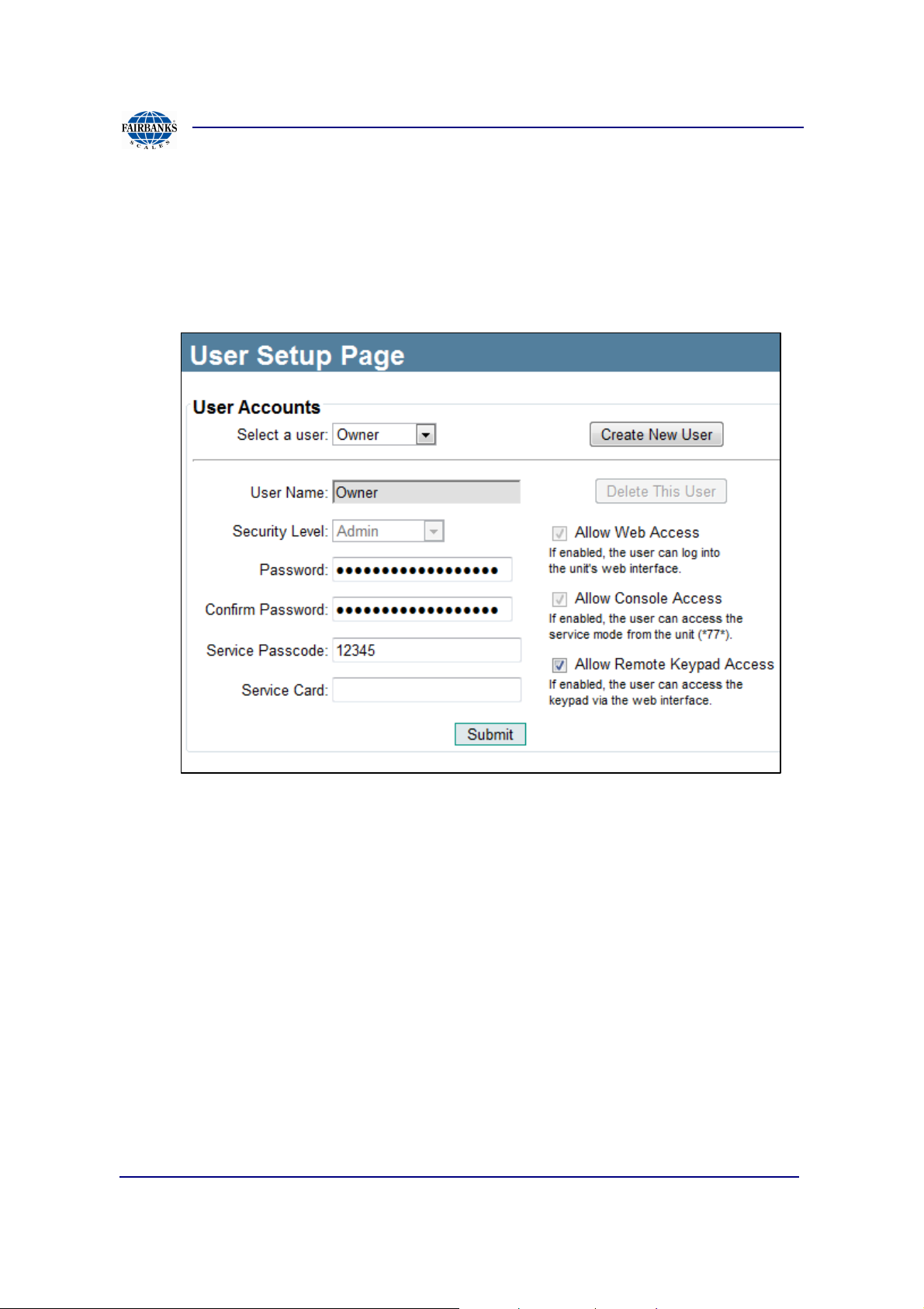
3.2.14. User Setup
User Setup allows user to create, edit, and delete user accounts for Access Terminal.
Accounts are then used to access service and diagnostic menus of Access Terminal.
USER ACCOUNTS
• Select a user: Use the drop down menu to select a current user.
• Create New User Button: Press the Create New User button to create a new
user.
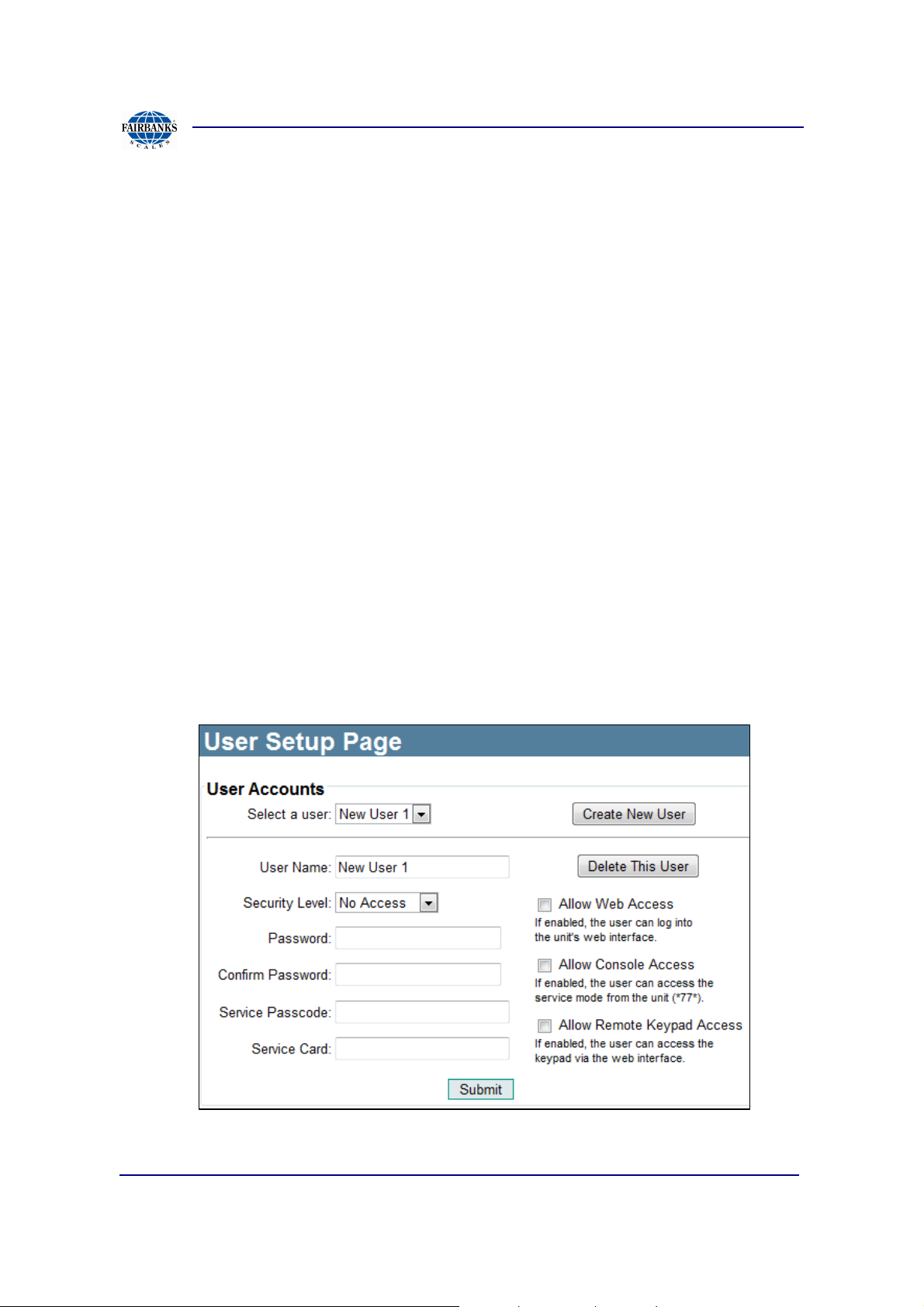
User Setup Create New User/Edit User
User Setup allows users to edit previously created users or add new users.
01/13 61 51299 Rev. 1
Section 3: Access Terminal Screens Defined
3.2.14. User Setup, Continued
USER ACCOUNTS
• Select a user: Uses the drop down menu item selected from the previous
screen.
• Username: User name of account; used when logging into Access Terminal
web interface.
• Security Level: Access level granted to user.
• No Access – A user with this security will be denied access to both the
terminal console and the terminal’s web interface. Use this level to “disable” a
user without having to permanently remove the user.
• Maintenance – A maintenance user can quickly place the terminal into
Maintenance mode. When entering into service mode at the console of the
terminal either via a *77* code or a service card, the terminal will not go into
service mode, but instead automatically toggle to or out of Maintenance mode.
It is recommended to not allow this user access to the web interface.
01/13 62 51299 Rev. 1
Section 3: Access Terminal Screens Defined
3.2.14. User Setup, Continued
• Service – A user that has full access to the service menus at the console of
the terminal and almost full access to the terminal’s web interface. This user
will be denied access to the following areas:
♦ Credit Card Reports
♦ User Setup
• Admin – A user that has full access to the service menus at the console of the
terminal and full access to the terminal’s web interface.
• Password: Only available in Edit Users Setup screen and used when logging
into Access Terminal local web interface.
• Confirm Password: A pass code used to enter service and diagnostic menus
of Access Terminal; it must be 5 numerical digits.
•
•
•
•
Allow Web Access: If enabled, user is granted web browser access to
the Access Terminal.
Allow Console Access: If enabled, the user is granted web browser access
to the service mode of the Access Terminal (*77*).
Allow Remote Keypad Access: If enabled, user is granted keyboard access
to Access Terminal.
•
01/13 63 51299 Rev. 1
Delete This User: If user selects Delete, the user selected from drop-down
menu upon pressing the Submit button will be deleted.
Section 3: Access Terminal Screens Defined
A
B
C
D
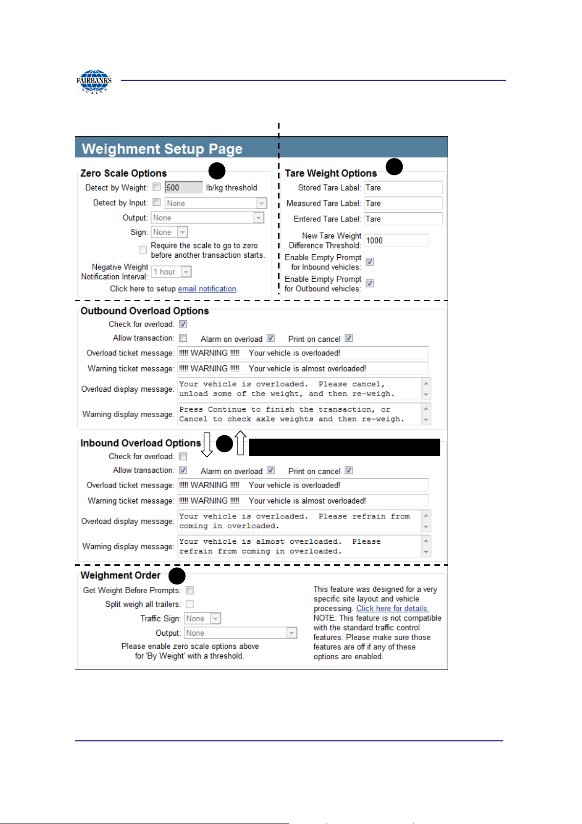
3.2.15. Weightment Setup
OVERLOAD OPTIONS SIMILAR ON BOTH
01/13 64 51299 Rev. 1

Section 3: Access Terminal Screens Defined
A
3.2.15. Weightment Setup, Continued
Zero Scale Options
The zero scale option has 3 main features:
1. Control an output or sign based on the scale being zero (or close to zero).
2. Ensures the system goes back to zero (or close to zero) before the next
transaction can start. This capability is also available by enabling Traffic
Control and vehicle loading as well. But for less complicated sites this one
could be used instead.
3. Send email notifications when the scale weight goes negative (beyond the
negative value of the threshold).
A zero scale can be detected in one of two ways by weight with a threshold. The
scale is considered zero of the weigh is greater than or equal to the negative of the
threshold weight and less than or equal to the positive threshold weight. The second
way is based on an input from the scale indicator. When the input is on, the scale will
be considered zero.
Detect By Weight: Detect a zero scale based on the weight from the scale indicator.
A weight threshold can also be set such that if the absolute value of the weight is less
then this threshold, then the scale is considered to be zero. That means if the scale
weight is negative and greater than the negative value of the threshold, the scale is
not zero.
Detect by Input: Detect a zero scale based on an input. This input is usually from the
scale indicator.
Output: An output can be turned on when the scale is zero. The output will remain on
the entire duration that the scale is zero.
Sign: Control a sign based on when the scale is zero. The sign will use the stop
signal when the scale is not zero and the go signal when the scale is zero.
Require the scale to go to zero before another transaction starts: In order to
meet NTEP requirements, the scale must go to zero before the next transaction is
allowed to start. Enabling this feature will ensure those checks are made.
Negative Weight Notification Interval: An email notification can be sent every so
often when the scale is reading a negative weight. This can be done through the
email subscripts on the Email Setup page. The frequency of the email is set here.
The default is every hour.
01/13 65 51299 Rev. 1

Section 3: Access Terminal Screens Defined
B
C
3.2.15. Weightment Setup, Continued
Tare Weight Options
Stored Tare Label: Set the text label to use for a tare weight that is stored with the
vehicle
Measured Tare Label: Set the text label to use for a tare weight that is measured or
read from the scale.
Entered Tare Label: Set the text label to use for a tare weight that is entered by the
driver.
New Tare Weight Difference Threshold: This threshold is used when a driver is
getting a new stored tare weight for a vehicle. If the new tare weight is within (+/-)
this threshold of the old stored tare weight no confirmation is needed. Otherwise if
the difference of the new and old weights is greater than this threshold, then the
driver must confirm the use of the new stored tare weight.
Enable Empty Prompt for Inbound vehicles: This setting enables the “Empty
Load” prompt. Basically this setting enables the ability for a driver to get a new
stored tare weight for the vehicle. This setting applies to only vehicles that use
stored tare weights and for vehicles that are marked as inbound vehicles in MatreX.
Enable Empty Prompt for Outbound vehicles: This setting is the same as above
but for only vehicles that are marked as outbound vehicles in MatreX.
Inbound and Outbound Overload Options
These two sections allow the terminal to check for and act on vehicles that weigh
more than their maximum gross weight. The maximum gross weight of the vehicle is
setup in MatreX on the Vehicle View/Edit page for each vehicle. The inbound and
outbound does not refer to the vehicle inbound/outbound flag. In this case it refers to
when the vehicle is arriving at the facility (inbound) or when the vehicle is leaving the
tacitly (outbound).
Check for overload: Enable this option to check for vehicles that are over their
maximum allowed weight. This maximum weight is assigned to each vehicle in
MatreX. There are separate but identical settings for vehicles that are entering
(inbound) or exiting (outbound) the facility.
Allow transaction: If enabled, the transaction will be allowed to complete. The driver
will still be warned and have the option to not complete the transaction.
Alarm on Overload: Sound Alarm
01/13 66 51299 Rev. 1
Section 3: Access Terminal Screens Defined
D
3.2.15. Weightment Setup, Continued
Overload ticket message: This is a message that will be printed on the scale ticket if
the vehicle is overloaded.
Warning ticket message: This is a message that will be displayed on the screen if
the vehicle is close to being overloaded. This requires a threshold weight to be set
along with the maximum weight in MatreX for the vehicle.
Overload display message: This is a message that will be displayed on the screen
if the vehicle is overloaded.
Warning display message: This is a message that will be displayed on the screen if
the vehicle is close to being overloaded. This requires a threshold weight to be set
along with the maximum weight in MatreX for the vehicle.
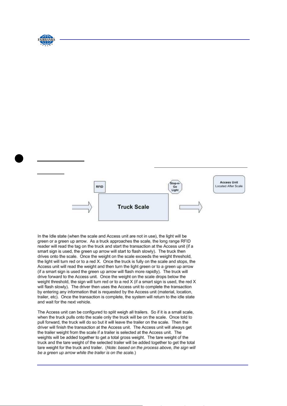
Weighment Order- Designed for a very specific site layout and vehicle processing.
The Access Unit is located ahead of the scale. View the diagram and process before
continuing.
Process:
01/13 67 51299 Rev. 1

Section 3: Access Terminal Screens Defined
3.2.15. Weightment Setup, Continued
NOTE:
Not compatible with the standard traffic control features. Please make sure those
features are off if any of these options are enabled.
Get Weight Before Prompts: Enable this option to have the terminal get the weight
before the prompts are displayed to the driver
Split weigh all trailers: This requires a trailer that does has no or little tongue weight
on the vehicle. The vehicle will pull onto the scale (but not the trailer) and start the
transaction. The system will get the vehicles weight. Then the vehicle will pull ahead
so that only the trailer is on the scale. The driver will then answer prompts at the
terminal. The terminal will then get the weight of the trailer and finish the transaction.
Traffic Sign: Select a sign to guide the driver across the scale.
Output: Select an output to control a light or gate to guide the driver across the
scale.
01/13 68 51299 Rev. 1

Section 3: Access Terminal Screens Defined
B
B
A
B A
3.2.16. Welcome Screen
Simple Mode
The above capture shows the default 4 scenarios. In Simple mode each scenario
has only 2 items, a message to appear to the driver and a behavior.
Line message visible on the display screen
Behavior selected when key pressed in line with line message
Capture shows items in Behavior
dropdown
01/13 69 51299 Rev. 1

Section 3: Access Terminal Screens Defined
A
C
A
B
3.2.16. Welcome Screen, Continued
ADVANCED OPTION
Captured shows the Welcome Screen using advanced options. Note previous simple
mode only had 2 items being the on screen text and the behavior. The advanced
mode has the type of action, text, and a behavior as a final result.
• Any chosen scenario requires at least one of the 4 steps to be populated with
a type of action and a behavior. Example Scenario 1, shows each action type
except for the “none” item, with a final outcome “behavior being Vehicle
Lookup Numeric”.
• Scenario 2 uses the Acquire ID Option, with all other steps set to none and a
behavior of “Exit Code Lookup”. If the types of actions used are only for
acquiring an ID and no other steps are used then a better approach would
have been the simple mode for this site.
Type has 5 options that scenario 1 shows in steps 1,2,3,4 and
“None” in Scenario 2.
• None: no action is taken
• Custom Input: This condition will wait for the specified
input to turn on (or off) before going on to
the next step.
• Button Press: This condition will wait for the button associated with the
scenario (selection key) before going on to the next step.
• Scale Weight:
Checks for a certain amount of
weight to be on the scale before
going on to the next step.
01/13 70 51299 Rev. 1

Section 3: Access Terminal Screens Defined
B
C
3.2.16. Welcome Screen, Continued
• Acquire ID: This is the final step after all other conditions are met. At this point
the driver can enter or present vehicle identification.
Type is text and limited to the characters used on a single
line on the display
Behavior list shown below, this is the expected
outcome of the staging area.
Vehicle Lookup (Numeric) / (Alpha) / (Card): With this option the driver identifies
the vehicle via the keypad (numeric or alpha-numeric) or a card (magnetic swipe or
RFID card). The transaction will be based on how the vehicle is configured in MatreX.
NOTE: Any time a number is keyed in or a card is swiped without making a selection
at the welcome screen this option will be used.
(Inbound) / (outbound) Load Weigh In/Out: When using MatreX, this option is used
for vehicles that do not have an account. Transactions started by selecting this option
will be associated with the Unknown Inbound Vehicle or the Unknown Outbound
Vehicle in MatreX. This type of transaction will also generate an exit code that is used
during the weigh out stage of the transaction. When integrated with Soft-Pak, this will
generate a list of vehicles for the driver to choose from. When integrated with
Paradigm, this will be associated with Paradigm's cash customer.
Vehicle Weigh Only: When using Matrex, this option is used for vehicles that do not
have an account and are not doing a typical transaction. This case the vehicle is just
getting a weight from the scale. Depending on how MatreX is configured, the driver
may need pay before getting this weight.
Exit Code Lookup: When this option is select, the terminal will prompt for an exit
code. This is used to complete transactions for Unknown Vehicles in MatreX. NOTE:
The exit code can be entered at the welcome screen without selecting this option.
01/13 71 51299 Rev. 1

Section 3: Access Terminal Screens Defined
3.2.16. Welcome Screen, Continued
Reweigh Code Lookup: When this option is select, the terminal will authorize a reweigh. The re-weigh code is given out for vehicles that only get a weight from the
scale instead of a typical transaction.
Work Order (Numeric) / (Alpha) / (List): A work order is a type of transaction that is
related to a particular job. There is an ID for this job and once completed it cannot be
done again. A work order can be entered via the keypad as an alpha-numeric or
numeric value. It can also be selected from a list of outstanding work orders. This
option is currently only available with Soft-Pak integration.
Access Control Only: If the vehicle only needs access control to a location, this
option is used. Identification must still be provided in any format (keypad, card, etc).
Restart Conditions: The restart conditions are used to put all scenarios back into its
initial step. For example, if the conditions are triggered based on scale weight and
vehicle drives across the scale but does nothing at the terminal, the terminal should
restart the conditions when the vehicle leaves the scale. The two options are Custom
Input and Scale Weight as described above.
01/13 72 51299 Rev. 1

Section 3: Access Terminal Screens Defined
3.3. Device Setup Menu
The Device Setup Menu contains multiple information setup links. This menu’s main
focus is configuring installed devices, if any.
The following section contains the following pages.
• Internal Devices
• Flow Meter Setup
• Input/output Setup
• Network Setup
• Display Setup
• RFID Reader
• Scale Indicator
• Sign Setup
01/13 73 51299 Rev. 1
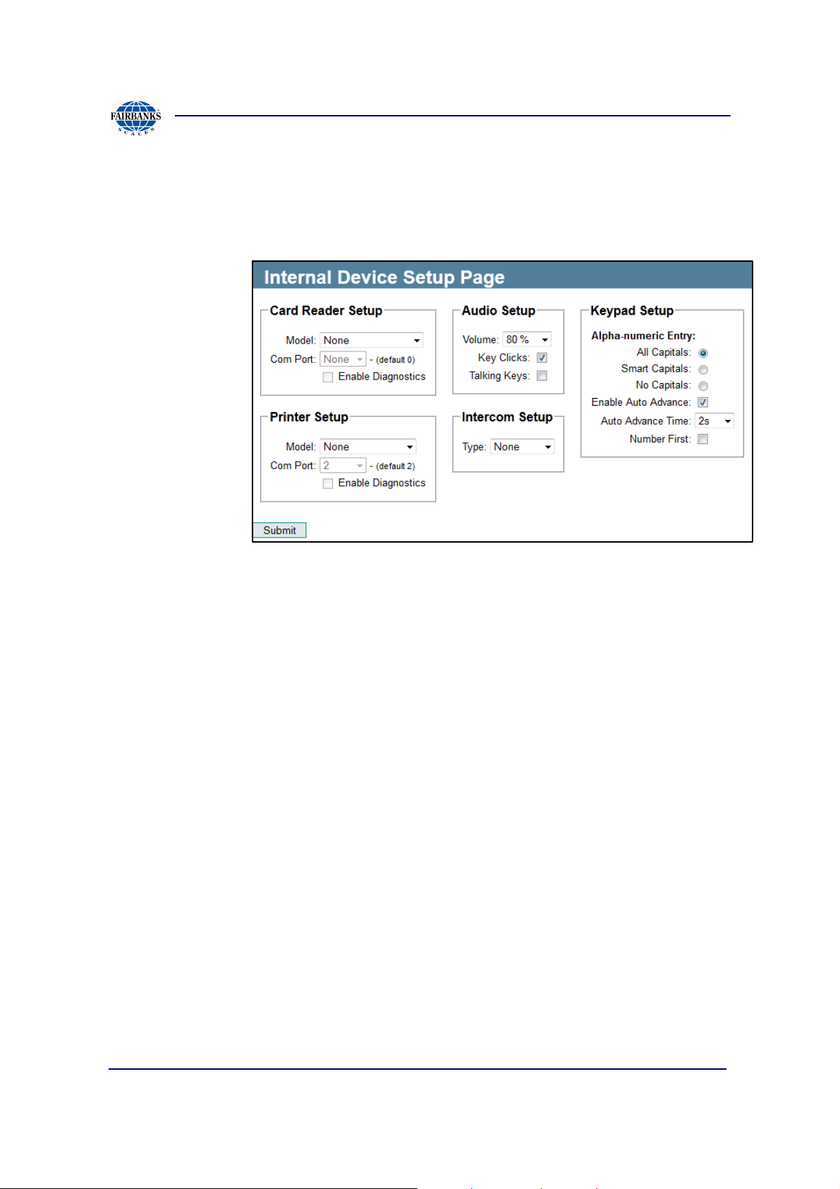
Section 3: Access Terminal Screens Defined
3.3.1. Internal Devices
Internal Devices Setup permits programming for a card reader, printer, intercom,
audio, and keypad setup in the software.
Card Reader Setup: Uses TTL communication instead of a serial port.
Printer Setup- Default set to COM Port 2, can also use ports: 3 and 4 if
available.
Audio Setup
• Keypad Clicks: Turns on/off audio clicks for any pressed key on keypad
• Talking Keys: Turns on/off audio for any pressed number keys on keypad;
example: when 4 number key is pressed, a verbal audio annunciates four
01/13 74 51299 Rev. 1

Section 3: Access Terminal Screens Defined
3.3.1. Internal Devices, Continued
Key Pad Setup
• Capitals: Determines how capitals are used for alphanumeric entry. Options
include: All Capitals, Smart Capitals (1st character of line and after a space is
capitalized), and No Capitals.
• Enable Auto Advance: If selected, cursor automatically advances to next
character (after a period of time) when a key is pressed
• Auto Advance Time: Time used for auto advanced feature
• Number First: When enabled the number will come up first instead of the alpha
character. For example, normally when entering alpha-numeric data pressing the #2
key will show A, pressing it again will show B, again and it will show C, and again
after another press it will show the number 2. But when this is checked, the number
2 will be show first.
Intercom Setup: Intercom Setup allows user to select type of intercom connected to
system; set to pulse if using the internal intercom system.
01/13 75 51299 Rev. 1

Section 3: Access Terminal Screens Defined
3.3.2. Input/Output Setup
Input/ Output Setup page includes 6 different sections that are broken up in the
following labels (A, B, C, D, E, and F).
01/13 76 51299 Rev. 1
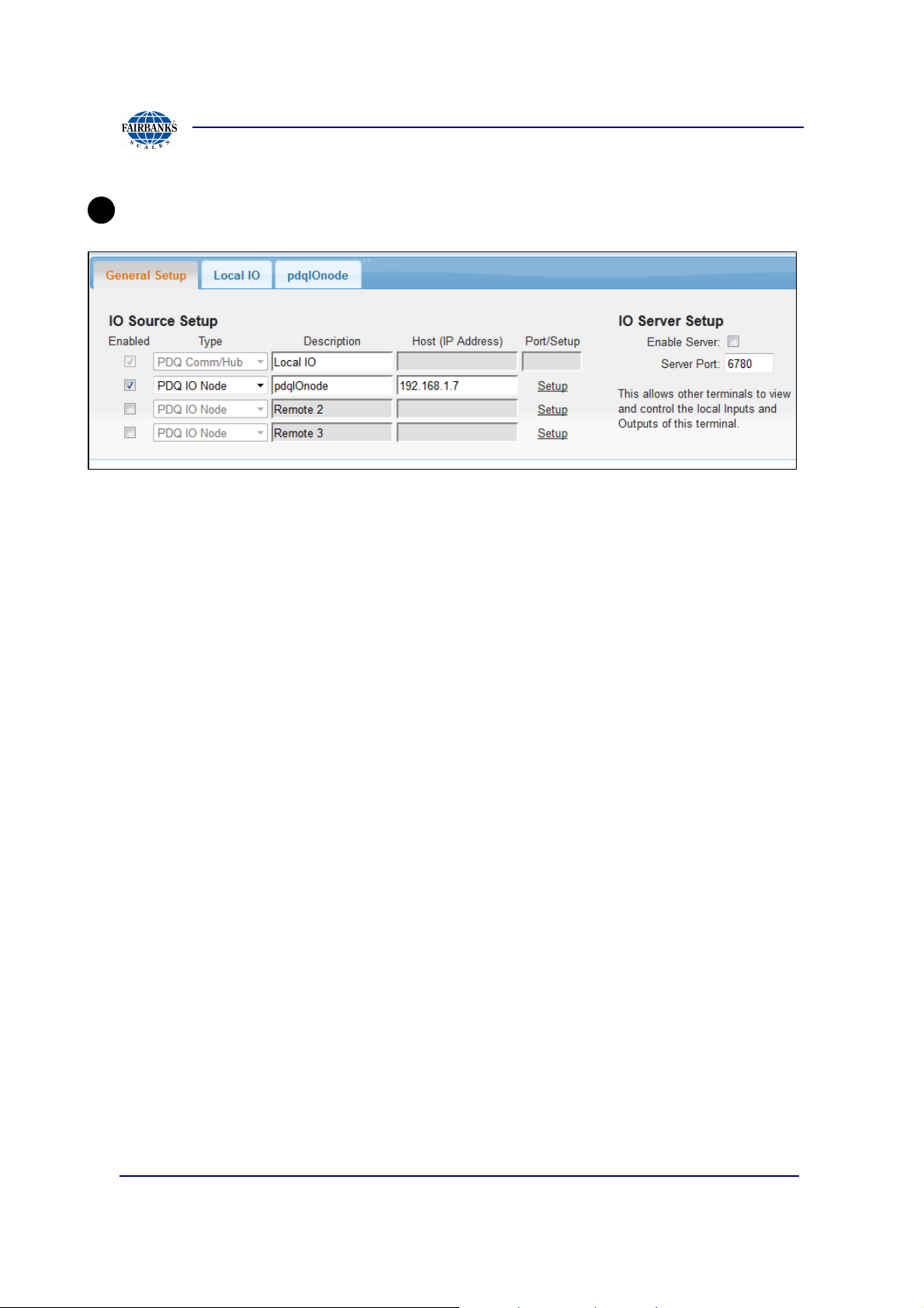
Section 3: Access Terminal Screens Defined
A
3.3.2. Input/Output Setup, Continued
General Setup
• Enable Source: IO data can come from a number of locations. The first
source is the IO that is available internally within the Access terminal.
Additional IO can come from other Access terminals or other IO devices. Up to
three additional devices can be configured.
• IO Source Type: This is the type of IO device the IO is coming from. PDQ IO
Node is supplied as the main IO board with a default of 10 controllable
outputs. Modbus IO is any device that has IO via the modbus protocol. The IO
Lan D4 is a modbus based device.
• Description: Provide a short description of the IO source. This will be used on
this page as well as the IO diagnostic page to identify the IO source.
• Host: Most external sources of IO are accessed via the network. Provide the
host name or IP address of the device that has the IO.
• Port / Setup: For network based devices provide the TCP/UDP port to
connect to on the device for IO data. For modbus based devices a setup link
will be provided to configure how the terminal reads the IO via the modbus.
IO Server Setup
• Enable Server: When this option is enabled, other terminals can access the
IO on this terminal.
• Server Port: Provide a UDP port number that will provide the IO data from this
terminal.
01/13 77 51299 Rev. 1
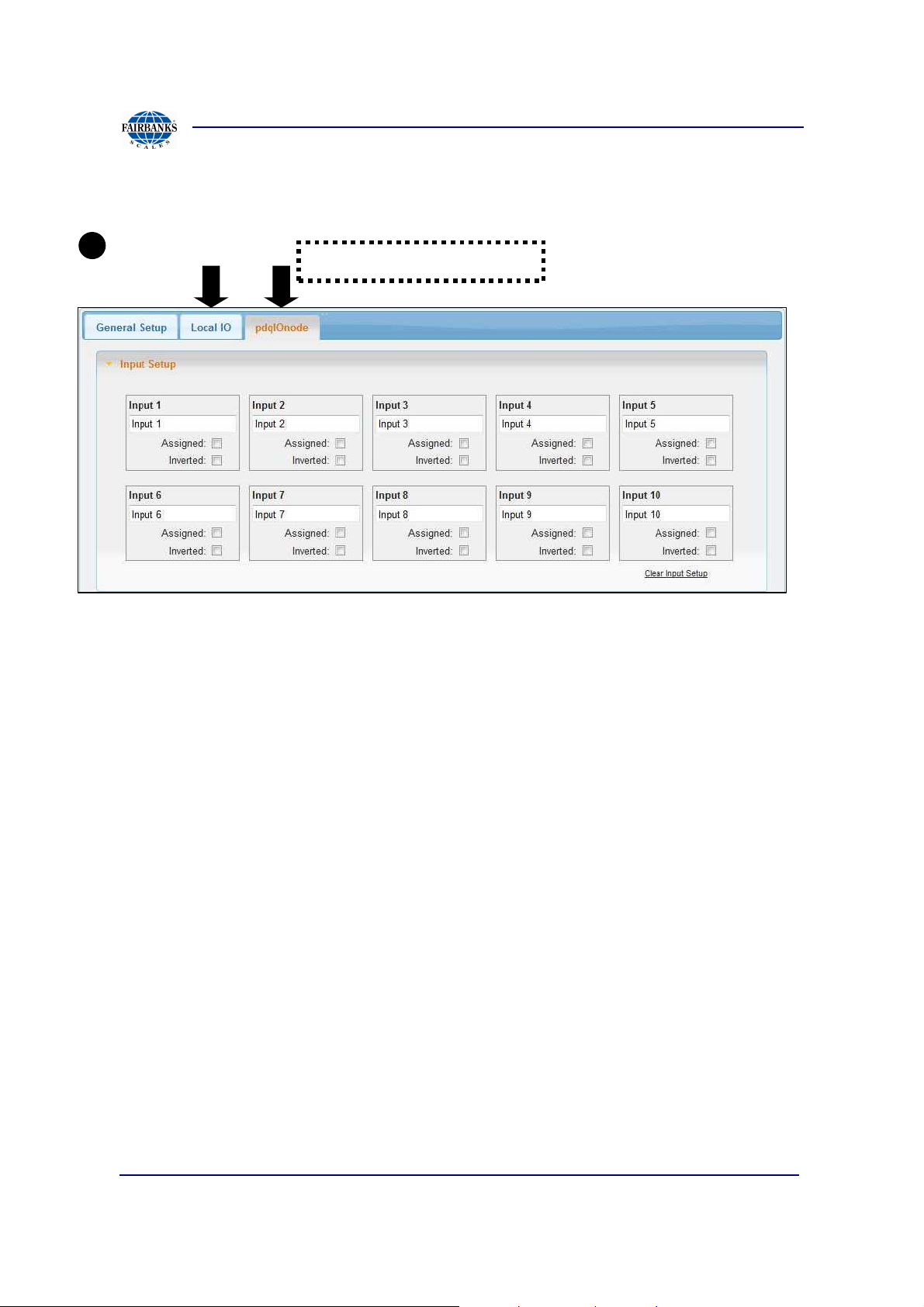
Section 3: Access Terminal Screens Defined
B
3.3.2. Input/Output Setup, Continued
Input Setup
IO Source tab selection
• IO Source: Select the input source that you want to configure from the
selection of configured tabs. The number of inputs will vary based on the IO
source.
• Input Label: Enter a brief label. This will be displayed on the diagnostic page
and any drop-down lists for selecting inputs.
• Assigned: Check this option if the input is assigned to an action. It is
recommended to check this setting whenever the input is being used. The
input should also be given a short label as well. Once “assigned”, then the
label will be used instead of just the generic “Input 1” in dropdown lists.
• Inverted: If the input is inverted, enable this option to invert it back. For
example, if the input is normally on and turns off during an action, then enable
this option so that the input will be normal (normally off).
01/13 78 51299 Rev. 1
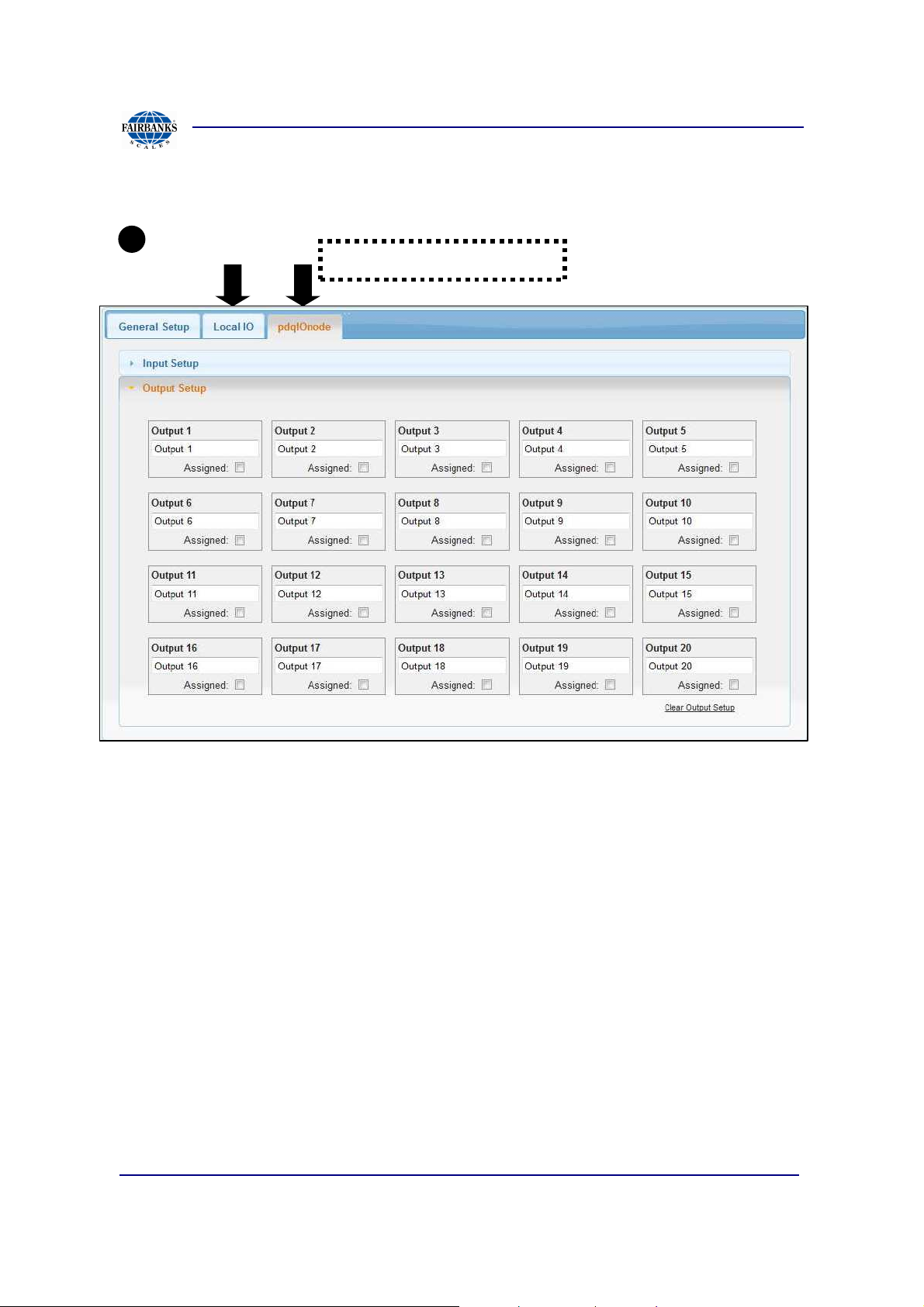
Section 3: Access Terminal Screens Defined
C
3.3.2. Input/Output Setup, Continued
Output Setup
IO Source tab selection
• Output Source: Select the input source that you want to configure from the
selection of configured tabs. The number of outputs will vary based on the IO
source.
• Output Label: Enter a brief label. This will be displayed on the diagnostic
page and any drop-down lists for selecting outputs.
• Assigned: Check this option if the output is assigned to an action. It is
recommended to check this setting whenever the output is being used. The
output should also be given a short label as well. Once “assigned”, then the
label will be used instead of just the generic “Output 1” in dropdown lists. This
output will be highlighted in the IO diagnostics as well.
• Initially On: Enable this option if the output should be on when the system is
started.
01/13 79 51299 Rev. 1

Section 3: Access Terminal Screens Defined
D
3.3.2. Input/Output Setup, Continued
Pull Forward Outputs
The pull forward outputs are turned on for the duration of the Pull Forward screen at
the end of the transaction. Typical setup is for Always and any Any Vehicle so the
output will always trigger during the Pull Forward screen. To control the output
conditionally use the conditions described below.
• Transaction Stage: This refers to the weigh in/out process. The On Start
option refers to weigh in stage, On Complete option refers to the weigh out
stage.
• MatreX Vehicle Flag: This refers to the type of vehicle in MatreX as to
whether it is marked as an Inbound or Outbound vehicle.
• Output: Select the output to turn on during the Pull Forward screen. The
duration of the Pull Forward screen is configured on the Timeout and Delay
Setup page.
• Alternate Outputs: Enable this option to alternate between the two outputs for
each transaction.
01/13 80 51299 Rev. 1

Section 3: Access Terminal Screens Defined
E
3.3.2. Input/Output Setup, Continued
Prompt/Output Mapping
Prompt Output Mapping allows the driver prompt selections to trigger an output
specific to a driver response at the Access Terminal.
Prompts
There are six prompt types; Customer, Material, Activity, Trailer and Job which
require a group setup for any of the 6 to allow an output to map a behavior.
Compare
Comparison can be made by three types; Code, Name and ID.
Data
The data field is user entered to match one of the comparison types.
Output
Output list all available output locations that can be toggled for a specific prompt.
Stage
There are six possible stages; Any, Monitoring, Pull Forward, Remain on Scale, End
of Stage 1, End of Stage 2.
01/13 81 51299 Rev. 1

Section 3: Access Terminal Screens Defined
3.3.2. Input/Output Setup, Continued
Stage:
• Any
• Monitoring
• Pull Forward
• Remain on Scale
• End of Stage 1
• End of Stage 2
Duration:
Determines how long each set output will stay active.
01/13 82 51299 Rev. 1

Section 3: Access Terminal Screens Defined
F
3.3.2. Input/Output Setup, Continued
Output Cloning
Up to 3 outputs can be enabled from an initial trigger output. When the trigger is
turned on or off the clone outputs mimics the trigger outputs behavior with the benefit
of trigger duration to the cloned response.
01/13 83 51299 Rev. 1

Section 3: Access Terminal Screens Defined
Labeled
I
nternet
Labeled
VLAN1,2,3
3.3.2. Configurations for PDQ IO node
Note:
There are 2 network hubs located on the com hub board, both are located on the
bottom right edge of the board and labeled; (Internet) hub1, and (Vlan1, Vlan2,
Vlan3) hub2.
The (2) Network Hub connections allows multiple devices to be connected on two
separate subnets allowing privacy from the rest of the local area network. The only
way for the Access Terminal to recognize this is using the dual homing feature under
section Secondary IP Settings.
A common setup to allow multiple devices to be used by the Access Terminal would
be to place:
- (Internet) the IO node connection in the internet socket
- (VLAN1, 2, 3) the Local Area Network (Ethernet) and auxiliary network
devices (IP cameras etc…) in the VLAN sockets
1. Verify network connectivity from one of 2 network hubs on the com board has
been made.
(Using a standard (1) IO node setup)
• Place the IO node cable in the Internet socket.
• Place the network cable for the site in VLAN1, 2, 3.
Network Hub 1
Network Hub 2
Network Hub 2
Network Hub 2
01/13 84 51299 Rev. 1

Section 3: Access Terminal Screens Defined
a a b c e
3.3.2. Configurations For PDQ Io Node, continued
2. Verify network communications setup includes enabling of dual homing.
To locate section go to Home >> Device Setup >> Network Setup.
a. Insert subnet of 192.168.1.x where x is the last octet of the Titan FBAS IP
address.
b. Insert subnet mask of 255.255.252.0
c. Click Submit to save changes
3. Verify Input/output setup including the PDQ IO Node device.
To locate section go to Home >> Device Setup >> Input/ Output Setup.
a. Enable checkbox and select PDQ IO Node
b. Create a description ex. pdqIonode.
01/13 85 51299 Rev. 1

Section 3: Access Terminal Screens Defined
g
3.3.2. Configurations For PDQ Io Node, continued
c. Insert factory default IP of 192.168.1.7
d. Click Submit to save changes.
e. Locate and click on the Setup link.
f. Click Ok to the unsaved changes dialogue box.
g. Verify connectivity by locating and clicking on Ping.
4. Set the IO node labels for both i/o.
a. To locate section go to Home >> Device Setup >> Input/ Output Setup.
5. Select the I/O device labeled “pdqIOnode” from the above tab region
*note the pdqIOnode tab reflects a custom entry to describe the PDQ IO node.
01/13 86 51299 Rev. 1

Section 3: Access Terminal Screens Defined
c
a
b
d e
3.3.2. Configurations For PDQ Io Node, continued
6. Select from I/O regions: a, b, c, d, e
a. Input Setup
b. Output Setup
c. Tab 1 Pull Forward Outputs
d. Tab 2 Prompt/Output Mapping
e. Tab 3 Output Cloning
01/13 87 51299 Rev. 1

Section 3: Access Terminal Screens Defined
A
C
B
A
3.3.3. Network Setup
Primary IP Settings
• DHCP: The system can be setup to use DHCP to get an IP address or
configured to use a static IP address that is provided by the network
administrator. Note that although DHCP works, there is no way to assign a
network host name to the terminal. So if the IP address changes it may be
difficult to find the terminal on the network.
• IP Address: When DHCP is enable, the IP address assigned to the terminal
will be displayed. Otherwise enter the IP address that the terminal should use
on the network.
• Subnet Mask: When DHCP is enabled, the subnet mask assigned to the
terminal will be displayed. Otherwise enter the subnet mask that the terminal
should use on the network.
• Gateway: When DHCP is enabled, the default gateway assigned to the
terminal will be displayed. Otherwise enter the default gateway that the
terminal should use on the network.
01/13 88 51299 Rev. 1

Section 3: Access Terminal Screens Defined
B
C
3.3.3. Network Setup, Continued
• Preferred DNS: When DHCP is enabled, the preferred DNS assigned to the
terminal will be displayed. Otherwise enter the preferred DNS that the terminal
should use on the network.
• Secondary DNS: When DHCP is enabled, the secondary DNS assigned to
the terminal will be displayed. Otherwise enter the secondary DNS that the
terminal should use on the network.
TCP Settings
• Keep Alive Time: The parameter controls how frequently TCP tries to verify
that an idle connection is still intact by sending a keep alive packet. If the
remote computer is still reachable and functioning, the remote computer
acknowledges the keep alive transmission. By default, keep alive packets are
not sent. A program can turn on this feature on a connection.
• Keep Alive Interval: This parameter determines the interval that separates
keep alive retransmissions until a response is received. After a response is
received, Keep Alive Time again controls the delay until the next keep alive
transmission. The connection is aborted after the number of retransmissions
that are specified by Data Retransmissions are unanswered.
• Data Retransmissions: This parameter controls the number of times that
TCP retransmits an individual data segment (non-connect segment) before it
aborts the connection. The retransmission timeout is doubled with each
successive retransmission on a connection. It is reset when responses
resume. The base timeout value is dynamically determined by the measured
round-trip time on the connection.
Secondary IP Settings
• Enable Dual Homing: Dual homing allows the terminal to have two IP
addresses assigned to it. This is useful if the terminal needs to communicate
with devices on separate networks (subnets). This is required to be enabled
and configured if using the I/O node accessory. See sect. 5.2.3 for setup
instructions.
• IP Address: Secondary IP address that the terminal should use on the
network.
• Subnet Mask: Secondary subnet mask that the terminal should use on the
network.
01/13 89 51299 Rev. 1
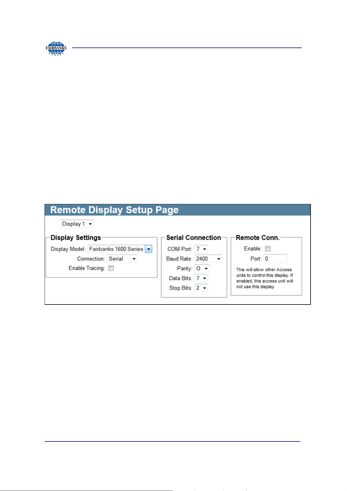
Section 3: Access Terminal Screens Defined
3.3.4. Remote Display Setup
Remote displays communicate weight data from the Unattended Terminal to a
external display. The two display.s currently supported include the Rice Lake
LaserLight and the Fairbanks 160x series.
Fairbanks 1605/1605T
Below are the features included with the Fairbanks 1600 series. Default factory
settings include Serial settings: 2400 / O / 7 /2
• Choose the “Display” number on the dropdown that relates to the unit.
• Select “Display Model” as Fairbanks 1600 Series.
• Choose Connection as Serial, then setup serial connections 2400/O/7/2 from
factory defaults, or other settings dependent upon display setup.
01/13 90 51299 Rev. 1
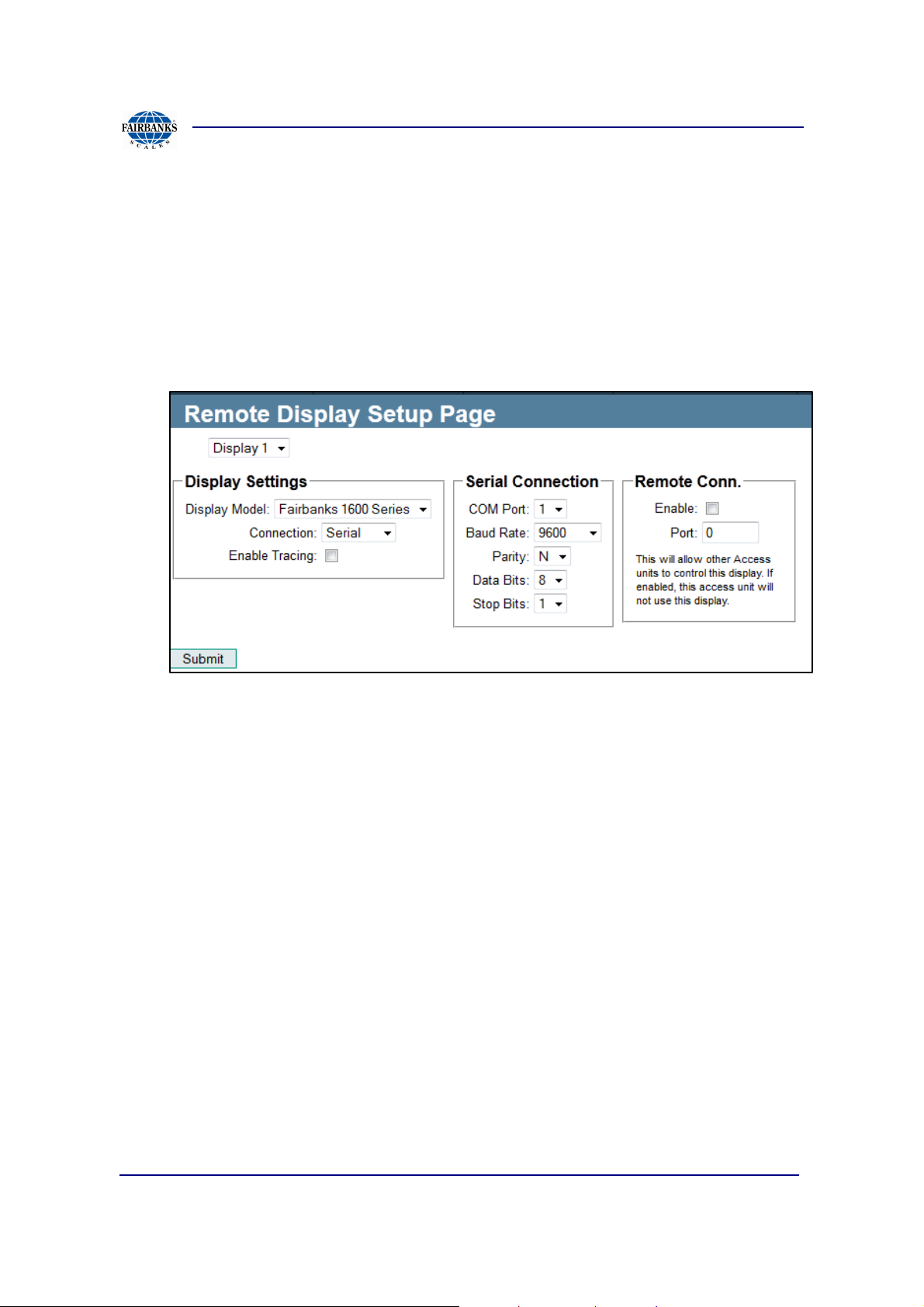
Section 3: Access Terminal Screens Defined
3.3.4. Remote Display Setup, Continued
To use the additional sign option on the 1605T- (Shown again under Sign Setup)
• Choose the “Sign” number on the dropdown that relates to the unit.
• Select “Sign Type” as Fairbanks Display 1605T.
• Select “Display” to match the same value used from the Display Setup.
01/13 91 51299 Rev. 1

Section 3: Access Terminal Screens Defined
3.3.4. Remote Display Setup, Continued
Rice Lake LaserLight
Below are the features included with the Rice Lake setup, serial connection settings
vary on dependency of the display.
01/13 92 51299 Rev. 1
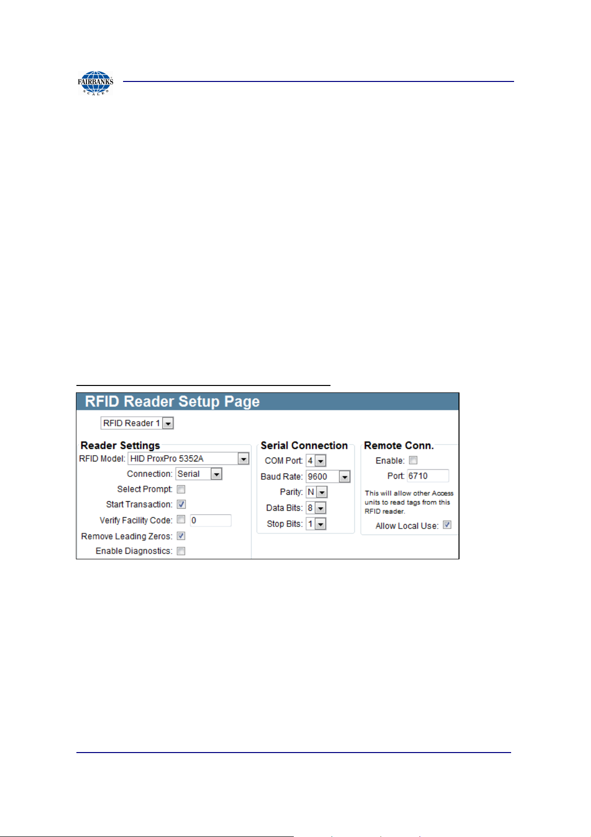
Section 3: Access Terminal Screens Defined
3.3.5. Rfid Reader Setup
Common to the options of the RFID Reader include the below, other items are
specific to the RFID Model selected.
• RFID Model: Select the type of RFID reader to configure. Certain readers will
have different configurations and that will be noted below.
• Start Transaction
• Remove Leading 0: Many RFID cards will send the card number along with
leading zeros. Typically, these zeros should not be part of the card number
and need to be removed. By default enable this option.
• Enable Diagnostics: When enabled additional diagnostic data about the RFID
reader will be available
• Serial Connection Setup
• Enable Port for Remote Connection
RFID Model: HID and AWID Proximity Readers
Select Prompt: Enable this option if this reader is going to be used to select items
from a prompt. The RFID card numbers must match the item codes that are sent
from MatreX.
Start Transaction: Enable this option if this reader is used to start a transaction by
identifying a vehicle.
Verify Facility Code: Enable this option and enter a facility code to verify. HID and
AWID proximity cards contain a facility code as well as a card number. To only allow
certain cards to be used, you can require a specific facility code.
01/13 93 51299 Rev. 1
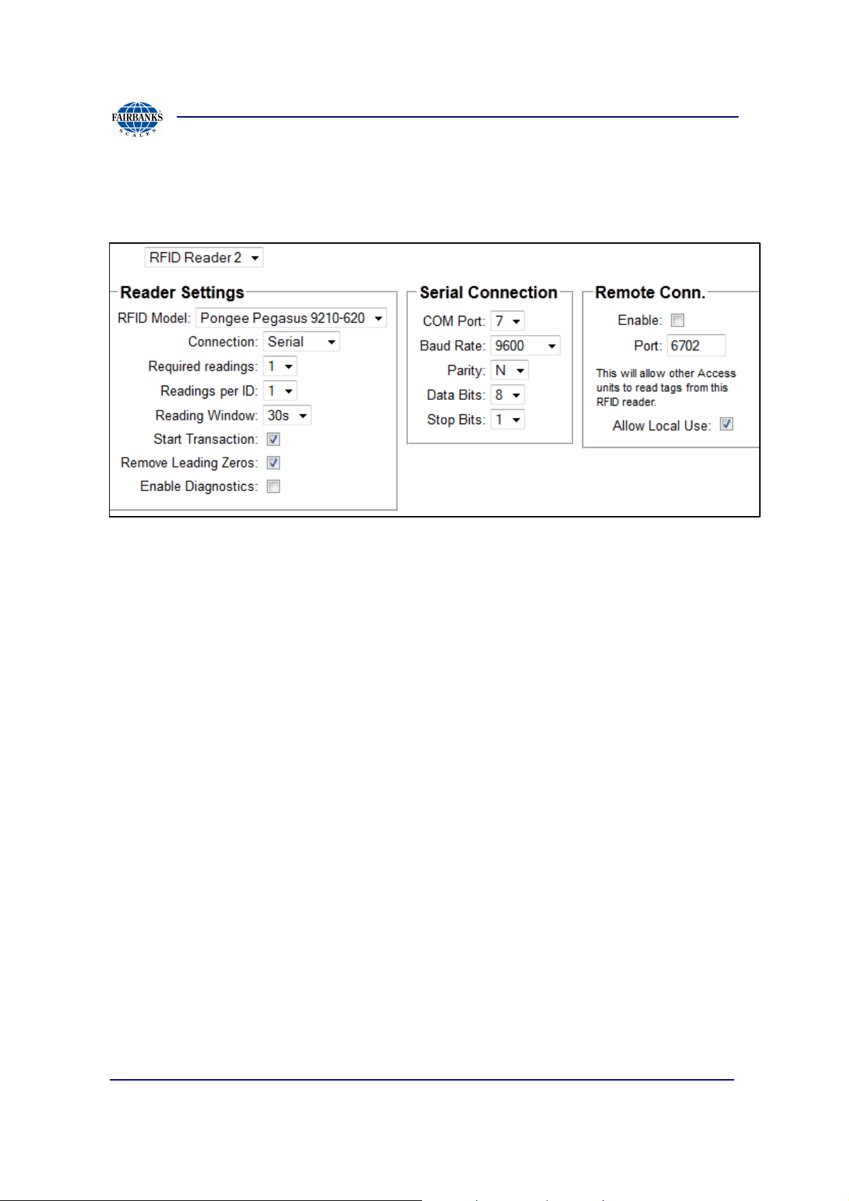
Section 3: Access Terminal Screens Defined
3.3.5. Rfid Reader Setup, Continued
RFID Model: Pongee Pegasus Readers
Pongee Pegasus Readers: The Pegasus reader sends card numbers continuously
and there are often a number of erroneous readings. The following settings will allow
the terminal to filter out the actual card number that is being detected
Required Readings: Make the reader send a number of readings before looking for
a card number. This should be in the range of 6-9.
Readings Per ID: Set the number of readings of an ID that must be with in the
required number of readings before that ID would be considered valid. For example,
if the previous setting is 6 and this setting is 3, then there will be a total of 6 readings.
For an ID to be considered value, there must be 3 readings of that ID out of the 6
readings available.
Reading Window: Since the readings are continuously coming in a reading window
is required. This prevent a duplicate erroneous reading from being considered a card
when the readings come in every so often. The default value is 30 seconds.
01/13 94 51299 Rev. 1
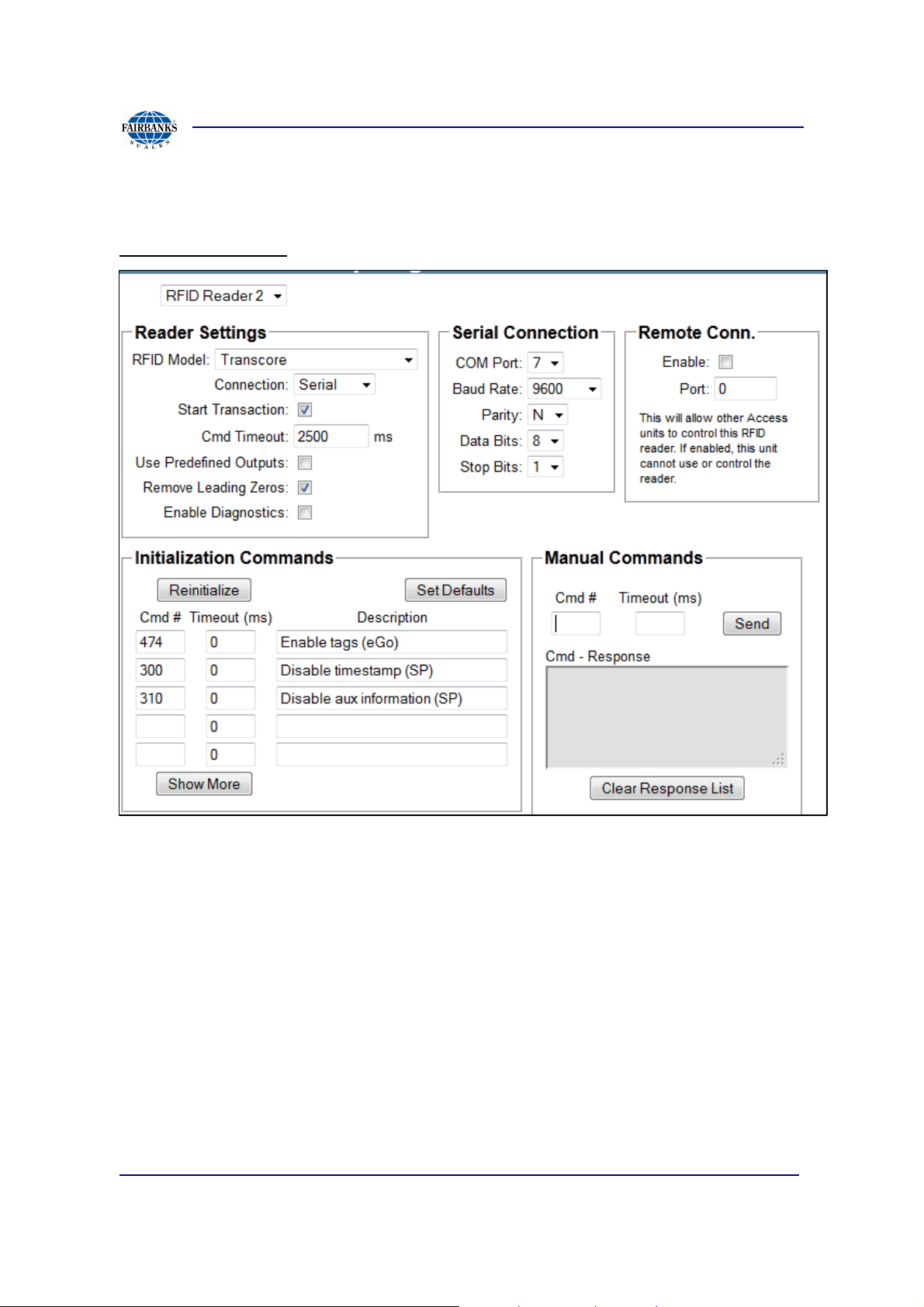
Section 3: Access Terminal Screens Defined
3.3.5. Rfid Reader Setup, Continued
TransCore Readers
Command Timeout: Enter a command timeout in milliseconds. Default is 2500 ms.
Use Predefined Outputs: There are two options for using the outputs on the
Transcore reader.
1.) Use the predefined behavior of the outputs (turning this option on). In this
case the reader will control the outputs and the Access terminal will only be
able to monitor the outputs.
2.) Direct control of the outputs by the terminal (turning this option off). In this
case the Access terminal will be able to control the outputs. This does require
configuring a remote IO source on the Input/Output Setup page. Just select
TransCore IO and select the reader slot the the TransCore reader is
configured in.
01/13 95 51299 Rev. 1

Section 3: Access Terminal Screens Defined
3.3.5. Rfid Reader Setup, Continued
Initialization Commands: To allow customization of the Transcore reader, various
commands can be sent to the reader to initialize it. The terminal will put the reader at
factory defaults. Then additional commands can be sent to modify its behavior as
necessary. Default commands are: 474 to read tags on the 2110 reader and 300,
310 to disable axillary information from the 1620 reader.
Reinitialize: Use this button to reinitialize the reader after making changes.
Show More/Less: Use this button to show more or show less initialization
commands.
Manual Commands: Use this area to send a command directly to the reader. Enter
the command number and a timeout value. If no timeout value is entered, the default
will be used. Refer to the Transcore reader's manual for details on commands to
send.
Command Response: This are will display the response from the reader for that
command.
Serial Connection
Serial COM Port: Select the serial port that the device is connected to.
Baud Rate: Select the baud rate for the serial communications with the device.
Parity: Select the parity setting for the serial communications: N - none, O - odd, E -
even, S - space, M - mark.
Data Bits: Number of data bits in the serial communications.
Stop Bits: Number of stop bits in the serial communications.
01/13 96 51299 Rev. 1

Section 3: Access Terminal Screens Defined
3.3.5. Rfid Reader Setup, Continued
Network Connection
Host: Enter the host name or the IP address of the device or the serial to Ethernet
converter that is connected serial to the device.
Port: Specify the TCP port number that the data is being sent from the host. See
documentation or configuration of the host for this information.
Configure Device: Click on this link to open the host in a web browser.
Remote Connection
Enable: If this terminal is not directly using the device but instead just acting as a
serial to Ethernet converter, then enable this option. In this case the other terminal
would use the IP address of this terminal as the host name and the port number
specified.
Port: Specify the TCP port on the terminal to provide device data on.
Allow Local Use: Enabling this will allow this terminal and another terminal to both
control the device. Normally if a remote connection is being use this terminal does
not use the RFID reader. This is only available for certain RFID readers.
01/13 97 51299 Rev. 1

Section 3: Access Terminal Screens Defined
A
I
H
G F E
D C b
A
b
3.3.6. Scale Indicator Setup
General Settings
• Scale Type: For all connections to a scale, use the Generic type.
• Connection: Select serial for direct connection from FBAS terminal to scale
indicator, Select Network for connecting to another unit or a device extending
scale data via TCP/IP communication. *Note the top central area changes
options from Serial Connection to Network Connection, the above shows the
more common Serial Connection.
o Serial Connection
COM PORT: Select the serial port that the device is connected
to. Available for scale RS232 serial data includes COM 4,3,2.
BAUD Rate: Select baud for the serial communication to device
Parity: N - none, O - odd, E - even, S - space, M - mark
Data Bits: Number of data bits in the serial communications.
01/13 98 51299 Rev. 1

Section 3: Access Terminal Screens Defined
C
D
3.3.6. Scale Indicator Setup, Continued
Stop Bits: Number of stop bits in the serial communications.
Time Out:
o Network Connection
Host: Enter the host name or the IP address of the device or the
serial to Ethernet converter that is connected serial to the device.
Port: Specify the TCP port number that the data is being sent
from the host.
Timeout:
Protocol: UDP or TCP/IP
• Required Readings: Specify the number of consecutive and identical
readings that must be read before the reading will be used. This setting can be
used to compensate for a scale indicator that does not provide motion status.
In that case a high value such as 6 or 9 should be used. The default value is
3.
• Buffer Size: Option allows lower buffer readings when capturing a trace
session for troubleshooting.
• Tracing Enabled: This value should be unchecked unless needed
temporarily for diagnostic purposes.
• Trace Interval: Set the interval at which the diagnostic scale data is reported.
A setting of zero maybe useful for showing every reading, but will cause very
high CPU loading. Verify after tracing is complete to disable the above tracing.
Remote Connection:
• Enable: If this terminal is not directly using the device but instead just acting
as a serial to Ethernet converter, then enable this option. In this case the other
terminal would use the IP address of this terminal as the host name and the
port number specified.
• Port: Specify the TCP port on the terminal to provide device data on.
Quick Setup:
• A number of default scale data formats are supported. Just click on the button
to setup the data and field formats, use as a guide and not a solution to scale
indicator setup readings.
01/13 99 51299 Rev. 1

Section 3: Access Terminal Screens Defined
E
F
3.3.6. Scale Indicator Setup, Continued
Data Format:
• Delimiters: If there is a common delimiter between each field within the
reading. This is typically one character and often a space character.
• Start: Specify a start character(s) that indicates the beginning of the reading.
Not all data formats have a start character, but when there is it is often the
ASCII start to text (STX) character (hexadecimal value of 0x02). You can
select common characters from a list or enter a custom value. To enter a
hexadecimal value prefix it with '0x'.
• Field: Up to 5 data fields can be configured within the reading. There are four
fields that were looking for the Weight, Units (of measure), the Mode, and
finally the Status. Often the unit of measure and mode are combined with the
status field. If there is an area of the reading that must be skipped use the
Mask field and specify the number of bytes (characters) to skip. For each field
you can optionally specify the the number of bytes in each field. This is not
necessary most of the time but can be useful. Each field that is specified has
its own data mappings as well. At a minimum there must be a weight field. In
general, if any of the four fields are available they should be configured here.
• End: Specify an end character(s) that indicates the end of the reading. All data
formats will have an end character. The most common is the ASCII carriage
return (CR) character (hexadecimal value of 0x0D). You can select common
characters from a list or enter a custom value. To enter a hexadecimal value
prefix it with '0x'
Weight Field Setup:
• The weight data is parsed based on digits and possibly a decimal point. The
only other information that is included (sometimes) in the weight field is an
indicator for positive and negative values.
• Positive Indicator: You can select common characters from a list or enter a
custom value. To enter a hexadecimal value prefix it with '0x'. The default
positive indicator for most data formats (if any) is a space.
• Negative Indicator: You can select common characters from a list or enter a
custom value. To enter a hexadecimal value prefix it with '0x'. The default
negative indicator for most data formats (if any) is a minus sign (dash).
01/13 100 51299 Rev. 1
 Loading...