

Page 1
Installation Manual
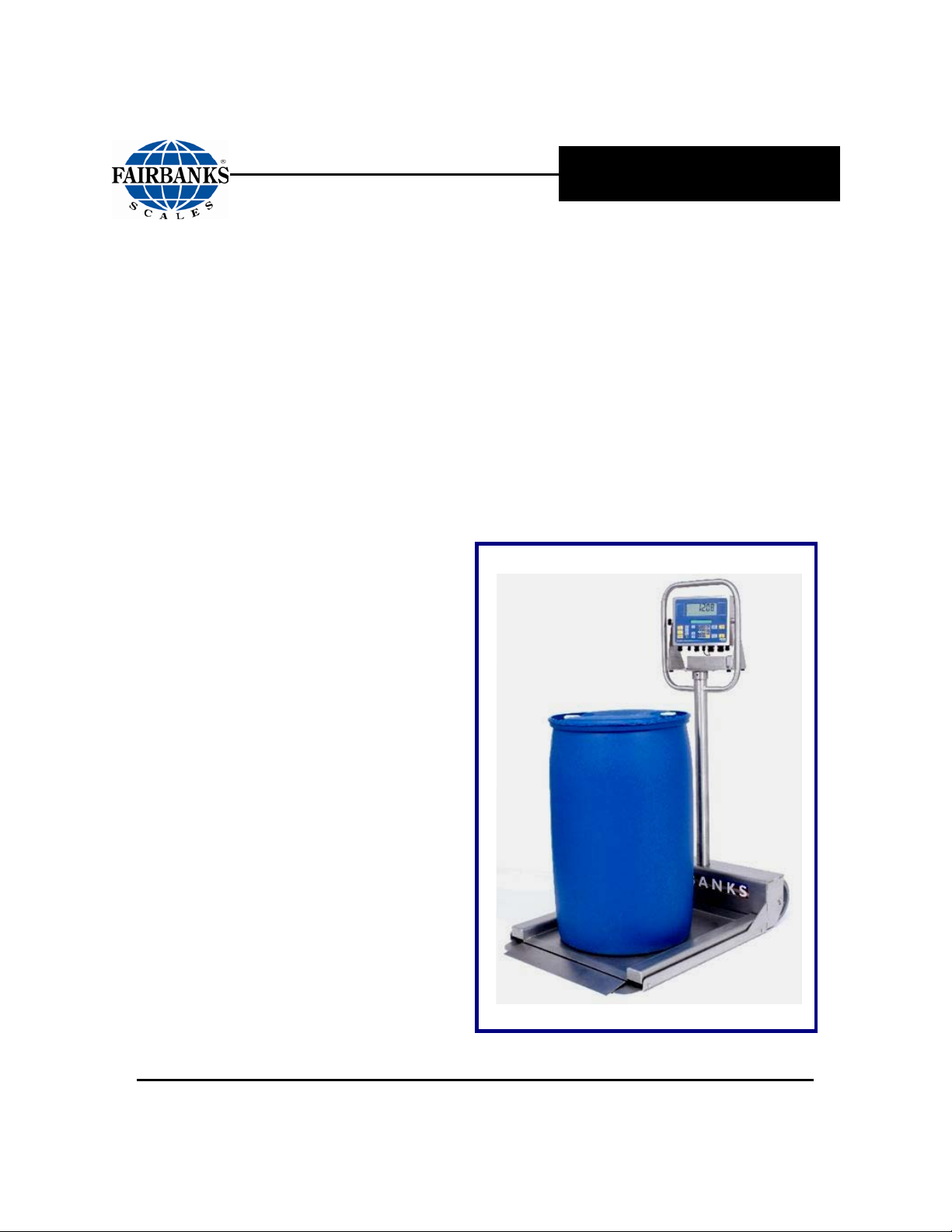
Fairbanks Transport Scale
© 2008-2010 by Fairbanks Scales, Inc. Revision 2 04/10
All rights reserved
51191
Page 2

Page 3

Amendment Record
AEGIS TRANSPORT SCALE
Document 51191
Manufactured by Fairbanks Scales Inc.
821 Locust
Kansas City, Missouri 64106
Created 8/08 Created
Revision 1 8/08 Documentation Release
Revision 2 04/10 Corrected part number and added load cell, feet and mounting bolts parts lists
and drawings.
04/10 3 51191 Rev. 2
Page 4

Disclaimer
Every effort has bee n made to provide com plete and accurate inform ation in this manual. However,
although this m anual may include a specificall y identified warranty notice for the pr oduct, Fairbanks
Scales makes no representations or warranties with respect to the contents of this manual, and
reserves the right to make changes to this manual without notice when and as improvements are
made.
Fairbanks Scales shal l not be liable f or any loss, damage, c ost of repairs, i ncidental or conseq uential
damages of any kind, whether or not based on express or implied warrant y, contract, negligence, or
strict liability arising in connection with the design, development, installation, or use of the scale.
© Copyright 2008-2010
This document contains proprietary information protected by copyright. All rights are reserved; no part
of this manual may be reproduced, copied, translated or transmitted in any form or by any means
without prior written permission of the manufacturer.
04/10 4 51191 Rev. 2
Page 5

Table of Contents
SECTION 1: GENERAL INFORMATION .................................................................. 7
1.1. Introduction ............................................................................................................. 7
1.1.1. Stainless Steel Transport Scale Features ........................................................................... 7
1.1.2. Applications.......................................................................................................................... 7
1.1.3. Specifications ....................................................................................................................... 8
1.2. Conferring with Our Client ..................................................................................... 9
1.2.1. Service Technician’s Responsibilities ................................................................................ 11
1.2.2. Users’ Responsibility ......................................................................................................... 11
SECTION 2: OPERATIONS .................................................................................... 12
2.1. Introduction ........................................................................................................... 12
2.1.1. Unpacking .......................................................................................................................... 12
2.1.2. Assembling the Pilla r ......................................................................................................... 13
2.1.3. Positioning the Equipment ................................................................................................. 14
2.1.4. Moving the Scale ............................................................................................................... 15
SECTION 3: SERVICE AND MAINTENANCE ........................................................ 16
3.1. Scale Assembly Maintenance .............................................................................. 16
3.1.1. Scale Assembly Troubleshooting ...................................................................................... 16
3.1.2. Platform Assembly Testing ................................................................................................ 16
3.2. General Troubleshooting ..................................................................................... 17
3.2.1. Disassembling the Platform ............................................................................................... 18
3.2.2. Pillar Replacement Steps .................................................................................................. 19
3.2.3. Load Cell Testing ............................................................................................................... 21
3.2.4. Load Cell Replacement ..................................................................................................... 21
3.2.5. Replacing the Scale Platform Wheels ............................................................................... 23
SECTION 4: PARTS ................................................................................................ 24
4.1. 24” x 30” Mild Steel Parts List (p/n 28877) .......................................................... 24
4.2. 24” x 30” Mild Steel Parts Diagram (p/n 28877) ................................................. 25
4.3. 24” x 30” Mild Steel Sub-Assembly (p/n 28792, 28793) ...................................... 26
4.4. 24” x 30” Stainless Steel Parts List (p/n 28881) .................................................. 27
4.5. 24” x 30” Stainless Steel Parts Diagram (p/n 28881) .......................................... 28
4.6. 24” x 30” Stainless Steel Sub-Assembly (p/n 28794, 28795) .............................. 29
04/10 5 51191 Rev. 2
Page 6

Page 7

Section 1: General Information
Chemical
Textile
Scrap or Recycling
Pharmaceutical
The Transport Scale accommodates
1.1. INTRODUCTION
The Transport Scale is a self-contained portable scale designed for weighing
drums in various locations throughout a plant or factory.
• It has an extremely low profile of one-and-a-half inch (1½”) for easy on− and
off−loading.
• Available in Mild Steel and Stainless Steel.
• Four capacities of 500, 1000, 2000 and 2500.
• The load cell cables connect inside the platform with a single, four (4)
conductor shielded cable.
• Load Cell Construction Ratings: Mild Steel Scales IP67, Stainless
Steel Scale IP69K (hermetically sealed).
• The Platform is supported from the Base
Weldment Assembly by four (4) 17-4 PH
Stainless Steel Shear Beam Load Cells
.
• A Bubble Level in the plat for m center hel ps t o
level the scale.
• The
Transport Scale accommodates a variety
of analog weight indicator models.
1.1.1. Stainless Steel Transport
Scale Features
The Fairbanks Stainless Steel Transport Scale
has following features.
• 304 Stainless Steel Constr uc ti on.
─ Continuous welds on the platform.
─ Brushed metal finish.
• Available with an Intrinsically Safe Controller.
1.1.2. Applications
• Manufacturing • Food & Beverage
•
•
•
•
a variety of Analog indicator models.
04/10 7 51191 Rev. 2
Page 8

Feature
Description
Platform Size
Scale Capacities
Endloading
Load Cell Excitation
Grounding
Interface
Platform Accuracy up to 0.02%
Hermetically Sealed Load Cells
1.1.3. Specifications
24” x 30”
500, 1000, 2000 and 2500 lbs.
100% of capacity all models except 2500 lb model which is rated at 80%.
5 to15 VDC
Less than 3 Ohms to True Earth Ground
Analog
Temperatures
Humidity
Accuracy
Operating: -10°C to 40°C (14°F to 104°F)
Storage: -20°C to 70°C (14°F to 158°F)
10 to 100%, Wash-down
Section 1: Gen er al Information
Power Cable
Instrument Cable
Platform Construction
Load Cell Construction
Approvals
Thirty cable feet (30’) of four (4) conductor interface cable; PVC jacketed.
7’ cable extends between the scale and indicator.
Type 304 Stainless Steel, br us hed.
17-4 Stainless Steel
Platform Approval:
• NTEP CC# 08-044.
• MC Approved
.
04/10 8 51191 Rev. 2
used on the
Stainless Steel models.
• Prevents problems with accidental spills and washdown.
Page 9

Section 1: Gen er al Information
Absolutely NO physical, electrical or program modifications other than
1.2. CONFERRING WITH OUR CLIENT
Prior to installation, always verify that the
equipment satisfies the customer's
requirements as supplied, and as
described in this manual.
If the equipment cannot satisfy the customer’s application, the Fairbanks
Transport Scale should not be delivered.
The technician must recommend the best arrangement for the Transport
Scale to provide the most accurate weighing position.
The warranty policy must be fully explained and reviewed with the
customer.
It is the customer/operator's responsibility to ensure the
equipment provided by Fairbanks Scales is operated within the
parameters of the equipme nt ' s spe cifications and protected from
accidental or malicious da m a ge .
WARNING!
selection of standard options and accessories can be made by
customers to this equipment
Repairs are performed by Fairbanks Scales Service Technicians and
Authorized Distributor Personnel ONLY!
Failure to comply with this policy voids all implied and/or written
warranties.
04/10 9 51191 Rev. 2
Page 10
Section 1: Gen er al Information
All Transport Scale Interface Cables used shall be located a
IMPORTANT INSTALLATION NOTICE
minimum of thirty-six (36”) inches distance away from all single
and multiple phase high energy circuits and electric curre nt
carrying conductors .
• Also included is the scale components themselves, such
as 120 volt AC, 240 volt AC, 480 volt AC and electric
supply of higher voltage wiring runs and stations, AC
power transformers, overhead or buried cables, electric
distribution panels, electric motors, florescent and high
intensity lighting which utilize ballast assemblies, electric
heating equipment, traffic light wiring and power, and
relay boxes.
• This includes all scale components, including digital
weight indicators and peripheral devices that are not
designed to operate on internal combustion engine driven
electric generators and other similar equipment.
Ele ct ric arc weld i n g can severely damage scale
components such as digital w eight indi c a t ors, junction boxes,
balance boards, secti ona l c ont rollers, power supplies, and load
cells.
For additional information, contact your Fairbanks Scales Representative.
04/10 10 51191 Rev. 2
Page 11

Section 1: Gen er al Information
1.2.1. Service Technician’s Responsibilities
All electronic and mechanical calibrations and/or adjustments required for making
this equipment perform to accuracy and operational specifications are considered
to be part of the installation.
─ They are included in the installation charge.
─ Only those charges which are incurred as a result of the equipment's inability to
be adjusted or calibrated to performance specifications may be charged to
warranty.
If the equipment consists of printed circuit assemblies, they must be handled
using ESD handling procedures, and must be replaced as units.
─ Replacement of individual components is not permitted.
─ The assemblies must be properly packaged in ESD protective material and
returned intact for replacement credit per normal procedures.
All electrical assemblies must be replaced as assemblies or units.
─ Replacement of individual components is not permitted.
─ These components must be returned intact for replacement credit using the
standard procedures.
All electronic and mechanical adjustments are considered to be part of the
installation, and are included in the installation charge(s).
─ Included is any required computer programming or upgrades.
─ Included are any accuracy and/or operational specificatio n changes.
Only those charges which are incurred as a result of the equipment's
inability to be adjusted to performance specifications may be charged to
warranty.
The AC receptacle/outlet shall be located near the Indicator and easily accessible.
Electrical connections other than those specified may not be performed.
No physical alterations (mounting holes, etc.) are permitted during installation.
1.2.2. Users’ Responsibility
Absolutely no physic al, e lectrical or
program modifications other than
selection of standard opt ions and
accessories are to be made to this
equipment.
04/10 11 51191 Rev. 2
Page 12

Section 2: Operations
2.1. INTRODUCTION
The installing technici a n is res pons ible that all personnel are fully
trained and familiar wit h the equipment's capabilities and
limitations before the installation is considered complete.
The Fairbanks Transport Scale Platform arrives at the user’s site partially
assembled.
The Instrument Pillar must be inserted into the Platform Base, and then fastened.
2.1.1. Unpacking
Follow these guidelines when unpacking all equipment.
• Check in all components and accessories according to the customer's order.
• Remove all components from their packing material, checking against the
invoice that they are accounted for and not damaged.
─ Advise the shipper immediately, if damage has occurred.
─ Order any parts necessary to replace those which have been damaged.
─ Keep the shipping container and packing material for future use.
─ Check the packing list.
• Collect all necessary installation manuals for the equipment and
accessories.
• Open the Indicator box(es), then follow exactly all the accompanying instructions
in the Installation Manual.
The Transport Scale is shipped in a wooden
crate on top of a pallet.
1. Remove the crate lid.
2. Locate the side closest to the wheels,
positioning it like a ramp in the
illustration.
3. Install the pillar to the base asse mbly.
4. Wheel the Scale off of the shipping
crate.
04/10 12 51191 Rev. 2
Page 13

Section 2: User Operations
−
2.1.2. Assembling the Pillar
5. At the Wheel-base side of the
Platform, remove the four (4)
Fastening Bolts of the Cover using
the seven-sixteenths inch
(7/16”) Open-ended Wrench.
6. Pull out and unwrap the cables, set
the instructional CD aside, then open
the bag of assembly hardw ar e.
7. Using the pre-assembled Pull-string, carefully draw the Indicator Cable up
through the Pillar, and then out through the top Access Hole.
Allow extra slack on the cable.
8. Insert the Pillar into its collar on the Base.
9. Pull the cable firmly at the top to remove the slack.
10. Install the rubber boot over the load cell
cable and into the cable exit hole.
11. Use two Open-ended Wrenches.
A 9/16” on the 3/8” x 3-1/2” Bolts
through the Pillar and on the
Fastening Nuts.
12. Tighten the (2) ¼” x .50” Bolts using a
7/16” Open-ended Wriench to
secure the pillar to the base.
13. Wrap up excess Load Cell Cable and
secure in the compartment at the base
of the pillar.
14. Reinstall the Cover on the Platform with
the six (6) Fastening Bolts.
15. Wire the cable to the Indicator.
04/10 13 51191 Rev. 2
Page 14

2.1.3. Positioning the Equipment
Position the equipment with the following points in mind.
• Rest the Platform on a smooth
surface, within 1/8”, and on a level
plane, within ¼” across both the
length and width of the platform .
• The four corners of the Platfor m must
rest solidly on the surface, and not
rock. Unlevel flooring and foreign
material under the Platform can cause
an “out-of-level” condition, and the
weight readings could be incorrect.
• Platform vibrations may also affect the
weighing accuracy. Wherever
possible, locate the platform as far
away from heavy, low frequency
vibrations as much as poss i ble.
Section 2: User Operations
• Do not load the platform if there is any
evidence of damage to the platform or
supporting structure.
• Ease of access is very important.
Allow plenty of room for maneuvering
a loaded dolly.
• Reading the Indicator is also important to workers, so place it in a very visible
position.
• The scale is to be placed on a flat, solid, level surface, one that fully supports the
weight of the platform plus a full capacity load.
• Whenever moving the scale to another location, it is important to lo cate the
Scale on a level area using the Bubble Level in the center of the Platform
for accurate and consistent weighing.
04/10 14 51191 Rev. 2
Page 15

Section 2: User Operations
2.1.4. Moving the Scale
1. Remove all objects from the Platform.
2. Remove the AC Power from the Instrument, if applicable.
3. From the back of the scale, hold firmly onto the Handle Bars, place one foo t on
the platform base, then pull down on the Handle Bars until the unit rides only on
the wheels.
4. Transport the scale to its new location.
5. CAREFULLY lower the scale down to the floor.
6. Check the Bubble Level to confirm the scale is level.
7. Reapply AC Power to the Instrument, if applicable.
The Scale is again ready for weighing.
04/10 15 51191 Rev. 2
Page 16

Section 3: Service and Maintenance
3.1. SCALE ASSEMBLY MAINTENANCE
Follow these point s to k eep the Tr ansport Scale well maintained.
• Clear all debris from between the spaces of the platform
sides, ramps, edges, and the surface beneath the platform.
• At the end of each day, wipe all surfaces with antibacterial
cleaner.
• Once a month, shine the Stainless Steel with only high
quality polish.
• Clean the wheels with a strong cleaner, then when
necessary, oil them only with
Motor Oil
.
White Grease or 30 Wt.
─ Spray lubricants are not recommended.
3.1.1. Scale Assembly Troubleshooting
Except for severe structural damages, most Platform Assembly problems can be
traced to the following causes:
• Material under or around the Platform.
• Improperly seated Load Cell Feet.
• Faulty Load Cells.
• Loose or damaged components.
3.1.2. Platform Assembly Testing
1. ZERO the Instrument Display .
2. Apply a test load of 25% of the Scale’s capacity to one corner.
─ The Instrument should display a weight reading within 0.1% o f the a ppl ied
weight, or One Instrument Division, whichever is greater.
3. Repeat Step 3 for all the corners, placi ng the s ame Test Lo ad on each corner.
04/10 16 51191 Rev. 2
Page 17

Section 3: Service & Ma intenance
3.2. GENERAL TROUBLESHOOTING
From the following chart, identify the symptom(s) and cause(s) of each malfunction,
solving each issue with an appropriate solution.
SYMPTOM CAUSE SOLUTION
Display Stays at Zero
Erratic Weights
Inaccurate Weights
1. Load Cell connections faulty.
2. Instrument faulty.
3. Damaged Interface Cables.
─ Foreign object around load cells,
ramps, or under platform.
─ Excessive vibrat ion near platf orm.
─ Instrument faulty.
─ Platform not level within ¼” (3.0°).
─ Surface not smooth within 1/8”.
─ Faulty/bad Load Cell.
1. Instrument out of span.
2. Instrument not properly adjusted to
zero.
3. Faulty/bad Load Cell.
1. Cable replacement.
2. Service Instrument.
3. Test and replace according to
Subsection
1. Clear the area.
2. Remove the vibration source.
3. Service Instrument.
4. Level the platform surf ace.
5. Smooth the platform surface.
6. Test and replace according to
Subsection
1. Check and alter per the
Instrument Service Manual.
2. Zero the instrument according
to normal operation
procedures.
3. Test and replace according to
Subsection
3.2.3. and 3.2.4.
3.2.3. and 3.2.4.
3.2.3. and 3.2.4.
04/10 17 51191 Rev. 2
Page 18

Section 3: Service & Ma intenance
CAUTION
3.2.1. Disassembling the Platform
1. Cycle-down the power to the indicator, then unplug the unit, if applicable.
ALWAYS remove power from the Instrument before servicing.
2. Lay down the Scale on its back.
3. At the Wheel-base End of the Platform,
remove the four (4) Fastening Bolts of
the Cover using the seven-sixteenths
(7/16”) Open-ended Wrench.
inch
4. Using a half inch (½”) Open-ended
Wrench
each corner of the Platform until each is
past the Load Cell Rubber Foot.
5. Carefully pull up, then out the top edge of
the Scale Platform, and lay it down on the
Pillar.
Be careful not to pinch fingers.
─ Doing this will expose where the Cables
meet at the base of the Indicator Pillar,
and also the Load Cell Connections in
each corner.
6. Check the Interface Cable from the
Platform to the Instrument for visible
breaks or cracks.
, unscrew the four (4) Bolts on
─ While laying down the Platform, pull
out some slack of the wires from the
hole to the Pillar.
04/10 18 51191 Rev. 2
Page 19

3.2.2. Pillar Replacement Steps
1. Unplug/remove the cable to the Indicator
(or Battery Pack Unit) from the Scale
Platform connection.
2. If it is present, remove the fastening
screws on the battery pack, pulling it
away and setting it aside.
Section 3: Service & Ma intenance
3. Remove all the fastening bolts on the
Indicator Stand, pulling the Indic at or
away and setting it aside.
4. At the Wheel-base side of the Platform, remove the
four (4) Fastening Bolts of the Cover using the
seven-sixteenths inch (7/16”) Open-ended
Wrench.
5. Once opened, check the Interface Cable from the
Platform to the Indicator for visible breaks or cracks.
6. Replace the cable, if needed.
04/10 19 51191 Rev. 2
Page 20

−
3.2.2. Pillar Replacement Steps,
Section 3: Service & Ma intenance
Continued
7. Use two 9/16” Open-ended Wrenches
on the 3/8” x 3-1/2” Bolts through the Pillar
and on the Fastening Nuts.
8. Remove the (2) ¼” x .50” Bolts using a
7/16” Open-ended Wrench to loosen the
pillar from the base.
9. Carefully push the Indicator Cable through the
top Access Hole, pulling the old Pillar away
from the base carefully, tugging the cable
gently if it hangs up so not to damage it.
10. Carefully push the Indicator Cable up through
the new Pillar, and then out through the top
Access Hole.
Allow extra slack on the cable.
11. Insert the new Pillar into its hole on the Base, pulling the cable firmly at the top to
remove the slack.
12. Fasten the new Pillar Unit to the Base with the Nuts and Bolts.
13. Rewire the cable to the Indicator.
04/10 20 51191 Rev. 2
Page 21

Section 3: Service & Ma intenance
nearest position to
3.2.3. Load Cell Testing
When corners do not match the correct tolerances, disconnect/cut each Load Cell
Cable at the Wheel Base Access Area, then test each Load Cell for the settings on
the following chart.
TEST READING REMARKS
Green to Black (Input) 1106 Ohms (+5 / -2 Ohms) Input Resistance
Red to White (Output) 1000 Ohms (+5 / -2 Ohms) Output / Bridge Resistance
Yellow (Shield) to Load Cell Case
Input and Output Leads to Shield
Input and Output Leads to Case
More than 1,000 megohms Insulation Resistance
3.2.4. Load Cell Replacement
NOTE:
A Torque Wrench of up to 90 ft/lbs must be used when replacing the Load
Cells.
1. Remove the two bolts securing each Load Cell to its
mounting block.
2. Pull away the Load Cell from the Platform.
3. Follow the Interface Cable down through Pillar Access Hole
to the Side Rails to either the Junction Box (for Stainless
Steel Models), or the Summing Area (for Mild Steel
Models).
─ Pull the cable back and forth to be certain it is the correct
one.
─ Make a note of the cable routing
design and the wiring
connections.
Load Cells are in the
the Access Hole.
04/10 21 51191 Rev. 2
Page 22

Section 3: Service & Ma intenance
Be very careful to select the correct Load
The Junction Box attaches with Velcro®.
3.2.4. Load Cell Replacement, Continued
4a. For a Stainle ss St eel S cal e, r e mov e t he si x (6) Phillips-head screws securing
the Junction Box Cover.
4b. Open the Junction Box Cover, identifying the correct cable.
5. Cut the five (5) Load Cell Cable bundled
connections inside the Junction Box.
6a. If the Load Cell being replaced is in the
farthest position, tie a drag string
to the cable, securing it with tape.
─ The cable for the nearest position
Load Cells can be accessed and
pulled through much easier .
6b. Carefully pull the Load Cell Cable out
through the access hole, down the
Side Rail, tugging gently so the
string will stay fastened to it.
7. Carefully remove the replacement Load
Cell from its packing, inspecting it
thoroughly for any obvious shipping or
handling damages.
8. For Load Cell being replaced is in the
farthest position, tie the drag string
to the new cable, securing it with
tape.
9. Pull the new Cable back trough the
Scale Platform, through the Pillar Access
Hole, and then into the Junction Box (if
Stainless Steel Scale), using the
identical path as the old cable.
10. Place the replacement Load Cell onto its
Mounting Block, then secure it with the
two (2) Mounting Bolts.
Cell Cable before cutting and replacing it.
11. Assemble foot to the new load cell,
tightening foot fully .
12. Torque each Mounting Bolt to 90 ft/lbs.
04/10 22 51191 Rev. 2
Page 23

Section 3: Service & Ma intenance
WIRE COLOR
3.2.4. Load Cell Replacement, Continued
13. Strip away all the insulation from the four (4) Load Cell to a minimum of ¾”.
14. Using Crimp Connector s , fasten all five
(5) green wires together, all five (5) black
wires together, all five (5) white wires
together, all five (5) red wires together, and all
five (5) yellow wires together.
15. Replace the Junction Box Cover (for Stainless
Red
White (+) Signal
Black
Green (+) Excitation
Yellow Ground
Steel Scales), then the Platform Back Cover.
16. Place scale upright and find a level location to calibrate the scale.
─ If the scale rocks in the frame, adjust one of the front load cell feet to correct it.
17. Reapply power to the Instrument.
(−) Signal
(−) Excitation
18. Recalibrate the scale with the Instrument Service Manual.
19. Test the Platform for proper operations.
3.2.5. Replacing the Scale Platform Wheels
NOTE: It is not necessary to remove the End Cover for servicing a defective
Wheel, but it may be easier.
1. Using two (2) three-quarter inch (¾”) Open-ended Wrenches, remove
the Nut from the Axle Bolt, then discard the defective Wheel.
2. Replace the Wheel.
3. Screw the Axle Bolt to the Nut.
4. Place the Scale upright, then put it where it
best suits the user needs.
─ If the scale rocks in the frame, adjust one of
the front load cell feet to correct it.
.
04/10 23 51191 Rev. 2
Page 24

Section 4: Parts
4.1. 24” X 30” MILD STEEL PARTS LIST (P/N 28877)
04/10 24 51191 Rev. 2
Page 25

4.2. 24” X 30” MILD STEEL PARTS DIAGRAM (P/N 28877)
Section 4: Parts
04/10 25 51191 Rev. 2
Page 26

Section 4: Parts
4.3. 24” X 30” MILD STEEL SUB-ASSEMBLY (P/N 28792, 28793)
04/10 26 51191 Rev. 2
Page 27

4.4. 24” X 30” STAINLESS STEEL PARTS LIST (P/N 28881)
Section 4: Parts
04/10 27 51191 Rev. 2
Page 28

Section 4: Parts
4.5. 24” X 30” STAINLE SS STEEL PARTS DIAGRAM (P/N 28881)
04/10 28 51191 Rev. 2
Page 29

Section 4: Parts
4.6. 24” X 30” STAINLESS STEEL SUB-ASSEMBLY (P/N 28794, 28795)
04/10 29 51191 Rev. 2
Page 30

Page 31

Page 32

Manufactured by Fairbanks Scales, Inc.
Fairbanks Trans po r t Sc al e
821 Locust
Kansas City, MO 64106
www.fairbanks.com
INSTALLATION MANUAL
DOCUMENT 51191
 Loading...