

Fairbanks Aegis Drum Scales User Manual
Installation Manual
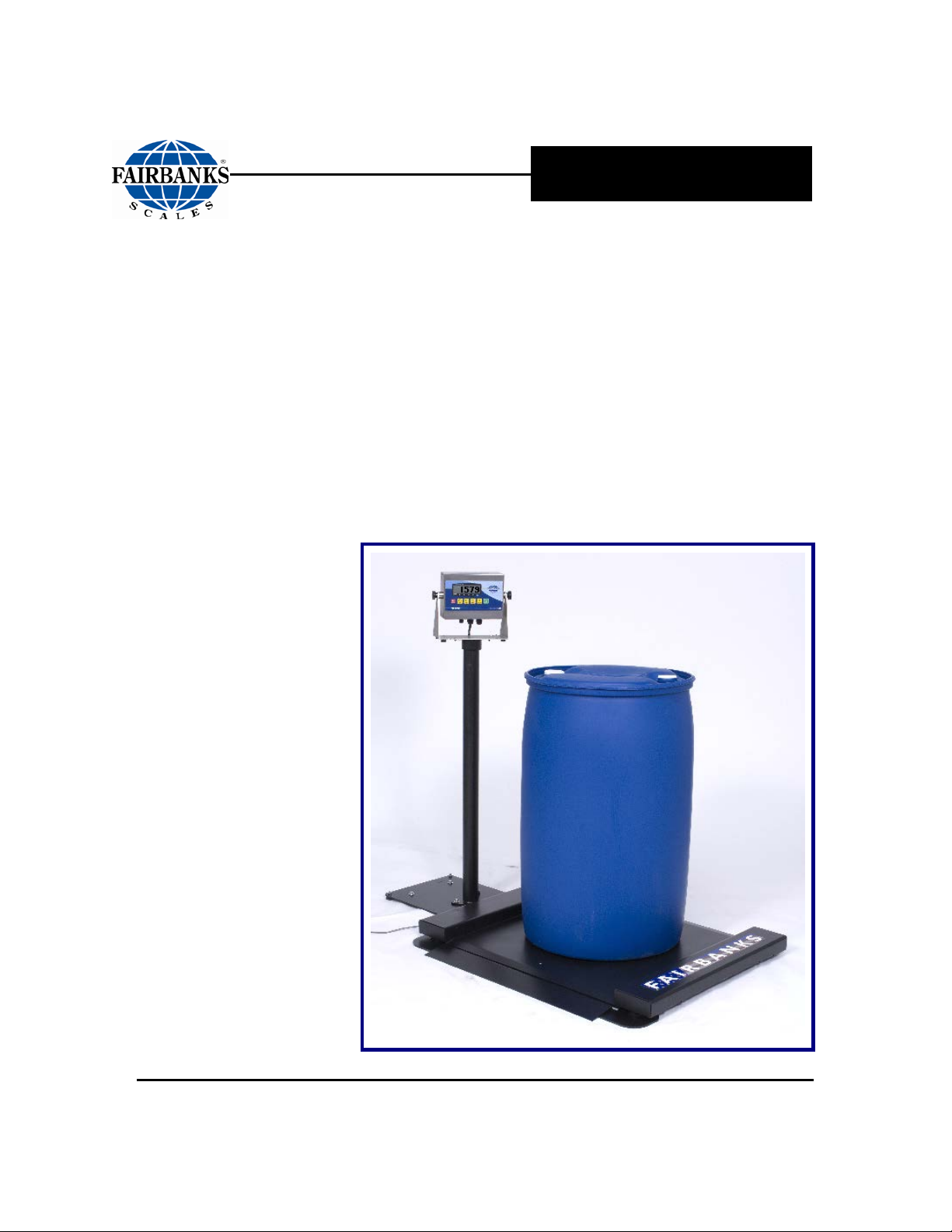
Aegis Drum Scale
© 2008-2010 by Fairbanks Scales, Inc. Revision 2 04/10
All rights reserved
51190

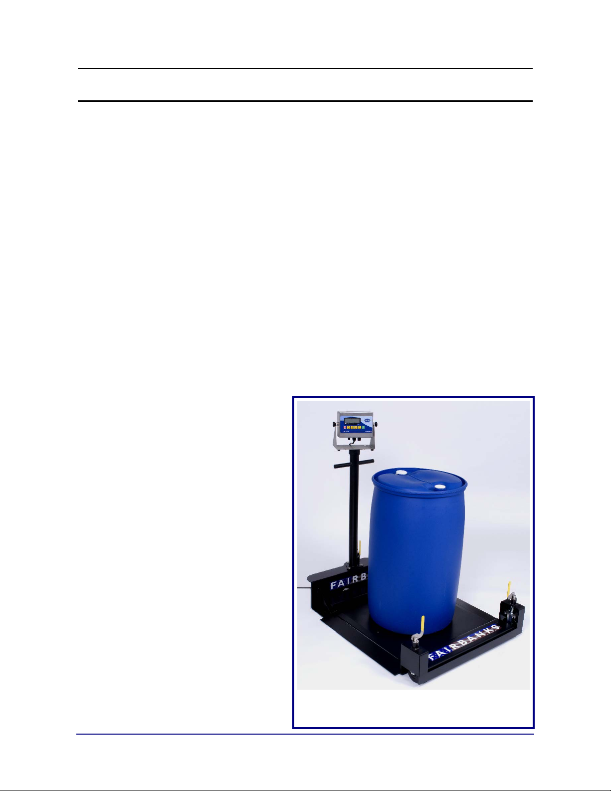
Aegis Stainless Steel Drum Scale, shown
Amendment Record
AEGIS DRUM SCALE
Document 51190
Manufactured by Fairbanks Scales Inc.
821 Locust
Kansas City, Missouri 64106
Created 07/08 Created Document
Revision 1 07/08 Preliminary Release
Revision 2 04/10 Corrected part number on page 29.
04/10 3 51190 Rev. 2
with optional Ramp and Integral Pillar

Disclaimer
Every effort has bee n made to provide com plete and accurate inform ation in this manual. However,
although this manual m ay include a specifically identi fied warranty notice for the product, Fairbanks
Scales makes no representations or warranties with respect to the contents of this manual, and
reserves the right to make changes to this manual without notice when and as improvements are
made.
Fairbanks Scales shal l not be liable f or any loss, damage, c ost of repairs, i ncidental or conseq uential
damages of any kind, whether or not based on express or implied warrant y, contract, negligence, or
strict liability arising in connection with the design, development, installation, or use of the scale.
© Copyright 2008-2010
This document contains proprietary information protected by copyright. All rights are reserved; no part
of this manual may be reproduced, copied, translated or transmitted in any form or by any means
without prior written permission of the manufacturer.
04/10 4 51190 Rev. 2

Table of Contents
TABLE OF CONTENTS ............................................................................................. 5
SECTION 1: GENERAL INFORMATION .................................................................. 7
1.1. Introduction ................................................................................................................ 7
1.1.1. Specifications ....................................................................................................................... 7
1.1.2. Applications.......................................................................................................................... 8
1.1.3. Accessories.......................................................................................................................... 8
1.2. General Service Policy ............................................................................................... 9
1.3. Conferring with Our Client ........................................................................................ 10
1.3.1. Service technician’ s Responsibilies .................................................................................. 10
1.3.2. Users’ Responsibility ......................................................................................................... 10
SECTION 2: SCALE INSTALLATION ...................................................................... 11
2.1. Overview .................................................................................................................. 11
2.1.1. Physical Installation Notes ................................................................................................. 11
2.1.2. Pre-Installation Checklist ................................................................................................... 12
2.1.3. Unpacking .......................................................................................................................... 12
2.1.4. Positioning the Equipment ................................................................................................. 13
2.2. Installation Steps...................................................................................................... 14
2.2.1. Assembling the Scale Platform ...................................................................................... 14
2.2.2. Wheel Kit Assembly Steps ................................................................................................. 15
2.2.2. Wheel Kit Assembly Steps, Continued .............................................................................. 16
2.2.3. Installing the Ramp(s) ........................................................................................................ 17
2.2.4. Installing Ramp(s) With Integral Pillar ............................................................................... 17
SECTION 3: USER OPERATIONS .......................................................................... 18
3.1. Moving the Scale with a Wheel Kit .......................................................................... 18
3.2. Changing Position of Top Plate ............................................................................... 18
SECTION 4: SERVICE & MAINTENANCE .............................................................. 19
4.1. General Troubleshooting .......................................................................................... 19
4.2. Scale Platform Troubleshooting ............................................................................... 20
4.2.1. Scale Platform Testing ....................................................................................................... 20
4.2.2. Load Cell Testing ............................................................................................................... 20
4.2.3. Load Cell Replacement Steps ........................................................................................... 21
4.2.3. Load Cell Replacement Steps, Continued ......................................................................... 22
SECTION 5: PARTS ................................................................................................. 24
5.1. 30 x 30 Mild Steel Parts List (p/n 28374) .................................................................. 24
5.2. 30 x 30 Mild Steel Parts Diagram (p/n 28374) ......................................................... 25
5.3. 30 x 30 Stainless Steel Parts List (p/n 28379) ......................................................... 26
5.4. 30 x 30 Parts Diagram (p/n 28379) ......................................................................... 27
5.5. 38 x 38 Mild Steel Parts List (p/n 28723) ................................................................. 28
5.6. 38 x 38 Mild Steel Parts DIAGRAM (p/n 28723) ...................................................... 29
5.6. 38 x 38 Mild Steel Parts Diagram (p/n 28723) .......................................................... 30
5.7. 38 x 38 Stainless Steel Parts List (p/n 28726) ......................................................... 31
5.9. Accessory Part Numbers ......................................................................................... 32
04/10 5 51190 Rev. 2

Section 1: General Information
Accuracy
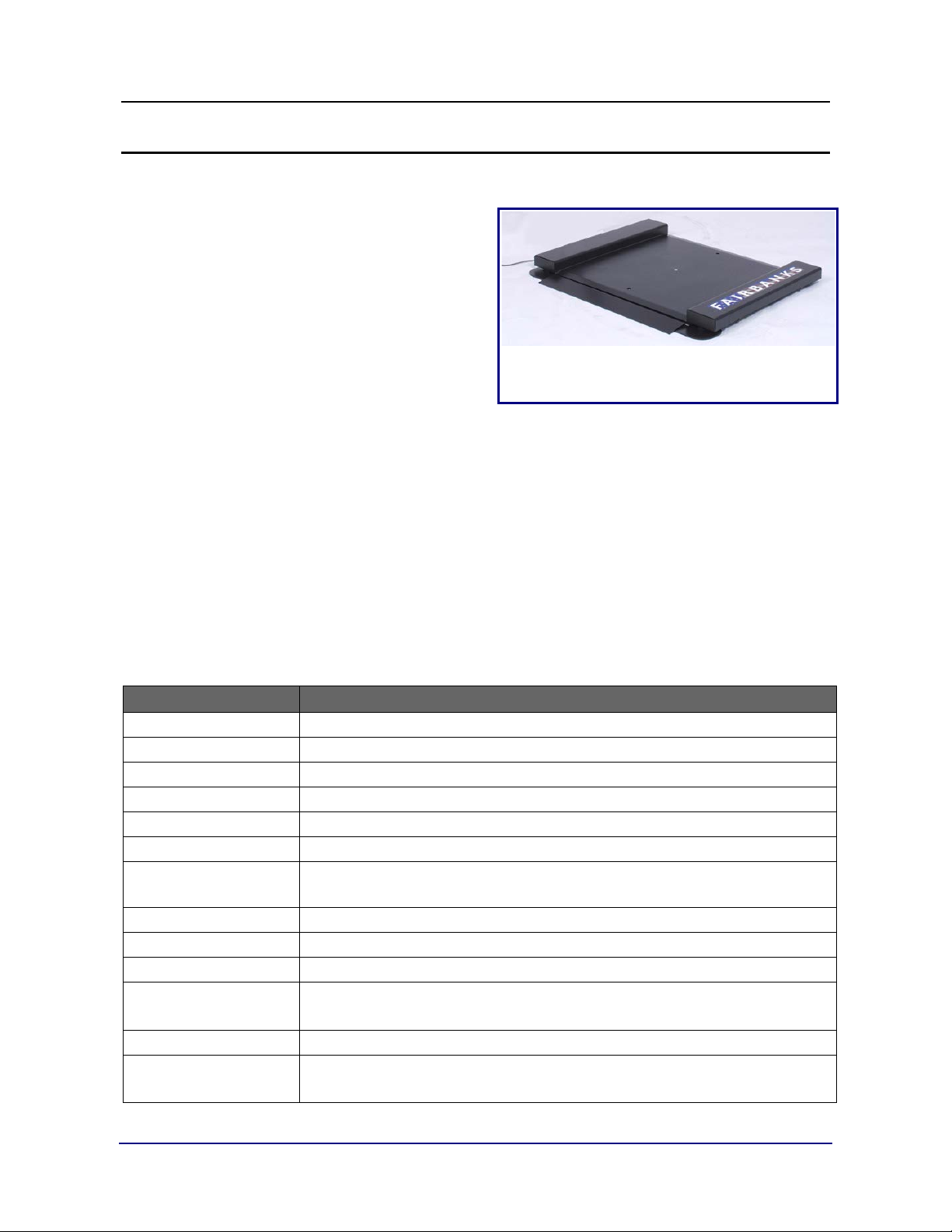
Ultra-low profile for easy on- and off-loading.
1.1. INTRODUCTION
The Aegis Drum Scale has a one-anda-half inch (1½”) low profile for easy onand off-loading.
• Threaded half-inch (½”) holes for
inserting Eyebolts, to make the Platform
easy to move.
• Available in Mild Steel and Stainless
Steel.
• Stainless Steel Load Cells are used on all models.
─ However on the Stainless Steel Platform Models, the Lo ad Cell s have a
“true” hermetically sealed (IP69K) rating (optional on Mild Steel Models).
• The Aegis Drum Scale is used with either analog or digital weight indicators.
• Three inch (3”) high Side Rails for pallet weighing.
• The Platform is supported by four (4) 17-4ph Stainless Steel Shear Beam Load
Cells.
• Bubble Level for platform leveling confirmation.
− Shown with optional Ramp.
1.1.1. Specifications
Feature Description
Platform Sizes
Overall Dimensions
Scale Capacities
Endloading
Load Cell Excitation
Instrument Signal
Temperatures
Humidity 10 to 100%, Wash-down (Stainless Steel models only)
Power Cable
Adjustment Limits
Construction
Approvals
30” x 30” x 1-½” and 38” x 38” x 1-½”
41” x 30” x 3” and 49” x 38” x 3”
500, 1000, 2000 and 2500 l bs .
100% of capacity all models except 2,500 lb model which is rated at 80%.
5 to15 VDC
Analog or Digital
Operating: -10°C to 40°C (14°F to 104°F)
Storage: -20°C to 70°C (14°F to 158°F)
Platform Accuracy up to 0.02%
Thirty cable feet (30’) of four (4) conductor interface cable; PVC jacketed.
• Scale must be level within three degrees (3°).
• Height adjustment allows for up to one-quarter inch (¼”) per foot.
Mild steel with black enamel finish; Type 304 PH stainless steel, brushed.
Both Stainless Steel and Mild Steel have
NTEP and CWM approvals PENDING.
FM Approved Load Cells.
04/10 7 51190 Rev. 2
Section 1: Genera l Information
−
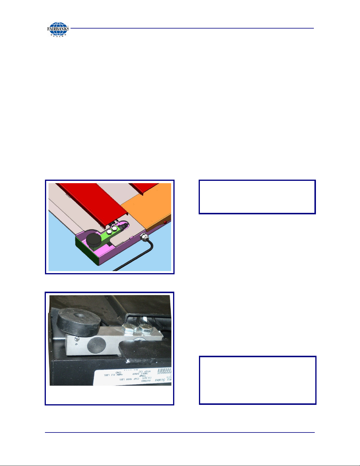
SHOCKLOAD
Example of Load Cell from a Mild Steel Scale
1.1.2. Applications
─ Manufacturing ─ Food & Beverage
─ Chemical ─ Textile
─ Scrap or Recycling ─ Pharmaceutical
1.1.3. Accessories
Available modifications and accessories include the following:
─ Loading Ramp ─ Stand-alone Pillar
─ Ramp with Pillar ─ Intrinsically Safe Controller
─ Wheel Kit ─ Quad-multiplexer Board
─ Factory Calibration and Quick Disconnect (not available for Intrinsically Safe Instrument)
DO NOT
THE SCALE!
.
04/10 8 51190 Rev. 2
“True” Hermetically Sealed Load
Cells
used on both the Stainless and
Mild Steel
Prevents problems with accidental
models.
spills and washdown.
Section 1: Genera l Information
Absolutely NO physical, electrical or program modifications other than
warranties.
WARNING!
1.2. GENERAL SERVICE POLICY
Prior to installation, always verify
that the equipment satisfies the
customer's requirements as
supplied, and as described in this
manual.
If the equipment cannot satisfy
the application and the
application cannot be modified to
meet the design parameters of the
equipment, the installati on
should NOT be attempted.
It is the customer/operator's responsibility to ensure the
equipment provided by Fairbanks is operated within the parameters
of the equipment's speci fi c a ti ons and pr ot ec t e d fr om ac c idental or
malicious damage.
selection of standard options and accessories can be made by
customers to this equipment
Repairs are performed by Fairbanks Scales Service Technicians and
Authorized Distributor Personnel ONLY!
Failure to comply with this policy voids all implied and/or written
04/10 9 51190 Rev. 2

Section 1: Genera l Information
1.3. CONFERRING WITH OUR CLIENT
• The technician must be prepared to recommend the arrangement of components
which provide the most efficient layout, using the equipment to the best possible
advantage.
• The warranty policy must be explained and reviewed with the customer.
• Refer to Instrument Manual for power requirements.
1.3.1. Service technician’ s Responsibilies
All electronic and mechanical calibrations and/or adjustments required for making
this equipment perform to accuracy and operational specifications are considered
to be part of the installation.
─ They are included in the installation charge.
─ Only those charges which are incurred as a result of the equipment's inability
to be adjusted or calibrated to performance specifications may be charged to
warranty.
If the equipm ent consists of printed circuit assemblies, they must be handled
using ESD handling procedures, and must be replaced as units.
─ Replacement of individual components is not permitted.
─ The assemblies must be properly packaged in ESD protective material and
returned intact for replacement credit per normal procedures.
1.3.2. Users’
Responsibility
Absolutely no physical, electrical
or program modifications other
than selection of standard
options and accessories are to
be made to this equipment.
04/10 10 51190 Rev. 2
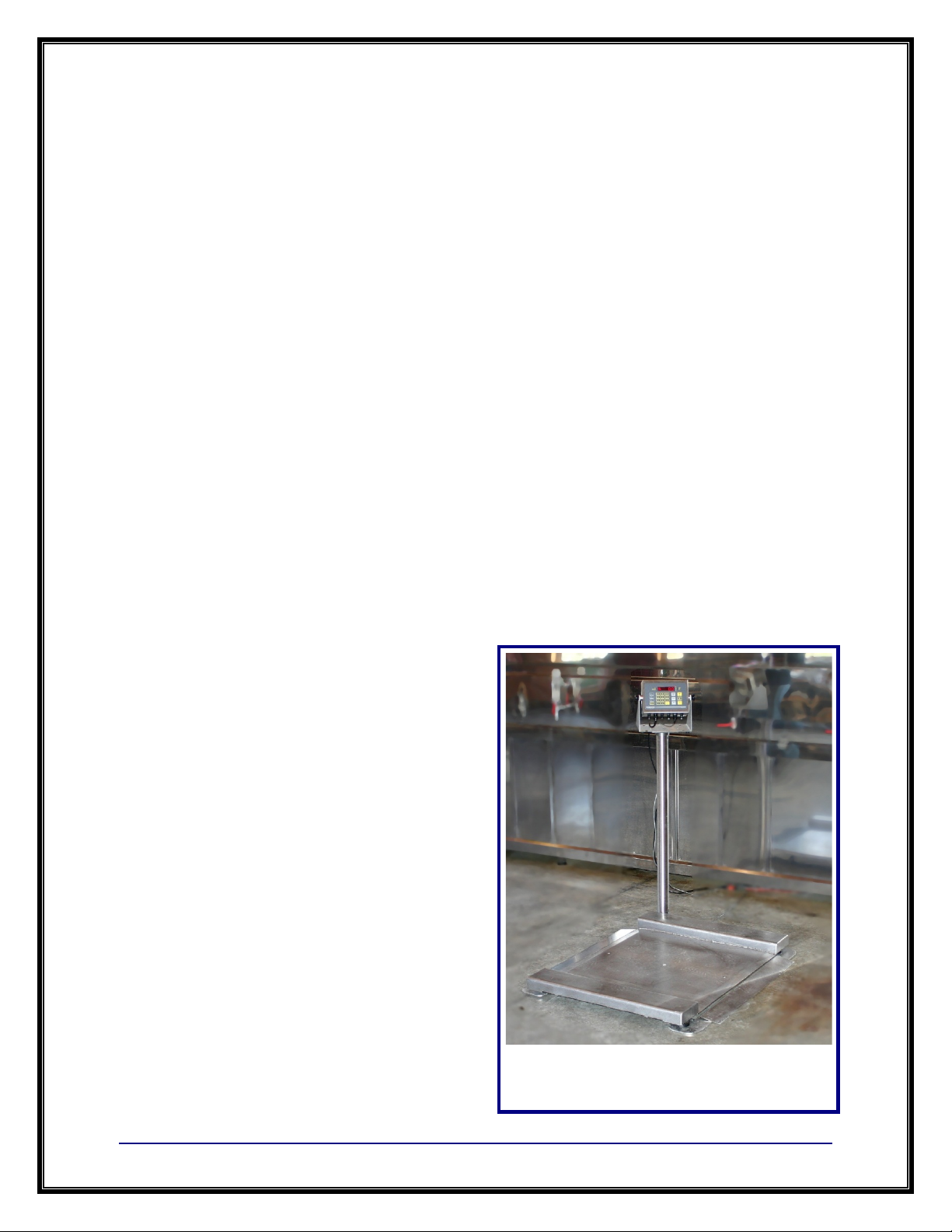
Aegis Drum Scale shown with FB 2200 Indicator
Wheel Kit.
Section 2: Scale Installation
2.1. OVERVIEW
2.1.1. Physical Installation Notes
• Only those charges which are incurred as a result of the equipment's
inability to be adjusted to performance specifications may be charged to
warranty.
• No physical alterations (mounting holes, etc.) are permitted during installation.
The installing technici a n is res pons ible that all personnel are fully
trained and familiar with the equipment's capa bilities and
limitations before the installation is considered com plete.
• All electrical assemblies must be replaced as assemblies or units.
─ Replacement of individual components is not permitted.
─ These components must be returned intact for replacement credit using the
standard procedures.
• At the time of installation, all
electronic and mechan i cal
adjustments are considered to be
part of the installation, and are
included in the installation
charge(s).
• The AC receptacle/outlet shall be
located near the Indicator and
easily accessible.
• Electrical connections other than
those specified may not be
performed.
04/10 11 51190 Rev. 2
and optional
 Loading...