

Fairbanks Aegis Coil Scales User Manual

Installation Manual
Aegis Coil Scale
© 2008-2010 by Fairbanks Scales, Inc. Revision 2 04/10
All rights reserved
51205


Amendment Record
AEGIS COIL SCALE
Document 51205
Manufactured by Fairbanks Scales Inc.
821 Locust
Kansas City, Missouri 64106
Created 10/08 Created Document
Revision 1 12/08 Documentation Release
Revision 2 04/10 Updated cradle drawings, p arts list, and per ECO 637.

Disclaimer
Every effort has bee n made to provide com plete and accurate inform ation in this manual. However,
although this manual m ay include a specifically iden tified warranty notice for the produc t, Fairbanks
Scales makes no representations or warranties with respect to the contents of this manual, and
reserves the right to make changes to this manual without notice when and as improvements are
made.
Fairbanks Scales shal l not be liable f or any loss, damage, c ost of repairs, inc idental or conseq uential
damages of any kind, whether or not based on express or implied warrant y, contract, negligence, or
strict liability arising in connection with the design, development, installation, or use the scale.
© Copyright 2008-2010
This document contains proprietary information protected by copyright. All rights are reserved; no part
of this manual may be reproduced, copied, translated or transmitted in any form or by any means
without prior written permission of the manufacturer.

Table of Contents
SECTION 1: GENERAL INFORMATION .................................................................. 6
1.1. Introduction ................................................................................................................ 6
SECTION 2: GENERAL SERVICE POLICY.............................................................. 9
2.1. General Service Policy ............................................................................................... 9
SECTION 3: SCALE INSTALLATION ...................................................................... 11
3.1. Conferring with Our Client ........................................................................................ 11
3.2. Standard Installation Steps ...................................................................................... 13
SECTION 4: ELECTRICAL INSTALLATION ........................................................... 22
4.1. Introduction .............................................................................................................. 22
4.2. Wiring the Junction Box ........................................................................................... 24
4.3 Grounding the Scale ................................................................................................. 26
4.4. Installing Accessories .............................................................................................. 27
SECTION 5: SERVICE & MAINTENANCE .............................................................. 29
5.1. Recommended Preventive Maintenance Schedule .................................................. 29
5.2. Troubleshooting ....................................................................................................... 30
5.3. Scale Platform Troubleshooting ............................................................................... 31
SECTION 6: PARTS ................................................................................................. 33
6.1. Platform Model Matrix .............................................................................................. 33
6.2. Parts List .................................................................................................................. 34
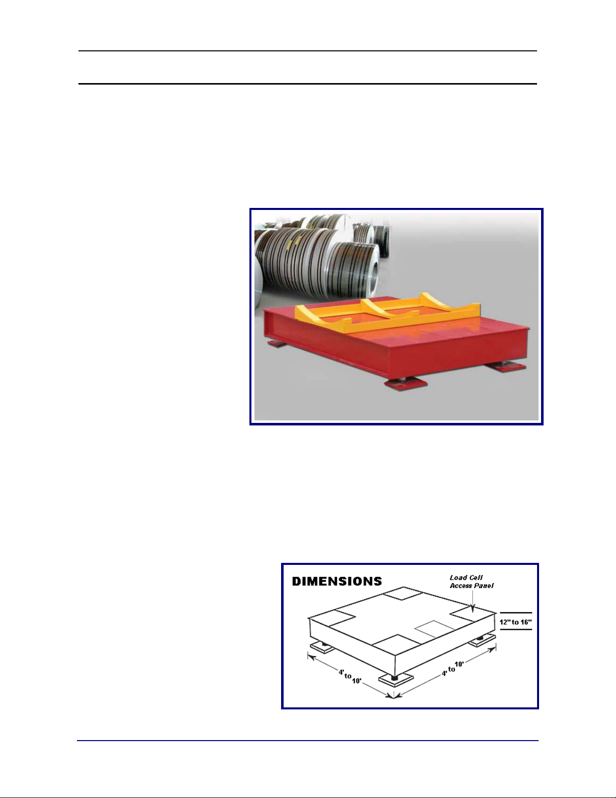
6.3. Dimensions Diagram ................................................................................................ 35
6.4. Accessory Part Lists ................................................................................................ 36
6.5. Accessory Part Drawings ......................................................................................... 37
04/10 5 51205 Rev. 2
Section 1: General Information
1.1. INTRODUCTION
The Aegis Coil Scale is an extremely rugged floor scale, designed for high
capacities and a wide variation of dimensional sizes.
• The Aegis Coil Scale was designed for weighing coils (steel, copper, aluminum,
etc.).
• It features a free-floating
platform and rocker
column load cell design.
• Its smooth deck platform
is designed for
concentrated loads an d
harsh working
environments found at
steel mills and
manufacturing plants.
• It is designed for
applications 12” to 16”
above grade.
Aegis Coil Scale is designed for applications with high load concentrations.
The
• General Industrial • Heavy-Duty Industrial • Warehousing
• Extremely Heavy Point
Loading that bends or
dimples normal platforms
• When Impact Loading is
necessary, dropping the
product onto the scale
• Weighing steel, aluminum, or
copper coil, as well as billets,
castings and cable spools
04/10 6 51205 Rev. 2
Feature
Description
Standard Platform Sizes
4’ x 4’ thru 10’ x 10’
Platform Height
12” to 16” Smooth Tread
Deck Thickness
¼” to ½” Plate
Scale Capacities
30,000 to 80,000 lbs.
Overload Capacity
300%
Sideload Protection Rating
100%
Humidity
10 to 100%
Accuracy
Platform Accuracy up to 0.02%
Load Cell Excitation
5 to 15 VDC
Grounding
Less than 3 Ohms to True Earth Ground
1.1.1. Specifications
Section 1: Gen er al Information
Temperatures
Scale Construction
Junction Box
Load Cells
Interface Cable
Approvals
• Operating: -10°C to 40°C (14°F to 104°F)
• Storage: -20°C to 70°C (-4°F to 158°F)
• Type A36 carbon steel
• Deck plate – ¼”,
• Analog
• Stainless Steel
• NEMA 4X
• Four (4) Rocker Column Design
• IP69K – “True” Hermetically Sealed, with the highest ingress
protection available
• 17-4 PH Stainless Steel
• 15,000 to 50,000 Capacity
• Combined Error -- ≤ ±0.02% of Rated Capacity
31’ PVC Jacketed
• FM Approved
• NTEP Approval CC# 07-097 (for 6,000 divisions)
• Load Cell NTEP Appro val CC# 07-037
3
/8”, ½”
04/10 7 51205 Rev. 2
Section 1: Gen er al Information
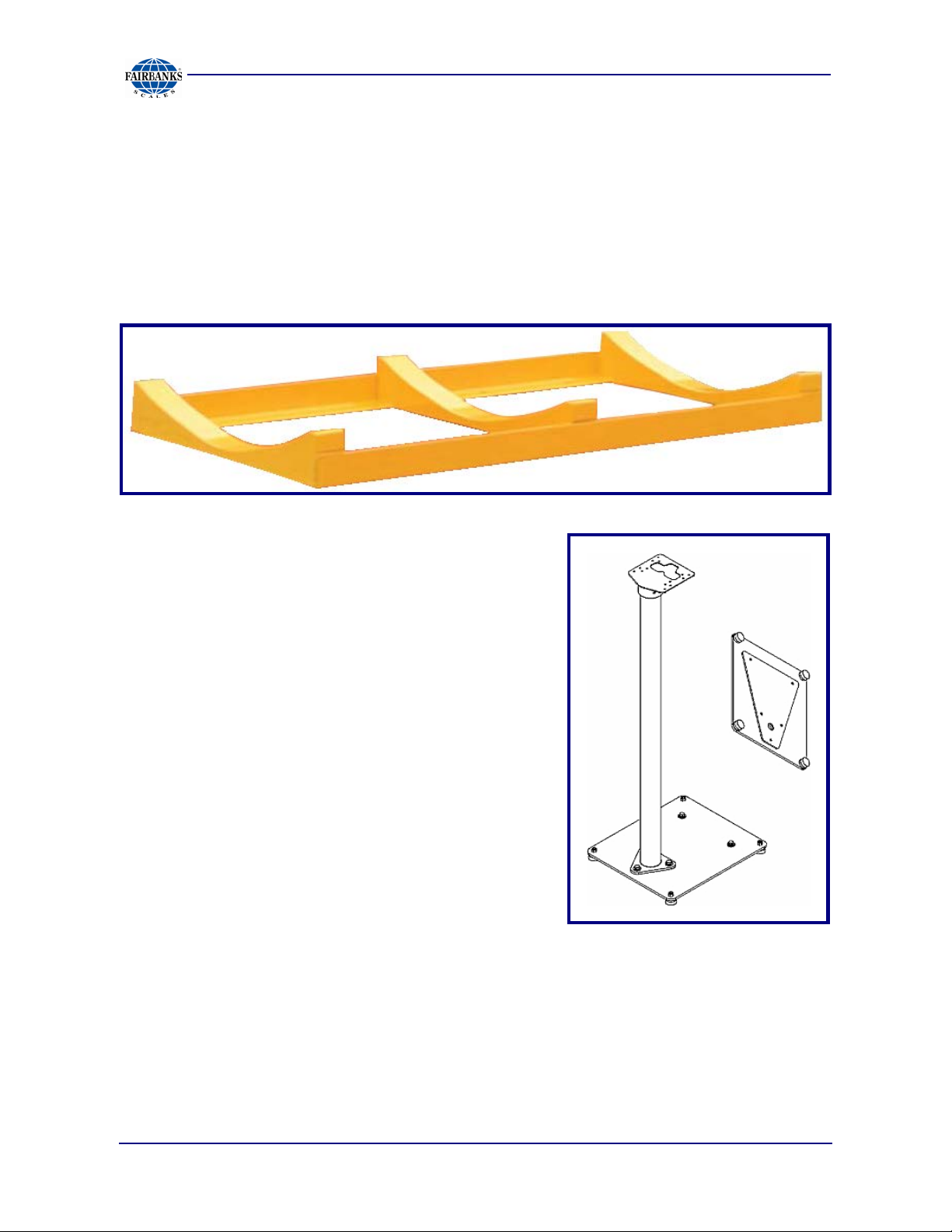
• Coil Cradle
• Intrinsically Safe Controller
• Stand-alone Instrument Pillar
• Smart Sectional Controller
• QMB
1.1.2. Accessories
Available modifications and accessories include the following:
04/10 8 51205 Rev. 2
Absolutely NO physical, electrical or program modifications other
Section 2: General Service Policy
2.1. GENERAL SERVICE POLICY
Prior to installation, always verify that the
equipment satisfies the customer's
requirements as supplied, and as described
in this manual.
If the equipment cannot satisfy the application and the application cannot be
modified to meet the design parameters of the equipment, the installation
should NOT be attempted.
It is the customer/operator's responsibility to ensure the
equipment provided by Fairbanks is operated within the para m e ters
of the equipment's specifications and protected from accidental or
malicious damage.
than selection of standard options and accessories can be made
by customers to this equipment
Repairs are performed by Fairbanks Scales Service Technicians
and Authorized Distri but or P er s onne l ONLY!
WARNING!
Failure to comply with this poli c y voids al l im pli e d a nd/or written
warranties
04/10 9 51205 Rev. 2
Section 2: General Servic e P olicy
2.1.1. Service Technician’s Responsibilities
• All electronic and mechanical calibrations and/or
adjustments required for making this equipment
perform to accuracy and operational specifications
are considered to be part of the original installation.
─ They are included in the installation charge.
─ Only those charges which are incurred as a result
of the equipment's inabil ity to be adjusted or
calibrated to per for ma nc e spec ifications may be
charged to warranty.
• The equipment consists of printed circuit assemblies which must be handled
using ESD handling procedures, and must be replaced as units.
─ Replacement of individual components is not allowed.
─ The assemblies must be properly packaged in ESD protective material and
returned intact for replacement credit per normal procedures.
2.1.2. Users’ Responsibility
Absolutely no physical, electrical or program modifications ot he r
than selection of standard options and accessories are to be
made to this equipment.
04/10 10 51205 Rev. 2
Section 3: Scale Installation
3.1. CONFERRING WITH OUR CLIENT
• The technician must be prepared to recommend the arrangement of components
which provide the most efficient layout, utilizing the equipment to the best possible
advantage.
• Assist the customer in selecting a site which allows easy access to and from the
scale.
─ The site needs good drainage away from the scale, elevated enough so the
surrounding areas drain away from the scale.
• Explain and review the warranty policy with the customer.
The installing technician is responsi ble that all personnel are
fully trained and familiar wi t h the e quipme nt 's capa bilities and
limitations before the installation is considered com plete.
• All electrical assemblies must be returned intact for replacement credit using the
standard procedures.
• At the time of installation, all electronic and mechanical adjus t m ents are
considered to be part of the installation, and are included in the installation
charge(s).
• The AC receptacle/outlet shall be located near the Indicator and easily accessible.
• Electrical connections other than those specified may not be perf ormed.
04/10 11 51205 Rev. 2
Section 3: Scale I ns tallation
• All load cells, load cell cables and interconnecting cables used to connect all
scale components shall be located a minimum of thirty-six (36”) inches
distance away
electric current carrying conductors.
• This includes digital weight indicators, junction boxes, sectional
controllers, and power supplies.
• This includes any peripheral devices, such as printers, remote
displays, relay boxes, remote terminals, card readers, and
auxiliary data entry devices.
• Also included is the scale components themselves, such as
120 volt AC, 240 volt AC, 480 volt AC and electric supply of
higher voltage wiring runs and stations, AC power transformers,
overhead or buried cables, electric distribution panels, electric
motors, florescent and high intensity lighting which utilize
ballast assemblies, el e ct r ic heating equipment, traffic light
wiring and power, and relay boxes.
IMPORTANT INSTALLATION NOTICE
from all single and multiple phase high energy circuits and
• All scale components, including digital weight indicators and
peripheral devices are not des igned to operate on internal combustion engine
driven electric generators and other similar equipment.
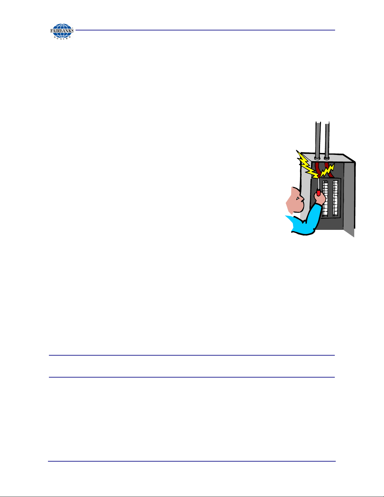
Electric arc welding can severely damage scale
components such as digital wei ght indi c a t ors, junction
boxes, sectional control lers, power supplies, and load
cells.
NOTE: For additional information, please contact your Fairbanks Scales
Service Representative.
04/10 12 51205 Rev. 2

Section 3: Scale I ns tallation
3.2. STANDARD INSTALLATION STEPS
The Aegis Coil Scale Platform standard installation consists of the following
steps.
A. Unpack scale, and check off all components.
B. Prepare tools, materials and documentation.
C. Select site location.
D. Foundation check, layout, and base plate setting.
E. Set up deck.
F. Set deck on load cells.
G. Level platform.
H. Install and wire instrument to platform.
I. Adjust and calibrate scale according to appropriate indicator service
manual.
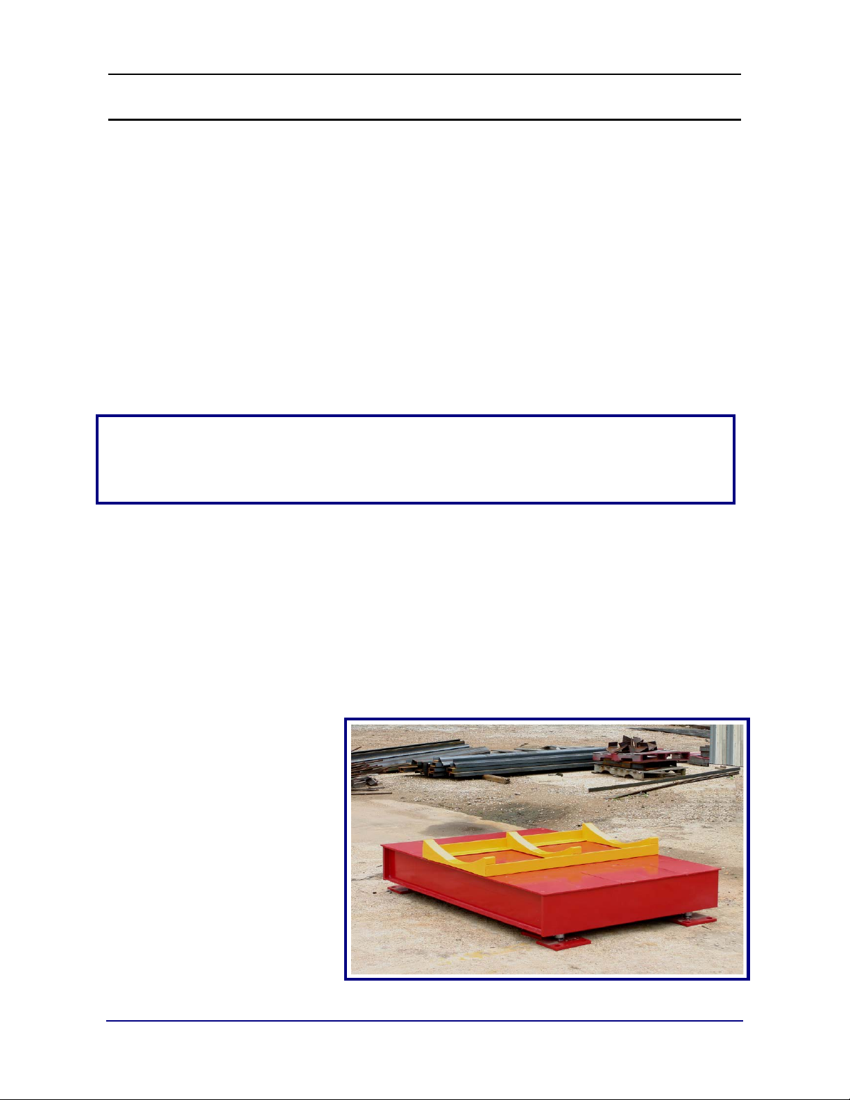
J. Install coil cradle (if applicable).
3.2.1. Standard Components
The Aegis Coil Scale Platform is shipped with these standard components:
• The Weighbridge Platform
• Load Cells
• Load Cell Base Plates
• Side Checking Assemblies
• Mounting Hardware
• Analog Junction Box
04/10 13 51205 Rev. 2
 Loading...