

Page 1
Installation Manual
Omnicell
Models: 9110
© 2008 by Fairbanks Scales Inc.
All rights reserved
50766
Revision 2 01/08
Page 2

50766 2 01/08 Rev. 2
Amendment Record
Omnicell 9110
50766
Manufactured by Fairbanks Scales Inc.
821 Locust
Kansas City, Missouri 64106
Issue #1 New Product
Revision 2 Inserted Load Cell Wiring Chart
Disclaimer
Every effort has been made to provide complete and accurate information in this manual. However, although this manual may include
a specifically identified warranty notice for the product, Fairbanks Scales makes no representations or warranties with respect to the contents of this manual, and reserves the right to make changes to this manual without notice when and as improvements are made.
Page 3

50766 3 01/08 Rev. 2
Table of Contents
Section 1: General Information
A. Introduction . . . . . . . . . . . . . . . . . . . . . . . . . . . . . . . . . . . . . . . 4
B. Specifications . . . . . . . . . . . . . . . . . . . . . . . . . . . . . . . . . . . . . . 4
C. Accessories . . . . . . . . . . . . . . . . . . . . . . . . . . . . . . . . . . . . . . . 4
Section 2: Installation
A. General Service Policy . . . . . . . . . . . . . . . . . . . . . . . . . . . . . . 5
B. Overview . . . . . . . . . . . . . . . . . . . . . . . . . . . . . . . . . . . . . . 5
C. Unpacking . . . . . . . . . . . . . . . . . . . . . . . . . . . . . . . . . . . . . 5
D. Installation Instruction . . . . . . . . . . . . . . . . . . . . . . . . . . . . . . . 6
Section 3: Parts List
A. Parts List . . . . . . . . . . . . . . . . . . . . . . . . . . . . . . . . . . . . . . . . 10
B. Accessories . . . . . . . . . . . . . . . . . . . . . . . . . . . . . . . . . . . . . . 10
Appendix 1: Models . . . . . . . . . . . . . . . . . . . . . . . . . . . . . . . . . . . . . . . 12
Page 4

50766 4 01/08 Rev. 2
A. Introduction
Fairbanks Omnicell 9110 Series tank weighing assembly is made for low capacity, non-commercial weighing applications. It features an exclusive slider plate design that eliminates problems
caused from thermal expansion.
OMNICELL® 9110 SERIES TANK WEIGHING ASSEMBLY FEATURES
• Capacities available from 45 lbs to 225 lbs.
• Sliding system with 2-directional bumpers.
• Low profile design.
• Load cells sealed to industry’s highest standard for environmental protection.
• Load cell constructed of 17-4 stainless steel for high caustic protection.
• Mounts available in 304 stainless and zinc plated steel.
• Factory Mutual approved for hazardous applications.
• Patented MV/V/Ohm calibration for ease of installation.
• Designed for non-commercial applications.
B. Specifications
Mount Construction . . . . . . . . . . . . . . . . . . . 304 stainless steel;
zinc plated mild steel
Capacities . . . . . . . . . . . . . . . . . . . . . . . . . . 45 lb, 112 lb, 225 lb.
Full Scale Output (FSO) . . . . . . . . . . . . . . . 2.0mV/v ± 0.05%
Combined Error (FSO) . . . . . . . . . . . . . . . . <
0.03%
Non-Linearity (FSO) . . . . . . . . . . . . . . . . . . 0.02%
Hysteresis (FSO). . . . . . . . . . . . . . . . . . . . . 0.02%
Creep Error (30 min.) . . . . . . . . . . . . . . . . . <
0.05%
Compensated Temperature . . . . . . . . . . . . . 14° F to 104° F (-10° C to 40° C)
Operating Temperature . . . . . . . . . . . . . . . . -40° F to 176° F (-40° C to 80° C)
Excitation Voltage . . . . . . . . . . . . . . . . . . . . 5-15 VDC
Overload . . . . . . . . . . . . . . . . . . . . . . . . . . . Safe = 150%; ultimate = 300%
Sideload . . . . . . . . . . . . . . . . . . . . . . . . . . . Safe = 100%
Bridge Resistance . . . . . . . . . . . . . . . . . . . . 1000 ohms nominal
Load Cell Construction . . . . . . . . . . . . . . . . Stainless Steel 17-4 PH
Sealing . . . . . . . . . . . . . . . . . . . . . . . . . . . . Hermetic seal;
Cable entry sealed by glass to metal header
Load Cell Cable. . . . . . . . . . . . . . . . . . . . . . 20 ft., polyurethane
Protection . . . . . . . . . . . . . . . . . . . . . . . . . . IP 68
Approvals . . . . . . . . . . . . . . . . . . . . . . . . . . Factory Mutual
C. Accessories
Mild Steel Uplift Protection with bolts. . . . . . .25458
Stainless Steel Uplift Protection with bolts. . .25459
Section 1: General Information
Page 5

50766 5 01/08 Rev. 2
A. General Service Policy
Prior to installation, it must be verified that the equipment will satisfy the customer's require-
ments as supplied, and as described in this manual. If the equipment cannot satisfy the application
and the application cannot be modified to meet the design parameters of the equipment, the installation should not be attempted.
It is the customer / operator's responsibility to ensure the equipment provided by Fairbanks is
operated within the parameters of the equipment's specifications and protected from accidental or
malicious damage. Other than the procedures authorized in the Operating manual, no service,
repair, or adjustments may be performed by unauthorized / untrained service personnel. Any unauthorized repairs will void any verbal, implied, or written warranties.
B. Overview
1. These instructions apply to the specific installation procedures. The procedures for instruments, printers and other peripherals are given in manuals specifically provided for those units.
2. All electronic and mechanical calibrations and or adjustments required to make this equipment perform to accuracy and operational specifications are considered to be part of the installation,
and are included in the installation charge. Only those charges which are incurred as a result of the
equipment's inability to be adjusted or calibrated to performance specifications may be charged to
warranty.
3. Absolutely no physical or electrical modifications are to be made to this equipment. Electrical
connections other than those specified may not be performed, and physical alterations are not
allowed.
4. Before the installation is considered complete, the equipment is to be installed to meet or
exceed any applicable weights and measures requirements, if applicable. The installing technician is
responsible to make certain customer personnel are fully trained and familiar with the capabilities
and limitations of the equipment. Be prepared to recommend the arrangement of components which
will provide the most efficient layout, utilizing the equipment to the best possible advantage. The
warranty policy must be explained and reviewed with the customer.
C. Unpacking
1. Check that all components are on hand, and agree with the customer's order.
2. Remove all components from their packing material, checking to make certain that all parts
are accounted for and no parts are damaged. Advise the shipper immediately, if damage has
occurred. Order any parts necessary to replace those which have been damaged. Keep the shipping
container and packing material for future use. Check the packing list.
Section 2: Installation
Page 6

50766 6 01/08 Rev. 2
D. Installation Instruction
1. Items not Supplied
a. 1/4-20 UNC bolts- 4 required for each assembly
b. 5/16-18 UNC Anchors/ bolts - 2 required for each assembly
2. Raise the vessel to be supported by the Omnicell® assemblies and secure by safely
blocking the vessel to the required height. See Figure 50766-1.
3. Place each Omnicell® assembly onto a level surface under each support leg.
4. Set the assemblies for the correct orientation as per Figure 50766-2.
5. Adjust the load lifting/ support bolt until it is against the top plate. Insert the four (4)
1/4-20 bolts and loosely tighten the bolts to the support leg for each assembly.
6. Mark the location of the anchor bolt locations. Slide the assembly back and drill the anchor
hole locations. Re-position the load cell assembly, level, and anchor all assemblies.
7. Lower the vessel onto the top plate of each Omnicell® assembly. Tighten the bolts securing
the load plates to each support leg of the vessel. Remove all cribbing blocks. Lower the load
lifting/ support bolts on each assembly until the bolt has approximately 1/4” clearance and the
load cell is bearing the vessel’s weight.
8. Route the cables to the junction box and indicator. Wire the Omnicell® assemblies according
to the appropriate junction box and indicator service manual. Calibrate as required.
WARNING:
The Omnicell®assemblies MUST be orientated as per Figure 50766-2 or severe damage could
occur to the vessel or assemblies.
Load Cell Wiring
+ EXC = Green
- EXC = Black
+ SIG = White
- SIG = Red
Page 7

50766 7 01/08 Rev. 2
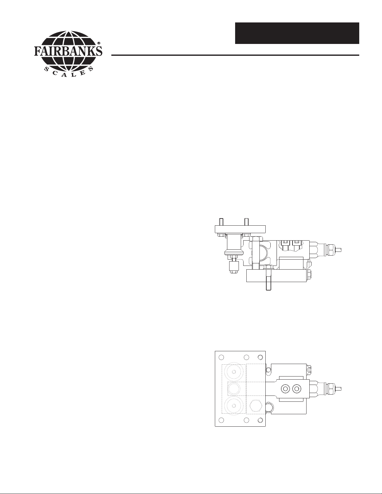
LOAD LIFTING BOLT
GROUNDING LUG
TOP MOUNTING PLATE
5/16-18" UNC (2x)
(not provided)
(optional)
BASE PLATE
UPLIFT PROTECTION
3.54"
5.71"
1/4-20" UNC (4x) (not provided)
2.17"1.18"
1.57"
3.15"
.79"
.31" (4x)
.31"
.79"
4.72"
3.94"
2.35"
.47"
50766-1
Top Mounting Plate
Base Plate
Load Lifting Bolt
Grounding Cable
Side Checking
Uplift Checking
1/4-20 Hex Bolt
50766-3
Page 8

50766 8 01/08 Rev. 2
Figure 1
2-directional
bumper module
Figure 5
Figure 9
Figure 2
Figure 6 Figure 7
Figure 3
Figure 8
Figure 4
1. Each individual "2-directional bumper module" can be installed rotated 180
around it’s loading point.
2. For scales with 3 modules, distances to center of gravity should be chosen with
ratio 1:2, as shown in figure 1, which gives even load distribution.
3. For best stability, the loading points of the modules should be as far from one
another as the scale structure allows.
gravity
Center of
Load carrier symbol
2 x
120
L
L
50766-2
Page 9

50766 9 01/08 Rev. 2
This page was intentionally left blank.
Page 10

50766 10 01/08 Rev. 2
A. Parts List
Item Part Number Description Capacities
1 25521 Load cell, SS Hermetically Sealed 45 lb
25522 Load cell, SS Hermetically Sealed 112 lb
25523 Load cell, SS Hermetically Sealed 225 lb
2 3-6856-A Grounding cable w/ bolts ALL
3 4-6851-1 Sliding plate ALL
4 4-6841-1 Sliding loading pin ALL
6 FL M8x35-8.8 Load cell mounting bolts Mild Steel
FL M8x35-A4-20-80 Load cell mounting bolts Stainless Steel
B. Accessories
Item Part Number Description Capacities
5 25458 Mild Steel Uplift w/ bolts ALL
25459 Stainless Steel Uplift w/ bolts ALL
Section 3: Parts List
Page 11

50766 11 01/08 Rev. 2
50766-4
2
1
3
5
4
6
Page 12

50766 12 01/08 Rev. 2
A. Mild Steel
Product Number Description
25432 Omnicell, w/ Zinc plated mild steel, ss hermetic load cell, 45 lb capacity
25433 Omnicell, w/ Zinc plated mild steel, ss hermetic load cell, 112 lb capacity
25434 Omnicell, w/ Zinc plated mild steel, ss hermetic load cell, 225 lb capacity
B. Stainless Steel
Product Number Description
25435 Omnicell, stainless steel mount, ss hermetic load cell, 45 lb capacity
25436 Omnicell, stainless steel mount, ss hermetic load cell, 112 lb capacity
25437 Omnicell, stainless steel mount, ss hermetic load cell, 225 lb capacity
Appendix I : Models
 Loading...