

Page 1
Service/Installation
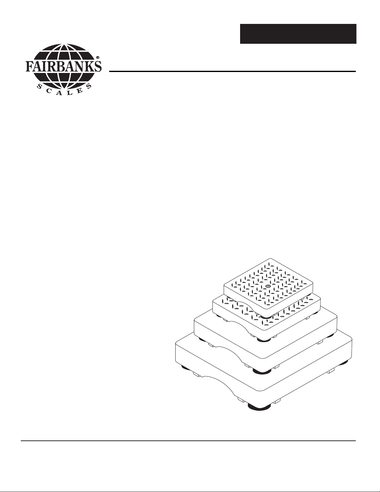
Delta Series
Analog Platforms
Model: 6001
50661
Issue #4 12/04
© 2004 by Fairbanks Scales Inc.
All rights reserved
Page 2

50661 2 12/04 Issue #4
Amendment Record
Delta Series Analog Platforms
Model 6001
50661
Manufactured by Fairbanks Scales Inc.
821 Locust
Kansas City, Missouri 64106
Created 7/01 New Product
Issue #1 7/01 New Product
Issue # 2 9/01 Part numbers changed
Issue #3 11/03 Added new 24” x 24” models, Capacities and Graduation Sizes, Loadcell
Information, and COC #
Issue #4 12/04 Corrected errors
Disclaimer
Every effort has been made to provide complete and accurate information in this manual. However, although this
manual may include a specifically identified warranty notice for the product, Fairbanks Scales makes no
representations or warranties with respect to the contents of this manual, and reserves the right to make changes
to this manual without notice when and as improvements are made.
Page 3

50661 3 12/04 Issue #4
Table of Contents
Section 1: Introduction . . . . . . . . . . . . . . . . . . . . . . . . . . . . . 4
Section 2: Description . . . . . . . . . . . . . . . . . . . . . . . . . . . . . . 4
Section 3: Installation . . . . . . . . . . . . . . . . . . . . . . . . . . . . . . 5
Section 4: Parts Description . . . . . . . . . . . . . . . . . . . . . . . . . 6
Section 5: Parts . . . . . . . . . . . . . . . . . . . . . . . . . . . . . . . . . . .
A. 12” x 12” - 6 lb and 12 lb Capacities . . . . . . . . . . . . . . . 7
Diagram . . . . . . . . . . . . . . . . . . . . . . . . . . . . . . . . . . . . 8
B. 14” x 14” - 60 lb and 150 lb Capacities . . . . . . . . . . . . . 9
Diagram . . . . . . . . . . . . . . . . . . . . . . . . . . . . . . . . . . . 10
C. 18” x 18” - 100 lb and 300 lb Capacities . . . . . . . . . . . . 11
Diagram . . . . . . . . . . . . . . . . . . . . . . . . . . . . . . . . . . . . 12
D. 24” x 24” - 200 lb, 300 lb and 500 lbs . . . . . . . . . . . . . 13
Diagram . . . . . . . . . . . . . . . . . . . . . . . . . . . . . . . . . . . . 14
Appendix I: Size & Capacity Chart . . . . . . . . . . . . . . . . . . . . . 15
Appendix II: Schematic Diagram of PCB Junction . . . . . . . . . 16
Appendix III: Parts list: Original 24” X 24” . . . . . . . . . . . . . . . 17
Appendix IV: Loadcell Information . . . . . . . . . . . . . . . . . . . . . 19
Page 4

50661 4 12/04 Issue #4
Section 1: Introduction
Section 2: Description
The 6001 Series analog platforms are lightweight scale platforms
that feature matched loadcells.
The 12” x 12”, and the 14” x 14” platforms are constructed of a lightweight,
durable composite material.
The 18” x 18” platforms have a powder-coated steel platform cover for
added strength and durability.
The 24” x 24” size is constructed entirely of steel, that is also powder
coated.
The 6001 Series Platforms utilize 'matched' load cells making
cornering adjustment circuitry unnecessary. Their capacities range from 6
lbs to 500 lbs, in different four sizes:
Platform Size
Capacity Division Size
12” x 12" 6 lb 0.002 lb
12” x 12" 12 lb 0.005 lb
12” x 12" 25 lb 0.01 lb
14” x 14” 60 lb 0.02 lb
14” x 14” 150 lb 0.05 lb
18” x 18” 100 lb 0.05 lb
18” x 18” 300 lb 0.1 lb
24” x 24” 200 lb 0.1 lb
24” x 24” 300 lb 0.1 lb
24” x 24” 500 lb 0.2 lb
The 6001 Series Analog platform will easily interface to most any analog
indicator. All models are approved for commercial use by NTEP COC # 99197A2.
Page 5

50661 5 12/04 Issue #4
Section 3: Installation
The platforms are shipped ready to interface to an analog indicator. All
models use the same wiring color code.
1. Place the platform where it will be used
2. Level the platform using the feet
3. Connect the Interface cable to the indicator. The loadcell interface
cable is identified as follows:
Platform T
ermination Wire Color Function
TB1-2 Black (-) Excitation
TB1-1 Green (+) Excitation
TB1-3 Yellow Outer Shield-Grd
N/A Bare
Inner Shield-Chassis Grnd
TB1-4 White (+) Signal
TB1-5 Red (-) Signal
Page 6

50661 6 12/04 Issue #4
TOOLS
REQUIRED:
• #1 Phillips
screwdriver
• 7/64” Allen
wrench
Section 4: Parts Replacement
A. Load Cell Replacement:
1. Remove power to the indicator.
2. Set the platform up-side-down, unscrew and remove all four feet.
3. Use a 7/64” allen wrench to remove the screws in the foot holes.
4. Place the platform upright without the cover.
5. Unplug the suspect load cell from the load cell junction assy.
6. Remove the screws holding the load cell and spacer in place.
7. Remove the load cell and cable.
NOTE the cell and cable placement!
8. Install the new load cell and the spacer(s).
9. Tighten the load cell mounting screws to 8 ( ± 2 ) INCH/LBS of
torque ONLY.
10. Route the load cell cable exactly as the original's cable & plug
connector in.
11. Place the base up-side-down into the platform cover and align
the holes.
12. Insert the allen head screws and tighten to 8 (± 2 ) INCH/LBS of
torque ONLY.
13. Calibrate the indicator.
Page 7

50661 7 12/04 Issue #4
Section 5: Parts
A. 12” x 12” (6 lb, 12 lb and 25 lb Capacities):
Item
No.
Part No. Description Capacity
1 18221 Assy, 12" base 6, 12, 25
2 22424 Load Cell Junction PCB 6, 12, 25
3 18181 Platform, 12 x 12 6, 12, 25
4 22315 Load Cell, 3 lb 6
4 22316 Load Cell, 6.25 lb 12
4 22317 Load Cell, 12.5 lb 25
5 18193 Shim 6, 12, 25
6 14233 Foot 6, 12, 25
7 19779 Load Mount 6
7 19780 Load Mount 12
7 19781 Load Mount 25
8 18963 Screw #7-18 x .47 Plastite 6, 12, 25
9 10965 #6-32 x .31 Cap Head 6, 12, 25
10 11495 Nylon Washer 6, 12, 25
11 22421 Cover Plate 6, 12, 25
12 22568 Nameplate 6
12 22569 NamePlate 12
12 22570 Serial Tag 25
14 17624 Cable Clip 6, 12, 25
15 22564 Cable Assembly 6, 12, 25
16 22565 Adhesive Mount Spacer 6, 12, 25
*17 20791 Nominal Capacity Label 6
*17 20792 Nominal Capacity Label 12
*17 20793 Nominal Capacity Label 25
18 18886 Label 6, 12, 25
19 17545 Liquid Tight Connector 6, 12, 25
* Parts Inquiry. Must furnish Original Serial Number.
Page 8

50661 8 12/04 Issue #4
A. 12” x 12” (6 lb, 12 lb and 25 lb Capacities):
50661-1
Page 9

50661 9 12/04 Issue #4
B. 14” x 14” (60 lb and 150 lb Capacities):
Item
No.
Part No. Description Capacity
1 18222 Assy, 14" base 60, 150
2 22424 Load Cell Junction PCB 60, 150
3 18182 Platform, 14 x 14 60, 150
4 22318 Load Cell, 25 lb 60
4 22319 Load Cell, 37.5 lb 150
5 18193 Shim 60, 150
6 14233 Foot 60, 150
7 20323 Load Mount 60
7 15758 Load Mount 150
8 18963 Screw #7-18 x .47 Plastite 60, 150
9 10965 #6-32 x .31 Cap Head 60, 150
10 11495 Nylon Washer 60, 150
11 22421 Cover Plate 60, 150
12 22571 Nameplate 60
12 22572 NamePlate 150
14 17624 Cable Clip 60, 150
15 22564 Cable Assembly 60, 150
16 22565 Adhesive Mount Spacer 60, 150
*17 20795 Nominal Capacity Label 60
*17 22595 Nominal Capacity Label 150
18 18886 Label 60, 150
19 17545 Liquid Tight Connector 60, 150
* Parts Inquiry. Must furnish Original Serial Number.
Page 10

50661 10 12/04 Issue #4
B. 14” x 14” (60 lb and 150 lb Capacities):
50661-2
Page 11

50661 11 12/04 Issue #4
C. 18” x 18” (100 lb and 300 lb Capacities):
Item
No.
Part No. Description Capacity
1 18249 Assy, 18" base 100, 300
2 22424 Load Cell Junction PCB 100, 300
3 22580 Platform, 18 x 18 100, 300
4 22320 Load Cell, 50 lb 100
4 22005 Load Cell, 75 lb 300
5 18194 Shim 100, 300
6 14233 Foot 100, 300
7 15758 Load Mount 100, 300
8 18963 Screw #7-18 x .47 Plastite 100
8 18966 Screw #7-18 x .63 Plastite 300
9 10965 #6-32 x .31 Cap Head 100
9 10315 #6-32 x .38 Cap Head 300
10 11495 Nylon Washer 100, 300
11 22421 Cover Plate 100, 300
12 22573 Nameplate 100
12 22574 NamePlate 300
14 17624 Cable Clip 100, 300
15 22564 Cable Assembly 100, 300
16 22565 Adhesive Mount Spacer 100, 300
*17 20795 Nominal Capacity Label 100
*17 22582 Nominal Capacity Label 300
18 18886 Label 100, 300
19 17545 Liquid Tight Connector 100, 300
20 22583 Platform Spacer 100, 300
21 22592 Washer 100, 300
22 17617 Cable Tie Mount 100, 300
23 17615 Cable Tie 100, 300
24 18963 Screw, #7-18 x ,47 Plastite100, 300
25 11920 Screw Adhesive 100, 300
* Parts Inquiry. Must furnish Original Serial Number.
Page 12

50661 12 12/04 Issue #4
C. 18” x 18” (100 lb and 300 lb Capacities):
50661-3
Page 13

50661 13 12/04 Issue #4
D. 24” x 24” (200 lbs, 300 lbs and 500 lb Capacities):
Item
No.
Part No. Description Capacity
1 24118 Base Assy 200, 300, 500
2 24119 Platform Assy 200, 300, 500
4 22424 L.C. Junction PCB Assy 200, 300, 500
7 22320 Load Cell, 50 lb 200
22005 Load Cell, 75 lb 300
22321 Load Cell, 125 lbs 500
8 18194 Shim 200, 300, 500
9 22583 Spacer 1.00 dia. 200, 300, 500
10 15758 Load Mount 200, 300, 500
11 24124 Cable Holder Plate 200, 300, 500
13 22564 Cable Assembly 200, 300, 500
14 11263 Cable Clip 200, 300, 500
15 11272 Spacer 200, 300, 500
16 17566 Spacer 6-32 x .63 200, 300, 500
17 11039 Spacer, Level Bubble 200, 300, 500
18 23268 Bullseye Level 200, 300, 500
19 22905 Bubble Level Holder 200, 300, 500
22 10895 Screw 6-32 x .38 Pan 200, 300, 500
23 10315 Screw 6-32 x .38 Sckt 200, 300, 500
26 10103 Hex Nut 6-32 200, 300, 500
28 12777 Foot 200, 300, 500
30 10201 Washer, Lock Ext #6 200, 300, 500
32 22132 Retainer for Foot 200, 300, 500
*34 24127 Nameplate 200
24128 NamePlate 300
24129 NamePlate 500
* Parts Inquiry. Must furnish Original Serial Number.
Page 14

50661 14 12/04 Issue #4
D. 24” x 24” (200 lbs, 300 lbs and 500 lb Capacities):
14
(LC4)
30
22
(LC3)
13
11 15 16 30
4
5
R
W
1
Y
B
G
16
15
30
(LC1)
MIN
CAN
e
Made in U.S.A.
SEE
CAP
MAX
TEMP
n
C-O-C
RATING
1
5
Y
B
R
G
W
1
J1
J4
1
1
J2
J3
1
34
H000323CB
Fairbanks Scales
SERIAL
MODEL
CLASS
DETAIL
A
DETAIL A
SEE
DETAIL
B
17
18
19
20
(LC2)
DETAIL B
HANDLE HOLE
VIEW LOOKING THROUGH PLATFORM
24.28 SQ
2
1
32
28
NOTE: ALL LOADCELL CABLES TO BE RETAINED UNDER
THE PLATE AS TO NOT INTERFERE WITH THE
WEIGHING PLATFORM
SEE
DETAIL
C
50661-3A
10
GROUND
LUG
9
26
LOCK
30
WASHER
7
8
23
DETAIL C
Page 15

50661 15 12/04 Issue #4
Appendix I: Size & Capacity Chart
Product Size Platform Load Cell
No. (inches)
Capacity Rating
22402 12 x 12 x 2.28 6 lbs 3 lbs
22403 12 x 12 x 2.28 12 lbs 6.25 lbs
22405 14 x 14 x 2.38 60 lbs 25 lbs
2406 14 x 14 x 2.38 150 lbs 37.5 lbs
22407 18.28 x 18.28 x 2.64 100 lbs 50 lbs
22408 18.28 x 18.28 x 2.64 300 lbs 75 lbs
22409 24.28 x 24.28 x 2.68 200 lbs 50 lbs
22410 24.28 x 24.28 x 2.68 300 lbs 75 lbs
22411 24.28 x 24.28 x 2.68 500 lbs 125 lbs
24120 24.28 x 24.28 x 2.68 200 lbs 50 lbs
24125 24.28 x 24.28 x 2.68 300 lbs 75 lbs
24126 24.28 x 24.28 x 2.68 500 lbs 125 lbs
Page 16

50661 16 12/04 Issue #4
Appendix II: Schematic Diagram of PCB Junction
To
Instrument
TB1
L.C.2
L.C.1
J2
J1
J3
L.C.3
J4
L.C.4
50661-5
Page 17

50661 17 12/04 Issue #4
Appendix III: Original 24” x 24”
Item
No. Part No. Description Capacity
1 18250 Assy, 24" base 200, 300, 500
2 22424 Load Cell Junction PCB 200, 300, 500
3 22581 Platform, 24 x 24 200, 300, 500
4 22320 Load Cell, 50 lb 200
4 22005 Load Cell, 75 lb 300
4 22321 Load Cell, 125 lbs 500
5 18194 Shim 200, 300, 500
6 14233 Foot 200, 300, 500
7 15758 Load Mount 200, 300, 500
8 18963 Screw #7-18 x .47 Plastite 200
8 18966 Screw #7-18 x .63 Plastite 300, 500
9 10315 #6-32 x .38 Cap Head 200, 300, 500
10 11495 Nylon Washer 200, 300, 500
11 22421 Cover Plate 200, 300, 500
12 22575 Nameplate 200
12 22576 NamePlate 300
12 22577 NamePlate 500
14 17624 Cable Clip 200, 300, 500
15 22564 Cable Assembly 200, 300, 500
16 22565 Adhesive Mount Spacer 200, 300, 500
*17 20797 Nominal Capacity Label 200
*17 22582 Nominal Capacity Label 300
*17 20798 Nominal Capacity Label 500
18 18886 Label 200, 300, 500
19 17545 Liquid Tight Connector 200, 300, 500
20 22583 Platform Spacer 200, 300, 500
21 22592 Washer 200, 300, 500
22 17617 Cable Tie Mount 200, 300, 500
23 17615 Cable Tie 200, 300, 500
24 18963 Screw, #7-18 x ,47 Plastite 200, 300, 500
25 11920 Screw Adhesive 200, 300, 500
* Parts Inquiry. Must furnish Original Serial Number.
Page 18

50661 18 12/04 Issue #4
50661-4
Page 19

50661 19 12/04 Issue #4
Appendix IV: Loadcell Information
A
.41 TYP
1.43 REF
F
5 HOLES
1.004
REF
2.50
E
C
A
D
1.25
1.25
2.50
2.087
10.00
A
LOAD DIRECTION
PART # CAPACITY "A" "B" "C" "D"
22315 3.00 LB
22316
22317
22318 25 LB
22319
6.25 LB
12.5 LB
SECTION A-A
.258.160 .041
.160
.100
.160 .77
.064
N/A
N/A37.5 LB
.220
.195
.221.125 N/A
.207
.64
.72
.79
.74 .33 .180
50661-6
B
"E" "F"
.38 .180
.38
.33
.33
.180
.180
.196
Page 20

50661 20 12/04 Issue #4
0.180
Material 2024-13 Aluminum
Rated Output 0.9 mV/V NOMINAL
Matched output Ratio: 0.0009 mV/V/ohm +/- 0.05%
Combined Linearity and Hysterises +/- 0.020%
Non-Repeatability 0.01%
Creep in 20 Min 0.03%
Zero Balance +/- 0.30 mV/V
Data Temp Range +15 to +104 Deg F.
Terminal Resistance
INPUT 1193 +/- 5 ohms
OUTPUT 1000 +/- 5 ohms
INSULATION 5000 Meg Ohms @ 50 VDC MINIMUM
Max Load 213% of Cap without change of Characteristics
5 HOLES
.50
.50
D
LOADCELL
INPUTS
SHIELD
LOADCELL
OUTPUTS
D
C
24"
LOAD DIRECTION
LOADCELL WIRING
(+) EXC
(-) EXC
GND
(+) SIG
(-) SIG
1.875"
3.750"
BLACK
GREEN
YELLOW PIN 3
WHITE
RED
PIN 1
PIN 2
PIN 4
PIN 5
1.875"
A
PART #
22320
22321 125 LB
CAPACITY
50 LB
62.5 LB22004
75 LB22005
B
50661-7
"A"
.160 .998
.160
3.750"
3.010"
"B" "C"
.998
"D"
.745
.18
.677
.18
.18.720.998.190
.745.250 .984 .18
 Loading...