

Operating Manual
QuickSilver IS
5001 Series
50770
Revision 5 04/12
© 2012 by Fairbanks Scales Inc.
All rights reserved


Amendment Record
QuickSilver IS
5001 Series
50770
Manufactured by Fairbanks Scales Inc.
821 Locust Street
Kansas City, Missouri 64106
Issue 1 10/2004 New Product
Issue 2 08/2005 Revised commercial application specs
Issue 3 12/2006 Updated Minimum Grad Specifications List
Revision 4 08/2007 Updated images
Revision 5 04/2012 Added NTEP Approved Divisions, Control Drawings,
and updated Battery Charger information.
50770 3 04/12 Rev. 5

Table of Contents
Section 1: Introduction
A. Introduction …………………….........…………..… 5
Section 2: Description
A. Serial Tag Model Legends..............................…… 6
B. Specifications ………………………….........……… 6
Section 3: Unpacking and Assembly
A. Mounting …………………….........………....…..… 9
B. Assembly …………………….........………….....… 9
Section 4: Security
A. Security Levels ……………….........………....….... 10
Section 5: Operation
A. Keys ........…………………….........………....…..… 11
B. Indicators ....………………….........…………......… 12
C. Weighing .................…..……….........…………..… 12
Section 6: Battery Pack
A. Battery Pack Replacement .........………....…....… 17
B. Battery Pack Recharging …….........…………....... 17
C. Conditions ................…..……….........………….… 18
D. Specifications ....................................................... 18
Appendix I: FM Control Drawings (6) .............................. 19
Appendix II: Certificate of Compliance ........................... 25
Disclaimer
Every effort has been made to provide complete and accurate information in this manual. However, although this manual may
include a specifically identified warranty notice for the product, Fairbanks Scales makes no representations or warranties with
respect to the contents of this manual, and reserves the right to make changes to this manual without notice when and as
improvements are made.
50770 4 04/12 Rev. 5

Section 1: Introduction
50770 5 04/12 Rev. 5
The 5001 Series of bench scales and indicators have stainless steel construction. They are
designed for use in a hazardous area and/or wash-down environment. They either have a
direct power supply or can also use a battery. The scales feature the capacity to store up to
four (4) Over/Under Checkweighing Sequences in memory, each of which can be recalled at
the push of a button. Programming of these Over/Under Checkweighing can be made through
the front panel. The battery pack is stored in the battery holster located on the back of the
indicator which can be easily removed for recharging.

Section 2: Description
50770 6 04/12 Rev. 5
A. Serial Tag Model Legends:
P=Platform
P=Pillar (2nd "P")
I=Indicator or IND = Indicator Only
W=Wall Bracket
H =Hazardous Environment
Example: PWI = Platform + Wall bracket + Indicator
Example: PPI = Platform + Pillar + Indicator
Note: C = CSA approved (Canadian certification)
B. Specifications
1. Minimum Grad Size for Commercial Applications: NTEP Approval = 5000 Divisions
NTEP Appv’d LB KG OZ G
2.0000 X .0001 0.90715 X .00005 32.000 X .002 907.15 X .05
2.0000 X .0002 0.9072 X .0001 32.000 X .005 907.2 X .1
YES 2.0000 X .0005 0.9072 X .0002 32.00 X .01 907.2 X .2
6.0000 X .0001 2.72155 X .00005 96.000 X .005 2721.55 X .05
6.0000 X .0002 2.7215 X .0001 96.000 X .005 2721.5 X .1
6.0000 X .05 2.7216 X .0002 96.00 X .01 2721.6 X .2
6.000 X .001 2.7215 X .0005 96.00 X .02 2721.5 X .5
YES 6.000 X .002 2.722 X .001 96.00 X .05 2722 X 1
YES 6.000 X .005 2.722 X .002 96.0 X .1 2722 X 2
10.000 X .001 4.5360 X .0005 160.00 X .01 4536.0 X .5
YES 10.000 X .002 4.536 X .001 160.00 X .05 4536 X 1
YES 10.000 X .005 4.536 X .002 X .1 4536 X 2
12.000 X .001 5.4430 X .0005 192.00 X .02 5443.0 X .5
12.000 X .002 5.443 X .001 192.00 X .05 5443 X 1
YES 12.000 X .005 5.444 X .002 192.0 X .1 5444 X 2
24.000 X .001 10.8865 X .0005 384.00 X .02 10886.0 X .5
24.000 X .002 10.886 X .001 384.00 X .05 10886 X 1
YES 24.000 X .005 10.886 X .002 384.0 X .1 10886 X 2
YES 24.00 X .01 10.885 X .005 384.0 X .2 10885 X 5
YES 24.00 X .02 10.89 X .01 384.0 X .5 10890 X 10
YES 24.00 X .05 10.88 X .02 384 X 1 10880 X 10
25.000 X .001 11.3400 X .0005 400.00 X .02 113400 X 5
25.000 X .002 11.340 X .001 400.00 X .05 11340 X 1
YES 25.000 X .005 11.340 X .002 400.0 X .1 11340 X 2
30.000 X .001 13.6070 X .0005 480.00 X .02 136075 X 5
30.000 X .002 13.608 X .001 480.00 X .05 13608 X 1
30.000 X .005 13.608 X .002 480.0 X .1 13608 X 2

50770 7 04/12 Rev. 5
NTEP Appv’d LB KG OZ G
YES 30.00 X .01 13.610 X .005 480.0 X .2 13610 X 5
YES 30.00 X .02 13.61 X .01 480.0 X .5 13610 X 10
YES 30.00 X .05 13.60 X .02 480 X 1 13600 X 10
40.000 X .001 18.1440 X .0005 640.00 X .02 181440 X 5
40.000 X .002 18.144 X .001 640.00 X .05 18144 X 1
40.000 X .005 18.144 X .002 640.0 X .1 18144 X 2
YES 40.00 X .01 18.145 X .005 640.0 X .2 18145 X 5
YES 40.00 X .02 18.14 X .01 640.0 X .5 18140 X 10
YES 40.00 X .05 18.14 X .02 640 X 1 18140 X 20
50.000 X .001 22.6785 X .0005 800.00 X .02 226800 X 5
50.000 X .002 22.680 X .001 800.00 X .05 NOT AVAILABLE
50.000 X .005 22.680 X .002 800.0 X .1 NOT AVAILABLE
YES 50.00 X .01 22.680 X .005 800.0 X .2 22680 X 5
YES 50.00 X .02 22.68 X .01 800.0 X .5 NOT AVAILABLE
YES 50.00 X .05 22.68 X .02 800 X 1 NOT AVAILABLE
60.000 X .001 27.2155 X .0005 960.00 X .02 272160 X 5
60.000 X .002 27.215 X .001 960.00 X .05 NOT AVAILABLE
60.000 X .005 27.214 X .002 960.0 X .1 NOT AVAILABLE
60.00 X .01 27.215 X .005 960.0 X .2 27215 X 5
YES 60.00 X .02 27.22 X .01 960.0 X .5 NOT AVAILABLE
YES 60.00 X .05 27.22 X .02 960 X 1 NOT AVAILABLE
100.00 X .01 45.360 X .005 1600.0 X .2 45360 X 5
YES 100.00 X .02 45.36 X .01 1600.0 X .5 NOT AVAILABLE
YES 100.00 X .05 45.36 X .02 1600 X 1 NOT AVAILABLE
150.00 X .01 68.040 X .005 2400.0 X .2 68040 X 5
150.00 X .02 68.04 X .01 2400.0 X .5 NOT AVAILABLE
YES 150.00 X .05 68.04 X .02 2400 X 1 NOT AVAILABLE
200.00 X .01 90.720 X .005 3200.0 X .2 90720 X 5
200.00 X .02 90.72 X .01 3200.0 X .5 NOT AVAILABLE
YES 200.00 X .05 90.72 X .02 3200 X 1 NOT AVAILABLE
250.00 x .01 113.400 X .005 4000.0 X .2 113400 x 5
250.00 X .02 113.40 X .01 4000.0 x .5 NOT AVAILABLE
YES 250.00 X .05 113.40 X .02 4000 X 1 NOT AVAILABLE
300.00 X .01 136.07 X .005 4800.0 X .2 136075 X 5
YES 300.00 X .02 136.08 X .01 4800.0 X .5 NOT AVAILABLE
300.00 X .05 136.08 X .02 4800 X 1 NOT AVAILABLE
YES 300.0 X .1 136.10 X .05 4800 X 2 136100 X 50
YES 300.0 X .2 136.1 X .1 4800 X 5 NOT AVAILABLE
YES 300.0 X .5 136.0 X .2 4800 X 10 NOT AVAILABLE
500.00 X .01 226.795 X .005 8000 X .2 226800 X 5
500.00 X .02 226.80 X .01 8000.0 X .5 NOT AVAILABLE
500.00 X .05 226.80 X .02 8000 X 1 NOT AVAILABLE
YES 500.0 X .1 226.80 X .05 8000 X 2 226800 X 50
YES 500.0 X .2 226.8 X .1 8000 X 5 NOT AVAILABLE
YES 500.0 X .5 226.8 X .2 8000 X 10 NOT AVAILABLE
1000.0 X .1 453.60 X .05 16000 X 2 453600 X 50
YES 1000.0 X .2 453.6 X .1 16000 X 5 NOT AVAILABLE
YES 1000.0 X .5 453.6 X .2 16000 X 10 NOT AVAILABLE

2. Rounding: Nearest division (0.5 division rounded upwards)
3. Overload Protection: 500% of scale capacity. On 18” x 24” and 24” x 24”models - 300%.
4. Construction: All stainless steel
5. Humidity: 0-100%, suitable for water washdown; NEMA 4X rated enclosure
6. Operating Temperature: 14F to 104F (-10C to 40C)
7. Power: 7 volt rechargeable Nicad battery pack, removable or direct power supply
8. Battery Life: 65 hours continuous operation, 250 hours in battery saver mode
9. Display: 0.75" 6-digit, liquid crystal
10. Front panel selectable
11. Zero: Programmable 2% or 100% of capacity
12. Center-of-Zero: Active when scale is within 0.25 divisions of zero
13. Checkweighing: 4 programmable target and limit weights
14. Front Panel Programming: 3 levels of security
15. Power Failure Protection: Calibration data, checkweighing target weights and limit
weights protected
16. Approvals: COC: 92-050A1
QuickSilver IS Accessories :
Model
Description
14618 Intrinsically safe 65 - 250 hr battery pack, purchased WITH instrument
14692 Safe area recharger, used with 14618.
14177 Power supply (NOT for groups A & B)
14178 Power supply, Canadian Version (NOT for groups A & B)
14434 10' cable for 14177 & 14178
14432 25' cable for 14177 & 14178
14433 50' cable for 14177 & 14178
50770 8 04/12 Rev. 5

A. Mounting:
Mounting the QuickSilver IS Instrument with wall mounting bracket :
1. Choose a location within the length of the cable between the indicator and the
platform.
2. Mount the bracket at eye level of the operator, using SS screws.
3. Attach the indicator to the wall bracket using hardware provided.
4. Route the cable where it is protected.
5. Set platform on a solid, level surface for operation.
B. Assembly:
The QuickSilver IS bench scale is shipped partly disassembled.
To assemble the scale:
1. Carefully remove the packing materials from the box.
2. The scale is shipped in three parts, the platform, the indicator and the pillar. The
platform and indicator are connected with the load cell cable. Remove the three
components and place them on a work surface.
3. The top of the pillar has two (2) mounting flanges in the shape of a “Y.”
Be sure the pillar is in the correct orientation before proceeding.
4. Remove the nuts and lock washers from the weld studs on the bottom of the
Indicator. Place the Indicator on top of the pillar with the two weld studs through
the holes in the top of the pillar. Reinstall the nuts and washers on the weld studs
and tighten them using a 3/8” open-end wrench.
5. Remove the two bolts from the shelf on the back of the platform.
6. Place the pillar upright on the shelf and install the two bolts through the shelf and
the pillar. Thighten the nuts using a 7/16” wrench.
7. Push the excess load cell cable into the QSIS Instrument. Thighten the gland nut.
8. Connect the battery cable to the port in the bottom of the indicator.
9. Assembly is now complete and the scale is ready to operate.
Section 3: Unpacking & Assembly
50770 9 04/12 Rev. 5

Section 4: Security
50770 10 04/12 Rev. 5
A. Security Levels
The QuickSilver IS is shipped with the least protected security level, 00, programmed into the
indicator. This level allows all parameters to be programmed from the front panel.
To change the security level to a more restricted condition, change program step "SL"
(security level) "10 00" to "10 01" or "10 02". Once a higher level is programmed, it
CANNOT be reduced to a lower level from the front panel. To reduce the security level, call a
qualified service representative.
The security levels are:
00 - No programmable parameters are protected and all of them can be changed from
the front panel. This security level can only be used in NON-COMMERCIAL
applications.
01 - Limited parameters are protected and P3 through P9 can be changed from the
front panel. This security level can be used in commercial applications.
02 - All programmable parameters are protected and NO changes can be made from
the front panel. This security level may be used in commercial applications.
03 - Same as 00.
If the scale is to be used in a commercial application, it must be placed-in-service by a
certified technician or an official from the weights and measures department. To be
used as a commercial scale, the security level must be set to 01 or 02.

Section 5: Operation
50770 11 04/12 Rev. 5
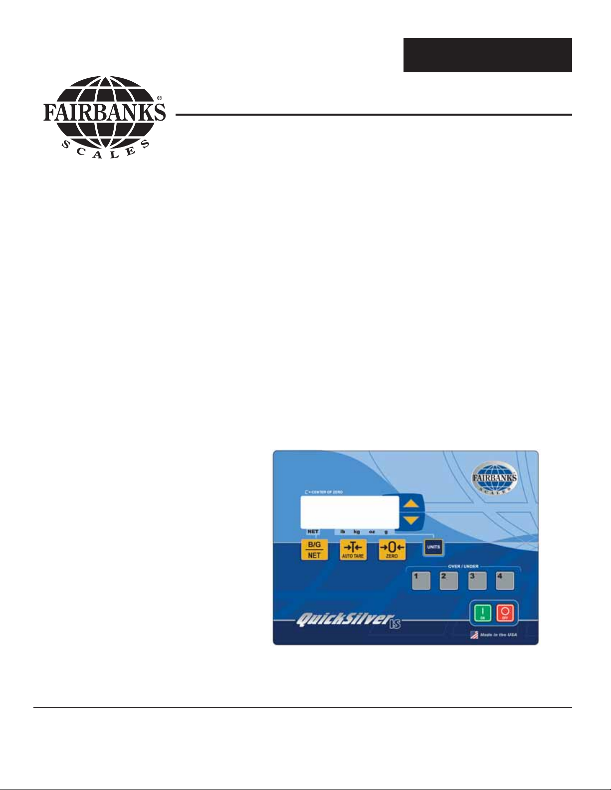
A. Keys
ON - When pressed, turns the indicator ON. The display will go through a
warm- up sequence and then go into the weigh mode.
OFF - When pressed, turns the indicator OFF.
UNITS - Switches the scale between the available units, pounds, kilograms,
ounces, and grams.
UP - DOWN - These are used to scroll through the various values in each of the
program options and are used to change the over/under values
in the checkweigh mode.
1, 2, 3, 4 - These are used to program and select the stored checkweigh values.
AUTO - Enters the value of the weight on the platform into memory as a tare
weight.
GROSS - Toggles the display between GROSS weight and NET weight.
ZERO - When pressed, sets the indicator to zero.
1
2
3
4
UNITS

B. Indicators:
NET When ON, indicates the scale is in the NET mode. When OFF, indicates
the scale is in the GROSS mode.
lb Indicates the scale is using pounds as the unit of weight.
kg Indicates the scale is using kilograms as the unit of weight.
oz Indicates the scale is using ounces as the unit of weight.
g Indicates the scale is using grams as the unit of weight.
Center-of-Zero Indicates the scale is at the zero point and is ready to
weigh.
C. Weighing
Remove any weight from the platform. If the instrument is OFF, press and hold the ON
key until the display comes on (not blank) and the indicator begins its initiation
sequence (the PROM # and Revision will be displayed briefly i.e., 11754.3). The scale
will begin operations in the Gross Weighing Mode.
The Zero function, Auto Tare function, and AZT require the displayed weight to be
stable before these functions will operate. The weight reading is stable if the variation
in weight is less than the programmed motion range. If the rate of change in weight is
less than 2.5 times the motion range every second, then the weight is stable.
1. Instrument Weighing Functions
The industry uses three terms which describe the apportionment of an object's
weight. These terms are GROSS WEIGHT, TARE WEIGHT, and NET WEIGHT.
• Gross weight is the total weight of an object. This would include any
incidental materials as well as the primary materials which comprise
the object.
• Tare weight is the weight of the incidental materials.
• Net weight is the weight of the primary materials. Tare weight and Net weight
together equal the Gross weight.
Example: A can of house paint is an object to be weighed. The can is incidental
material used to hold the primary material, paint, and the label is incidental
material used to identify the paint. All of the incidental materials taken
together make up the tare weight. All of the primary materials' weights
together make up the Net weight; in this case pigment, vehicle, and solvent.
The object is made up of incidental materials, can and label, and primary
materials, paint. Taken together, this is the gross weight.
The three weights can be expressed in terms as follows:
GROSS = NET + TARE
TARE = GROSS - NET
NET =GROSS - TARE
50770 12 04/12 Rev. 5

The equation, NET = GROSS -TARE, is particularly important because it is the
equation that a scale uses to figure net weights in NET WEIGHING MODE. The
gross weight is a function of the weight on the platform and the zero reference.
Tare weight is always an operator defined value.
a. Basic Weighing
1). Turn ON the indicator and the display will go through the warm-up
sequence.
2). When the warm-up sequence is complete, the display should show
zero and the Center-of-Zero indicator should be ON. If it is not, press
the ZERO key.
3)
. For GROSS weighing, the NET indicator should be OFF. If it is not,
press the GROSS/NET key until the NET indicator is OFF.
4)
. Place the object to be weighed on the platform. As soon as the system
is stable, the weight value will appear in the display.
b. Tare Weighing
1). Turn ON the indicator and the display will go through the warm-up
sequence.
2). When the warm-up sequence is complete, the display should show
zero and the Center-of-Zero indicator should be ON. If it is not, press
the ZERO key. Any tare weight in memory when the scale was turned
off will be lost. A new tare weight must be entered into tare memory.
3). Place the empty container that is going to be used on the platform
and press the AUTO/TARE key. The weight of the empty container
will be entered into memory as a tare weight.
4). Remove the container from the platform. The display will show a
NEGATIVE tare weight value.
5). Place the same or similar container filled with product on the platform.
The display will show the weight of the material in the container.
c. To change the TARE weight value:
1). With no weight on the platform, press the ZERO key. The display will
show zeros and the Center-of-Zero indicator will be ON.
2). Place the new container on the platform and press the AUTO/TARE
key. The old tare weight will be deleted from memory and the new
tare weight entered.
50770 13 04/12 Rev. 5

Note: In the Checkweighing Mode the ZERO, AUTO/TARE, and UNITS keys are disabled.
50770 14 04/12 Rev. 5
d. Weighing Units
To select the desired weighing units, press the UNITS key. The Units indicator
will move in response to the key.
The selected weighing units will be saved in memory each time the OFF key is
pressed. This feature allows the instrument to return to the weighing units in
use when power is restored.
The selected weighing units will not change unless:
1. The UNITS key is pressed.
2. Power to the instrument is lost prior to pressing the OFF key.
3. The Programming mode of the instrument is accessed.
e. Checkweighing
CHECKWEIGHING is a process in which a TARGET weight is entered into the
scales memory. The display shows the operator where the weight on the
platform is, over or under, relative to the target weight.
The TARGET VALUE is the weight that has been selected as the weight to be
achieved in the checkweighing process. The target value refers to the absolute
value of the Gross weight only. This is a programmable feature.
The LIMIT WEIGHT value is the amount over or under the target weight that is
to be shown in the display. This is a programmable feature.
Three different ranges can be shown in the display; the accept range, the over
range and the under range. The size of the ranges is set by the LIMIT WEIGHT
value.
When the weight on the platform is within the ACCEPT range, the display will
show a series of "- - -". A pointer will show the operator where the weight value
is, within the ACCEPT range.
If the weight on the platform is over or under the values set by the limits, the
display will show a series of "u"s for under, or up-side-down "u"s for over. A
pointer will tell the operator where in the over or under range the weight value is
located.
To exit the Checkweighing Mode, press the GROSS/NET key.

A. Ac c ept R ange Display
B. Under R ange Display
C. Over Range Display
(Target V alue -
Limit Value)
(Target V alue 2 x L imit Value)
(Target V alue +
2 x L imit Value)
(
Tar get Value -
of the Limit Value)
(
Tar get Value +
of the Limit Value)
(Target V alue +
Limit Value)
(Target V alue 3 x L imit Value)
(Target V alue +
3 x L imit Value)
Pointer
6
6
5
5
/
/
Not Used
Not Used
Not Used
Not Used
Note: Target and limit weight values - while values of 0, 1, 2, 3 , or 4 divisions may be
entered as target or limit values during the programming, the system will ALWAYS default to 5
divisions.
Note: When the arrow keys are pressed, Fine adjustment changes the last two digits,
Coarse adjustment changes the first two digits. The operator can toggle between fine and
coarse adjustments by pressing the [UNITS] key.
50770 15 04/12 Rev. 5
f. Over/Under Setup
1. Press the ZERO key and the display will show "0" with the center-of-
zero indicator ON.
2. Press the appropriate OVER/UNDER key, 1, 2, 3, or 4. The display
will flash the last target value entered into memory and then display
the OVER/UNDER graphic.
3. To change the TARGET WEIGHT, press the UP key. The display will
show the current target weight in memory as a four digit number.
4. Press the UP key to increase the target weight or the DOWN key to
decrease the target weight. In some cases, it will be faster to enter a
new target weight or limit weight by starting from 0. Press the ZERO
key. The display will be reset to all zeros. Use the arrow keys and
the UNITS key to enter a new target weight or limit weight.

50770 16 04/12 Rev. 5
5. With the appropriate TARGET weight displayed, press the same
OVER/UNDER key, 1, 2, 3, or 4 as was pressed in Step 2.
6. To change the LIMIT WEIGHT, press the DOWN key. The display will
show the current limit weight in memory as a four digit number.
7. Press the UP key to increase the limit weight or the DOWN key to
decrease the limit weight.
8. With the appropriate LIMIT weight displayed, press the same
OVER/UNDER key, 1, 2, 3, or 4 as was pressed in Step 2.
9. Repeat this process for each of the four OVER/UNDER programs.
g. Over/Under Weighing
1. Press the OVER/UNDER key, 1, 2, 3, or 4, that is to be used in the
weighing operation. The display will show the appropriate
OVER/UNDER graphic.
2. Place the item to be weighed on the platform. The indicator in the
display will move to show the weight as being UNDER, OVER, or on
TARGET.
3. Add or remove material from the platform until the indicator shows on
target.
4. Remove the material from the platform and repeat the process.
h. Exit Over/Under Weighing
To exit the Over/Under Weighing Mode, press the GROSS/NET key. The
indicator will return to the Weigh Mode.
Note: When the arrow keys are pressed, Fine adjustment changes the last two digits,
Coarse adjustment changes the first two digits. The operator can toggle between fine and
coarse adjustments by pressing the [UNITS] key.

Section 6: Battery Pack
* * WARNING! * *
Battery packs are to be charged in non-hazardous areas only!
INPUT VOLTAGES 120 VAC, 60 Hz
BATTERY OUTPUT VOLTAGES 7.0 VDC +/- 0.2 VDC at the end of charge cycle with
battery connected.
LEADS • Output leads 18 AWG, approximately three feet
(3’).
• Extended power cord up to six feet (6’).
STATUS LED Brightness sufficient to discern the charge status
under general office environment lighting.
CHARGING TIME • Sixteen (16) hours maximum for undamaged
chargeable battery (electrolyte not depleted).
• Initial unloaded output voltage of 5.0 VDC.
• Do not recharge a battery with a voltage below
4.0 VDC.
OPERATING 0°C to +38°C (+32°F to +100°F).
50770 17 04/12 Rev. 5
A. Description
Accessory 530 Battery Recharger is a Safe Area
Smart Charger, intended for non-hazardous, safe areas
only. It is only used for recharging Battery Accessory 352.
• This Accessory will fully charge a completely discharged
532 Battery within sixteen (16) hours.
• A charged battery can be left on the charger without any
resulting damage to either the charger or the battery pack.
• When a discharged Accessory 532 Battery is first
connected to a charger, the status LED on the charger will
be a constant yellow.
• Once the battery is fully charged, the LED will remain a
constant green.
IMPORTANT NOTE: Use the Accessory 530 Battery Recharger in a SAFE AREA only.
B. Specifications

C. States of Operation
STATE 1: NO BATTERY
• RED LED is constantly on.
• No battery is attached to the charger, and no current is flowing from the charger.
STATE 2: UNDER VOLTAGE BATTERY
• RED LED flashes at a set interval.
• A battery is attached to the charger, but is below the 3.6V threshold.
– The charger will attempt a trickle charge for up to sixteen (16) hours to restore the
battery to normal state.
– If at the end of sixteen (16) hours the battery has not reached 3.6V, the charger
shuts down.
– RED LED flashes with a steady YELLOW LED.
– No battery charge exists while in this state.
• The small trickle charge in this state is about 10% duty cycle, or about 60mA*.
STATE 3: CHARGING
• YELLOW LED is on constantly.
• Indicates the battery is between 3.6V and 7.0V.
• Charger will continue charging for up to sixteen (16) hours
– If charger has not reach next state in the sixteen (16) hours, it will determine voltage
▪ If charger is between 6.4V and 7.2V, the unit switches to State 4: Trickle Charge.
▪ If charger is not to 6.4V, charger shuts down and shows YELLOW LED on steady with
– RED LED flashing (used to indicate possible fault with battery).
• Full charge is produced in this state is 200mA*.
STATE 4: TRICKLE CHARGE
• GREEN LED will be on steady, battery pack is considered fully charged
• Indicates the battery has reached 7.0V, and is now between 6.6V and 7.2V.
– Hysteresis is built in to allow battery’s chemicals to settle.
• Charger will stay in this state indefinitely as long as battery voltage remains between
6.6V and 7.2V.
– If voltage drops below 6.6V, the charger returns to State 3: Charging.
– If voltage rises above 7.2V, the charger switches to State 5: Over Voltage.
• Trickle charge is produced at about 35% duty cycle or about 60mA*.
STATE 5: OVER VOLTAGE
• GREEN LED will be on steady with the RED LED flashing.
• This indicates the battery has been over charged above 7.2V.
– Current from the charger is stopped and charger waits for voltage level to drop back
below 7.2V.
• No current is produced
* Current levels will vary between batteries and is only given as a reference.
50770 18 04/12 Rev. 5

50770 19 04/12 Rev. 5
Appendix I: FM CONTROL DRAWINGS

50770 20 04/12 Rev. 5

50770 21 04/12 Rev. 5

50770 22 04/12 Rev. 5

50770 23 04/12 Rev. 5

50770 24 04/12 Rev. 5

50770 25 04/12 Rev. 5
 Loading...