

Page 1
Service / Installation Manual
5000 Series
Bench Scale Platforms
51245
© 2010-2013 by Fairbanks Scales, Inc.
All rights reserved
Revision 3 07/13
Page 2

Page 3

Amendment Record
5000 SERIES
BENCH SCALE PLATFORMS
SERVICE / INSTALLATION MANUAL
Document 51245
Manufactured by Fairbanks Scales, Inc.
821 Locust
Kansas City, Missouri 64106
Created 06/10 Created document
Revision 1 06/10 Document release
Revision 2 02/13 Corrected model numbers included.
Revision 3 07/13 Corrected formatting errors and added part number 14964.
Page 4

Disclaimer
Every effort has been made to provide complete and accurate information in this manual. However,
although this manual may include a specifically identified warranty notice for the product, Fairbanks
Scales makes no representations or warranties with respect to the contents of this manual, and
reserves the right to make changes to this manual without notice when and as improvements are
made.
Fairbanks Scales shall not be liable for any loss, damage, cost of repairs, incidental or consequential
damages of any kind, whether or not based on express or implied warranty, contract, negligence, or
strict liability arising in connection with the design, development, installation, or use of the scale.
© Copyright 2010-2013
This document contains proprietary information protected by copyright. All rights are reserved; no part
of this manual may be reproduced, copied, translated or transmitted in any form or by any means
without prior written permission of the manufacturer.
07/13 4 51245 Rev. 3
Page 5

Table of Contents
SECTION 1: INTRODUCTION & DESCRIPTION . . . . . . . . . . . . . . . . . . . . . . . 6
SECTION 2: TECHNICAL SPECIFICATIONS . . . . . . . . . . . . . . . . . . . . . . . . . 7
SECTION 3: INSTALLATION . . . . . . . . . . . . . . . . . . . . . . . . . . . . . . . . . . . . . 8
SECTION 4: PARTS REPLACEMENT . . . . . . . . . . . . . . . . . . . . . . . . . . . . . . 9
SECTION 5: 10” X 10” PLATFORMS . . . . . . . . . . . . . . . . . . . . . . . . . . . . . . 10
SECTION 6: 12” X 12” PLATFORMS . . . . . . . . . . . . . . . . . . . . . . . . . . . . . . 12
SECTION 7: 18” X 18” PLATFORMS . . . . . . . . . . . . . . . . . . . . . . . . . . . . . . 14
SECTION 8: 18” X 24” PLATFORMS . . . . . . . . . . . . . . . . . . . . . . . . . . . . . . 16
SECTION 9: 24” X 24” PLATFORMS . . . . . . . . . . . . . . . . . . . . . . . . . . . . . . 18
SECTION 10: TROUBLESHOOTING FLOW CHART . . . . . . . . . . . . . . . . . . . 20
07/13 5 51245 Rev. 3
Page 6
Section 1: Introduction & Description
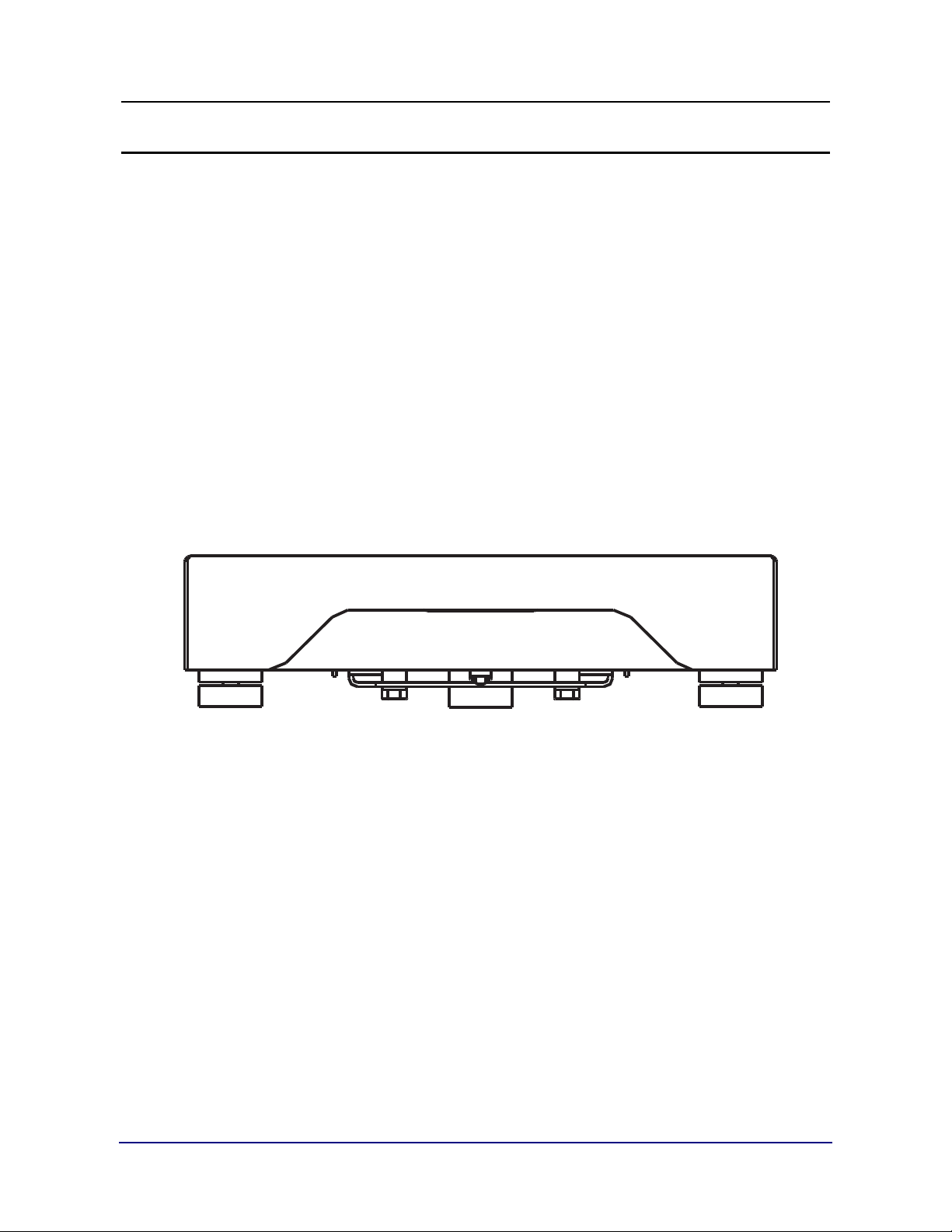
The 5000 Series analog platforms are constructed of stainless steel. There is a wide
variety of application uses. These bench scales are designed for pharmaceutical,
chemical, and food applications because of their ruggedness and easy-to-clean
construction.
Certifications include:
• NTEP CC: 94-100
• MC: AM5107, AM5279, and AM5573
07/13 6 51245 Rev. 3
Page 7

Section 2: Technical Specifications
Division size
lb oz kg g
2 x .0005 32 x .01 .91 x .002 910 x .2
5 x .001 80 x .02 2.26 x .0005 2260 x .5
6 x .002 96 x .05 2.72 x .001 2720 x 1
10 x .002 160 x .05 4.53 x .001 4530 x 1
12 x .005 192 x .1 5.44 x .002 5440 x 2
24 x .01 384 x .2 10.9 x .005 10900 x 5
25 x .005 400 x .1 11.3 x .002 11300 x 2
30 x .01 480 x .2 13.6 x .005 13600 x 5
40 x .01 640 x .2 18.1 x .005 18100 x 5
50 x .01 800 x .2 22.6 x .005 22600 x 5
60 x .02 960 x .5 27.2 x .01 27200 x 10
80 x .02 280 x .5 36.2 x .01 36200 x 10
100 x .02 1600 x .5 45.4 x .01 45400 x 10
120 x .02 1920 x .5 54.4 x .01 54400 x 20
150 x .05 2400 x 1 68 x .02 68000 x 20
200 x .05 3200 x 1 90.7 x .02 90700 x 20
250 x .05 4000 x 1 113 x .02 113000 x 50
300 x .1 4800 x 2 36 x .05 136000 x 50
500 x .1 8000 x 2 227 x .05 227000 x 50
1000 x .2 16000 x 5 454 x .1 454000 x 100
07/13 7 51245 Rev. 3
Page 8

Section 3: Installation
The platforms are shipped ready to interface to an analog instrument. Refer to the
table below for wiring color codes.
1. Place the platform where it will be used.
2. Level the platform using the feet.
3. Connect the interface cable to the instrument. The load cell interface cable is
Platform wiring
identified as follows.
Product
Number
24760
through
24769
and
26029
24862
through
24864
24783
through
24786
24770
through
24776
+
Excitation
--
Excitation
+
Sense
--
Sense
+
Signal
--
Signal
Green Black N/A N/A White Red
Green Black N/A N/A White Red
Green Black N/A N/A White Red
Green Black Blue Brown
Red White
07/13 8 51245 Rev. 3
Page 9

Section 4: Parts Replacement
Load cell replacement
Tools required:
• Open-end wrench
• Side cutter
• Torque wrench
Procedure:
1. Disconnect the instrument from the power supply.
2. Place the platform upright without the cover.
3. Remove the screws holding the load cell and spacer in place.
4. Remove the load cell and cable, and note the cell and cable placement!
5. Install the new load cell and the spacer(s).
6. Tighten the load cell mounting screws to 8 (± 2) INCH/LBS of torque only.
7. Route the load cell cable exactly as the original cable and plug in the connector.
8. Calibrate the instrument.
07/13 9 51245 Rev. 3
Page 10

Section 5: Parts - 10” x 10” Platforms
10” X 10” Platform (2 lb., 6 lb., and 25 lb. capacities)
Item Part No. Description
2 14961 Load cell – 7 kg – for platforms 24760, 24761, and 24762
2 14963 Load cell – 30 kg – for platform 24763
4 14219 Foot assembly (used as a bumper)
5 23664 Spider, platform
6 23669 Cover, platform
7 24779 Shim, load cell (.109 thick)
10 23668 Base, platform
11 24406 Clip, ground
13 11051 Screw, machine, hex head cap, .23 – 20 x .75
16 24408 Screw, set, socket head, cup point, 10 – 32 x .50
17 11103 Nut, hex, 10 – 32
18 11920 Adhesive, screw
19 17613 Tie wire
20 14220 Foot assembly
21 11039 Bull’s eye level
22 13223 Adhesive sealant
24 22963 Nut, nylon, stop
Diagram on next page.
07/13 10 51245 Rev. 3
Page 11

W
OUTPUTLC (+)SIG
SHIELD
LC (-)SIG
LC SHIELD
Y
R
OUTPUT
INPUTLC (+)EX
LC (-)EX
G
BK
INPUT
10
20
24
22
16 17
2
21
1813
11
13 18
7
6
4
7
5
19
(.205)
51245-1
PARTS DIAGRAM – 10” X 10” PLATFORM
07/13 11 51245 Rev. 3
Page 12

Section 6: Parts - 12” x 12” Platforms
12” x 12” Platform (30 lb, 50 lb, and 100 lb capacities)
Item Part No. Description
2 14963 Load cell – 30 kg – for platform 24763, 24764, 24765
2 14964 Load cell – 60 kg – for platform 26029.
4 14219 Foot assembly (used as a bumper)
5 23971 Spider, platform
6 23977 Cover, platform
7 24780 Shim, load cell (.185 thick)
10 23976 Base, platform
11 24406 Clip, ground
13 11051 Screw, machine, hex head cap, .23 – 20 x .75
16 24408 Screw, set, socket head, cup point, 10 – 32 x .50
17 11103 Nut, hex, 10 – 32
18 11920 Adhesive, screw
19 17613 Tie wire
20 14220 Foot assembly (used as a bumper)
21 11039 Bull’s eye level
22 13223 Adhesive sealant
24 22963 Nut, nylon, stop
Diagram on next page.
07/13 12 51245 Rev. 3
Page 13

20
24
16 17
2
10
7
11
6
5
4
13 18
13 182122
7
19
(.357)
51245-2
W
OUTPUTLC (+)SIG
SHIELD
LC (-)SIG
LC SHIELD
Y
R
OUTPUT
INPUTLC (+)EX
LC (-)EX
G
BK
INPUT
PARTS DIAGRAM – 12” X 12” PLATFORM
07/13 13 51245 Rev. 3
Page 14

Section 7: Parts - 18” x 18” Platforms
18” x 18” Platform (50 lb., 100 lb., 150 lb., and 300 lb. capacities)
Item Part No. Description
2 14965 Load cell – 100 kg – for platforms 24766, 24767 and 24768
2 14966 Load cell – 150 kg – for platform 24769
4 14219 Foot assembly (used as a bumper)
5 23538 Spider, platform
6 23548 Cover, platform
8 24843 Shim, load cell (.750 thick) for platform 24769
9 24781 Shim, load cell (.500 thick)
10 23547 Base, platform
11 24406 Clip, ground
12 24844 Screw, machine, hex head cap, ⅜ – 16 x 1.50 for platform 24769
13 11047 Screw, machine, hex head cap, ⅜ – 16 x 1.25
16 24782 Screw, set, socket head, cup point, ¼ – 20 x .88
17 11131 Nut, hex, jam, ¼ – 20
18 11920 Adhesive, screw
19 17613 Tie wire
20 14220 Foot assembly
24 22963 Nut, nylon, stop
34 11039 Bull’s eye level
35 13223 Adhesive sealant
Diagram on next page.
07/13 14 51245 Rev. 3
Page 15

34
35
13
18
20
4
2
5
1716
6
24
10
13
18
9
9
19
24766 50 LB. CAPACITY
24767 100 LB. CAPACITY
24768 150 LB. CAPACITY
24769 300 LB. CAPACITY
1716
13
35
2
34
18
9
10
6
8
12
18
11
5
20
24
19
4
11
LC (+)SIG
LC SHIELD
LC (-)SIG
R
Y
SHIELD
OUTPUT
BK
LC (+)EX
LC (-)EX
G
W
OUTPUT
INPUT
INPUT
(.580)
(.830)
W
BK
R
Y
LC SHIELD
LC (-)EX
LC (+)SIG
LC (-)SIG
LC (+)EX
G
SHIELD
OUTPUT
OUTPUT
INPUT
INPUT
51245-3
PARTS DIAGRAM – 18” X 18” PLATFORM
07/13 15 51245 Rev. 3
Page 16

Section 8: Parts - 18” x 24” Platforms
18” x 24” Platform (50 lb., 100 lb., and 300 lb. capacities)
Item Part no. Description
2 15835 Load cell - 150 kg – for platforms 24770, 24771 & 24772
2 21350
4 14219 Foot assembly (used as a bumper)
5 24430 Spider, platform
6 24429 Cover, platform
9 15831 Spacer, load cell (.250 thick)
10 24428 Base, platform
11 24406 Clip, ground
13 11050 Screw, machine, hex head cap, 5/16 - 18 x 1.00
18 11920 Adhesive, screw
19 17613 Tie wire
20 14220 Foot assembly
24 22963 Nut, nylon, stop
34 11039 Bull’s eye level
35 13223 Adhesive sealant
Load cell (hermetically sealed) - 100 kg – for platforms 24862, 24863 & 24864)
Diagram on next page.
07/13 16 51245 Rev. 3
Page 17

13
18
11
2
10
13
18
9
24
19
20
35
34
4
9
6
5
(.800)
24770, 24771, AND 24772
SHIELD
(+)
(-)
(-) EX
(+) SIG
(-) SIG
(+) EX
SENSE
SENSE
INPUT
OUTPUT
OUTPUT
INPUT
BL
BR
BK
R
W
G
24862, 24863, AND 24864
(+) SIG
(-) EX
(-) SIG
SHIELD
(+) EX
OUTPUT
INPUT
OUTPUT
INPUT
W
BK
R
Y
G
51245-4
PARTS DIAGRAM – 18” X 24” PLATFORM
07/13 17 51245 Rev. 3
Page 18

Section 9: Parts - 24” x 24” Platforms
24” x 24” Platform (50 lb, 100 lb, and 300 lb capacities)
Item Part no. Description
1 24447 Base, platform
3 21350 Load cell (hermetically sealed) - 100 kg (24783 and 24784)
3 15835 Load cell - 150 kg (24773 and 24774)
3 21353 Load cell (hermetically sealed) - 500 kg (24785)
3 15836 Load cell - 300 kg (24775)
3 15837 Load cell - 500 kg (24776)
3 21353 Load cell (hermetically sealed) - 500 kg (24786)
4 15831 Spacer, load cell (.250 thick)
7 15827 Plate support (24773, 24774, 24783 and 24784)
7 15828 Plate support (24775, 24776, 24785 and 24786)
8 15826 Spider, platform
9 24448 Cover, platform
12 11480 Foot assembly
13 11101 Nut, hex, ½ - 13
15 11060 Screw, machine, hex head cap, ¼ - 20 x .50
16 11049 Screw, machine, hex head cap, 5/16 - 18 x 1.25
17 11050 Screw, mach. hex hd cap 5/16 - 18 x 1.00 (24773, 24774, 24783 & 24784)
19 11920 Adhesive, screw
24 17613 Tie wire
30 15017 Clip, ground
34 11039 Bull’s eye level
35 13223 Adhesive sealant
Diagram on next page.
07/13 18 51245 Rev. 3
Page 19

WIRING FOR 24773, 24774, 24775 & 24776
WIRING FOR 24783, 24784, 24785, AND 24786
(-) EX
(-) SIG
(+) SIG
(+) EX
SHIELD
SHIELD
(+)
(+) EX
(-)
(-) EX
(+)
(-) SIG
VIEW A - SHOWN WITH COVER REMOVED
1
8
3534
24773, 24783 ASSY, 100 LB. CAPACITY
24774, 24784 ASSY, 250 LB. CAPACITY
1915
1915
1915
1916
13
30
7
19
9
8
4
24
4
3
17
12
1
INPUT
OUTPUT
OUTPUT
INPUT
BK
R
W
G
Y
SENSE
INPUT
SENSE
INPUT
OUTPUT
OUTPUT
BL
G
BR
BK
R
W
51245-5
PARTS DIAGRAM – 24” X 24” PLATFORM
07/13 19 51245 Rev. 3
Page 20

Scale
not
working
Perform a visual inspection and
begin asking specific questions
to identify the cause and/or
symptoms BASICS
Place instrument
on simulator
Does it work?
Repair the
instrument
Check wiring at load cell,
perform load cell tests,
and/or replace load cell
Problem resolved;
finalize all repairs
Does it work?
YES
NO
YES
NO
Call
Technical
Support
51245-6
Section 10: Troubleshooting Flow Chart
07/13 20 51245 Rev. 3
Page 21

Page 22

5000 Series Platforms
SERVICE/INSTALLATION MANUAL
Manufactured by Fairbanks Scales, Inc
821 Locust St.
Kansas City, MO 64106
www.fairbanks.com
.
DOCUMENT 51245
 Loading...