

Page 1
Operator Manual
2800 Series
Intrinsically Safe Instrument
with Intalogix
™
Technology
50647
© 2001-2012 by Fairbanks Scales, Inc. Revision 9 01/12
All rights reserved
Page 2

Page 3

2800 Series
Intrinsically Safe Instrument
With Intalogix™ Technology
Document 50647
Manufactured by Fairbanks Scales Inc.
821 Locust
Kansas City, Missouri 64106
AMENDMENT RECORD
Issue #1 09/01 Created and released manual.
Issue #2 11/01 Updated specifications.
Issue #3 03/02 Updated specifications and procedures
Issue #4 08/02 Updated specifications for 4-20mA
Issue #5 01/03 Updated drawings, note, and caution graphics.
Issue #6 11/06 Updated specifications for 4-20mA.
Revision 7 10/07 Updated format, images, and technical specifications.
Revision 8 07/09 Updated Control Drawings, formatting, added down
weighing information
Revision 9 01/12 Updated Battery Charger revision information and FM
Control Drawings in Appendix II.
01/12 3 50647 Rev. 9
Page 4

Disclaimer
Every effort has been made to provide complete and accurate information in this manual. However,
although this manual may include a specifically identified warranty notice for the product, Fairbanks
Scales makes no representations or warranties with respect to the contents of this manual, and
reserves the right to make changes to this manual without notice when and as improvements are
made.
It is the responsibility of the requesting party to develop, maintain, install, and connect networking
devices and general network connectivity as it applies to the originating party’s network. No warranty
or guarantee, expressed or implied, concerning the network, its design, its installation, or operational
characteristics has been offered by Fairbanks Scales. Fairbanks Scales shall not be liable for any
loss, damage, cost of repairs, incidental or consequential damages of any kind, whether or not based
on express or implied warranty, contract, negligence, or strict liability arising in connection with the
design, development, installation, or use of an intended network.
© Copyright 2001-2012
This document contains proprietary information protected by copyright. All rights are reserved; no part
of this manual may be reproduced, copied, translated or transmitted in any form or by any means
without prior written permission of the manufacturer.
01/12 4 50647 Rev. 9
Page 5

Table of Contents
SECTION 1: GENERAL INFORMATION .................................................................. 7
1.1. Description ................................................................................................................... 7
1.2. Specifications .............................................................................................................. 8
1.3. Accessories ................................................................................................................. 9
1.3.1. Accessory 2802 Intrinsically Safe Controller ....................................................................... 9
1.3.2. Accessory 2825 Safe Area Power Supply ........................................................................... 9
1.3.3. Accessory 2830 Battery (20615) ......................................................................................... 9
1.3.4. Battery Charging ................................................................................................................ 11
1.3.5. Accessory 2845 Battery Charger 110-120 VAC (31354) .................................................. 11
1.3.6. Accessory 2841 Battery Charger 230VAC for Accessory 2830 (21740) ........................... 11
1.3.7. Accessory 2850 Safe Area Relay Setpoint Interface (20570) ........................................... 12
1.3.8. Accessory 2860 Safe Area Data Converter (20523) ......................................................... 13
1.3.9. Accessory 2875 Intrinsically Safe Interconnection Cable (21737) .................................... 13
1.3.10. Accessory 2880 Analog Cell Input (19797) ..................................................................... 14
1.3.11. Accessory 2900 Splice Box (20310) ................................................................................ 14
1.3.12. Accessory 2910 Splice Box Kit w/cables (20199) ........................................................... 14
1.3.13. Accessory 5806 Fiber Optic cable (17229) ..................................................................... 14
1.4. Typical System Layout #1 ......................................................................................... 15
1.5. Typical System Layout #2 ......................................................................................... 16
SECTION 2: OPERATION ........................................................................................ 17
2.1. Customer/ Owner Responsibilities............................................................................. 17
2.2. Safety ........................................................................................................................ 18
2.3. Front Panel Key Functions ........................................................................................ 19
2.3.1. LEGENDS .......................................................................................................................... 22
2.3.2. Instrument Weighing Functions ......................................................................................... 23
2.3.3. Gross Weighing ........................................................................................................ ......... 25
2.3.4. Tare Weights ..................................................................................................................... 25
SECTION 3: PROGRAMMING ................................................................................. 30
3.1. Menu Navigation ........................................................................................................ 30
3.2. tArgEt MENU Description .......................................................................................... 32
3.3. inFo Menu Description ............................................................................................... 33
3.4. Main Menu Descriptions ............................................................................................ 34
3.5. I/O Menu .................................................................................................................... 35
3.5.1. I/O Menu Descriptions ....................................................................................................... 36
SECTION 4: SECURITY ........................................................................................... 48
4.1. Security Codes .......................................................................................................... 48
01/12 5 50647 Rev. 9
Page 6

Table of Contents
APPENDIX I: TROUBLESHOOTING/ERROR CODES ............................................ 49
APPENDIX II: FM CONTROL DRAWINGS .............................................................. 50
APPENDIX III: MATERIAL SAFETY DATA SHEET ................................................ 62
APPENDIX IV: CONTINUOUS OUTPUT DATA STREAMS .................................... 64
A. Format: Fairbanks Computer (FbPutr) ......................................................................... 64
A.2. Status Word B ...................................................................................................................... 65
A.3. Status Word C ...................................................................................................................... 65
B. 4. Format : Consolidated Controls (ConCon) .............................................................. 66
C. Format: Weightronix (tronix) ....................................................................................... 67
APPENDIX V: DEMAND OUTPUT DATA STREAMS ............................................. 68
A. Format : Computer Polled (Poll) ................................................................................... 68
B. Format: Computer Polled with Id (Pollid)...................................................................... 69
APPENDIX VI: ACC 2860 COMMUNICATION WIRING .......................................... 70
A. Port A ........................................................................................................................... 70
B. Port B ........................................................................................................................... 71
APPENDIX VII: ASCII CODES ................................................................................. 72
01/12 6 50647 Rev. 9
Page 7

Section 1: General Information
1.1. DESCRIPTION
The model 2800 series is an Intrinsically Safe instrument utilizing Intalogix™
Technology. It is Factory Mutual (FM) Approved for direct use in hazardous
environments as shown in the FM Approved Control Drawings.
The 2800 series instrument eliminates the need for explosion proof enclosures or
purging systems. Enclosed in a stainless steel, NEMA 4X enclosure, the
instrument is able to withstand both wash down and corrosive environments.
Major features of the Instrument include push-button programming and calibration,
with data storage in nonvolatile ROM for 100% memory retention.
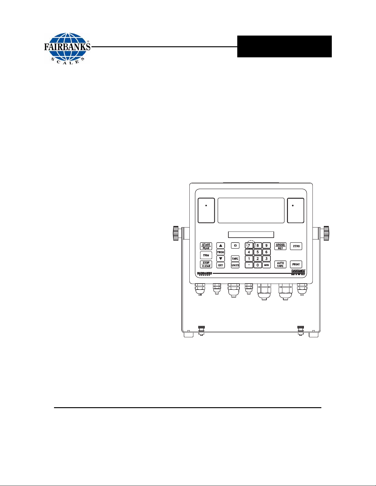
The 2800 series instrument features a large 1.25 inch high LCD weight display
with an additional alphanumeric status display, which can be tilted up or down to
accommodate different lighting conditions. Its microprocessor controlled design
allows the instrument to be rapidly programmed at installation to meet the specific
requirements of the application.
The obtainable accuracy meets Handbook 44 requirements, and the instrument is
approved for commercial application up to 10,000 divisions. A maximum of
30,000 divisions can be achieved for non-commercial applications.
This ultra-low power instrument can interface to analog load cells through an
Intalogix™ intrinsically safe controller or can be connected directly to analog load
cells using an available optional accessory.
The instrument provides fiber optic interfaces from the hazardous area to the
optional accessories located in a safe area. The optional accessories provide
communications to various types of peripheral devices in selectable formats for
RS232, and 20mA data outputs. Other available options include analog interfaces
through programmable setpoints and 4-20 ma analog outputs. The instrument may
be powered by a battery or a continuous power accessory.
01/12 7 50647 Rev. 9
Page 8

1.2. SPECIFICATIONS
Section 1: General Information
Instrument Approvals
FM Approvals
NTEP: CoC 01-009
CWM: Pending
Class I, II, and III
Division 1
Groups A, B, C, D, E, F, and G
* For more detailed information, see FM Control Drawing 21943.
Appendix II.
see
Physical Dimensions Approximately 13"W x 9"H x 3"D
Material Stainless Steel
Enclosure Rating
Capacities Service programmable up to 999,950 lb, kg, oz, g, tons, lb-oz, or gallons
Division Sizes
Resolution
Sensitivity
Load Cells Up to 16 - 350 or 1000 ohm impedance
Load Cell Cable
Length/Wire Gauge
NEMA 4X
IP65
Service programmable for .0002 to 50
Fixed at one (1) oz. in the lb/oz mode
Commercial - Up to 10,000 divisions maximum
Noncommercial - Up to 30,000 divisions maximum
1µv/d (microvolt/division)
75' maximum
20 AWG maximum
Display Weight Display
1.25" height
7 segment LCD
Status Display
.38" x 3.73" Alphanumeric LCD
16 characters - .38" x .191" character size
Zero Range Service programmable - Disabled, 2, or 100%
Auto-Zero-Tracking Service programmable - Disabled, .5, 1, or 3 divisions
Motion Detection Service programmable - Disabled, .5, 1, or 3 divisions
Digital Filter Service programmable from disabled up to heavy
Display Update Rate Service programmable settings from .1 to .8 seconds.
Environment
Chemical Resistance Resistant to all petroleum derivatives and salts.
Handbook 44 Compliance Tested Operating Environment
Temp -10°C to + 40°C (+14°F to + 104°F)
Storage
Temp -40°C to + 60°C (-40°F to + 140°F)
01/12 8 50647 Rev. 9
Page 9

1.3. ACCESSORIES
1.3.1. ACCESSORY 2802 INTRINSICALLY SAFE CONTROLLER
(22119)
Each controller allows up to four (4) load cells to be interconnected
Communicates to the Model 2800 Series Instrument using Intalogix ™
Technology
Enclosure: NEMA 4X, Stainless steel
1.3.2. ACCESSORY 2825 SAFE AREA POWER SUPPLY (18448)
This accessory will provide continuous power to the Model 2800 Instrument.
The Accessory 2830 cannot be used with this accessory, as this accessory is
installed in a non-hazardous, safe area only.
Section 1: General Information
Enclosure: NEMA 4, Fiberglass
Output: 7 VDC
1.3.3. ACCESSORY 2830 BATTERY (20615)
Supplies battery power to the Model 2800 Series Instrument.
It must be recharged in a non-hazardous, safe area using Accessory 2845 or
2846 only.
Accessory 2830 is the only battery approved to be used with the
Model 2800 Series Instruments for all applications.
CAUTION
Battery surface gets very HOT during recharging!
DO NOT USE Accessory 2830
in conjunction with Accessory 2825.
01/12 9 50647 Rev. 9
Page 10

Section 1: General Information
1.3. ACCESSORIES, CONTINUED
1.3.4. BATTERY CHARGING
Charging time is 16 hours for a fully discharged battery.
The battery requires recharging when the Recharge display appears.
The battery may be recharged 100 - 500 times dependent on depth of
discharge.
Recharge intervals may vary depending upon usage.
Table 1 – Recharge intervals using Accessory 2802
RECHARGING HOURS
No. of Cells 350 ohm Load Cells 1000 ohm Load Cells
16 6 20
12 20 40
8 45 70
4 100 133
Table 2 – Recharge intervals using Accessory 2830
RECHARGING HOURS
No. of Cells 350 ohm Load Cells 1000 ohm Load Cells
16 85 133
14 90 150
12 95 172
10 100 184
8 117 199
6 133 219
4 175 247
3 194 266
1 269 320
01/12 10 50647 Rev. 9
Page 11

Section 1: General Information
1.3. ACCESSORIES, CONTINUED
1.3.5. Accessory 2845 Battery Charger 110-120 VAC (31354)
(REPLACES ACCESSORY 2840 – 21199)
The Safe Area Smart Recharger uses the Battery Accessory 2830 only.
The 2845 Battery Charger is plugged into a standard outlet.
This accessory is intended for non-hazardous, safe areas only.
Follow these guidelines when charging Battery Accessory 2830.
A charged battery can be left on the charger with no resulting damage to
either the charger or battery pack.
When a discharged battery is first connected to a charger, the status L.E.D. on
the charger will be a constant yellow as it charges.
Once the battery is fully charged, the LED remains a constant green.
CAUTION
Battery surfaces get very HOT during recharging.
1.3.6. ACCESSORY 2846 BATTERY CHARGER 230VAC (31466)
FOR ACCESSORY 2830
Equipped with a European Style 230 VAC plug.
Used with the Battery Accessory 2830 only.
Intended for non-hazardous, safe areas only.
Follow these guidelines when charging Battery Accessory 2830.
A charged battery can be left on the charger with no resulting damage
to either the charger or battery pack.
When a discharged battery is first connected to a charger, the status
L.E.D. on the charger will be a constant yellow as it charges.
Once the battery is fully charged, the LED remains a constant green.
01/12 11 50647 Rev. 9
Page 12
Section 1: General Information
1.3. ACCESSORIES, CONTINUED
1.3.6. ACCESSORY 2846 BATTERY CHARGER 230VAC (31466)
FOR ACCESSORY 2830, CONTINUED
The following chart outlines basic information for both models of battery chargers.
INPUT VOLTAGE
BATTERY OUTPUT
VOLTAGE
LEADS
STATUS L.E.D.
CHARGING TIME
OPERATING
TEMPERATURE RANGE
2845 – 120 VAC, 60 Hz – Standard style plug
2846 – 230 VAC, 50/60 Hz
7.0 VDC +/- 0.2 VDC at the end of charge cycle with battery
connected.
Output leads 18 AWG, approximately three feet (3’).
Extended power cord up to six feet (6’).
Brightness sufficient to discern the charge status under general
office environment lighting.
Sixteen (16) hours maximum for undamaged chargeable battery
(electrolyte not depleted).
Initial unloaded output voltage of 5.0 VDC.
Do not recharge a battery with a voltage below 4.0 VDC.
0°C to +38°C (+32°F to +100°F).
CAUTION
Battery surfaces get very HOT during recharging.
1.3.7. ACCESSORY 2850 SAFE AREA RELAY SETPOINT
INTERFACE (20570)
The setpoint accessory is service programmable for up to eight (8) setpoints.
These setpoints may be configured to one of five different modes of operation.
Enclosure: NEMA 4. Fiberglass
01/12 12 50647 Rev. 9
Page 13

1.3. ACCESSORIES, CONTINUED
1.3.8. ACCESSORY 2860 SAFE AREA DATA CONVERTER
(20523)
This accessory is service programmable and configurable for RS232 or 20mA
data outputs.
This accessory can also be configured to provide a 4-20 ma analog output.
Enclosure: NEMA 4; Fiberglass
4 -20 ma Specifications: 16 bit resolution (+/- .01 integral linearity)
CAUTION
The 4-20ma accessory is a passive device!
Section 1: General Information
The power is to be supplied by others, and MUST
BE
a DEDICATED and an ISOLATEDpower supply.
Current loop voltage compliance: 7vdc minimum to 40vdc maximum (typical
voltage = 24vdc)
Full scale settling time: 8msecs
Output impedance: 25 meg
Alarm current: 3.5 to 24 mA (underload/overload conditions)
─ Offset @ 25 degrees C; +/- .1% of full scale
Offset drift: +/- 25ppm of full scale per degree C
Total output error: 20mA @ 25 degrees C: +/- .2% of full scale max
Total output drift: +/- 50ppm of full scale per degree C-max
1.3.9. ACCESSORY 2875 INTRINSICALLY SAFE
INTERCONNECTION CABLE (21737)
This is the only approved cable for interconnecting the Accessory 2802, and
for connecting to the Model 2800 to the Accessory 2850.
Specifications: 2 pair - 16AWG; 0.48" O.D.
01/12 13 50647 Rev. 9
Page 14

1.3. ACCESSORIES, CONTINUED
1.3.10. ACCESSORY 2880 ANALOG CELL INPUT (19797)
This accessory allows for direct interface to a analog load cell(s).
This accessory is complete, and is supplied with mounting hardware and an
EPROM.
1.3.11. ACCESSORY 2900 SPLICE BOX (20310)
Enclosure: NEMA 4X; Stainless steel
1.3.12. ACCESSORY 2910 SPLICE BOX KIT W/CABLES (20199)
Enclosure: NEMA 4X; Stainless steel
Section 1: General Information
1.3.13. ACCESSORY 5806 FIBER OPTIC CABLE (17229)
This accessory allows a direct connection of the Model 2800 Series
Instrument.
It is located in the hazardous area to the Accessories 2850 and 2860, in the non-
hazardous, safe area for I/O operation. Maximum fiber optic cable distance is 200
feet. Do not place the fiber optic cable within conduits.
01/12 14 50647 Rev. 9
Page 15
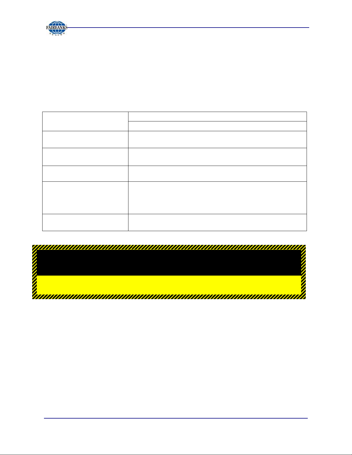
1.4. TYPICAL SYSTEM LAYOUT #1
Section 1: General Information
SEE CONTROL DRAWINGS
01/12 15 50647 Rev. 9
Page 16
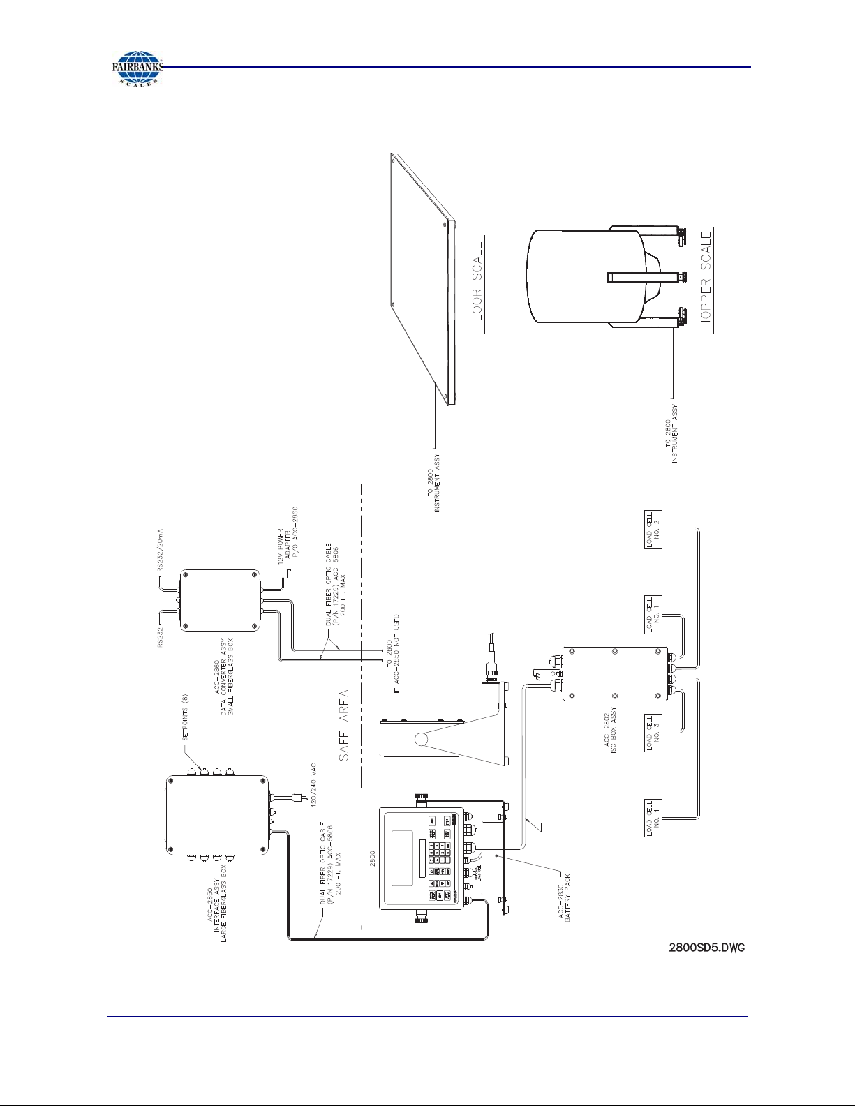
1.5. TYPICAL SYSTEM LAYOUT #2
Section 1: General Information
01/12 16 50647 Rev. 9
Page 17
Section 2: OPERATION
2.1. CUSTOMER/ OWNER RESPONSIBILITIES
It is the customer/ owners' responsibility to maintain, the platform,
instrument, and peripheral accessories in good order, and to
protect the equipment from accidental or malicious damage.
The installation shall be in accord with the manufacturer's instructions and with the
National Electric Code (ANSI-NFPA 70).
─ Refer to ANSI/ ISA-RP12.6, Installation of Intrinsically Safe Systems for
Hazardous (Classified) Locations for guidance on the installation of
intrinsically safe apparatus and systems.
Please follow these guidelines .
Do not break the seals on the instrument or attempt any internal
adjustments.
Absolutely no physical, electrical, or program modifications other than the
selection of standard options and accessories are to be made to this
equipment.
Electrical connections other than those specified may not be performed,
and no physical alterations (mounting holes and etc.)
are allowed.
No service, repairs, or adjustments, other than those
outlined in this manual, may be performed by untrained
service personnel.
01/12 17 50647 Rev. 9
Page 18

Section 2: Operation
2.2. SAFETY
As is in the case with any material handling equipment, certain safety precautions
must be observed during operation.
Never load the scale platform beyond its rated capacity.
─ Refer to the rating on the serial number plate to be certain.
Ensure that any structure which supports the platform is capable
of withstanding the weight of the platform plus its rated capacity
load.
Do not load the scale platform if there is any evidence of damage
to the platform or supporting structure.
Use safety chains or other suitable restraining devices if there is
any possibility of the load shifting, falling, or rolling from its
position on the load receiver.
01/12 18 50647 Rev. 9
Page 19
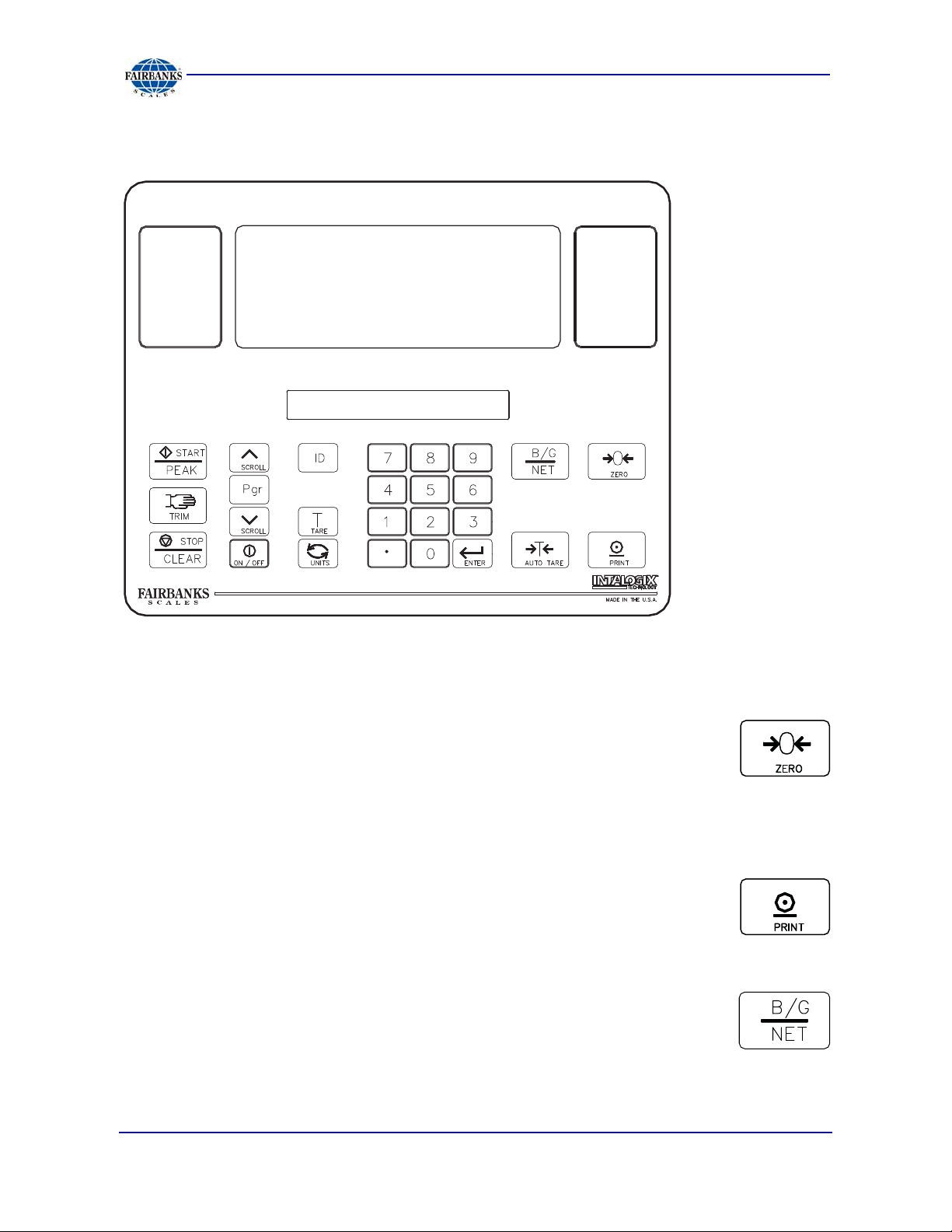
2.3. FRONT PANEL KEY FUNCTIONS
Section 2: Operation
The function of the front panel keys varies depending on the mode in which the
instrument is operated. This Subsection defines the operation of each front panel key
when in the weighing mode.
ZERO KEY
When in the Gross mode, this key sets the Gross Weight to Zero.
─ If motion exists, the ZERO command will not be executed.
─ If the weight on the platform exceeds the zero limit, and the
pressed, the Zero command will not be executed.
ZERO key is
PRINT KEY
Used to transmit weight data to an external device.
GROSS/NET KEY
Toggles between the Gross and Net Weight modes.
─ It is also used to exit programming.
01/12 19 50647 Rev. 9
Page 20
Section 2: Operation
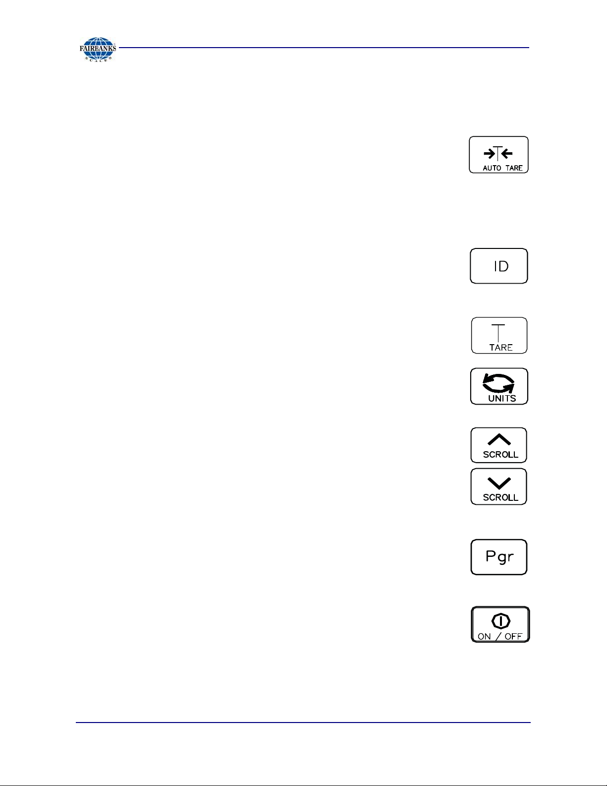
2.3. FRONT PANEL KEY FUNCTIONS, CONTINUED
AUTO TARE
In the Gross or Net mode, this key sets Tare Memory equal to the Gross
Weight on the platform.
─ The instrument displays "0" weight and enters the Net Weigh
mode.
─ The NET Legend displays.
─ Auto Tare only operates if the Gross Weight is positive.
ID KEY
Enters numeric ID for printer or computer printout.
─ A maximum of six digits is available, 0 thru 999999.
TARE KEY
Displays the currently entered Tare Value.
UNITS KEY
Toggles the displayed weight between the units selected in the
Configuration Program (i.e. lb to kg or kg to lb.)
SCROLL KEYS
Moves through the Programming Menu Tree in an UPWARD or
DOWNWARD direction.
PROGRAM KEY
Enters into the instrument's Programming mode.
ON/OFF KEY
Turns instrument ON or OFF.
If the Sleep Function is selected, this key either disables or
enables the Sleep mode.
01/12 20 50647 Rev. 9
Page 21
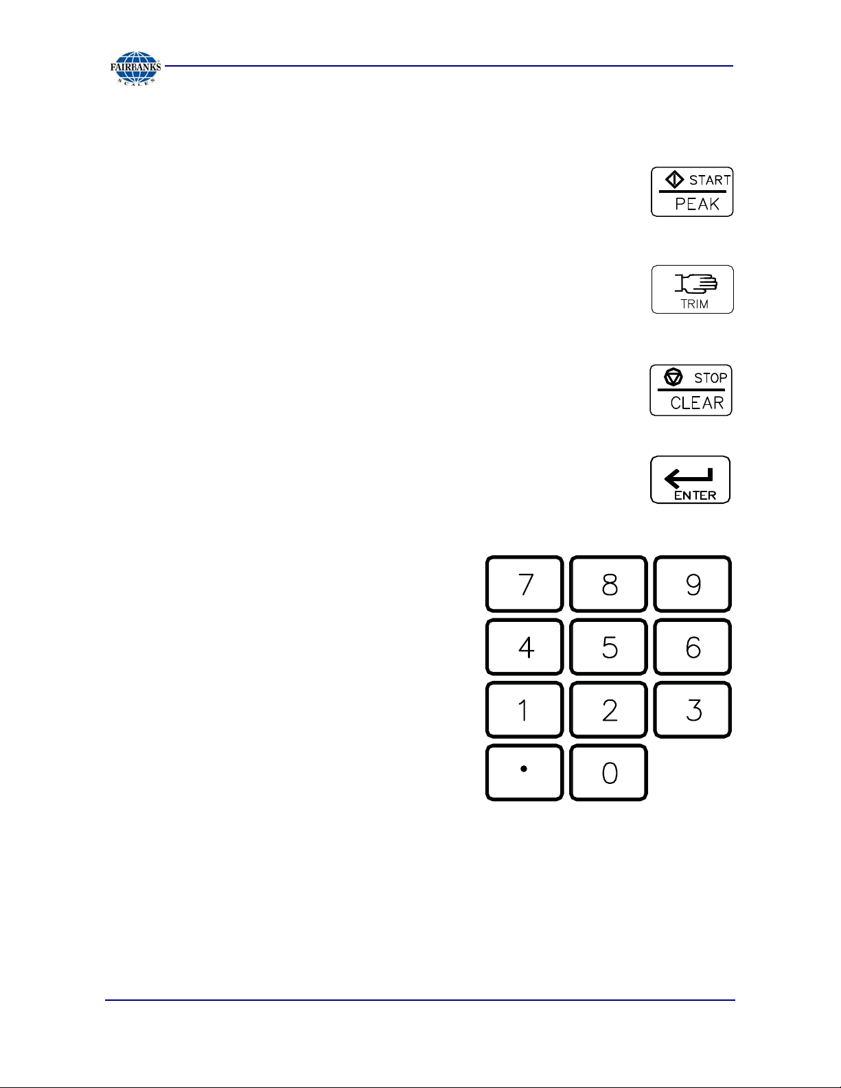
2.3. FRONT PANEL KEY FUNCTIONS, CONTINUED
START/PEAK KEY
Initiates a Setpoint Operation.
Also enables Peak Net Tracking (PNT).
TRIM KEY
Overrides the Setpoint Cycle.
Adds weight in touch-controlled increments.
STOP/CLEAR
Terminates a Setpoint Cycle.
Resets the memory of the Peak Net Capture to a null value until
a new Peak Net Weight is captured.
Section 2: Operation
ENTER
Inputs commands to the Setpoint Operation.
NUMERIC KEYS (0 THRU 9)
Used for numeric entries, such as Tare, ID,
Setpoint Values, etc.
LCD DISPLAY
Displays weight on the load receiver and applicable prompts.
01/12 21 50647 Rev. 9
Page 22
2.3. FRONT PANEL KEY FUNCTIONS, CONTINUED
Section 2: Operation
2497
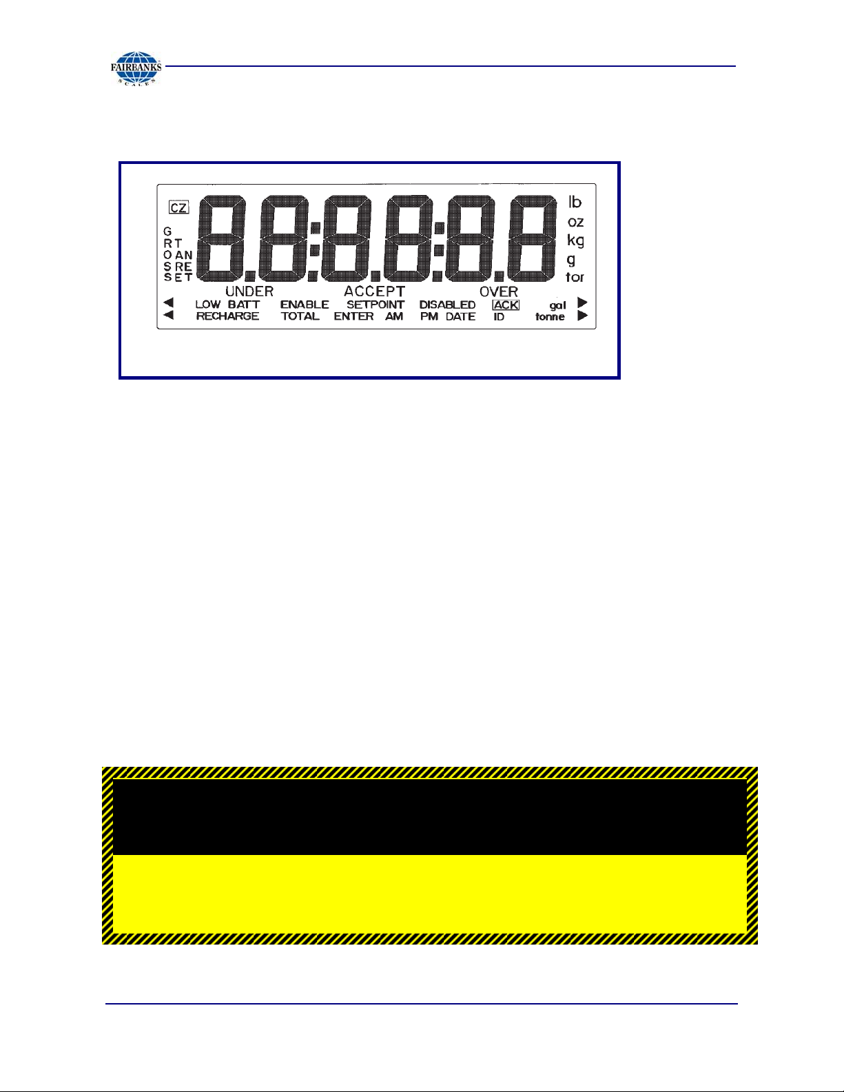
2.3.1. LEGENDS
Several different legends display on the LED screen.
While most are self explanatory, the following items are defined.
CZ (Center of Zero).
RECHARGE
Battery power is low and will require recharging soon.
The RECHARGE legend displays when the input voltage from the Battery
Accessory 2830 falls below a threshold of approximately 5.4VDC when using
Accessory 2802, or 5.32VDC when using Accessory 2880.
01/12 22 50647 Rev. 9
CAUTION
Battery surfaces get very HOT during recharging.
Page 23

Section 2: Operation
2.3.1. LEGENDS, CONTINUED
LoBAtt
Battery requires immediate recharging.
The RECHARGE legend disappears and the instrument automatically shuts down
and displays LoBAtt when the voltage from the battery falls below the following:
5.3VDC when using Accessory 2802
5.12VDC with Accessory 2880.
CAUTION
Batteries which measure below 4.0 VDC must not be charged with the ACC
2840 or ACC 2841 chargers, or damage to the charger and/or battery may occur.
2.3.2. INSTRUMENT WEIGHING FUNCTIONS
Three terms which describe the distribution of an object's weight are GROSS
WEIGHT, TARE WEIGHT, and NET WEIGHT.
TARE WEIGHT
Tare weight is the weight of the incidental materials, such as its container.
NET WEIGHT
Net weight is the weight of only the primary materials.
01/12 23 50647 Rev. 9
Page 24

Section 2: Operation
2.3.2. INSTRUMENT WEIGHING FUNCTIONS
GROSS WEIGHT
Gross weight is the total weight of a weighment.
─ This includes any primary and incidental materials comprising the total
weighment.
TARE WEIGHT VALUE + NET WEIGHT VALUE = GROSS WEIGHT
A Working Example
A can of house paint is an object to be weighed. The can is the incidental material
used to hold the primary material, paint, and the label is incidental material used to
identify the paint. All the incidental materials summed together comprise the Tare
weight. All the primary materials weights summed together comprise the Net weight;
in this case pigment, base, and solvent. The object is made up of incidental
materials, can and label, and primary material, paint. Summed together, the complete
object is the Gross weight.
GROSS = NET + TARE
TARE = GROSS – NET
NET = GROSS – TARE
NET = GROSS - TARE is particularly important because it is what a scale uses
to compute net weights in the NET WEIGHING mode.
Gross Weight is a function of the total weight on the platform from the zero reference.
Tare Weight is always an operator defined value.
01/12 24 50647 Rev. 9
Page 25

Section 2: Operation
2.3.3. GROSS WEIGHING
1. Press the key to select Gross as indicated by the legend.
2. With the platform empty, press the key.
─ The display indicates ZERO.
─ The Center-of-Zero (CZ) legend appears.
3. Place the object to be weighed on the scale platform.
─ The weight of the object displays.
─ The instrument is only able to measure the weight on the platform.
─ The instrument can not tell if the weight is from the object to be weighed or
from some other objects left on the platform.
─ The operator must tell the scale when there is nothing on the platform to
weighed by pressing the key.
─ The instrument will assign whatever weight happens to be on the platform a
zero weight value.
─ Starting with an empty platform is not required.
─ The key sets the display to "0", regardless of what is on the platform.
─ Weighing in the Gross mode consists of pressing the key and
placing a weight on the platform.
─ The display shows the Gross Weight of the object.
─ The instrument understands Gross Weight as the total weight placed on the
platform after the key is pressed.
2.3.4. TARE WEIGHTS
Tare weight is operator-defined. There are two methods to input a tare weight value.
Keypad Tare Entry
Assign the tare weight value using the numeric keypad, then press the
key. The instrument will change to the Net Weighing mode, and display the Gross
Weight less the Keypad Tare weight entry.
01/12 25 50647 Rev. 9
Page 26

Section 2: Operation
2.3.4. TARE WEIGHTS, CONTINUED
Auto Tare Entry
Place the item(s) that will comprise the Tare weight onto the scale and press the
key. The instrument will Change to the Net Weighing mode, and display the Gross
Weight less the Auto-tare weight entry. The tare weight value remains unaltered in
the instruments memory until the following occurs.
1. Power is removed.
2. The key is pressed.
3. A new tare weight is entered via the keypad.
4. The Program Menu is accessed.
─ If the value of the tare weight entered using the keypad does not correspond
with an exact division size, the number is first truncated to the correct decimal
location, and then rounded to the nearest division size.
─ For example, for a division size of 0.1, an entered tare of 2.19 is truncated to
2.1. It is then rounded to a final tare of 2.1.
─ For a division size of 20 an entered tare of 511 will be truncated to 510 and
then rounded to a final tare of 520.
5. Correct entry errors by inputting "0's" until a single "0" is displayed
6. Press the key.
Net Weighing Using AUTO TARE
1. Press the key. The display will read "0" and the GROSS Legend will be
displayed.
2. Place the empty container on the platform.
3. Press the key.
─ The scale displays "0" and the NET legend is also displayed. The weight of the
container on the scale will be entered in to the instruments memory as a TARE
weight value.
01/12 26 50647 Rev. 9
Page 27

Section 2: Operation
2.3.4. TARE WEIGHTS, CONTINUED
4. Place the material to be weighed in the container. The display will show the
weight of the material that is in the container. This is the NET weight value.
NOTE:
placing an empty container that is the same weight as the product container on the
platform, and pushing before beginning weighing operations.
Net weighing of pre-packaged containers can be accomplished by first
Batching Using AUTO TARE
1. Select the GROSS Mode and place the empty container on the platform.
─ the TARE Weight of the container is displayed.
2. Push the key.
3. Fill the container with the first item until the desired weight is achieved. Instrument
display indicates the net weight of the first item (in the GROSS mode).
4. Push the key to reset the display to zero.
─ The instrument display indicates zero net weight.
5. Place the next item into the container until the desired weight is reached.
6. Repeat Steps 4 and 5 until all items have been put into the container.
7. Switch to the GROSS Mode and read the total NET weight of the batch.
8. Repeat Steps 1 through 7 for other batches.
Follow these steps to clear the operation.
1. Select the GROSS mode.
2. Remove all materials from the platform.
3. Push the key to zero the display.
4. Push the key to reset the tare memory.
5. Select the GROSS mode.
01/12 27 50647 Rev. 9
Page 28

Section 2: Operation
2.3.4. TARE WEIGHTS, CONTINUED
ENTERING ID Numbers
1. Place the instrument into the Weighing mode.
2. Press the key.
─ The current ID number or id none will be displayed.
3. Use the numeric keypad to assign an ID number.
─ A maximum of six digits, 0 through 999999.
4. Press the key to save the displayed ID number and to return the
instrument to the Weighing mode.
─ The ID number is printed as part of each print cycle if selected in the IO
Output Programming.
Peak Hold Function
The PEAK HOLD (P hoLd) function is used to determine, display, and print the
largest Net weight data achieved during a weighing cycle. A weigh cycle ends when
the Print command is given, or when the peak Net weight is manually cleared by the
CLEAR key. PEAK HOLD tracks only Net weight, and operates independently of the
display. The peak weight can either be a positive or a negative number, determined
by the absolute weight value. This means that if a positive peak is displayed, a
negative weight value of greater absolute value could update the peak information in
the same cycle.
If the P hoLd option is activated in the IO Menu, then pressing the START key
enables this function
─ It allows the viewing of the current peak net weight.
Pressing ENTER returns the display to the Weighing mode.
─ The P hoLd feature works in the Gross or Net Weighing modes.
1. Place a container on the scale.
2. Press the AUTOTARE key, or enter in a known TARE Weight.
3. Press the START/PEAK key to view the current Peak Net Weight.
4. Press the ENTER key to enable the feature and return to the Weighing mode.
5. Perform the desired number of weighment’.
01/12 28 50647 Rev. 9
Page 29

Section 2: Operation
─ At any time, the current Peak Net Weight can be viewed by pressing the
START/PEAK key.
─ Press the ENTER key to return the Weighing mode.
6. If a printer is enabled, pressing the PRINT key will have the Peak Net Weight
transmitted with the printed data.
─ A print command ends the “Peak hoLd” Weighing Cycle.
7. Press the STOP/CLEAR key to reset the current Peak Weight, and press the
START/PEAK key followed by the ENTER key to enable the feature.
01/12 29 50647 Rev. 9
Page 30

Section 3: Programming
3.1. MENU NAVIGATION
The instrument must be programmed before it can be used. The program is arranged
in a menu tree format. Once the Programming mode is entered, menu's may be
accessed in any order by following the flow charts on the following pages.
tArGEt
SEE PAGE 29
inFo
SEE PAGE 30
io
SEE PAGE 32
CAnnEd
ConFig
CAL
LEGEND : :
= CONDITIONAL PROGRAMMING MENU ITEMAbCd
2800navo
The graphic model shows the Main Menu Tree options and several levels of sub-
menu options. On the following pages, menus are displayed graphically starting with
a specific main menu option, its sub-menu's, and ending with the data within each
that can be selected and saved. Each graphic shows lines as the paths to follow
while navigating the menu.
01/12 30 50647 Rev. 9
Page 31

Section 3: Programming
3.1. MENU NAVIGATION, CONTINUED
Keys Used for Navigation
The SCROLL keys are used to navigate through menu options or data in an
UPWARD or DOWNWARD direction. Continually pressing either SCROLL key
cycles through the available options.
The ENTER key accepts and/or stores the displayed option or data entry. Press
ENTER at a menu option to access the sub-menu's and data contained in that option.
In the following flow charts, Enter is expressed as a lateral navigation key.
The B/G NET key exits most programming menu's returning to the previous menu.
Continually pressing the B/G NET key exits programming and returns to the Weight
Screen. In the following flow charts, B/G NET is expressed as a lateral navigation
key.
MAIN MENU DESCRIPTIONS
MENU ITEM DESCRIPTION
tArgEt
info
io
U CodE
(User Code)
CAnnEd
ConFig
CAL
Conditional statement that appears if the setpoints are active.
No password is required.
Allows the operator to set target weights as defined by Setpoint mode.
See page 29 further details.
No password is needed.
Displays instrument data.
Prints Audit Reports.
See page 30 for further details.
"U" Code is required,.
Sets the time and date.
Programs all I/O Ports for printers and other accessory devices.
See page 32 for further details.
Used by an operator to access the IO Menu.
Not operator accessible.
Not operator accessible.
Not operator accessible.
01/12 31 50647 Rev. 9
Page 32

3.2. TARGET MENU DESCRIPTION
This area is for the numeric entry of target
weights by the operator.
─ No sub menu selections are
available.
─ Note that the Status Display
shows the current setpoint being
programmed.
tArGEt
inFo
Section 3: Programming
xxxxxx
xxxxxx
xxxxxx
tArgEt 1
tArgEt 2
tArgEt 3
1. Use the SCROLL keys to select the
setpoint to be programmed.
2. Key in the desired target weight using
the numeric keypad including the
decimal point, if applicable.
3. Press the ENTER key.
4. When all applicable setpoints have
been programmed, press the
B/G NET key.
─ The SToRE displays.
5a. If the ENTER key is pressed, the display will indicate SToRED momentarily and
then TARGET. Pressing B/G NET again will exit to the weigh screen.
5b. If the SCROLL key is depressed, it will toggle between SToRE and CANCEL.
io
CAnnEd
ConFig
CAL
xxxxxx
xxxxxx
xxxxxx
xxxxxx
xxxxxx
tArgEt 4
tArgEt 5
tArgEt 6
tArgEt 7
tArgEt 8
─ The CANCEL prompt gives the operator the option of exiting without saving
changes.
6. Select CANCEL and press the ENTER key, the display will show TARGET.
7. Pressing the B/G NET key will exit to the weigh screen.
01/12 32 50647 Rev. 9
Page 33

Section 3: Programming
3.3. INFO MENU DESCRIPTION
The info menu is user accessible without a security code. This menu may be
checked by Weights & Measures to view the
C Audt entries, or the operator, service technician for diagnostic and
informational purposes. This menu contains the following menu selections.
tArGEt
S Audt, U Audt, or
inFo
io
CAnnEd
ConFig
CAL
CoUntS
rEPort
C SEnS
hoUr
dAtE
C AUdt
S AUdt
CELL 1
Up to
16
hrdCPY
x.xxxx
xx:xx:xx
xx.xx.xx
xxxxx C dAtE xxxxxx hrdCPY
xxxxx
S dAtE
xxxxxx
hrdCPY
U AUdt
bAtt
dEg C
01/12 33 50647 Rev. 9
xxxxx
x.xx dC
xx.x C
U dAtE
xxxxxx
hrdCPY
Page 34

3.4. MAIN MENU DESCRIPTIONS
MENU ITEM DESCRIPTION
CoUntS
dEg C
bAtt
U AUdt
S AUdt
C Audt
dAtE
hoUr
C SEnS
rEPort
hrdCPY
Formatted CELL X, where x represents the load cell currently being
displayed, the load cells are selectable using the SCROLL key.
The small display shows two numeric values.
─ The first value is the Initial Deadload or Zero Counts.
─ The second is the Current Liveload Count(s).
Formatted XX.X°C.
Displays the current internal temperature of the instrument in Centigrade.
Displays XX.XdC.
The current battery voltage.
User Audit.
Service Audit.
Calibration Audit.
Displays MM.DD.YY.
The current system date.
Displays HH.MM.SS.
The current system time.
For viewing purposes only.
Refer to the IO Section for programming.
mV/V of cell(s) currently selected.
All cells may be viewed using the SCROLL key.
For printing a configuration report to an installed printer.
A conditional statement appearing only when a printer is installed on IO Ports
A or B.
Section 3: Programming
01/12 34 50647 Rev. 9
Page 35

3.5. I/O MENU
tArGEt
inFo
io
CAnnEd
ConFig
tArGEt
Port b
dAtE
hoUr
SdELAY
xxxxxx
xx.xx.xx
xx:xx:xx
x.x
UnUSEd
SEtPoint
PoLL
PoLLid
Printr
Contin
Up to 8
entries
SEtPoint
PoLL
PoLLid
rS232
rS485
rS232
rS485
Section 3: Programming
SPhAnd
SPAUto
SPnonE
SPALrt
SPChEC
SPCont
id xxx
CAL
SLEEP
gALCon
0ShiFt
tArEoP
PhoLd
FodiSt
PrtLoC
PtroPt
4-20
ConoPt
ProtoA
Port A
Protob
x.xxhr
0-20%
Short
Long
grLooP
ntLooP
nogAL
gAL
nonE
both
tA Ent
AUto
nohoLd
hoLd
bUSYLo
buSYhi
P3550
P3921
P3960
P3950
P610
LoSEt xxxxx hiSEt xxxxx 4 AdJ xxxxx Agtest
3052r
FbStd
FbPutr
troniC
ConCon
bAUd
UnUSEd
Printr
Contin
bAUd
300
600
1200
2400
4800
9600
19200
300
600
1200
2400
4800
9600
19200
gL1
gC1
nL3
nC1
tL2
tC1
iL4
iC1
hL5
hC1
dL6
dC1
PL7
PC1
Ln15
ChAr
noALog
AnALog
ChAr
20 AdJ
7
PAritY
8
7
PAritY
8
nonE
EVEn
odd
nonE
EVEn
odd
xxxxx
01/12 35 50647 Rev. 9
Page 36

Section 3: Programming
3.5.1. I/O MENU DESCRIPTIONS
The IO (Input/Output) Menu sets up communications for sending data to devices,
such as computers, printers, or remote displays. It also contains a menu for setting
the time & date.
MENU ITEM DESCRIPTION
Port b
dAtE
Steps for Setting the Date
1. With dAtE displayed, press the ENTER key.
─ The present date in memory displays with a small legend date flashing .
2. Using the numeric keypad, enter the current date.
─ Use the MM/DD/YY (month/day/year) format.
Programs Setpoint modes, remote displays, printer, and computer outputs.
Adjusts the date.
3. Press ENTER.
─ Once complete, the display returns to the dAtE.
MENU ITEM DESCRIPTION
hoUr
Adjusts the time.
Steps for Setting the Time
─ With hoUr displayed, press the ENTER key.
─ The present time in memory displays with a small legend time flashing.
─ Using the numeric keypad, enter the current date.
─ Use the HH/MM/SS (hour/minute/second) format.
─ When entering the time of 08:35am for example, press the numeric keys
3,
5, followed by the AUTOTARE key.
─ The time 08:35A.
─ The AUTOTARE key is used to enter an A for AM.
─ The
PRINT key is used to enter P for PM.
─ For military time (24 hour format), enter the current time using the numeric
keypad and press the ENTER key.
0, 8,
01/12 36 50647 Rev. 9
Page 37

3.5.1. I/O MENU DESCRIPTIONS, CONTINUED
MENU ITEM DESCRIPTION
SdELAY
SLEEP
Activates the Sleep Delay mode in minutes and/or seconds between ingredients
in a batch file of selected setpoints if the Auto Batch mode is on.
The Sleep Delay adjusts the length of time the instrument is inactive before
going to sleep.
─ 0.00 hr or X.XX hr (hrs & min) is displayed.
─ Use the SCROLL keys to adjust as required.
─ A setting of 0.00 hr disables the Sleep Function.
Section 3: Programming
NOTE:
The Sleep mode will not activate if Recharge displays. The Sleep
mode will also not occur when in the SPAUto or SPhAnd modes if relays are
energized.
EXAMPLE
MENU ITEM DESCRIPTION
gALCon
4. In the Gross Weigh mode, note the displayed amount.
5. Press the UNITS key to toggle to the Gallons (GaL) display.
─ The number of gallons displays.
6. Press the
─ The amount displays (
7. Press any numeric key.
Weight-to-Gallons Conversion Option.
When Gallon is selected, the
gallon units.
UNITS key toggles the display from weight unit to
TARE key to adjust the number of gallons.
Gallons Factor).
─ A UCoDE window displays.
8. Enter the code using the numeric keypad.
9. Press ENTER.
─ The current date flashes in the display.
─ “Entering Gallons” also displays.
01/12 37 50647 Rev. 9
Page 38

Section 3: Programming
3.5.1. I/O MENU DESCRIPTIONS, CONTINUED
10. Press ENTER again.
─ The current gallon per weight displays.
11. Clear the display by pressing the numeric ZERO key until it is blank.
12. Key in the correct number of gallons.
13. Press
ENTER.
─ The amount of gallons displays.
14. Press the UNITS key to toggle from weight to Gallons and confirm the correct
weight to gallons ratio.
NOTE: The Tare Mode is unavailable in Gallon Conversion Mode.
MENU ITEM DESCRIPTION
0ShiFt
tArEoP
tA Ent
P hoLd
FodiSt
PrtLoC
Sets the Capacity Percentage of the Positive Weight Shift on the scale.
─ Zeros the scale before an error code (i.e. lc error) displays in the small
window display.
─ Press the
weighing.
Tare options include AUto (Using the
Using the numeric keypad, enter a known Tare Weight.
Peak Weight options are Hold and No-Hold.
─ If enabled, this holds the highest recorded NET Weight Reading.
─ Not used while in the Setpoint mode.
If a Device Output is selected, there are two fiber optic distance options.
─ 0-99 ft. = Short
─ 100+ ft. = Long
Formats all available printer locations, if a ticket printer is selected in either port.
The following prompts apply when formatting the printer.
ZERO key a second time zeros the scale and continues its
AUTOTARE key).
01/12 38 50647 Rev. 9
Page 39

Section 3: Programming
3.5.1. I/O MENU DESCRIPTIONS, CONTINUED
NOTE:
The references to Line are as seen from the top of page down, and the
Column is equal to one character space width.
PROMPT COMMENT CHOICES
bUSYh
gL 1
gC 1
nL 3
nC 1
tL 2
tC 1
iL 4
iC 1
hL 5
hC 1
6
dC 1
PL 7
PC 1
Ln 15
no Leg
Busy Line bUSYhi, bUSYLo
Gross Line
Gross Column
Net Line
Net Column
Tare Line
Tare Column
ID Line
ID Column
Hour (Time) Line
Hour (Time) Column
Date Line
Date Column
'Peak' Line (if enabled)
'Peak' Column (if enabled)
Length (Total Lines Printed)
Legend/No Legend no LEg, grtAnt
EXAMPLE
Using the basic format below, to place time and date on the same line requires the
following settings.
hL5
hC1
dL5
C15
NOTE: Peak Net Weight must be printed to a GTN format.
3.5.1. I/O MENU DESCRIPTIONS, CONTINUED
MENU ITEM DESCRIPTION
PtroPt
4-20
Selects the printer type.
─ Options include P3550, P3921, P3960, P3950, P610, P3921.
Sets the 4-20 Analog Output.
01/12 39 50647 Rev. 9
Page 40

Section 3: Programming
NOTE: The 4-20mA Output is enabled by selecting AnALog in Port A.
CAUTION
The 4-20ma accessory is a passive device!
The power is to be supplied by others, and MUST
BE
a DEDICATED and an ISOLATEDpower supply.
MENU ITEM DESCRIPTION
4-20
─
─ grLooP: Tracks the GROSS Weight.
─ ntLooP: Tracks the NET Weight.
PROM Version 6.2+ Notes
The 4-20mA output remains locked on the last reading at the time the PGR
was pressed.
An Overload (oL) condition produces a reading of 24mA.
An Underload (UL) condition produces a reading of 3.5mA.
While in the Sleep mode, the 4-20mA produces a reading of 3.5mA, and it is
not tracked until the instrument is re-activated.
01/12 40 50647 Rev. 9
Page 41

3.5.1. I/O MENU DESCRIPTIONS, CONTINUED
PROMPT COMMENT(S)
LoSEt
hiSEt
4 AdJ
20 AdJ
AgtESt
Sets the weight value associated with 4mA.
Usually "0".
1. At the LoSEt prompt, press ENTER.
2. Use the numeric keypad to enter desired weight value.
3. Press ENTER.
Associated weight value of 20MA.
Usually the capacity of the scale.
1. Press ENTER at the hiSEt prompt.
2. Use the numeric keypad to enter the desired weight value.
3. Press ENTER.
Press ENTER to display a current number representing the 4mA Output.
─ See note on key functions.
Press ENTER to display a current number representing the 20mA
Output.
─ See note on key functions.
LP4 - TO - LP22.
Press ENTER to perform an analog test.
4mA thru 22mA will be output momentarily in 2mA steps.
When adjusting either 4mA or 20mA, the following numeric keys increase
or decrease the reference value in the fashion that follows.
Increased by: Decreased by:
9 10,000 4 10,000
8 1,000 3 1,000
7 100 2 100
6 10 1 10
5 1 0 1
Section 3: Programming
ConoPt
Used for Continuous Output.
Choices include the following:
3052r FbStd FbPUtr troniC ConCon
ProtoA
Protocol setting for Port A choices include selections for the following:
bAUd 9600, 600, 1200, 2400, and 4800
ChAr 8 and 7
PAritY nonE, odd, and EuEn
01/12 41 50647 Rev. 9
Page 42

3.5.1. I/O MENU DESCRIPTIONS, CONTINUED
PROMPT COMMENT(S)
Port A
noALog, AnALog
Protob
tArgEt
Port b
Poll
Poll id
Port A has available selections of the following:
UnUSEd - no outputs
Printr - printer output
Contin - continuous output
Used to turn on or off the 4 - 20MA output.
noALog = Off
AnALog = On
Protocol setting for Port A choices include the following:
bAUd 9600, 600, 1200, 2400, and 4800
ChAr 8 and 7
PAritY nonE, odd, and EuEn
Conditional, if setpoints are selected in Port B.
1. Press
2. Enter a new Target Weight Value with the numeric keypad.
3. Press
Port b can be configured for the following:
UnUSEd - no outputs
* SEtPnt - Setpoint modes
* PoLL or PoLL id - computer output
Printr – printer
Contin - continuous output
Used for Demand Output to a computer.
When the instrument receives an upper-case "W" followed by a
carriage return ("W", "Cr") from the PC, a data stream transmits.
See Appendix VII for ASCII Chart.
Use this demand mode when a specific instrument ID is required.
Setup by entering the required ID's decimal equivalent.
See Appendix VII for ASCII Chart.
ENTER to adjust the Setpoint Target Weight Menu.
─ The large display shows the Current Target Weight Value
associated with the Target Number, as shown in the small
display.
─ The
SCROLL key toggles through available Setpoint Relays
(Targets).
ENTER to accept the new weight value and advance to the
next available target.
Section 3: Programming
01/12 42 50647 Rev. 9
Page 43

Section 3: Programming
3.5.1. I/O MENU DESCRIPTIONS, CONTINUED
EXAMPLE
The required ID is 3 (decimal equivalent is 51).
1. Press the ID key.
─ Either idnonE or the current ID shows in the large display.
2. Using the numeric keypad, enter 51.
3. Press ENTER.
─ When the PC sends ID 3, then a upper case W followed by a C carriage
return (
transmission.
3, W, Cr), the instrument with that ID responds with a data
SEtPnt
The operation of Setpoint requires that accessories 5806 (Fiber Optic Cable)
and 2850 (Safe Area Relay Box) be installed. There are five modes of setpoint
operation that may be selected from during the installation and programming by your
local Fairbanks Service Center or Authorized Factory trained Distributor.
SEtPnt Modes
PROMPT CHOICE(S)
SPCont
SPChEC
SPALrt
SPAUto
SPhAnd
Continuous operation of setpoints, ON at entered target weight.
MUST press START to begin function.
Check weighing, such as UNDER/ACCEPT/OVER, with setpoint
Relays 1 and 2 active for alarms.
Setpoint Relay 8 is active, used as both LOW and HIGH alarms in
SoLo mode.
Or Relays 4 and 8 if in Paired mode.
Automatic batching, a range of materials can be added one at a time to
complete a batch.
SPAUto will not function when in the Gallons mode.
When configuring SdELAY, to perform the delay in minutes and
seconds between ingredients, the setting is located in the main I/O
Menu.
This operation requires a manual START at each setpoint.
01/12 43 50647 Rev. 9
Page 44

3.5.1. I/O MENU DESCRIPTIONS, CONTINUED
TARGET MENU
PROMPT CHOICE(S)
tArgEt
Used for programming weight values associated with setpoint-relays.
Target 1 = relay 1 and Target 2 = relay 2, through rest of programmed
setpoints.
The number of targets will vary depending on number selected during
initial setup. Modifications should be performed with caution.
The Setpoint mode determines the target function, and targets should
be programmed accordingly.
SEtPnt MODE
Target Assignment
PROMPT CHOICE(S)
SPCont
SPChEC
Target 1 thru X (where X is the total number of setpoints) are the
programmed number of setpoint relays.
Single-value relays that energize when their assigned weight value is
reached or exceeded.
These relays, as a group, are manually controlled by the START and
STOP front panel keys.
No Autoprint available in this mode.
In the Check Weigh mode, Target 1 is the UNDER range setpoint-
Relay 1.
It is on-active if the weight is equal to or below its assigned weight
value.
Target 2 is the OVER range setpoint-Relay 2.
It is Active when the weight is equal to or above its assigned weight
value.
The ACCEPT range is the weight between UNDER and OVER.
It is selected to operate either the Gross or Net modes.
Section 3: Programming
NOTE:
The legends for UNDER, ACCEPT, and OVER show on the large display
when its associated weight value is active.
There is not a relay output for the ACCEPT range.
When using the
absolute value displayed (+/-) in the Gross mode and to the positive value
displayed in the
01/12 44 50647 Rev. 9
SPCont or SPChEC modes the relays respond to the
Net mode.
Page 45

Section 3: Programming
3.5.1. I/O MENU DESCRIPTIONS, CONTINUED
PROMPT CHOICE(S)
SPALrt
─ The following applies to either of the Setpoint Batch modes, whenever the
weight on the scale is below or above the Alert Value, and the Alert is
enabled. The alert relay(s) toggle On/Off when the following occurs.
The front panel keys are pressed.
The instrument comes out of its Sleep mode.
Used for ALARM purposes.
In the SoLo mode only Relay 8 is used, for both the LOW and HIGH
alarm.
In the paired mode, Relays 4 and 8 are used.
The setpoint-relay will be active when the GROSS weight is equal to or
below the programmed LOW ALARM weight value or equal to or
above the programmed HIGH ALARM weight value.
The SPALrt targets are only programmable in the IO Port B Menu.
The SPALrt may be used with all other setpoint modes except whenever
four (4) paired setpoints are programmed.
If SPALrt is enables in conjunction with any other setpoint option, the
instrument prompts for Alarm low wgt, causing an Alarm high wgt.
Alarm IO must be set to a value other than zero.
01/12 45 50647 Rev. 9
Page 46

3.5.1. I/O MENU DESCRIPTIONS, CONTINUED
PROMPT CHOICE(S)
SPAUto
A Batching mode, allowing the operator to press the START key once to
add multiple materials automatically
─ It allows SoLo (single setpoint-relay) or PAIRED (dual setpoint-
relays) setpoint(s).
─ In the SoLo mode. Targets 1 thru X represent the required
weight of each individual material.
─ In the PAIRED mode, Targets 1 thru 4 represent the Bulk or
Fast-Fill Relays
─ Targets 5 through 8 are the slow or target.
─ Note the association of paired setpoints-relay:
1-5 2-6 3-7 4-8
Always program the Bulk-Fast Fill Setpoint-Relays to a lesser weight
value than the complete material weight value
─ Configure the Target-Slow Fill Setpoint-Relays assigned to the
complete material weight value.
─ When using multiple materials, set the SdELAY (timer for start of
next material relays) in the IO Menu.
─ If a printer has been selected, an auto print occurs when target
value is reached.
─ SPAUto is not available in the gallons mode.
SPAUto EXAMPLE
Below is an example of a simple, two (2) material batch with PAIRED
relays.
FUNCTION TARGET NUMBER
─ Material 1 bulk - fast fill
relay (1)
─ Material 2 bulk - fast fill
relay (2
─ Not used ─ 3
─ Not used ─ 4
─ Material 1 target - slow fill
relay (5)
─ Material 2 target - slow fill
relay (6)
─
Section 3: Programming
─ 1
─ 2
─ 5
─ 6
01/12 46 50647 Rev. 9
Page 47

3.5.1. I/O MENU DESCRIPTIONS, CONTINUED
PROMPT CHOICE(S)
SPhAnd
SPhAnd SPALrt
EXITING MENUS
The Manual mode of a batching process.
─ Each separate material is operator-selected by using the
SCROLL key, and then pressing START.
─ This sequence must be continued until the batch is complete.
─ If a printer is selected, an auto print occurs when target value is
reached.
─ Further detailed programming includes the following in order to
define this modes operation.
Gross (groSS) Net (nEt) Single relays (SoLo)
Dual relays (PAirEd) Upweighing (UP)
Downweighing (not UP)
Down weighing is a net mode function and requires an
─ initial weight of zero. The instrument must have an auto tare
performed prior to beginning the setpoint operation.
─ SPhAnd is not available in the Gallons mode.
Used for ALARM purposes.
Only setpoint-relay (8) is used for both the LOW and HIGH alarms.
The setpoint-relay actives when the GROSS weight is equal to or
below the programmed LOW ALARM weight value, or equal to or
above the programmed HIGH ALARM weight value.
Set the LAST to the following value, if Paired is selected:
PAIRED LAST
1 5
2 6
3 7
4 8
Relays (4) and (8) are conditional on selection of the SPALrt feature.
When exiting the TARGET or IO menus, either store or canceling the
changes.
─ When prompted to SToRE, press ENTER to save the changes.
─ The display momentarily reads SToRED, and then returns to the
root menu prompt.
─ With SToRE displayed, press the SCROLL key to select the
CANCEL option
─ Press ENTER and no changes are saved.
Section 3: Programming
01/12 47 50647 Rev. 9
Page 48

Section 4: Security
4.1. SECURITY CODES
PROMPT CHOICE(S)
UCodE
DISPLAYED PROMPTS REQUIRED ACTIONS
UCodE
P
PU
PUC
PUCi
PUCin
PUCini
noSEAL
nUPASS
CLrFin
XX.XX.XX
User Code
Provides access for the operator /supervisor to the user programmable options.
USE CAUTION when making changes to the system.
1. Press the
2. Press the UNITS key.
3. Press the
4. Press the ID key.
5. Press the hidden key (between) ID and TARE.
6. Press the ID key.
7. Press the
8. Use the SCROLL key to choose either noSEAL.
(noncommercial) or SEAL (commercial) set, depending on
the
local jurisdiction.
9. Press the ENTER key.
10. Using the numeric keypad, enter the new user code.
11. Press the
12. Use the SCROLL key to choose either CLrFin
(password
needed upon menu re-entry) and CLrPon (password
needed
after power-up).
13. Current date. If correct, proceed by pressing the
key, or enter correct date using the numeric keypad.
PRINT key.
Pgr key.
ENTER key.
ENTER key.
ENTER
Follow these steps to create or change a
UCodE.
Follow the standard exiting procedures as noted in the Menu Navigation section
of this manual.
01/12 48 50647 Rev. 9
Page 49

Appendix I: Troubleshooting/Error Codes
FAULT CAUSE SOLUTION
-UL-- LOADCELL FAILURE
--oL-- LOADCELL
FAILURE
RECHARGE
LoBAtt
err 069
likely lc error
Scale restricted.
Debris under scale.
Scale behind 0.
Load Cell failure.
Overloaded Scale.
Load Cell failure.
Battery voltage low
between 5.4 to 5.32VDC.
Battery voltage low, between
5.3 to 5.12VDC
Programming input error.
0shift out of range
Load Cell Failure.
Correct the bind or restriction.
Remove debris under the
scale/cells.
Replace items removed from
the scale.
Call Fairbanks service.
Remove weight from the scale.
Call Fairbanks service.
Recharge the battery.
Recharge the battery
IMMEDIATELY.
Recycle the power to
instrument.
Remove weight from the scale.
Re-zero the scale.
Call Fairbanks service.
01/12 49 50647 Rev. 9
Page 50

Appendix II: FM Control Drawings
MJQ06-26-04
APP
06-14-01
01-17-01
1
----------- REVISIONS -----------
Rev Sheets 4 and 8
1
2
REV DESCRIPTION DATE
GAL6-9-09
07-02-03 MJQ
07-04-01
Rev Sheets 4 and 8
3
2-2-11 GAL
REV SHEETS 4 & 8 PER ECO 13552
ADDED SHEETS 11 & 12 PER ECO 14036
REV SHEETS 9 & 10 PER ECO 14187
Add Sheets 9 & 10 per ECO 13469
4
5
6
7
It(Io) = 190 ma
Vt(Vo) = 7.02v
FOR TB3, TB4, TB5 or TB6:
ENTITY OUTPUT PARAMETERS
Po = 0.38 w
La(Lo) GP A,B 2.3 mH
Ca(Co) GP A,B 14 uF
Ca(Co) GP C,E 42 uF
Ca(Co) GP D,F,G 84 uF
La(Lo) GP C,E 9.2 mH
TO TRANSDUCERS
La(Lo) GP D,F,G 18.4 mH
HAZARDOUS AREAS:
CL I, DIV 1 & 2, GP A, B, C & D
CL II, DIV 1 & 2, GP E, F & G
CL III
1 12Tuesday, July 03, 2001
21943
CONTROL/INSTALLATION DRAWING FOR 2800 INDICATOR
FAIRBANKS SCALES
2176 PORTLAND ST.
B
SUITE 1
ST,JOHNSBURY VT. 05819
Title
Size Document Number
Date: Sheet of
1
CL I Zones 0, 1, 2 GP IIC, IIB, IIA
2
FM approval) or CSA certified (for installations requiring CSA approval) for the
hazardous locations where they are installed and have appropriate
or between ACC-2802s shall not exceed wire size 16AWG.
and ANSI/ISA-RP12.6 "Installation of Intrinsically Safe Instrument Systems
in Class I Hazardous (Classified) Locations."
1. Installation shall be in accordance with the National Electrical Code(ANSI/NFPA 70)
2. Size of wires in cable between ACC-2825 and 2800 or between 2800 and ACC-2802
3. Strain gage based transducers must be FM approved (for installations requiring
NOTES:
entity parameters.
5. SEE SHEET 6 FOR 2800 GLAND SEAL LOCATIONS AND CABLE FUNCTIONS.
4. ALL UNUSED GLAND SEALS ARE PLUGGED.
B B
GLAND SEAL
TB3
ACC-2802
SECTIONAL CONTROLLER
PCB ASSY 18720
(PN 21234)
2800 INDICATOR
GLAND SEAL
TB2
PCB ASSY 18725
TB4
PCB ASSY 18468
GLAND SEAL
TB5
JP1
GLAND SEALS
GLAND SEAL
GLAND SEAL
TB6
16 AWG CABLE
20 FEET MAXIMUM
TB1 TB1
TB2
GS5
GS4
(SEE SHEET 5)
BATTERY PACK
PN 20615
ACC-2830
GLAND SEAL
A A
GROUPS A, B, C, D, E, F & G
GROUPS IIC, IIB & IIA
NO CHANGE MAY BE MADE TO THIS DRAWING OR RELATED
COMPONENTS WITHOUT PRIOR WRITTEN APPROVAL OF FACTORY MUTUAL!!!!
2
01/12 50 50647 Rev. 9
Page 51

Appendix II: FM Control Drawings
GAL
GAL
MJQ
APP
6-9-09
07-02-03
01-17-01
1
----------- REVISIONS -----------
REV DESCRIPTION DATE
ADDED SHEETS 11 & 12 PER ECO 14036
REV PER ECO 13469
1
6
4
GLAND SEAL
TB3
CONTROLLER
SECTIONAL
PCB ASSY 18720
ACC-2802
2-2-11
REV SHEETS 9 & 10 PER ECO 14187
7
GLAND SEAL
TB2
GROUPS C, D, E, F & G
GROUPS IIB & IIA
TO TRANSDUCERS
GLAND SEAL
GLAND SEAL
TB5
TB4
PCB ASSY 18468
TB6
JP1
TB1
GLAND SEAL
GLAND SEAL
TB3
CONTROLLER
PCB ASSY 18720
SECTIONAL
TB2
ACC-2802
Vt(Vo) = 7.02v
FOR TB3, TB4, TB5 or TB6:
ENTITY OUTPUT PARAMETERS
GLAND SEAL
GLAND SEAL
TB4
TB5
JP1
PCB ASSY 18468
It(Io) = 190 ma
Po = 0.38 w
TO TRANSDUCERS
TB6
SECTIONAL CONTROLLER
ACC-2802
TB1
Ca(Co) GP D,F,G 84 uF
Ca(Co) GP C,E 42 uF
La(Lo) GP C,E 9.2 mH
GLAND SEAL
GLAND SEAL
TB3
PCB ASSY 18720
TB2
La(Lo) GP D,F,G 18.4 mH
HAZARDOUS AREAS:
GLAND SEAL
TB4
TB5
JP1
PCB ASSY 18468
CL I, DIV 1 & 2, GP C & D
TO TRANSDUCERS
GLAND SEAL
TB6
TB1
CL II, DIV 1 & 2, GP E, F & G
CL III
CL I Zones 0, 1, 2 GP IIB & IIA
GLAND SEAL
GLAND SEAL
TB3
SECTIONAL CONTROLLER
PCB ASSY 18720
TB2
ACC-2802
SUITE 1
FAIRBANKS SCALES
GLAND SEAL
TB4
PCB ASSY 18468
2176 PORTLAND ST.
TB5
JP1
ST,JOHNSBURY VT. 05819
Title
GLAND SEAL
21943
CONTROL/INSTALLATION DRAWING FOR 2800 INDICATOR
B
Size Document Number Rev
TO TRANSDUCERS
TB6
TB1
2Tuesday, July 03, 2001
Date: Sheet
1
(SEE SHEET 5)
GLAND SEALS
2
16 AWG CABLE
50 FEET MAXIMUM
GLAND SEAL
TB1
GS5
TB2
BATTERY PACK
ACC-2830
GS4
PN 20615
GLAND SEAL
2
NO CHANGE MAY BE MADE TO THIS DRAWING OR RELATED
COMPONENTS WITHOUT PRIOR WRITTEN APPROVAL OF FACTORY MUTUAL!!!!
UP TO 4 ACC-2802s
PLUG SEAL FOR TB2 ON LAST ACC-2802
GLAND SEALS
B B
31 FEET MAXIMUM
16 AWG CABLE
GLAND SEALS
16 AWG CABLE
31 FEET MAXIMUM
GLAND SEALS
2800 INDICATOR
(PN 21234)
PCB ASSY 18725
A A
16 AWG CABLE
31 FEET MAXIMUM
01/12 51 50647 Rev. 9
Page 52

Appendix II: FM Control Drawings
GAL6-9-09
GAL2-2-11
MJQ07-02-03
APP
3Tuesday, July 03, 2001
01-17-01
1
----------- REVISIONS -----------
REV PER ECO 13469
ADDED SHEETS 11 & 12 PER ECO 14036
REV SHEETS 9 & 10 PER ECO 14187
1
6
7
4
REV DESCRIPTION DATE
GLAND SEAL
TB3
CONTROLLER
SECTIONAL
PCB ASSY 18720
TB2
ACC-2802
uF
21943
CONTROL/INSTALLATION DRAWING FOR 2800 INDICATOR
B
SUITE 1
ST,JOHNSBURY VT. 05819
FAIRBANKS SCALES
2176 PORTLAND ST.
Title
Size Document Number Rev
Date: Sheet
1
GROUPS C, D, E, F & G
GROUPS IIB & IIA
TO TRANSDUCERS
GLAND SEAL
GLAND SEAL
GLAND SEAL
GLAND SEAL
GLAND SEAL
It(Io) = 213 ma
FOR TB3, TB4, TB5 or TB6:
ENTITY OUTPUT PARAMETERS
Vt(Vo) = 7.875v
TO TRANSDUCERS
GLAND SEAL
GLAND SEAL
Po = 0.42 w
Ca(Co) GP C,E 5.6
Ca(Co) GP D,F,G 19 uF
La(Lo) GP C,E 2.4 mH
GLAND SEAL
GLAND SEAL
La(Lo) GP D,F,G 7.64 mH
HAZARDOUS AREAS:
GLAND SEAL
GLAND SEAL
CL II, DIV 1 & 2, GP E, F & G
CL I, DIV 1 & 2, GP C & D
TO TRANSDUCERS
CL III
CL I Zones 0, 1, 2 GP IIB & IIA
TO TRANSDUCERS
GLAND SEAL
GLAND SEAL
GLAND SEAL
GLAND SEAL
(SEE SHEET 5)
TB5
PCB ASSY 18468
TB6
JP1
TB1
TB3
SECTIONAL CONTROLLER
PCB ASSY 18720
TB2
ACC-2802
TB4
TB5
PCB ASSY 18468
TB6
JP1
TB1
TB3
SECTIONAL CONTROLLER
PCB ASSY 18720
ACC-2802
TB2
TB4
TB5
TB6
JP1
PCB ASSY 18468
TB1
TB5
TB4
PCB ASSY 18468
TB6
JP1
TB1
TB3
CONTROLLER
PCB ASSY 18720
SECTIONAL
TB2
ACC-2802
TB4
31 FEET MAXIMUM
GLAND SEAL
GLAND SEALS
16 AWG CABLE
50 FEET MAXIMUM
GS5
TB1
2
GLAND SEAL
UP TO 4 ACC-2802s
2
PLUG SEAL FOR TB2 ON LAST ACC-2802
GLAND SEALS
16 AWG CABLE
PN 18448
PCB ASSY 18414
ACC-2825
(SAFE AREA INTERFACE)
31 FEET MAXIMUM
TB3
TB1
GLAND SEALS
TB2
16 AWG CABLE
31 FEET MAXIMUM
SAFE AREA
GLAND SEAL
GLAND SEALS
16 AWG CABLE
HAZARDOUS AREA
(PN 21234)
PCB ASSY 18725
2800 INDICATOR
CONTROL
CERTIFIED EQUIPMENT.
REQUIREMENTS MUST USE CSA
CONNECTING EQUIPMENT MUST NOT
GENERATE OR BE CONNECTED TO
EQUIPMENT GENERATING MORE THAN
250 VOLTS.
INSTALLATIONS CONFORMING TO CSA
EQUIPMENT
TO COMPUTER
OR PROCESS
B B
120/240VAC
16 AWG CABLE
200 FEET MAXIMUM
A A
TB2
GS6
COMPONENTS WITHOUT PRIOR WRITTEN APPROVAL OF FACTORY MUTUAL!!!!
NO CHANGE MAY BE MADE TO THIS DRAWING OR RELATED
01/12 52 50647 Rev. 9
Page 53

Appendix II: FM Control Drawings
GAL6-9-09
APP
MJQ07-02-03
1
----------- REVISIONS -----------
1 01-17-01
REV DESCRIPTION DATE
2
06-14-012
22075 changed to 21912
REV PER ECO 13469
Added Sum Jct Box 67171
3 07-04-01
4
06-26-04 MJQ
REV PER ECO 13552
ADDED SHEETS 11 & 12 PER ECO 14036
5
6
2-2-11 GAL
REV SHEETS 9 & 10 PER ECO 14187
7
EXC+
SIG+ SIG-
CABLE
TRANSDUCER TRANSDUCER TRANSDUCER
TRANSDUCER
4Tuesday, July 03, 2001
EXC-
TYPICAL TRANSDUCER
FAIRBANKS SCALES
SUITE 1
Ca(Co) GP D,F,G 84 uF
Ca(Co) GP C,E 42 uF
It(Io) = 250 ma
Vt(Vo) = 7.02v
FOR TB1 ACC-2880:
75 FT MAX
ENTITY OUTPUT PARAMETERS
Po = 0.88 w
La(Lo) GP A,B 2.3 mH
Ca(Co) GP A,B 14 uF
La(Lo) GP D,F,G 18.4 mH
La(Lo) GP C,E 9.2 mH
HAZARDOUS AREAS:
CL III
CL II, DIV 1 & 2, GP E, F & G
CL I, DIV 1 & 2, GP A, B, C & D
CL I Zones 0, 1, 2 GP IIC, IIB, IIA
21943
CONTROL/INSTALLATION DRAWING FOR 2800 INDICATOR
2176 PORTLAND ST.
B
ST,JOHNSBURY VT. 05819
Title
Size Document Number Rev
Date: Sheet
1
TB1
TB4
TB2
TB3
PN 21912
TB1
TB4
TB3
TB3
TB1
PN 21912 PN 21912
TB2
TB2
TB4
TB2
TB1
OR
P/N 67171
TB3
P/N 67171M
TB5
TB4
WITH SUITABLE PARAMETERS
FM APPROVED/CSA CERTIFIED
STRAIN GAGE BASED TRANSDUCERS
FOR CLASS, ZONE/DIVISION AND GROUP.
TRANSDUCER TRANSDUCER TRANSDUCER
TRANSDUCER TRANSDUCER
18AWG MAX 18AWG MAX 18AWG MAX
TRANSDUCER TRANSDUCER
TB1
TB4
TB2
TB3
PN 21912
TRANSDUCER
OR
OR
18 AWG MAX
100 FT MAX
2
18 AWG MAX
NOTES:
100 FT MAX
(PN 21234)
& ACC-2880
2800 INDICATOR
1. ALL UNUSED GLAND SEALS ARE PLUGGED.
3. TWO TRANSDUCERS MAY PARALLELED REDUCING THE NUMBER OF PN 21912 BY HALF.
2. MAXIMUM TRANSDUCER CABLE LENGTH/WIRE GAGE 75 FT/20AWG.
PCB ASSY 18725
B B
GLAND
PCB ASSY 19797
GS3
SEAL
TB1
GLAND SEAL
BATTERY PACK
PN 20615
ACC-2830
NO CHANGE MAY BE MADE TO THIS DRAWING OR RELATED
GROUPS A, B, C, D, E, F & G
GROUPS IIC, IIB & IIA
A A
COMPONENTS WITHOUT PRIOR WRITTEN APPROVAL OF FACTORY MUTUAL!!!!
JP1
ACC-2880
(ANALOG INTERFACE)
GS4
TB2
01/12 53 50647 Rev. 9
Page 54

Appendix II: FM Control Drawings
GAL
MJQ07-02-03
GAL
APP
1
----------- REVISIONS -----------
REV DESCRIPTION DATE
REV PER ECO 13469
1 01-17-01
4
6-9-09
2-2-11
ADDED SHEETS 11 & 12 PER ECO 14036
REV SHEETS 9 & 10 PER ECO 14187
6
7
5Tuesday, July 03, 2001
21943
CONTROL/INSTALLATION DRAWING FOR 2800 INDICATOR
FAIRBANKS SCALES
2176 PORTLAND ST.
B
SUITE 1
ST,JOHNSBURY VT. 05819
Title
Size Document Number Rev
Date: Sheet
Ca(Co) GP D,F,G 84 uF
Ca(Co) GP C,E 42 uF
La(Lo) GP D,F,G 18.4 mH
FOR TB1 ACC-2880:
ENTITY OUTPUT PARAMETERS
It(Io) = 213 ma
Vt(Vo) = 7.875v
SIG-SIG+
EXC-
EXC+
SIG+ SIG-
EXC+
GLAND SEAL
Po = 0.42 w
EXC-
La(Lo) GP C,E 9.2 mH
HAZARDOUS AREAS:
CL II, DIV 1 & 2, GP E, F & G
CL I, DIV 1 & 2, GP C & D
SIG-SIG+
EXC+
EXC-
GLAND SEAL
CL III
CL I Zones 0, 1, 2 GP IIB, IIA
SIG-
EXC-
EXC+
SIG+
WITH SUITABLE PARAMETERS
FM APPROVRD/CSA CERTIFIED
STRAIN GAGE BASED TRANSDUCERS
FOR CLASS, ZONE/DIVISION AND GROUP.
1
OPTIONAL SUMMING/JUNCTION BOX
POWER DISSIPATING COMPONENTS)
(CONTAINS NO ENERGY STORING OR
GLAND SEAL
NO CHANGE MAY BE MADE TO THIS DRAWING OR RELATED
NOTES:
1. ALL UNUSED GLAND SEALS ARE PLUGGED.
2. MAXIMUM TRANSDUCER CABLE LENGTH/WIRE GAGE 75 FT/20AWG.
2
SAFE AREA
PN 18448
ACC-2825
(SAFE AREA INTERFACE)
PCB ASSY 18414
TB3
TB2
TB1
GLAND SEAL
(PN 21234)
& ACC-2880
PCB ASSY 18725
PCB ASSY 19797
(ANALOG INTERFACE)
2800 INDICATOR
16 AWG CABLE
CONTROL
CONNECTING EQUIPMENT MUST NOT
GENERATE OR BE CONNECTED TO
EQUIPMENT GENERATING MORE THAN
250 VOLTS.
TO COMPUTER
OR PROCESS
EQUIPMENT
120/240VAC
B B
200 FEET MAXIMUM
GROUPS C, D, E, F & G
50 FEET MAX/18AWG MAX
TB1
GROUPS IIB & IIA
GS3
JP1
ACC-2880
TB2
A A
COMPONENTS WITHOUT PRIOR WRITTEN APPROVAL OF FACTORY MUTUAL!!!!
2
GS6
GLAND SEAL
01/12 54 50647 Rev. 9
Page 55

Appendix II: FM Control Drawings
APP
GAL6-9-09
GAL2-2-11
MJQ07-02-03
6Tuesday, July 03, 2001
21943
1
----------- REVISIONS -----------
REV PER ECO 13469
ADDED SHEETS 11 & 12 PER ECO 14036
REV SHEETS 9 & 10 PER ECO 14187
1 01-17-01
4
6
REV DESCRIPTION DATE
7
ENCLOSURE
U17
PCB ASSEMBLY 18725
U16
SMALL DISPLAY WINDOW
BIG DISPLAY WINDOW
PCB ASSY 19797
KEYPAD/OVERLAY
CONTROL/INSTALLATION DRAWING FOR 2800 INDICATOR
B
SUITE 1
ST,JOHNSBURY VT. 05819
FAIRBANKS SCALES
2176 PORTLAND ST.
Title
Size Document Number Rev
Date: Sheet
1
FIBER
OPTIC
GS7
TB2TB1
GS6
GS5
JP1
ACC-2880
TB1
GS4
GS3
CABLE
ACC-2825
CABLE ASSY XXXXX
ACC-2802
ACC-2830
SEE SHEET 4
GS2
NOT USED
GS1
(PLUGGED)
FIBER
OPTIC
A A
CABLE
ACC-2830 NOT USED WITH ACC-2825
ACC-2880 NOT USED WITH ACC-2802
2
U11, U12 & U17 ARE FIBER OPTIC TRANSMITTERS
U16 & U25 ARE FIBER OPTIC RECEIVERS
U11
U25
U12
B B
COMPONENTS WITHOUT PRIOR WRITTEN APPROVAL OF FACTORY MUTUAL!!!!
NO CHANGE MAY BE MADE TO THIS DRAWING OR RELATED
2
01/12 55 50647 Rev. 9
Page 56

Appendix II: FM Control Drawings
GAL6-9-09
GAL2-2-11
MJQ07-02-03
APP
7Tuesday, July 03, 2001
SIG-
EXC+
1
REV PER ECO 13469
----------- REVISIONS -----------
REV DESCRIPTION DATE
1 01-17-01
ADDED SHEETS 11 & 12 PER ECO 14036
REV SHEETS 9 & 10 PER ECO 14187
6
7
4
EXC-
TRANSDUCER
SIG+
SUITE 1
FAIRBANKS SCALES
WITH SUITABLE PARAMETERS
FM APPROVED/CSA CERTIFIED
STRAIN GAGE BASED
FOR CLASS, ZONE/DIVISION AND GROUP.
21943
CONTROL/INSTALLATION DRAWING FOR 2800 INDICATOR
B
ST,JOHNSBURY VT. 05819
2176 PORTLAND ST.
Date: Sheet
Title
Size Document Number Rev
1
2
SECTIONAL CONTROLLER
Model ACC-2802 (PN 22119)
MAX CABLE LENGTH 75’
TYPICAL CONNECTION FOR TB3 THRU TB6
TB3
SIG- 5
SIG+ 4
SHLD 3
18719
PCB ASSY
TB1
gland
seals
EXC+ 2
1
+7V DC
TB TB
GLAND
EXC- 1
2
7V COM
optional splice box
TB TB
SEAL
TB4
3
4
+RS485
SHIELD
SIG- 5
5
-RS485
TO TRANSDUCER
gland
seals
SIG+ 4
SHLD 3
TB2
EXC+ 2
1
+7V DC
GLAND
SEAL
EXC- 1
2
7V COM
TB5
3
SHIELD
SIG- 5
4
+RS485
TO TRANSDUCER
SIG+ 4
SHLD 3
5
-RS485
gland
seals
EXC+ 2
TB TB
GLAND
SEAL
EXC- 1
JP1
optional splice box
gland
TB TB
TB6
SIG- 5
TO TRANSDUCER
seals
SIG+ 4
SHLD 3
JP1
EXC+ 2
PCB ASSY
GLAND
SEAL
EXC- 1
18468
2
EXTERNAL
GROUND
21234)
FROM 2800
(21233 or
SEAL
GLAND
OR 22119
B B
SEAL
GLAND
TO NEXT
LUG
COMPONENTS WITHOUT PRIOR WRITTEN APPROVAL OF FACTORY MUTUAL!!!!
NO CHANGE MAY BE MADE TO THIS DRAWING OR RELATED
22119
IF MOUNTING
NOT LOCALLY
CONNECTION FOR
LOCAL GROUND
STRUCTURE
A A
GROUNDED
01/12 56 50647 Rev. 9
Page 57

Appendix II: FM Control Drawings
MJQ07-02-03
GAL6-9-09
APP
GAL2-2-11
06-26-04 MJQ
1
----------- REVISIONS -----------
22075 changed to 21912
Added Sum Jct Box 67171
1 01-17-01
2 06-14-01
3 07-04-01
REV DESCRIPTION DATE
REV PER ECO 13469
REV PER ECO 13552
4
5
REDUCING THE NUMBER OF PN 21912 BY HALF.
NOTES:
1. ALL UNUSED GLAND SEALS ARE PLUGGED.
2
2. TWO TRANSDUCERS MAY BE PARALLELED
EXC-
EXC+
SIG+ SIG-
ADDED SHEETS 11 & 12 PER ECO 14036
6
CABLE
REV SHEETS 9 & 10 PER ECO 14187
7
75 FT MAX
18 AWG MAX
HAZARDOUS AREA
TYPICAL TRANSDUCER
TB3
TB3
TB3
TRANSDUCER TRANSDUCER TRANSDUCER
TB3
TRANSDUCER
FOR TB1 ACC-2880:
ENTITY OUTPUT PARAMETERS
TB1
TB2
PN 21912
TB1
TB2
TB1
TB2
PN 21912 PN 21912
18AWG MAX 18AWG MAX 18AWG MAX
TB1
TB2
PN 21912
It(Io) = 220 ma
Po = 0.87 w
Ca(Co) GP A,B 14 uF
Vt(V0) = 7.875V
TB4
TB4
TB4
TRANSDUCER TRANSDUCER TRANSDUCER
TB4
TRANSDUCER
Ca(Co) GP C,E 42 uF
Ca(Co) GP D,F,G 84 uF
La(Lo) GP C,E 9.2 mH
La(Lo) GP A,B 2.3 mH
La(Lo) GP D,F,G 18.4 mH
HAZARDOUS AREAS:
TRANSDUCER TRANSDUCER
OR
CL II, DIV 1 & 2, GP E, F & G
CL I, DIV 1 & 2, GP A, B, C & D
TB2
TB1
OR
CL III
OR
P/N 67171
TB3
P/N 67171M
TB5
TB4
CL I Zones 0, 1, 2 GP IIC, IIB, IIA
18AWG MAX
100 FT MAX
CONTROL/INSTALLATION DRAWING FOR 2800 INDICATOR
SUITE 1
ST,JOHNSBURY VT. 05819
FAIRBANKS SCALES
2176 PORTLAND ST.
Title
FM APPROVED/CSA CERTIFIED
STRAIN GAGE BASED TRANSDUCERS
TRANSDUCER TRANSDUCER
8Tuesday, July 03, 2001
21943
B
Date: Sheet
Size Document Number Rev
1
WITH SUITABLE PARAMETERS
FOR CLASS, ZONE/DIVISION AND GROUP.
2
100 FT MAX
18AWG MAX
GLAND SEAL
PN 18448
PCB ASSY 18414
ACC-2825
(SAFE AREA INTERFACE)
CERTIFIED EQUIPMENT.
REQUIREMENTS MUST USE CSA
CONNECTING EQUIPMENT MUST NOT
GENERATE OR BE CONNECTED TO
EQUIPMENT GENERATING MORE THAN
250 VOLTS.
INSTALLATIONS CONFORMING TO CSA
TO COMPUTER
CONTROL
EQUIPMENT
OR PROCESS
B B
TB3
TB2
TB1
(PN 21234)
& ACC-2880
2800 INDICATOR
PCB ASSY 18725
200 FT MAX
SAFE AREA
120/240VAC
22 CABLE AWG MAX
GLAND
PCB ASSY 19797
SEAL
(ANALOG INTERFACE)
GS3
TB1
JP1
ACC-2880
A A
GLAND SEAL
GS4
TB2
COMPONENTS WITHOUT PRIOR WRITTEN APPROVAL OF FACTORY MUTUAL!!!!
NO CHANGE MAY BE MADE TO THIS DRAWING OR RELATED
GROUPS A, B, C, D, E, F & G
GROUPS IIC, IIB & IIA
01/12 57 50647 Rev. 9
Page 58

Appendix II: FM Control Drawings
MJQ
APP
GAL6-9-09
GAL2-2-11
9
Sheet
REVISIONS
1
ADDED THIS SH PER ECO 13469
ADDED 31026 CABLE PER ECO 14187
ADDED SHEETS 11 & 12 PER ECO 14036
6
7
4 07-02-03
REV DESCRIPTION DATE
GLAND SEAL
CONTROLLER
SECTIONAL
ACC-2802
TB3
PCB ASSY 18720
uF
21943
Tuesday, July 03, 2001
CONTROL/INSTALLATION DRAWING FOR 2800 INDICATOR
B
SUITE 1
ST,JOHNSBURY VT. 05819
FAIRBANKS SCALES
2176 PORTLAND ST.
Title
Size Document Number
Date:
1
GROUPS C, D, E, F & G
GROUPS IIB & IIA
TO TRANSDUCERS
GLAND SEAL
GLAND SEAL
GLAND SEAL
GLAND SEAL
GLAND SEAL
It(Io) = 213 ma
FOR TB3, TB4, TB5 or TB6:
ENTITY OUTPUT PARAMETERS
Vt(Vo) = 7.875v
TO TRANSDUCERS
GLAND SEAL
GLAND SEAL
Po = 0.42 w
Ca(Co) GP C,E 5.6
Ca(Co) GP D,F,G 19 uF
La(Lo) GP C,E 2.4 mH
GLAND SEAL
GLAND SEAL
La(Lo) GP D,F,G 7.64 mH
HAZARDOUS AREAS:
GLAND SEAL
CL I, DIV 1 & 2, GP C & D
TO TRANSDUCERS
GLAND SEAL
CL II, DIV 1 & 2, GP E, F & G
CL III
CL I Zones 0, 1, 2 GP IIB & IIA
TO TRANSDUCERS
GLAND SEAL
GLAND SEAL
GLAND SEAL
GLAND SEAL
(SEE SHEET 5)
TB3
TB4
TB5
PCB ASSY 18468
TB6
JP1
TB1
TB3
TB4
TB5
PCB ASSY 18468
TB6
JP1
SECTIONAL CONTROLLER
PCB ASSY 18720
TB1
TB2
ACC-2802
TB4
TB5
PCB ASSY 18468
TB6
JP1
SECTIONAL CONTROLLER
PCB ASSY 18720
TB2
ACC-2802
TB1
TB5
TB4
TB2
PCB ASSY 18468
TB6
JP1
TB1
TB3
CONTROLLER
PCB ASSY 18720
SECTIONAL
TB2
ACC-2802
GLAND SEALS
16 AWG CABLE
50 FEET MAXIMUM
GS5
TB1
2
GLAND SEAL
UP TO 4 ACC-2802s
2
PLUG SEAL FOR TB2 ON LAST ACC-2802
GLAND SEALS
ACC-2816
PN 24213
PCB ASSY
23649
16 AWG CABLE
31 FEET MAXIMUM
JP2
GLAND SEALS
24223 or
24222 or
P/N 31026 or
INTERFACE CABLE
24224 (50’ MAX)
24223, or 24224 CABLE
ALONG WITH SECOND 24222,
ALSO USE OPTIONAL
WYE ADAPTER PN 24257
FOR SECOND INSTRUMENT
16 AWG CABLE
31 FEET MAXIMUM
GLAND SEALS
HAZARDOUS AREA
(PN 21234)
16 AWG CABLE
31 FEET MAXIMUM
GLAND SEAL
PCB ASSY 18725
HAZARDOUS AREA SUPPLY
2800 INDICATOR
TB2
GS6
120/240 VAC
COMPONENTS WITHOUT PRIOR WRITTEN APPROVAL OF FACTORY MUTUAL!!!!
B B
A A
NO CHANGE MAY BE MADE TO THIS DRAWING OR RELATED
01/12 58 50647 Rev. 9
Page 59

Appendix II: FM Control Drawings
MJQ07-02-03
APP
GAL6-9-09
GAL2-2-11
10
Sheet
21943
REVISIONS
Tuesday, July 03, 2001
CONTROL/INSTALLATION DRAWING FOR 2800 INDICATOR
SUITE 1
ST,JOHNSBURY VT. 05819
1
ADDED THIS SH PER ECO 13469
ADDED SHEETS 11 & 12 PER ECO 14036
6
4
REV DESCRIPTION DATE
ENTITY OUTPUT PARAMETERS
ADDED 31026 CABLE PER ECO 14187
7
EXC-
EXC+
SIG+ SIG-
FOR TB1 ACC-2880:
It(Io) = 213 ma
Vt(Vo) = 7.875v
SIG-SIG+
EXC+
Ca(Co) GP C,E 42 uF
La(Lo) GP C,E 9.2 mH
Po = 0.42 w
EXC-
La(Lo) GP D,F,G 18.4 mH
Ca(Co) GP D,F,G 84 uF
EXC+
HAZARDOUS AREAS:
SIG-SIG+
CL II, DIV 1 & 2, GP E, F & G
CL I, DIV 1 & 2, GP C & D
EXC-
CL III
CL I Zones 0, 1, 2 GP IIB, IIA
SIG-
EXC-
EXC+
SIG+
FAIRBANKS SCALES
B
2176 PORTLAND ST.
Title
Size Document Number
Date:
1
WITH SUITABLE PARAMETERS
FM APPROVRD/CSA CERTIFIED
STRAIN GAGE BASED TRANSDUCERS
FOR CLASS, ZONE/DIVISION AND GROUP.
GLAND SEAL
POWER DISSIPATING COMPONENTS)
OPTIONAL SUMMING/JUNCTION BOX
(CONTAINS NO ENERGY STORING OR
GLAND SEAL
NOTES:
1. ALL UNUSED GLAND SEALS ARE PLUGGED.
2
2. MAXIMUM TRANSDUCER CABLE LENGTH/WIRE GAGE 75 FT/20AWG.
PCB ASSY
23649
JP2
GLAND SEAL
2
NO CHANGE MAY BE MADE TO THIS DRAWING OR RELATED
GROUPS C, D, E, F & G
GLAND SEAL
50 FEET MAX/18AWG MAX
TB1
GROUPS IIB & IIA
GS3
COMPONENTS WITHOUT PRIOR WRITTEN APPROVAL OF FACTORY MUTUAL!!!!
JP1
ACC-2816
PN 24213
(PN 21234)
& ACC-2880
24222 or
24224 (50’ MAX)
HAZARDOUS AREA SUPPLY
120/240 VAC
P/N 31026 or
INTERFACE CABLE
24223 or
ALSO USE OPTIONAL
WYE ADAPTER PN 24257
2800 INDICATOR
24223, or 24224 CABLE
FOR SECOND INSTRUMENT
ALONG WITH SECOND 24222,
PCB ASSY 18725
PCB ASSY 19797
(ANALOG INTERFACE)
ACC-2880
GS6
TB2
GLAND SEAL
B B
A A
01/12 59 50647 Rev. 9
Page 60

Appendix II: FM Control Drawings
GAL2-2-11
APP
6-9-09 GAL
1
ADDED THIS SHEET PER ECO 14036
REV SHEETS 9 & 10 PER ECO 14187
----------- REVISIONS -----------
6
7
REV DESCRIPTION DATE
11Tuesday, July 03, 2001
EXC-
EXC+
SIG+ SIG-
CABLE
75 FT MAX
TYPICAL TRANSDUCER
ENTITY OUTPUT PARAMETERS
It(Io) = 250 ma
Vt(Vo) = 7.02v
FOR TB1 ACC-2880:
Po = 0.88 w
La(Lo) GP A,B 2.3 mH
Ca(Co) GP A,B 14 uF
Ca(Co) GP C,E 42 uF
Ca(Co) GP D,F,G 84 uF
La(Lo) GP C,E 9.2 mH
La(Lo) GP D,F,G 18.4 mH
MAY BE SOLDERED OR JOINED WITH
4 TRANSDUCERS, TRANSDUCER CABLES
CL II, DIV 1 & 2, GP E, F & G
HAZARDOUS AREAS:
CL I, DIV 1 & 2, GP A, B, C & D
OR MAY NOT BE INSIDE AN ENCLOSURE.
WIRE NUTS. CABLE CONNECTIONS MAY
CL III
CL I Zones 0, 1, 2 GP IIC, IIB, IIA
SUITE 1
FAIRBANKS SCALES
CONTROL/INSTALLATION DRAWING FOR 2800 INDICATOR
ST,JOHNSBURY VT. 05819
B
2176 PORTLAND ST.
Title
Size Document Number Rev
WITH SUITABLE PARAMETERS
FM APPROVED/CSA CERTIFIED
STRAIN GAGE BASED TRANSDUCERS
21943
Date: Sheet
1
FOR CLASS, ZONE/DIVISION AND GROUP.
2
NOTES:
1. ALL UNUSED GLAND SEALS ARE PLUGGED.
2. MAXIMUM TRANSDUCER CABLE LENGTH/WIRE GAGE 75 FT/20AWG.
2800 INDICATOR
(PN 21234)
& ACC-2880
TRANSDUCER TRANSDUCER
18 AWG MAX
SEAL
(ANALOG INTERFACE)
GS3
TB1
JP1
ACC-2880
GS4
TB2
BATTERY PACK
ACC-2830
GLAND SEAL
GLAND
PCB ASSY 19797
PCB ASSY 18725
B B
100 FT MAX
PN 20615
A A
TRANSDUCER TRANSDUCER
GROUPS A, B, C, D, E, F & G
GROUPS IIC, IIB & IIA
NO CHANGE MAY BE MADE TO THIS DRAWING OR RELATED
COMPONENTS WITHOUT PRIOR WRITTEN APPROVAL OF FACTORY MUTUAL!!!!
2
01/12 60 50647 Rev. 9
Page 61

Appendix II: FM Control Drawings
1
GAL2-2-11
APP
6-9-09 GAL
ADDED THIS SHEET PER ECO 14036
REV SHEETS 9 & 10 PER ECO 14187
----------- REVISIONS -----------
6
7
REV DESCRIPTION DATE
12Tuesday, July 03, 2001
EXC-
EXC+
SIG+ SIG-
CABLE
75 FT MAX
TYPICAL TRANSDUCER
ENTITY OUTPUT PARAMETERS
It(Io) = 250 ma
Vt(Vo) = 7.02v
FOR TB1 ACC-2880:
Po = 0.88 w
La(Lo) GP A,B 2.3 mH
Ca(Co) GP A,B 14 uF
Ca(Co) GP C,E 42 uF
Ca(Co) GP D,F,G 84 uF
La(Lo) GP C,E 9.2 mH
La(Lo) GP D,F,G 18.4 mH
HAZARDOUS AREAS:
MAY OR MAY NOT HAVE A CABLE SPLICE.
SINGLE TRANSDUCER, TRANSDUCER CABLE
CL II, DIV 1 & 2, GP E, F & G
CL III
CL I, DIV 1 & 2, GP A, B, C & D
INSIDE AN ENCLOSURE.
CABLE CONNECTIONS MAY OR MAY NOT BE
CL I Zones 0, 1, 2 GP IIC, IIB, IIA
SUITE 1
FAIRBANKS SCALES
CONTROL/INSTALLATION DRAWING FOR 2800 INDICATOR
ST,JOHNSBURY VT. 05819
B
2176 PORTLAND ST.
Title
Size Document Number Rev
WITH SUITABLE PARAMETERS
FM APPROVED/CSA CERTIFIED
STRAIN GAGE BASED TRANSDUCERS
FOR CLASS, ZONE/DIVISION AND GROUP.
21943
Date: Sheet
1
2
NOTES:
1. ALL UNUSED GLAND SEALS ARE PLUGGED.
2. MAXIMUM TRANSDUCER CABLE LENGTH/WIRE GAGE 75 FT/20AWG.
2800 INDICATOR
(PN 21234)
& ACC-2880
TRANSDUCER
2
18 AWG MAX
100 FT MAX
SEAL
(ANALOG INTERFACE)
GS3
TB1
GLAND SEAL
BATTERY PACK
PN 20615
ACC-2830
A A
NO CHANGE MAY BE MADE TO THIS DRAWING OR RELATED
GROUPS A, B, C, D, E, F & G
GROUPS IIC, IIB & IIA
COMPONENTS WITHOUT PRIOR WRITTEN APPROVAL OF FACTORY MUTUAL!!!!
JP1
ACC-2880
GS4
TB2
GLAND
PCB ASSY 19797
PCB ASSY 18725
B B
01/12 61 50647 Rev. 9
Page 62

Appendix III: Material Safety Data Sheet
Material Safety Data Sheet
May be used to comply with
OSHA’s Hazard Communication Standard.
29 CFR 1910.1200 Standard must be
Identity
(As Used on Label and List)
CAREFREE or HE Rechargeable Battery
U.S. Department of Labor
Occupational Safety and Health
(Non-Mandatory Form)
Form Approved
OMB No.
Note: Blank spaces are not permitted. If any item is not applicable, or
no information is available, the space must be marked to indicate that
12 18-0072
Section I
Manufacturer’s Name
Eagle-Picher Industries, Inc.
Address (Number, Street, City State, and Zip Code)
P.O. Box 130
14212 Bethel Road
Emergency Telephone Number
417-776-2256 800-424-9300 (CHEMTREC)
Telephone Number for Information
417-776-2256
Date Prepared
1-Apr-99Seneca, MO 64865
Signature of Preparer (optional)
Section II - Hazardous Ingredients/Identity Information
Lead CAS #7439-92-1
Lead Oxides CAS #1314-41-6 - 1317-36-8
38% Sulfuric Acid, 1.28 s.g. CAS #7664-93-9
OSHA PEL ACGIH TLV % (optional)
0.050 mg/m
0.050 mg/m
1.0 mg/m
3
3
3
0.15 mg/m
0.15 mg/m
1.0 mg/m
GROUND SHIPMENTS: NOT REGULATED PER 49 CFR 173.159 (d)
AIR SHIPMENTS: Not Regulated Per IATA, Special Provisions 4.4, A67
Administration
Other Limits RecommendedHazardous Components (Specific Chemical Identity, Common Name(s))
3
3
3
50%
25%
18%
OCEAN SHIPMENTS: Not Regulated
THIS PRODUCT IS AN ARTICLE UNDER OSHA
Section III - Physical/Chemical Characteristics
Boiling Point
Vapor Pressure (mm Hg.)
Vapor Density (Air=1) Evaporation Rate (Butyl Acetate=1)
Solubility in Water
N/A
N/A
N/A
N/A
Appearance in Odor
N/A
Section IV - Fire and Explosion Hazard Data
Flash Point (Method Used)
Direct Flame to Battery Case
Extinguishing Media
Water, Foam, Dry
Special Fire Fighting Procedures
N/A
Unusual Fire and Explosion Hazards
Keep lighted cigarettes, sparks and flames away. Explosion can result from improper charging and
ignition of charging gases. Explosion can result if charged in gas tight enclosures.
(Reproduce Locally)
Specific Gravity (H2O=1)
Melting Point
Flammable Limits
UL-94HB, 94V-O on FR UNITS
N/A
N/A
N/A
LEL UEL
N/A
OSHA 174, Sept. 1985
N/A
01/12 62 50647 Rev. 9
Page 63

Appendix III: Material Safety Sheet
X
Section V - Reactivity Data
Stability
Incompatibility (Materials to Avoid)
Unstable
Stable
XX
Solvents may dissolve battery case material.
Hazardous Decomposition or Byproducts
Severe overcharge and overheating may cause sulfur oxide fumes.
Hazardous
Polymerization
May Occur
Will Not Occur
X
Section VI - Health Hazard Data
Routes(s) of Entry Inhalation? Ingestion?
Eyes Yes
Health Hazards (Acute and Chronic)
Severe burns and eye damage from sulfuric acid electrolyte.
Illness from sulfur oxide fumes
Contains lead which is known to cause birth defects or other reproductive harm.
Carcinogenicity NTP? IARC Monographs? OSHA Regulated?
NA No No No
Signs and Symptoms of Exposure
Irritation and Acid Burns
Pungent odor and respiratory irritation
Medical Conditions
Generally Aggravated by Exposure
N/A
Emergency and First Aid Procedures
For sulfur oxide fumes, disconnect batteries, evacuate and ventilate.
Conditions to Avoid
Conditions to Avoid
Skin?
Yes
Yes
Internal, drink large quantities of water or milk, followed by milk of magnesia, beaten eggs, or vegetable oil
Section VII - Precautions for Safe Handling and Use
Steps to Be Taken in Case Material is Released or Spilled
Avoid contact with sulfuric acid electrolyte from battery. Flush with water.
Neutralize with solution of baking soda in water.
Waste Disposal Method
Unlawful to dispose in landfill. Do not incinerate, puncture, disassemble or mutilate
Dispose with automotive battery scrap in accordance with local and federal regulations.
Precautions to be taken in Handling and Storing
Batteries with released electrolyte shall be sealed in polyethylene bags.
Keep batteries away from children
Other Precautions
Do not crack battery cases. Do not overcharge. Do not short circuit battery terminals.
Section VIII - Control Measures
Respiratory Protection (Specific Type)
N/A
Ventilation
Local Exhaust
Mechanical (General)
Other
Natural convection
Protective Gloves
Eye Protection
Use rubber gloves if case is cracked Recommended
Other Protective Clothing or Equipment
N/A
Work/Hygienic Practices
N/A
01/12 63 50647 Rev. 9
Page 64

Appendix IV: Continuous Output Data Streams
A. FORMAT: FAIRBANKS COMPUTER (FBPUTR)
Character 1 2 3 4 5 6 7 8 9 10 11 12 13 14 15 16 17
Data String STX A B C x x x x x x t t t t t t CR
x = Displayed weight; Gross or Net
t = Tare Weight
A = Status Word A
B = Status Word B
C = Status Word C
Leading zeros are suppressed.
The following tables define the value of Status Word A, B, and C:
A.1. STATUS WORD A
DECIMAL POINT OR ZERO LOCATION
BIT NO. X0 X 0.X 0.0X 0.00X 0.000X 0.0000X
0 1 0 1 0 1 0 1
1 0 1 1 0 0 1 1
2 0 0 0 1 1 1 1
DIVISION SIZE
BIT NO. COUNT BY 1 COUNT BY 2 COUNT BY 5
3 1 0 1
4 0 1 1
5 Always Logic 1
6 Always Logic 0
7 Parity Bit
01/12 64 50647 Rev. 9
Page 65

Appendix IV: Continuous Output Data Streams
A. FORMAT: FAIRBANKS COMPUTER (FBPUTR), CONTINUED
A.2. STATUS WORD B
BIT NO. DESCRIPTION
0 Gross = 0 Net = 1
1 Positive = 0 Negative = 1
2 In Range = 0 Overcapacity = 1
3 No Motion = 0 Motion = 1
4 Lb = 0 Kg = 1
5 Always Logic = 1
6 Normal = 0 Power-up = 1
7 Parity Bit
A.3. STATUS WORD C
1 DESCRIPTION
0 Always Logic 0
1 Always Logic 0
2 Always Logic 0
3 Normal = 0 Print Switch Pushed in = 1
4 Always Logic 0
5 Always Logic 0
6 Normal = 0 Keyboard Tare = 1
7 Parity Pit
01/12 65 50647 Rev. 9
Page 66

Appendix IV: Continuous Output Data Streams
A. FORMAT: FAIRBANKS COMPUTER (FBPUTR), CONTINUED
Character 1 2 3 4 5 6 7 8 9 10
Data String STX 4 y x x x x x x ETX
x = weight
y = Second digit of a id code i.e. 4y where y= 0, 1, 3, or 4.
40 = Gross lb, oz, lb-oz, ton, or gallons
41 = Net lb, oz, lb-oz, or ton
43 = Gross kg or grams
44 = Net kg, grams, or gallons
Underload condition data stops transmitting.
Overload condition data is transmitted as the id followed by dashes.
Leading zeros are suppressed.
B. 4. FORMAT : CONSOLIDATED CONTROLS (CONCON)
Character 1 2 3 4 5 6 7 8 9 10
Data String STX x x x x x x U E CR
x = Displayed weight; Gross or Net
U = Units selected
K = kilograms
O = ounces
G = grams
T = tons or gallons
E = Error flag
O = underload or overload
Space = no errors
L = pounds
M = motion
Leading zeros are suppressed.
In a Underload or Overload condition the weight data is suppressed.
01/12 66 50647 Rev. 9
Page 67

Appendix IV: Continuous Output Data Streams
C. FORMAT: WEIGHTRONIX (TRONIX)
Character 1 2 3 4 5 6 7 8 9 10 11 12 13
Data String L L x x x x x x sp U U CR LF
Variable data string length using gallon units.
Character 1 2 3 4 5 6 7 8 9 10 11 12 13 14
Data String L L x x x x x x sp U U U* CR LF
Variable length using lb/oz units
Character 1 2 3 4 5 6 7 8 9 10 11 12 13 14 15
16
Data String L L x x x x x x sp U U U* U* U* CR
LF
L = legend
spG = Gross
0N = Net
x = weight
sp = space
U = Units selected
U* = Units selected; these are optional characters which will appear based upon the units
displayed. The data string length will vary if these units are selected.
lb = pounds
kg = kilograms
oz = ounces
g = grams
tn = tons
gal* = gallons
lb/oz* = pounds-ounces
Leading zeros are suppressed.
In a Underload or Overload condition the weight data and legends are
suppressed.
The first character for a gross data string is a space.
01/12 67 50647 Rev. 9
Page 68

Appendix V: Demand Output Data Streams
A. FORMAT : COMPUTER POLLED (POLL)
Character 1 2 3 4 5 6 7 8 9 10 11 12 13
Data String sp x x x x x x sp U U sp L L
x = weight
sp = space
U = Units selected
LB = pounds
KG = kilograms
OZ = ounces
GM = grams
TN = tons
GM = gallons
LB = pounds-ounces
L = legend
GR = Gross
NT = Net
Leading zeros are suppressed.
In a Motion condition, the legend will change to lower case.
In a underload or overload condition, the unit will transmit
─ a --uL-- or a --oL—
Polling request is a capital W followed by a carriage return.
01/12 68 50647 Rev. 9
Page 69

Appendix V: Demand Output Data Streams
B. FORMAT: COMPUTER POLLED WITH ID (POLLID)
Character 1 2 3 4 5 6 7 8 9 10 11 12 13
Data String sp x x x x x x sp U U sp L L
x = weight
sp = space
U = Units selected
KG = kilograms
OZ = ounces
GM = grams
TN = tons
GM = gallons
LB = pounds-ounces
L = legend
GR = Gross
NT = Net
LB = pounds
Leading zeros are suppressed.
In a Motion condition, the legend will change to lower case.
In a underload or overload condition, the unit will transmit a --uL-- or a --oL--.
Polling request is a ID, capital W, and followed by a carriage return. i.e.
4W(CR)
01/12 69 50647 Rev. 9
Page 70

Appendix VI: Acc 2860 Communication Wiring
A. PORT A
FROM TB3 IN THE
ACC 2860
Pin 1 RXA/CTS 20 4 4 2 20 2 3
Pin 2 TXA 3 3 3 3 3 3 2
Pin 3
Pin 4 GND 7 7 7 7 7 7 5
Pin 5
FROM TB6 IN THE RMT
ACC 2860 140XA/150X
Pin 1 20 *(+) 1 1 Pin 5 AI (+) ***
Pin 2 20 (–) 5 7 Pin 6 AI (–) ***
Pin 4 GND
Jumper Pins Jumper Pins
2 to 6 2 to 8
* A 22 AWG ground wire must be connected from the remote to Acc 2860.
** Do not use the +12V as a source for 20mA current loop or 4-20mA or any
other device.
PC PC
3550 3950 610 3960 3921 DB25 DB8
RMT
160X
FROM TB6 IN THE
ACC 2860
*** AI = Analog Interface. The 4-20MA connections are made at this location.
CAUTION
The 4-20ma accessory is a passive device!
The power is to be supplied by others, and MUST
a DEDICATED and an ISOLATEDpower supply.
01/12 70 50647 Rev. 9
BE
Page 71

B. PORT B
Appendix VI: ACC 2860 Communication Wiring
FROM TB2 IN THE
ACC 2860
Pin 1 RXA/CTS 20 4 4 2 20 2 3
Pin 2 TXA 3 3 3 3 3 3 2
Pin 3
Pin 4 GND 7 7 7 7 7 7 5
Pin 5
PC PC
3550 3950 610 3960 3921 DB25 DB8
FROM TB5 IN THE
ACC 2860
Pin 1 (+)12V *
Pin 2 ENI For
Pin 3 PCO future
Pin 4 PCI usage.
Pin 5 GND
FUTURE
USE
*Do not use the +12V as a source for 20 MA
current loop or 4-20mA or any other device.
PRINTER CABLES
Acc 1295 (15597) used on 3550 and 3921 printers.
Acc 1296 (15598) used on 610 and 3950 printers.
Acc 1297 (15599) used on 3960 printers.
01/12 71 50647 Rev. 9
Page 72

Appendix VII: ASCII Codes
HEX DEC CHAR HEX DEC CHAR HEX DEC CHAR
00 000 NUL 2B 043 + 56 086 V
01 001 SOH 2C 044 , 57 087 W
02 002 STX 2D 045 _ 58 088 X
03 003 ETX 2E 046 . 59 089 Y
04 004 EOT 2F 047 / 5A 090 Z
05 005 ENQ 30 048 0 5B 091 [
06 006 AKC 31 049 1 5C 092 \
07 007 BEL 32 050 2 5D 093 ]
08 008 BS 33 051 3 5E 094 ^
09 009 HT 34 052 4 5F 095 0A 010 LF 35 053 5 60 096 `
0B 011 VT 36 054 6 61 097 a
0C 012 FF 37 055 7 ~ 62 098 b
0D 013 CR 38 056 8 63 099 c
0E 014 S0 39 057 9 64 100 d
0F 015 S1 3A 058 : 65 101 e
10 016 DLE 3B 059 ; 66 102 f
11 017 DC1 3C 060 < 67 103 g
12 018 DC2 3D 061 = 68 104 h
13 019 DC3 3E 062 > 69 105 I
14 020 DC4 3F 063 ? 6A 106 j
15 021 NAK 40 064 @ 6B 107 k
16 022 SYN 41 065 A 6C 108 l
17 023 ETB 42 066 B 6D 109 m
18 024 CAN 43 067 C 6E 110 n
19 025 EM 44 068 D 6F 111 o
1A 026 SUB 45 069 E 70 112 p
1B 027 ESC 46 070 F 71 113 q
1C 028 FS 47 071 G 72 114 r
1D 029 GS 48 072 H 73 115 s
1E 030 RS 49 073 I 74 116 t
1F 031 US 4A 074 J 75 117 u
20 032 Space 4B 075 K 76 118 v
21 033 ! 4C 076 L 77 119 w
22 034 “ 4D 077 M 78 120 x
23 035 # 4E 078 N 79 121 y
24 036 $ 4F 079 O 7A 122 z
25 037 % 50 080 P 7B 123 {
26 038 & 51 081 Q 7C 124 |
27 039 ‘ 52 082 R 7D 125 }
28 040 ( 53 083 S 7E 126 ~
29 041 ) 54 084 T 7F 127 Delete
2A 042 * 55 085 U
01/12 72 50647 Rev. 9
Page 73

Manufactured by Fairbanks Scales, Inc.
821 Locust Street
Kansas City, Missouri 64106
www.fairbanks.com
2800 Series
Intrinsically Safe Instrument
Operator Manual
Document 50647
 Loading...