

Page 1
NUPI 66
Oil-hydraulic actuator for double swinging gates
Diameter øStroke 800 mm
Instructions manual
pages 9-16
9
Page 2
NUPI 66
FITTING INSTRUCTIONS
Important: Keep to the instructions outlined in the pages and diagrams that follow to achieve a perfect installation.
NUPI 66 is an oil-hydraulic actuator locking in the closed gate position to operate gates that are not wider than 2.0 m. Fìxing to the gate
and gate post is by specially designed brackets. Peculiar with this operator is the absence of the high/low pressure valves, power is set
and controlled by the electronic control box ELPRO 7 RP (See the description as from page 12, Elpro 7 RP wiring diagram).
RELEASE
KEY
END COVER
HEXAGONAL
HEAD PIN
12.5 μF CAPACITOR
REAR PLATE
WITH HOLES
FOR FIXING
ADJUSTMENT
REAR BRACKET
BLOCK
English
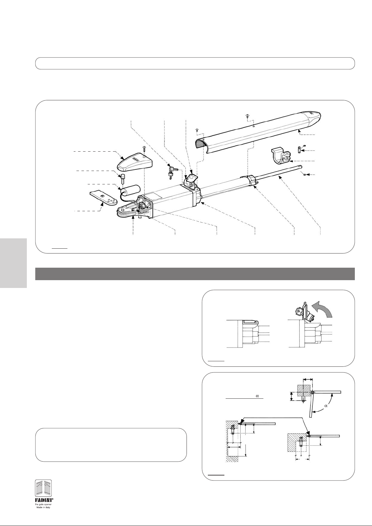
FITTING NUPI 66
PIC. 1
This explains how to remove the operator cover and fix the
actuator. The first operation is to unlock the operator: push the
lock flap to one side, insert the key and turn it 90° clockwise. The
locking barrel can be tilted open and the operator is now released
(pic. 2). Unscrew the two screws that fix the operator cover and
remove it. Unscrew the screw that fixes the rear end cover and
remove it. The actuator is so ready for fixing operations.
RELEASE
DEVICE
RELEASE
FLAP COVER
FASTENER
COVER WITH
CAP
FIXING PIN
FRONT
FIXING
BENZING
RING
TERMINALSCABLE
RELEASE VALVE
BLOCK
CLOSED
CYLINDER
HEAD
UNLOCKED GATELOCKED GATE
PISTON
SHAFT
OPEN
• Special fitting
There can be cases where special fitting requirements are needed
to meet (gate hinges on the post edge line, brickwork to be
indented, special opening,...). NUPI 66 is supplied complete with
an adjustable rear fixing pIate: a pattern of fixing holes makes
the rear fixing extremely versatile to suit any gate. Refer to the
diagram on the right for fixing geometry (pic. 3).
ELECTRIC LOCK
An electric lock is recommended in installations where
each gate leaf exceeds 1.8 meters and is subjected to high
winds or are close boarded gates.
10
PIC. 2
GATE POST 150x150mm
AB
130 130 95°
130 120 100°
70 130
PIC. 3
RELEASING SYSTEM. DETAILS.
GATE MOVEMENT CENTRES
CLOSED
130
GATE
1˙210
200
A
B
CLOSED GATE
130
70 130
200
Page 3
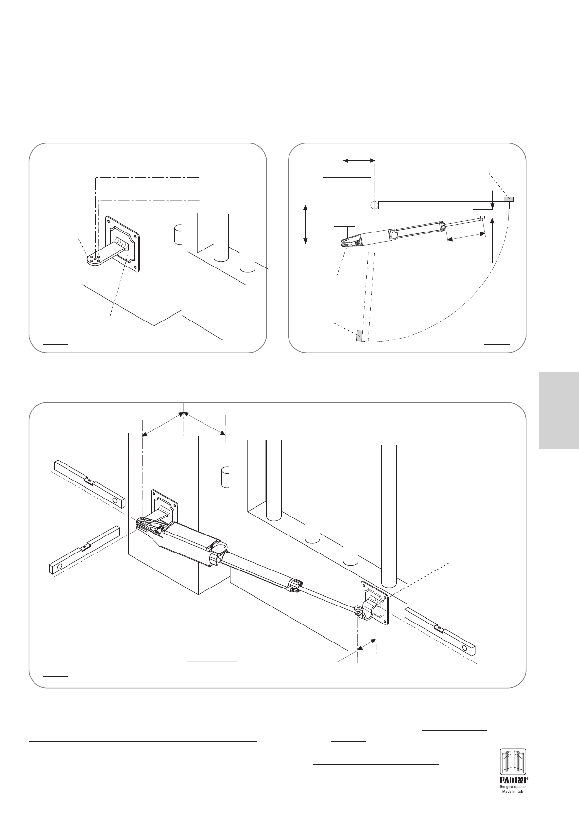
IMPORTANT: It is important to temporarily fix the operator rear casting using the center hole in the fixing plate and, once the installation
is completed, move the rear fixing to the inner hole.
IMPORTANT: it is necessary to firmly fix the gate stops to the ground in the open and closed gate positions (See pic. 5 on page 11 and
pic. 7 on page 12, parts 5 and 15) before installing the operator.
- A reinforcement plate (pic. 6) is recommended for the rear fixing, either to be embedded in the gate post, anchoring plates to be welded
to improve holding, or bolted to it so that the operator rear fixing can be welded to it in full respect of the geometry indicated below. See
distances A and B in pic.5 (distances are strictly referred to the center lines of the gate hinge and operator rear fixing)
Pierced
fixing plate
Reinforcement plate
Temporary installation axis to coincide
with center hole
Final installation axis to coincide with
inner hole
=130
B
Rear casting
Ground stop in
open gate
position
A=130
Closed gate
Ground stop in
closed gate position
260
=80
D
95°
PIC. 4 PIC. 5
- By means of a spirit level, make sure that the fixing plates are perfectly levelled, respect distance D for the front fixing, the gate in closed
position, ie. operator shaft driven 260 mm out.
A=130B=130
English
Spirit level
Never weld the front fixing
Spirit level
This distance to allow
1cm clearance between the cover
and the gate in open position
D=80
bracket directly to the gate. Use
a reinforcement plate. Remove
the operator before welding
Spirit level
PIC. 6
- At this stage NUPI 66 is fixed to the gate leaf. Note that it is locking when the release lid is closed; with the lid in the open
position the locking device is overridden and the gate can be pushed open by hand (pic.2 on page 10). The electrical connections
of the power supply cable to the terminal board are the next step. Remove the cable fastener. Connect
central terminal and the two live wires to the lateral terminals (pic. 9 on page 12) in parallel with the capacitor. Put back the
cable fastener.
On connecting the electronic control panel Elpro 7 RP, it is advised to set the
torque control switch to position 3
(pic. 10 on page 13 and pic. 11 on page 14).
the neutral to the
11
Page 4

ELECTRICAL WIRING DIAGRAM
The diagram here below shows the electrical connections of all the accessories that are available for the system:
13
1
9
English
10
12
11
n°2x1
n°2x1
5
.
n°3x1
n°4x1.5
14
2
IMPORTANT: All the system must be properly earthed
1 - PHOTOCELL RECEIVER TRIFO 11
2 - JUNCTION BOX
3 - POST WITH PHOTOCELL PROJECTOR TRIFO 11
4 - OIL-HYDRAULIC ACTUATORS NUPI 66
5 - CLOSED GATE STOP REQUIRED
6 - RADIO TRANSMITTER ASTRO 43/2 TR SMALL
7 - POST WITH PHOTOCELL RECEIVER TRIFO 11
8 - PHOTOCELL PROJECTOR TRIFO 11
8
cable RG58
n°4x1
n°4x1
4
5
4
n°4x1.5
15
n°2x1
3
15
n°4x1
6
7
9 - KEYSWITCH CHIS 37 SURFACE MOUNT
10 - FLASHING LAMP MIRI 4
11 - PLUG-IN RADIO RECEIVER CARD ASTRO 43/2 R
12 - ELECTRONIC CONTROL PANEL ELPRO 7 RP
13 - AERIAL BIRIO A8
14 - 0.03A MAGNETIC-THERMAL CIRCUIT BREAKER
(BEYOND 100m 2.5mm
2
Ø CABLE TO BE USED )
15 - OPEN GATE STOP REQUIRED
PIC. 7
PIC. 8 PIC. 9
LIVE 1
NEUTRAL - BLUE
LIVE 2
NOTE: BY EXCHANGING THE POSITION OF L1 WITH L2 THE ELECTRIC
MOTOR ROTATION IS REVERSED.
TERMINALS FITTED ON TO
THE OPERATOR BRACKET BLOCK
12.5 μF CAPACITOR
SUPPLY CABLE
230V - 50 Hz
– FLEXIBLE
– FLAME-PROOF NPI
– 450/750 - 4x1.5 mm
– CEI STANDARD 20-52
THE NEUTRAL BLUE WIRE
TO BE CONNECTED TO THE
CENTRAL TERMINAL
THE TWO LIVE WIRES TO
BE CONNECTED TO THE
LATERAL TERMINALS
PARALLEL TO THE
CAPACITOR
2
IT IS IMPORTANT TO AVOID
ANY SHARP BENDS WITH
THE CABLE. IT MUST
DANGLE IN A WIDE LOOP
12
Page 5

WIRING DIAGRAM CONTROL PANEL ELPRO 7 RP
IMPORTANT: Elpro 7 RP is specifically designed to suit NUPI 66 only. The manufacturer declines any responsibility for damages caused by
incorrect use, or applications with accessories that are not FADINI.
2
For the electrical connections to the motor of NUPI 66 and mains use 1.5 mm
For the photo cells, keyswitches, flashing lamp, and other accessories you can use 1 mm
Make sure that all the electrical connections are done in compliance with this diagram.
Once the terminals 19 - 20 are supplied with 230V - 50Hz power, the neutral and live properly connected, the red led No. 1 (L1) illuminates
to confirm that the board has voltage.
Read the instructions contained in the ELPRO 7 RP box.
cables.
2
wires.
GB
L7
Elpro 7 RP
L1
L2
1
2
3
COMMON
PHOTOCELLS NC
RP
7
PLUG-IN RADIO
CARD SUPPORT
PROGRAMMING “P”
BUTTON
L3
L4
74
RADIO
CLOSE
STOP NC
OPEN
L5
24V max 3W
ELECTRONIC CONTROL PANEL FOR NUPI 66
WITH PROGRAMMABLE RADIO TECHNOLOGY
DIP-SWITCH
6
4
2
1
3
L6
85
96
INDICATOR
1 No. Radio receiver
2 Pairs photocells
7
5
10
24V OUTPUT max load:
- LEARNING TIMES BY REMOTE CONTROL
- AUTOMATIC/SEMI-AUTOMATIC OPERATING MODES
- STEP BY STEP MODE INTERMIDIATE STOP
- PARTIAL PEDESTRIAN OPENING
- DIP-SWITCH SETTING
ON
OFF
8
COURTESY LIGHT
OR 12V AC RELAY FOR
ELECTRIC LOCK
SINGLE-PHASE
electric lock if
12345
ELECTRONIC TORQUE
11
12
COMMON
M1
MOTOR M1
(actuator and
required)
TRANSFORMER
CONTROL
13
1514
COMMON
M2
SINGLE-
PHASE
MOTOR M2
2A 24V low
voltage fuse
19
20
181617
NEUTRAL
PHASE
POWER SUPPLY
230V 50Hz SINGLE-PHASE
25W max
FLASHING LAMP 230V
5 A line
fuse
5 A line
fuse
English
PIC. 10
Drwg. No.
4153
Elpro 7 RP is an electronic control panel developed for Nupi 66. The main feature of this unit is the capability to learn the required working
times during operation (gate delay in open and close cycles, dwell time). It is recommended to carry out the installation in strict compliance
with the rules of good technique and fit the system with ground stops in the Open and Closed positions.
Elpro 7RP is to be powered with 230 V single-phase voltage. It is manufactured in conformity to 2006/95 CE Low Voltage Safety Norms
and 2004/108/CE and 92/31 CEE Norms for the Electro Magnetic Compatibility. Installation is to be carried out by qualified technicians in
compliance with the existing safety regulations. The manufacturer is not liable for incorrect use of the equipment and reserves the right
to do changes to the unit and this manual any time.
13
Page 6

GB
7
RP
ELECTRONIC CONTROL PANEL FOR NUPI 66
WITH PROGRAMMABLE RADIO TECHNOLOGY
DESCRIPTION OF FUNCTIONS OF THE CONTROL PANEL FOR SWINGING GATES
ELECTRICAL CONNECTIONS:
- The control panel must be installed in a sheltered, dry place, inside the box provided with it.
- Fit the mains to the control panel with a 0.03A high performance circuit breaker.
- Use 1.5mm2 section wires for voltage supply and electric motor. Maximum recommended distance 50m.
- Use 1mm
- Bridge terminals 1 and 2 if no photocells are required.
- Bridge terminals 3 and 6 if no key- or push-button switches are required.
N.W.: To fit extra accessories such as lights, CCTV etc. use only solid state relays to prevent damages to the microprocessor
LOGIC: Elpro 7 RP is supplied with pre-set working times to allow the first installation:
- Working time is about 20 s
- Gate Delay Times: - Opening=2 s
- Closing=6 s
- Dwell on automatic Mode=15 s
Once satisfied that the system is working all right, new working times can be programmed to meet the user's needs or the installation requirements.
Elpro 7RP functions can be set by Dip-switches, both before and after the times have been stored by the unit.
LEARNING THE TIMES: ELPRO 7 RP learning operation is quite easy and can be achieved either by the P button on the PCB or by the remote
control after entering setting mode, see point 1).
Starting the unit to learn the required times: with the gate in closed position pulse the equipment to one complete cycle, ie. open-dwell-close.
Important:
1) In order to avoid setting times which are not suitable to the correct gate functioning, some time limits are pre-set. Beyond these values the
M1 and M2 Motor Run time: max.55s Dwell time on Automatic Mode: maximum 90s
2) During the learning operation, no other functions can be activated, the Photocells and the Stop button are out of service
3) If the new setting operation is interrupted (for example: mains cut off), the times in the previous setting are memorized.
4) Normally, not on programming mode, the P button has the same function as a remote control button and it is possible to test the system by
2
section wires for limit switches, photocells, push-buttons/key-switch and accessories.
automation will start with the maximum pre-set time:
pulsing it; the Led 7 becomes a simple indicator, the same as the indicator to terminal 8.
English
Led Status Indication:
L1=230V 50Hz power supply. Alight
L2=Photocells, if obstructed light goes off
L3=Open. Alight whenever an Open pulse is given
L4=Close. Alight whenever a Close pulse is given
L5=Stop. It goes off on pulsing Stop
L6=Radio. It goes on by pressing a transmitter button
L7=Gate Status; and programming led
24V 3W Indicator:
8
3
COMMON
IMPORTANT: The Elpro 7 RP control panel is supplied with open/close time memory.
Led On = the Gate is Open
Led Off = the Gate is Closed
Fast Flash = closing movement
Slow Flash = opening movement
Pedestrian Opening (M1 Motor by Open pulse):
Partial opening for pedestrians is only allowed in
closed gate position by pulsing to Open (the gate
closes after the dwell time if set to Automatic
Dip-Switch 3=ON)
-the first pulse operates 1 gate leaf (M1)
-the second pulse operates the second gate leaf
Dip-Switch:
1= ON Photocells, Stop during opening
2= ON Radio no reversing during Opening
3= ON Automatic Closing
4= ON Pre-flashing in service
5= ON Radio step by step. Stop in between
6= ON No delay on opening
7= ON Additional pushing on the gate leaf after closing
8= ON Pedestrian opening by Open button
MORE POWER
DIP-SWITCH
1 45 6782
3
ON: 1 gate leaf for
OFF: Standard
8
operation
ON
OFF
pedestrian opening
+
TORQUE CONTROL SETTING: Adjust torque from lower level (step 1) up
to the required amount of power step by step to achieve a correct
performance of the system so that the gates are operated as required
and any injuring hazard is prevented.
Please note, torque is to be adjusted by a technician.
TORQUE ADJUSTING WHEN LIGHT GATES ARE INVOLVED: (made of timbers, PVC or aluminium etc. ...) replace the existing capacitor with a
8 μF one and adjust torque accordingly starting from step one (lowest setting).
ELECTRONIC
TORQUE
CONTROL
_
12 45
LESS POWER
PIC. 11
14
Page 7

GB
7
RP
ELECTRONIC CONTROL PANEL FOR NUPI 66
WITH PROGRAMMABLE RADIO TECHNOLOGY
DESCRIPTION OF FUNCTIONS OF THE CONTROL PANEL FOR SWINGING GATES
Preliminary notes to Learning Mode:
- Make sure that the gate is closed
- Make sure that the gate stops in the respective open and closed gate positions
are firmly fixed to the ground
1°
1°
st
1
Operation:
Cut off power supply to Elpro 7 RP by removing the 2A 24V Low
Voltage white Fuse, which is on the right upper side of the PCB
2°
2°
2nd
Operation:
Hold the button “P” pressed and re-power the PCB by inserting
the 24V Low Voltage Fuse back into its holder.
3°
3rd
Operation:
When the Led L7 illuminates, release button “P”: Led L7 will flash
5 times and the flashing lamp will illuminate: the program “learning
working times” has been entered.
IMPORTANT: at this stage two options are allowed to go on with setting
ie. learning the required operating times: by the “P” button or by remote
!
control. The last option allows the installation agent to have direct visual
control of the
by the gates.
operation being performed
L7
L7
L7
L7
7°
Birio
7th
Operation:
A pulse stops M2 motor
(second gate wide open on open gate stop)
The time passing from 7th to 8th operation is stored by the system as
“Dwell Time”, in service on AUTOMATIC MODE (Dip No.3=ON) or out of
!
service (Dip No.3=OFF, dwell time still in the system memory but not applicable).
M2
8°
M2
th
Operation:
8
A Pulse to close starts M2 motor
(M2 gate starts closing)
The time between the 8
!
as “Gate Delay Time on Closing Cycle”
Birio
th
and 9th operations is stored by the system
9°
M2
9th
Operation:
A pulse to close starts M1 motor
(M1 gate starts closing)
Birio
M1
M1
M1
English
Birio
4°
Birio
4th
Operation:
A pulse to open starts M1 motor
(the first gate starts opening)
The time passing from 4th to 5th operations is stored by the system as the
Gate Delay Time in Open Cycle, with the options in service (Dip No.6 =ON)
!
or out of service (Dip No. 6=OFF, the time is stored but no delay will occur).
M2
5°
M2
Birio
5th
Operation:
A pulse to open starts M2 motor
(second gate starts opening)
6°
6th
Operation:
A pulse stops M1 motor
(first gate wide open on open gate stop)
Birio
M2
M1
M1
M1
10°
M1
M2
Birio
10th
Operation:
A pulse stops M2 motor (M2 gate on closed gate position)
In order to ensure that the gate is securely held in stop position, it is advised
to pulse the actuator ie. gate to stop approx. 3-4 seconds after the gate has
reached the end of the permitted stroke on the closed gate stop position.
11°
M1
M2
Birio
11th
Operation:
A pulse stops M1 motor (M1 gate on closed gate position)
In order to ensure that the gate is securely held in stop position, it is advised
to pulse the actuator ie. gate to stop approx. 3-4 seconds after the gate has
reached the end of the permitted stroke on the closed gate stop position.
The 11th operation concludes the procedure for the control panel to learn the
required working times.
After the learning procedure, it is possible to set the operating modes either
ON/OFF as required by means the Dip-switches on the PCB.
Drwg. No.
4153
15
Page 8

NUPI 66 TECHNICAL SPECIFICATIONS
OIL-HYDRAULIC ACTUATOR
Pump flow rate - P5 ..............................................................1.4
/min.
Working pressure......................................................2 MPa (20 Bars)
Working temperature....................................................–20°C +80°C
Shaft travelling time.................................................................21 sec.
Power oil................................................................................Oil Fadini
Piston stroke ............................................................................280 mm
Piston diametre..........................................................................45 mm
Shaft diametre ............................................................................16 mm
Pushing power open................................................................2˙720 N
Pulling power close..................................................................3˙120 N
Weight of NUPI 66 complete........................................................8 Kg
Protection standards..................................................................IP 553
Overall dimensions (LxWxH)...................................1˙240x86x86 mm
ELECTRIC MOTOR
Power output...........................................................0.18 KW (0.25 HP)
Supply voltage ..............................................................................230 V
Frequency......................................................................................50 Hz
Absorbed current..........................................................................1.2 A
Absorbed power ........................................................................250 W
Capacitor.....................................................................................12.5 μF
Motor rotation speed..........................................................1˙350 rpm
Intermittent service .........................................................................S 3
Flexible electric cable..............................CEI 20-52 FROR 450-750 V
Class......................................................................................................H
Gate height and width (mm) ..................................H 1˙200, W 1˙600
Max. weight per gate leaf up to 2m ........................................150 Kg
60
86
70
160 230 47 803
1˙240
86
48
1˙240
83
l'apricancello
FADINI
PIC. 12
SERVICE
Duty cycle ...19 sec. Opening - 30 sec. Stop - 21 sec. Closing - 30 sec. Stop
Time of one complete cycle........................................................100 s
No. of complete cycles Opening - Stop - Closing - Stop.........36/h
No. of cycles a year, 8 hours’ service a day........................105˙000
WARNINGS
- Before installing the equipment carry out a Risk Analysis and fit any required device in compliance with EN 12445 and EN 12453 Safety Norms.
- It is recommended to keep to the instructions here outlined - check the specifications on the motor sticker with your mains supply.
- Dispose properly of the packaging: cardboard, nylon, polystyrene, through specialized companies.
- Should the operator be removed, do not cut the electric cables. These must be properly removed from the terminal board in the junction box.
- Switch off the mains switch before removing the junction box cover where the electric cables are terminated.
- All the system must be earthed by using the yellow/green wire.
English
- It is recommended to read the regulations, suggestions and remarks quoted in the booklet “Safety Norms”.
CHECKS AND MAINTENANCE:
To achieve an optimum performance and longer life of the equipment and in observance of the safety regulations, it is recommended that inspections and proper
maintenance are made by qualified technicians to the whole installation ie. both the mechanical and electronic parts, as well as wiring.
- Mechanical parts: maintenance every 6 months approx.
- Electronic apparatus and safety equipment: maintenance inspection monthly.
- Ordinary and extraordinary maintenance to be agreed between buyer and installation agent.
The growth of MECCANICA FADINI has always been based on the development of guaranteed products thanks to our “TOTAL QUALITY CONTROL” system
which ensures constant quality standards, updated knowledge of the European Standards and compliance with their requirements, in view of an ever
increasing process of improvement.
2003/108/CE Directive
for waste electrical and
GB
electronic equipments
DISPOSE OF PROPERLY
ENVIRONMENT-NOXIOUS MATERIALS
¤
s.n.c.
AUTOMATIC GATE MANUFACTURERS
Via Mantova, 177/A - C.P.126 - 37053 Cerea (Verona) Italy
Tel. +39 0442 330422 r.a. - Fax +39 0442 331054
e-mail: info@fadini.net - www.fadini.net
16
The manufacturer reserves the right to make amendments to this manual without prior
notice and declines all responsibility for any errors, personal injury or damage to property.
 Loading...